US7658091B2 - Method for the audible output of a piece of information in an analysis system - Google Patents
Method for the audible output of a piece of information in an analysis system Download PDFInfo
- Publication number
- US7658091B2 US7658091B2 US11/565,149 US56514906A US7658091B2 US 7658091 B2 US7658091 B2 US 7658091B2 US 56514906 A US56514906 A US 56514906A US 7658091 B2 US7658091 B2 US 7658091B2
- Authority
- US
- United States
- Prior art keywords
- audible
- signal generator
- analysis system
- controlling
- test
- Prior art date
- Legal status (The legal status is an assumption and is not a legal conclusion. Google has not performed a legal analysis and makes no representation as to the accuracy of the status listed.)
- Active, expires
Links
Images

Classifications
-
- A—HUMAN NECESSITIES
- A61—MEDICAL OR VETERINARY SCIENCE; HYGIENE
- A61B—DIAGNOSIS; SURGERY; IDENTIFICATION
- A61B5/00—Measuring for diagnostic purposes; Identification of persons
- A61B5/145—Measuring characteristics of blood in vivo, e.g. gas concentration, pH value; Measuring characteristics of body fluids or tissues, e.g. interstitial fluid, cerebral tissue
- A61B5/14532—Measuring characteristics of blood in vivo, e.g. gas concentration, pH value; Measuring characteristics of body fluids or tissues, e.g. interstitial fluid, cerebral tissue for measuring glucose, e.g. by tissue impedance measurement
-
- A—HUMAN NECESSITIES
- A61—MEDICAL OR VETERINARY SCIENCE; HYGIENE
- A61B—DIAGNOSIS; SURGERY; IDENTIFICATION
- A61B5/00—Measuring for diagnostic purposes; Identification of persons
- A61B5/74—Details of notification to user or communication with user or patient ; user input means
- A61B5/7405—Details of notification to user or communication with user or patient ; user input means using sound
- A61B5/7415—Sound rendering of measured values, e.g. by pitch or volume variation
-
- G—PHYSICS
- G01—MEASURING; TESTING
- G01N—INVESTIGATING OR ANALYSING MATERIALS BY DETERMINING THEIR CHEMICAL OR PHYSICAL PROPERTIES
- G01N33/00—Investigating or analysing materials by specific methods not covered by groups G01N1/00 - G01N31/00
- G01N33/48—Biological material, e.g. blood, urine; Haemocytometers
- G01N33/483—Physical analysis of biological material
- G01N33/487—Physical analysis of biological material of liquid biological material
- G01N33/48785—Electrical and electronic details of measuring devices for physical analysis of liquid biological material not specific to a particular test method, e.g. user interface or power supply
-
- G—PHYSICS
- G01—MEASURING; TESTING
- G01N—INVESTIGATING OR ANALYSING MATERIALS BY DETERMINING THEIR CHEMICAL OR PHYSICAL PROPERTIES
- G01N35/00—Automatic analysis not limited to methods or materials provided for in any single one of groups G01N1/00 - G01N33/00; Handling materials therefor
- G01N35/00584—Control arrangements for automatic analysers
- G01N35/00722—Communications; Identification
- G01N2035/00891—Displaying information to the operator
- G01N2035/009—Displaying information to the operator alarms, e.g. audible
Definitions
- the invention relates to a method for the audible output of a piece of information by an audible signal generator, where the signal generator is arranged in an analysis system for analysing a sample using a test element, and relates to an analysis system having an audible signal generator.
- test elements for example body fluids such as blood or urine
- analysis systems are frequently used in which the samples to be analysed are placed on a test element and possibly react with one or more reagents in a test array on the test element before they are analysed.
- Optical, particularly photometric, and electrochemical evaluation of test elements are the most common methods for quickly determining the concentration of analytes in samples.
- Photometric and electrochemical evaluations are generally used in the field of chemical analysis, environmental analysis and in particular in the field of medical diagnosis.
- test elements which are evaluated photometrically or electrochemically carry a great weight.
- test elements there are various forms of test elements.
- essentially square lamellae, also called slides, are known, in the centre of which there is a multilayer test array. Diagnostic test elements in strip form are called test strips.
- capillary test elements are known from the prior art, e.g. from WO 99/29429.
- Sample analysis performed using a test element in an analysis system produces an analysis result, e.g. an ascertained blood sugar concentration value.
- This analysis result is usually indicated on a visual display panel in the analysis system, e.g. on a liquid crystal display.
- an audible output is additionally provided for users who suffer from visual impairment or blindness.
- WO 03/039362 A1 relates to a reagentless whole-blood glucose meter in which a processor communicates measured concentration results and/or other information to a controller.
- the controller operates a visual display panel for presenting the information to a user.
- an audible output for the information may be provided.
- WO 02/062212 A1 relates to a management system for personal health which comprises an output apparatus which communicates a treatment recommendation to a patient.
- the output apparatus can transmit the treatment recommendation using audible, visible or tactile means, for example using a warning tone generator or a system indicator.
- a piece of information is audibly output usually using an audible signal generator or a loudspeaker.
- U.S. Pat. No. 4,014,016 relates to an output system for blind people in which information is transmitted by audible signals.
- This is an output system in a pocket calculator, for example, in which the digits of a calculation result are output using uniformly spaced tone sequences with a different number of tones at the same frequency.
- DE 25 50 614 relates to a method for audible output through the production of an encoded electrical output signal which denotes a recoverable piece of information.
- This encoded electrical output signal is used to produce a predetermined number of audible tones at essentially the same frequency, the number of these tones denoting the recoverable piece of information.
- the recoverable piece of information may be at least one decimal number, for example, with the number of audible tones being equal to the decimal number.
- Audible output in an analysis system for analysing a sample using a test element needs to meet particular demands on the operability thereof.
- the health or even the life of the user may depend on the result of the analysis being output correctly in audible form.
- a measured blood glucose value governs the insulin dose which is administered to a diabetic.
- the invention achieves this by a method for the audible output of a piece of information by an audible signal generator, where the signal generator is arranged in an analysis system and the analysis system analyses a fluid sample using a test element, where analysis results are generated and are processed by a data processing unit, and where a control unit in the analysis system actuates the signal generator, so that the signal generator audibly outputs a piece of information, the signal generator sending an audible test signal in order to test the operability of the signal generator.
- the invention also relates to an analysis system for analysing a fluid sample using a test element, containing an audible signal generator for audibly outputting a piece of information, an analysing for generating analysis results, a data processing unit for processing the analysis results and a control unit, the control unit being designed such that it actuates the signal generator to send an audible test signal in order to test the operability of the signal generator.
- the invention also relates to the use of an audible signal generator, which, for the purpose of audibly outputting a piece of information, is arranged in an analysis system for analysing a sample using a test element, for checking the operability of the signal generator by sending an audible test signal.
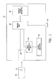
- FIG. 1 is a block diagram representation of an analysis system for analyzing a fluid sample.
- an analysis system 10 is a system for analysing a fluid sample 12 , for example for analysing blood, urine or interstitial fluid, particularly a blood sugar meter.
- the data processing unit 16 in the analysis system 10 receives the analysis results generated in the analysis of a fluid sample 12 arranged on the test element 14 and processes them. By way of example, it takes the analysis results measured (e.g. photometrically or electrochemically) and calculates the concentration of an analyte in the fluid sample 12 .
- the control unit 18 contained in the analysis system 10 actuates the signal generator 20 , inter alia, for example when the signal generator 20 is intended to be used to output the information about which analysis result processed by the data processing unit 16 has been obtained from the analysis of a fluid sample 12 .
- the audible signal generator 20 provided in the analysis system 10 may be any audible signal generator with which a person skilled in the art is familiar, e.g. a buzzer, a loudspeaker or a piezoelectric signal generator.
- the information which is output may be a piece of information relating to the operating status of the analysis system 10 or to an analysis result, for example.
- the signal generator 20 in the analysis system 10 sends an audible test signal in order to test the operability of the signal generator 20 .
- the user of the analysis system 10 is then able to identify whether or not the audible test signal is correct. If the audible test signal is not sent correctly by the signal generator 20 , it can be assumed that a piece of information which has been output by the audible signal generator 20 might likewise be incorrect.
- the illustrated analysis system 10 contains a switch 22 which is tripped by a test element's being pushed or inserted into the analysis system 10 , the switch 22 being coupled to the controller 18 such that the controller 18 actuates the signal generator 20 to send an audible test signal when the switch 22 is tripped.
- a test element 14 needs to be pushed or inserted into the analysis system 10 manually or automatically before a fluid sample 12 is analysed, into a sample holding position for holding the fluid sample 12 on the test element 14 and/or a measuring position for performing a measurement and generating analysis results.
- the audible test signal may also be sent as soon as the user of the analysis system 10 pushes a particular button 24 on the analysis system 10 (e.g. the button for turning on the analysis system) or automatically at at least one particular instant during operation of the analysis system 10 .
- the signal generator 20 sends an audible test signal which comprises a tone or a sequence of tones, the tone or the sequence of tones essentially having a constant frequency or the tone or the sequence of tones having a changing frequency.
- the sequence of tones may be sent such that the individual tones merge into one another or are at least to some extent interrupted by pauses between the tones.
- the signal generator 20 may send an audible test signal which comprises a sequence of tones, at least some of the tones having different tone lengths or the tones having essentially the same tone length.
- the audible signal generator 20 may also send an audible test signal which comprises a tone or a sequence of tones, the volume of the tone or of the sequence of tones changing or the tone or the sequence of tones having essentially the same volume.
- the audible test signal should have as many of the features as possible which an audible signal sent by the signal generator 20 during normal operation of the analysis system 10 for the purpose of outputting a piece of information can have. If an audible signal of this kind for outputting a piece of information comprises merely a sequence of tones having essentially the same frequency, tone length and volume, with the individual tones being interrupted by pauses, then the test signal should have at least the same features to be able to detect a malfunction reliably. In addition, the test signal should be designed as far as possible such that a user can easily identify the correct test signal and any deviations therefrom.
- the signal generator 20 sends the test signal at the start of the analysis system's being started up.
- the signal generator 20 can send the or at least one additional test signal at any other instant during operation of the analysis system 10 .
- the user can refrain from performing an analysis if he detects a malfunction in the audible signal generator 20 in the analysis system 10 right at the start. This means that it is possible to avoid, by way of example, taking useless painful blood samples or wasting test elements 14 for analyses using the analysis system 10 which are not able to be used on account of the malfunction in the audible signal generator 20 .
- the user upon identifying an incorrect test signal, the user can ask a supervisor whose vision is not impaired to read off the information from a visual indicator if a visual indicator of this kind is available.
- the sending of the test signal right at the start of the analysis system's being started up can be triggered by the analysis system's being turned on or by a test element's being pushed into the analysis system 10 automatically or by the user, for example.
- the operability of the signal generator 20 can be checked using the audible test signal at the same time as the operability of a visual indicator 26 in the analysis system 10 , e.g. a liquid crystal display, is checked, which means that there is no need to accept any additional delay until the analysis system 10 is ready for use.
- the audible signal generator 20 audibly encodes a piece of information which can be represented as a number with at least one digit.
- the number may be a concentration (ascertained using the analysis system) for an analyte in a sample 12 analysed on a test element 14 , particularly the glucose concentration in blood.
- the number may comprise one or more digits and may possibly have places after a decimal point.
- the piece of information encoded by the audible signal generator 20 may comprise a piece of information regarding the operational readiness of the analysis system 10 (e.g. the fact that the analysis system has been turned on) or a piece of information about the instant for a particular action to be performed by the user (e.g. the instant for applying his finger to a piercing aid integrated in the analysis system 10 or the instant for transferring a sample 12 for analysis to a test element 14 ).
- the signal generator 20 may also audibly output a piece of information regarding the need to replace or refill a consumable used in the analysis system 10 (e.g. test element, test element magazine, battery, lancet or disposable).
- the audible signal generator 20 audibly encodes a piece of information as a sequence of tones, the number of tones denoting the piece of information.
- a number can be audibly output such that a number of audible output tones respectively corresponds to a digit value for each digit in the number, with the output of a respective new digit being indicated by a longer pause or another audible signal, for example.
- a particular audible signal may be provided for a decimal point and/or an arithmetic sign.
- the invention also relates to the use of an audible signal generator, which, for the purpose of audibly outputting a piece of information, is arranged in an analysis system for analysing a sample using a test element, for checking the operability of the signal generator by sending an audible test signal.
Abstract
Description
Claims (18)
Applications Claiming Priority (3)
| Application Number | Priority Date | Filing Date | Title |
|---|---|---|---|
| EP05026525A EP1793228A1 (en) | 2005-12-05 | 2005-12-05 | Method to give acoustically an information in an analytical system |
| EP05026525 | 2005-12-05 | ||
| EPEP05026525.5 | 2005-12-05 |
Publications (2)
| Publication Number | Publication Date |
|---|---|
| US20070144235A1 US20070144235A1 (en) | 2007-06-28 |
| US7658091B2 true US7658091B2 (en) | 2010-02-09 |
Family
ID=35976415
Family Applications (1)
| Application Number | Title | Priority Date | Filing Date |
|---|---|---|---|
| US11/565,149 Active 2027-09-01 US7658091B2 (en) | 2005-12-05 | 2006-11-30 | Method for the audible output of a piece of information in an analysis system |
Country Status (7)
| Country | Link |
|---|---|
| US (1) | US7658091B2 (en) |
| EP (1) | EP1793228A1 (en) |
| JP (1) | JP2007155732A (en) |
| CN (1) | CN1979173A (en) |
| AT (1) | ATE480772T1 (en) |
| CA (1) | CA2566966C (en) |
| DE (1) | DE502006007824D1 (en) |
Families Citing this family (55)
| Publication number | Priority date | Publication date | Assignee | Title |
|---|---|---|---|---|
| US6391005B1 (en) | 1998-03-30 | 2002-05-21 | Agilent Technologies, Inc. | Apparatus and method for penetration with shaft having a sensor for sensing penetration depth |
| US8641644B2 (en) | 2000-11-21 | 2014-02-04 | Sanofi-Aventis Deutschland Gmbh | Blood testing apparatus having a rotatable cartridge with multiple lancing elements and testing means |
| US7025774B2 (en) | 2001-06-12 | 2006-04-11 | Pelikan Technologies, Inc. | Tissue penetration device |
| US9226699B2 (en) | 2002-04-19 | 2016-01-05 | Sanofi-Aventis Deutschland Gmbh | Body fluid sampling module with a continuous compression tissue interface surface |
| DE60238119D1 (en) | 2001-06-12 | 2010-12-09 | Pelikan Technologies Inc | ELECTRIC ACTUATOR ELEMENT FOR A LANZETTE |
| US8337419B2 (en) | 2002-04-19 | 2012-12-25 | Sanofi-Aventis Deutschland Gmbh | Tissue penetration device |
| US7316700B2 (en) | 2001-06-12 | 2008-01-08 | Pelikan Technologies, Inc. | Self optimizing lancing device with adaptation means to temporal variations in cutaneous properties |
| US9427532B2 (en) | 2001-06-12 | 2016-08-30 | Sanofi-Aventis Deutschland Gmbh | Tissue penetration device |
| US9795747B2 (en) | 2010-06-02 | 2017-10-24 | Sanofi-Aventis Deutschland Gmbh | Methods and apparatus for lancet actuation |
| US7981056B2 (en) | 2002-04-19 | 2011-07-19 | Pelikan Technologies, Inc. | Methods and apparatus for lancet actuation |
| US7749174B2 (en) | 2001-06-12 | 2010-07-06 | Pelikan Technologies, Inc. | Method and apparatus for lancet launching device intergrated onto a blood-sampling cartridge |
| US7331931B2 (en) | 2002-04-19 | 2008-02-19 | Pelikan Technologies, Inc. | Method and apparatus for penetrating tissue |
| US7674232B2 (en) | 2002-04-19 | 2010-03-09 | Pelikan Technologies, Inc. | Method and apparatus for penetrating tissue |
| US8579831B2 (en) | 2002-04-19 | 2013-11-12 | Sanofi-Aventis Deutschland Gmbh | Method and apparatus for penetrating tissue |
| US8360992B2 (en) | 2002-04-19 | 2013-01-29 | Sanofi-Aventis Deutschland Gmbh | Method and apparatus for penetrating tissue |
| US7976476B2 (en) | 2002-04-19 | 2011-07-12 | Pelikan Technologies, Inc. | Device and method for variable speed lancet |
| US9795334B2 (en) | 2002-04-19 | 2017-10-24 | Sanofi-Aventis Deutschland Gmbh | Method and apparatus for penetrating tissue |
| US8784335B2 (en) | 2002-04-19 | 2014-07-22 | Sanofi-Aventis Deutschland Gmbh | Body fluid sampling device with a capacitive sensor |
| US9248267B2 (en) | 2002-04-19 | 2016-02-02 | Sanofi-Aventis Deustchland Gmbh | Tissue penetration device |
| US7909778B2 (en) | 2002-04-19 | 2011-03-22 | Pelikan Technologies, Inc. | Method and apparatus for penetrating tissue |
| US7491178B2 (en) | 2002-04-19 | 2009-02-17 | Pelikan Technologies, Inc. | Method and apparatus for penetrating tissue |
| US9314194B2 (en) | 2002-04-19 | 2016-04-19 | Sanofi-Aventis Deutschland Gmbh | Tissue penetration device |
| US7175642B2 (en) | 2002-04-19 | 2007-02-13 | Pelikan Technologies, Inc. | Methods and apparatus for lancet actuation |
| US7713214B2 (en) | 2002-04-19 | 2010-05-11 | Pelikan Technologies, Inc. | Method and apparatus for a multi-use body fluid sampling device with optical analyte sensing |
| US8372016B2 (en) | 2002-04-19 | 2013-02-12 | Sanofi-Aventis Deutschland Gmbh | Method and apparatus for body fluid sampling and analyte sensing |
| US7297122B2 (en) | 2002-04-19 | 2007-11-20 | Pelikan Technologies, Inc. | Method and apparatus for penetrating tissue |
| US7229458B2 (en) | 2002-04-19 | 2007-06-12 | Pelikan Technologies, Inc. | Method and apparatus for penetrating tissue |
| US8221334B2 (en) | 2002-04-19 | 2012-07-17 | Sanofi-Aventis Deutschland Gmbh | Method and apparatus for penetrating tissue |
| US7892183B2 (en) | 2002-04-19 | 2011-02-22 | Pelikan Technologies, Inc. | Method and apparatus for body fluid sampling and analyte sensing |
| US7901362B2 (en) | 2002-04-19 | 2011-03-08 | Pelikan Technologies, Inc. | Method and apparatus for penetrating tissue |
| US8267870B2 (en) | 2002-04-19 | 2012-09-18 | Sanofi-Aventis Deutschland Gmbh | Method and apparatus for body fluid sampling with hybrid actuation |
| US7547287B2 (en) | 2002-04-19 | 2009-06-16 | Pelikan Technologies, Inc. | Method and apparatus for penetrating tissue |
| US7232451B2 (en) | 2002-04-19 | 2007-06-19 | Pelikan Technologies, Inc. | Method and apparatus for penetrating tissue |
| US8702624B2 (en) | 2006-09-29 | 2014-04-22 | Sanofi-Aventis Deutschland Gmbh | Analyte measurement device with a single shot actuator |
| US8574895B2 (en) | 2002-12-30 | 2013-11-05 | Sanofi-Aventis Deutschland Gmbh | Method and apparatus using optical techniques to measure analyte levels |
| US8262614B2 (en) | 2003-05-30 | 2012-09-11 | Pelikan Technologies, Inc. | Method and apparatus for fluid injection |
| US7850621B2 (en) | 2003-06-06 | 2010-12-14 | Pelikan Technologies, Inc. | Method and apparatus for body fluid sampling and analyte sensing |
| WO2006001797A1 (en) | 2004-06-14 | 2006-01-05 | Pelikan Technologies, Inc. | Low pain penetrating |
| WO2005033659A2 (en) | 2003-09-29 | 2005-04-14 | Pelikan Technologies, Inc. | Method and apparatus for an improved sample capture device |
| EP1680014A4 (en) | 2003-10-14 | 2009-01-21 | Pelikan Technologies Inc | Method and apparatus for a variable user interface |
| US8668656B2 (en) | 2003-12-31 | 2014-03-11 | Sanofi-Aventis Deutschland Gmbh | Method and apparatus for improving fluidic flow and sample capture |
| US7822454B1 (en) | 2005-01-03 | 2010-10-26 | Pelikan Technologies, Inc. | Fluid sampling device with improved analyte detecting member configuration |
| WO2006011062A2 (en) | 2004-05-20 | 2006-02-02 | Albatros Technologies Gmbh & Co. Kg | Printable hydrogel for biosensors |
| EP1765194A4 (en) | 2004-06-03 | 2010-09-29 | Pelikan Technologies Inc | Method and apparatus for a fluid sampling device |
| US9775553B2 (en) | 2004-06-03 | 2017-10-03 | Sanofi-Aventis Deutschland Gmbh | Method and apparatus for a fluid sampling device |
| US8652831B2 (en) | 2004-12-30 | 2014-02-18 | Sanofi-Aventis Deutschland Gmbh | Method and apparatus for analyte measurement test time |
| EP2265324B1 (en) | 2008-04-11 | 2015-01-28 | Sanofi-Aventis Deutschland GmbH | Integrated analyte measurement system |
| US9375169B2 (en) | 2009-01-30 | 2016-06-28 | Sanofi-Aventis Deutschland Gmbh | Cam drive for managing disposable penetrating member actions with a single motor and motor and control system |
| US8965476B2 (en) | 2010-04-16 | 2015-02-24 | Sanofi-Aventis Deutschland Gmbh | Tissue penetration device |
| JP2012177677A (en) * | 2011-02-02 | 2012-09-13 | Arkray Inc | Analyzer |
| GB201617409D0 (en) * | 2016-10-13 | 2016-11-30 | Asio Ltd | A method and system for acoustic communication of data |
| GB201617408D0 (en) | 2016-10-13 | 2016-11-30 | Asio Ltd | A method and system for acoustic communication of data |
| GB201704636D0 (en) | 2017-03-23 | 2017-05-10 | Asio Ltd | A method and system for authenticating a device |
| GB2565751B (en) | 2017-06-15 | 2022-05-04 | Sonos Experience Ltd | A method and system for triggering events |
| GB2570634A (en) | 2017-12-20 | 2019-08-07 | Asio Ltd | A method and system for improved acoustic transmission of data |
Citations (16)
| Publication number | Priority date | Publication date | Assignee | Title |
|---|---|---|---|---|
| DE2550614A1 (en) | 1974-11-29 | 1976-08-12 | Ball Brothers Res Corp | SOUND DISPLAY SYSTEM |
| JPH041570A (en) | 1990-04-18 | 1992-01-07 | Hitachi Ltd | Automatic analysis apparatus |
| WO1999029429A1 (en) | 1997-12-04 | 1999-06-17 | Roche Diagnostics Gmbh | Analytic test element with a capillary canal |
| WO2002062212A2 (en) | 2001-02-08 | 2002-08-15 | Inverness Medical Limited | A personal condition management system |
| EP1256798A1 (en) | 2000-11-30 | 2002-11-13 | Matsushita Electric Industrial Co., Ltd. | Biosensor, measuring instrument for biosensor, and method of quantifying substrate |
| WO2003039362A1 (en) | 2001-11-08 | 2003-05-15 | Optiscan Biomedical Corporation | Reagent-less whole-blood glucose meter |
| US20030114836A1 (en) | 2001-12-19 | 2003-06-19 | Estes Mark C. | Medication delivery system and monitor |
| US20030144582A1 (en) * | 2001-09-07 | 2003-07-31 | Carl Cohen | Portable non-invasive glucose monitor |
| US6644120B1 (en) * | 1996-04-29 | 2003-11-11 | Bernafon, Inc. | Multimedia feature for diagnostic instrumentation |
| US20040037428A1 (en) * | 2002-08-22 | 2004-02-26 | Keller James E. | Acoustically auditing supervisory audiometer |
| US20040106859A1 (en) | 1998-04-30 | 2004-06-03 | James Say | Analyte monitoring device and methods of use |
| US20040167464A1 (en) | 2002-07-24 | 2004-08-26 | Medtronic Minimed, Inc. | Physiological monitoring device for controlling a medication infusion device |
| EP1498719A2 (en) | 2003-07-16 | 2005-01-19 | Sysmex Corporation | Selection of measurement modes in an analyzer |
| US20050023137A1 (en) * | 2003-06-20 | 2005-02-03 | Bhullar Raghbir S. | Biosensor with multiple electrical functionalities |
| US20070060870A1 (en) | 2005-08-16 | 2007-03-15 | Tolle Mike Charles V | Controller device for an infusion pump |
| US20070060869A1 (en) | 2005-08-16 | 2007-03-15 | Tolle Mike C V | Controller device for an infusion pump |
Family Cites Families (9)
| Publication number | Priority date | Publication date | Assignee | Title |
|---|---|---|---|---|
| JPS58129800U (en) * | 1982-02-26 | 1983-09-02 | 株式会社東芝 | Speaker inspection device |
| JPS61258297A (en) * | 1985-05-11 | 1986-11-15 | 日本電気株式会社 | Trouble diagnosing apparatus for voice synthesizer |
| JPH10271598A (en) * | 1997-03-26 | 1998-10-09 | Matsushita Electric Ind Co Ltd | Device for inspecting short-circuit of speaker line |
| DE10063819B4 (en) * | 2000-12-21 | 2006-02-02 | Man Roland Druckmaschinen Ag | Mask production for the production of a printing form |
| JP4688365B2 (en) * | 2001-08-09 | 2011-05-25 | パナソニック株式会社 | measuring device |
| JP2003053859A (en) * | 2001-08-20 | 2003-02-26 | Toppan Printing Co Ltd | Mouth plug insertion device |
| GB2388898B (en) * | 2002-04-02 | 2005-10-05 | Inverness Medical Ltd | Integrated sample testing meter |
| EP1498067A1 (en) * | 2002-04-25 | 2005-01-19 | Matsushita Electric Industrial Co., Ltd. | Dosage determination supporting device, injector, and health management supporting system |
| JP3960883B2 (en) * | 2002-08-20 | 2007-08-15 | マルホン工業株式会社 | Game machine |
-
2005
- 2005-12-05 EP EP05026525A patent/EP1793228A1/en not_active Withdrawn
-
2006
- 2006-11-02 CA CA2566966A patent/CA2566966C/en active Active
- 2006-11-29 DE DE502006007824T patent/DE502006007824D1/en active Active
- 2006-11-29 AT AT06124975T patent/ATE480772T1/en active
- 2006-11-30 US US11/565,149 patent/US7658091B2/en active Active
- 2006-12-04 JP JP2006327399A patent/JP2007155732A/en active Pending
- 2006-12-05 CN CNA200610164203XA patent/CN1979173A/en active Pending
Patent Citations (18)
| Publication number | Priority date | Publication date | Assignee | Title |
|---|---|---|---|---|
| DE2550614A1 (en) | 1974-11-29 | 1976-08-12 | Ball Brothers Res Corp | SOUND DISPLAY SYSTEM |
| US4014016A (en) | 1974-11-29 | 1977-03-22 | Ball Brothers Research Corporation | Audio indicating system |
| JPH041570A (en) | 1990-04-18 | 1992-01-07 | Hitachi Ltd | Automatic analysis apparatus |
| US6644120B1 (en) * | 1996-04-29 | 2003-11-11 | Bernafon, Inc. | Multimedia feature for diagnostic instrumentation |
| WO1999029429A1 (en) | 1997-12-04 | 1999-06-17 | Roche Diagnostics Gmbh | Analytic test element with a capillary canal |
| US20040106859A1 (en) | 1998-04-30 | 2004-06-03 | James Say | Analyte monitoring device and methods of use |
| EP1256798A1 (en) | 2000-11-30 | 2002-11-13 | Matsushita Electric Industrial Co., Ltd. | Biosensor, measuring instrument for biosensor, and method of quantifying substrate |
| WO2002062212A2 (en) | 2001-02-08 | 2002-08-15 | Inverness Medical Limited | A personal condition management system |
| US20030144582A1 (en) * | 2001-09-07 | 2003-07-31 | Carl Cohen | Portable non-invasive glucose monitor |
| WO2003039362A1 (en) | 2001-11-08 | 2003-05-15 | Optiscan Biomedical Corporation | Reagent-less whole-blood glucose meter |
| US20030114836A1 (en) | 2001-12-19 | 2003-06-19 | Estes Mark C. | Medication delivery system and monitor |
| EP1759726A2 (en) | 2001-12-19 | 2007-03-07 | Medtronic MiniMed, Inc. | Infusion pump with bolus estimator taking into account insulin sensitivity |
| US20040167464A1 (en) | 2002-07-24 | 2004-08-26 | Medtronic Minimed, Inc. | Physiological monitoring device for controlling a medication infusion device |
| US20040037428A1 (en) * | 2002-08-22 | 2004-02-26 | Keller James E. | Acoustically auditing supervisory audiometer |
| US20050023137A1 (en) * | 2003-06-20 | 2005-02-03 | Bhullar Raghbir S. | Biosensor with multiple electrical functionalities |
| EP1498719A2 (en) | 2003-07-16 | 2005-01-19 | Sysmex Corporation | Selection of measurement modes in an analyzer |
| US20070060870A1 (en) | 2005-08-16 | 2007-03-15 | Tolle Mike Charles V | Controller device for an infusion pump |
| US20070060869A1 (en) | 2005-08-16 | 2007-03-15 | Tolle Mike C V | Controller device for an infusion pump |
Non-Patent Citations (1)
| Title |
|---|
| European Search Report dated Mar. 14, 2006 for EP05026525. |
Also Published As
| Publication number | Publication date |
|---|---|
| ATE480772T1 (en) | 2010-09-15 |
| CA2566966A1 (en) | 2007-06-05 |
| JP2007155732A (en) | 2007-06-21 |
| DE502006007824D1 (en) | 2010-10-21 |
| EP1793228A1 (en) | 2007-06-06 |
| CA2566966C (en) | 2012-06-05 |
| US20070144235A1 (en) | 2007-06-28 |
| CN1979173A (en) | 2007-06-13 |
Similar Documents
| Publication | Publication Date | Title |
|---|---|---|
| US7658091B2 (en) | Method for the audible output of a piece of information in an analysis system | |
| JP4808869B2 (en) | Lancet and test sensor device having lancet | |
| EP2180824B1 (en) | Glucose tolerance test device, method and use | |
| KR101386992B1 (en) | Method for determination of analyte concentrations and related apparatus | |
| EP2479575B1 (en) | Blood glucose meter | |
| US20080312859A1 (en) | Method of Calibrating a System for Measuring the Concentration of Substances in Body and an Apparatus for Exercising the Method | |
| US8890682B2 (en) | Blood glucose measuring device | |
| EP3713477B1 (en) | Saliva testing system and method | |
| JP2005283581A (en) | Microfluidic analysis system by position electrode | |
| JP2002521665A (en) | Portable instant response medical analyzer with compound test module | |
| JP2005523047A (en) | Device for collecting blood droplets under vacuum conditions | |
| JP2011522593A (en) | Detector and operating mode | |
| US9448197B2 (en) | Marker for readings taken from alternative site tests | |
| EP0163694A1 (en) | Clinical chemistry analyzer | |
| EP3665479B1 (en) | Apparatus for accurate sensing of physiological substance in blood | |
| EP1980851A2 (en) | Blood sugar condition estimation method and apparatus | |
| CA2443553C (en) | Method and device for mobile or in-patient detecting corporeal functional and metabolic data of a living organism | |
| JP3863075B2 (en) | Weighing type test equipment | |
| EP1793229B1 (en) | Method to give acoustically an information in an analytical system | |
| JP2017124040A (en) | Component measuring device, and measuring mode setting method and program of the device | |
| WO2022196713A1 (en) | Measurement system, analysis program, and measurement method | |
| JP3959391B2 (en) | Portable body fluid component measuring device | |
| JP2009511176A (en) | How to monitor the birth process | |
| CN108601562B (en) | Measuring device for blood and/or tissue fluid analytes | |
| WO2023126525A1 (en) | A wearable device for continuous monitoring of health parameters |
Legal Events
| Date | Code | Title | Description |
|---|---|---|---|
| AS | Assignment |
Owner name: ROCHE DIAGNOSTICS GMBH,GERMANY Free format text: ASSIGNMENT OF ASSIGNORS INTEREST;ASSIGNORS:WERNER, KARL;ALBRECHT, GERTRUD;REEL/FRAME:019176/0067 Effective date: 20070305 Owner name: ROCHE DIAGNOSTICS OPERATIONS, INC.,INDIANA Free format text: ASSIGNMENT OF ASSIGNORS INTEREST;ASSIGNOR:ROCHE DIAGNOSTICS GMBH;REEL/FRAME:019176/0088 Effective date: 20070306 Owner name: ROCHE DIAGNOSTICS GMBH, GERMANY Free format text: ASSIGNMENT OF ASSIGNORS INTEREST;ASSIGNORS:WERNER, KARL;ALBRECHT, GERTRUD;REEL/FRAME:019176/0067 Effective date: 20070305 Owner name: ROCHE DIAGNOSTICS OPERATIONS, INC., INDIANA Free format text: ASSIGNMENT OF ASSIGNORS INTEREST;ASSIGNOR:ROCHE DIAGNOSTICS GMBH;REEL/FRAME:019176/0088 Effective date: 20070306 |
|
| STCF | Information on status: patent grant |
Free format text: PATENTED CASE |
|
| CC | Certificate of correction | ||
| FPAY | Fee payment |
Year of fee payment: 4 |
|
| AS | Assignment |
Owner name: ROCHE DIABETES CARE, INC., INDIANA Free format text: ASSIGNMENT OF ASSIGNORS INTEREST;ASSIGNOR:ROCHE DIAGNOSTICS OPERATIONS, INC.;REEL/FRAME:036008/0670 Effective date: 20150302 |
|
| FPAY | Fee payment |
Year of fee payment: 8 |
|
| MAFP | Maintenance fee payment |
Free format text: PAYMENT OF MAINTENANCE FEE, 12TH YEAR, LARGE ENTITY (ORIGINAL EVENT CODE: M1553); ENTITY STATUS OF PATENT OWNER: LARGE ENTITY Year of fee payment: 12 |