US7656597B2 - Prism sheet and backlight module using the same - Google Patents

Prism sheet and backlight module using the same Download PDF

Info

Publication number
US7656597B2
US7656597B2 US11/949,059 US94905907A US7656597B2 US 7656597 B2 US7656597 B2 US 7656597B2 US 94905907 A US94905907 A US 94905907A US 7656597 B2 US7656597 B2 US 7656597B2
Authority
US
United States
Prior art keywords
prism sheet
depressions
millimeters
backlight module
spherical
Prior art date
Legal status (The legal status is an assumption and is not a legal conclusion. Google has not performed a legal analysis and makes no representation as to the accuracy of the status listed.)
Expired - Fee Related, expires
Application number
US11/949,059
Other versions
US20090073565A1 (en
Inventor
Tung-Ming Hsu
Shao-Han Chang
Current Assignee (The listed assignees may be inaccurate. Google has not performed a legal analysis and makes no representation or warranty as to the accuracy of the list.)
Hon Hai Precision Industry Co Ltd
Original Assignee
Hon Hai Precision Industry Co Ltd
Priority date (The priority date is an assumption and is not a legal conclusion. Google has not performed a legal analysis and makes no representation as to the accuracy of the date listed.)
Filing date
Publication date
Application filed by Hon Hai Precision Industry Co Ltd filed Critical Hon Hai Precision Industry Co Ltd
Assigned to HON HAI PRECISION INDUSTRY CO., LTD. reassignment HON HAI PRECISION INDUSTRY CO., LTD. ASSIGNMENT OF ASSIGNORS INTEREST (SEE DOCUMENT FOR DETAILS). Assignors: CHANG, SHAO-HAN, HSU, TUNG-MING
Publication of US20090073565A1 publication Critical patent/US20090073565A1/en
Application granted granted Critical
Publication of US7656597B2 publication Critical patent/US7656597B2/en
Expired - Fee Related legal-status Critical Current
Adjusted expiration legal-status Critical

Links

Images

Classifications

    • GPHYSICS
    • G02OPTICS
    • G02BOPTICAL ELEMENTS, SYSTEMS OR APPARATUS
    • G02B5/00Optical elements other than lenses
    • G02B5/04Prisms
    • G02B5/045Prism arrays
    • GPHYSICS
    • G02OPTICS
    • G02FOPTICAL DEVICES OR ARRANGEMENTS FOR THE CONTROL OF LIGHT BY MODIFICATION OF THE OPTICAL PROPERTIES OF THE MEDIA OF THE ELEMENTS INVOLVED THEREIN; NON-LINEAR OPTICS; FREQUENCY-CHANGING OF LIGHT; OPTICAL LOGIC ELEMENTS; OPTICAL ANALOGUE/DIGITAL CONVERTERS
    • G02F1/00Devices or arrangements for the control of the intensity, colour, phase, polarisation or direction of light arriving from an independent light source, e.g. switching, gating or modulating; Non-linear optics
    • G02F1/01Devices or arrangements for the control of the intensity, colour, phase, polarisation or direction of light arriving from an independent light source, e.g. switching, gating or modulating; Non-linear optics for the control of the intensity, phase, polarisation or colour 
    • G02F1/13Devices or arrangements for the control of the intensity, colour, phase, polarisation or direction of light arriving from an independent light source, e.g. switching, gating or modulating; Non-linear optics for the control of the intensity, phase, polarisation or colour  based on liquid crystals, e.g. single liquid crystal display cells
    • G02F1/133Constructional arrangements; Operation of liquid crystal cells; Circuit arrangements
    • G02F1/1333Constructional arrangements; Manufacturing methods
    • G02F1/1335Structural association of cells with optical devices, e.g. polarisers or reflectors
    • G02F1/1336Illuminating devices
    • G02F1/133602Direct backlight
    • G02F1/133606Direct backlight including a specially adapted diffusing, scattering or light controlling members
    • G02F1/133607Direct backlight including a specially adapted diffusing, scattering or light controlling members the light controlling member including light directing or refracting elements, e.g. prisms or lenses

Definitions

  • the present invention relates to prisms, and particularly, to a prism sheet used in a backlight module.
  • liquid crystal In a liquid crystal display device (LCD device), liquid crystal is a substance that does not itself illuminate light. Instead, the liquid crystal relies on light received from a light source to display information. In the case of a typical liquid crystal display device, a backlight module powered by electricity supplies the needed light.
  • FIG. 5 depicts a typical direct type backlight module 100 .
  • the backlight module 100 includes a housing 11 , a plurality of lamps 12 above a base of the housing 11 for emitting light, and a light diffusion plate 13 and a prism sheet 10 stacked on top of the housing 11 in that order.
  • An interior of the housing 11 is configured for reflecting light upwards.
  • the light diffusion plate 13 includes a plurality of dispersion particles (not shown) therein. The dispersion particles are configured for scattering light, thus enhancing the uniformity of light exiting the light diffusion plate 13 .
  • the prism sheet 10 includes a base layer 101 and a prism layer 102 formed on the base layer 101 .
  • the prism layer 102 contains a plurality of parallel prism lenses 103 having a triangular cross-section.
  • the prism lenses 103 are configured for collimating light to a certain extent.
  • a method of manufacturing the prism sheet 10 includes the following steps: first, a melted ultraviolet-cured transparent resin is coated on the base layer 101 to form V-shaped lenses, then the melted ultraviolet-cured transparent resin is solidified to form the prism lenses 103 .
  • unscattered light from the lamps 12 enters the light diffusion plate 13 and becomes scattered.
  • the scattered light leaves the light diffusion plate 13 and enters the prism sheet 10 .
  • the scattered light then travels through the prism sheet 10 before refracted out at the prism lenses 103 of the prism layer 102 .
  • the refracted light leaving the prism sheet 10 is concentrated at the prism layer 102 and increases the brightness of the backlight module 100 .
  • the refracted light then propagates into an LCD panel (not shown) disposed above the prism sheet 10 .
  • the scattered light When the light is scattered in the light diffusion plate 13 , scattered light enters the prism sheet at different angles of incidence. Referring to FIG. 7 , when scattered light enters the prism sheet 10 at different angles of incidence, the scattered light generally travels through the prism sheet 10 along three light paths. In the first light path (such as a 1 , a 2 ) the light enters the prism sheet at small angles of incidence and refracts out of the prism lenses with the refracted path closer to the normal to the surface of the base layer 101 .
  • the first light path such as a 1 , a 2
  • the light enters the prism sheet 10 at angles of incidence larger than the first light path and refracts out of the prism lenses 103 with the refracted path being closer to the normal to the surface of the prism lenses 103 .
  • Both the first light path and the second light path contribute to the brightness of the LED and the light utilization efficiency of the backlight module 100 .
  • the third light path (such as a 5 , a 6 )
  • the light enters the prism sheets at angles greater than the second light path, such that when the refracted light in the third light path leaves the prism sheet 10 at the prism lenses 103 the refracted light impinges on the surface of adjacent prism lens 103 and reenters the prism sheet 10 .
  • light traveling along the third light path will eventually reenter the prism sheet 10 and may exit the prism sheet 10 on the same side the light entered.
  • This third light path does not contribute to the light utilization efficiency of the backlight module 100 .
  • the third light path may interfere with or inhibit other incident light resulting in decreasing brightness of the backlight module 100 .
  • a prism sheet includes a transparent main body.
  • the main body includes a first surface, a second surface opposite to the first surface, a plurality of spherical depressions formed in the first surface, and a plurality of triangular pyramidal depressions and hexagonal pyramidal depressions formed in the second surface.
  • Each of the triangular pyramidal depressions is surrounded by three adjacent hexagonal pyramidal depressions.
  • a backlight module in another aspect, includes a plurality of lamps, a light diffusion plate and a prism sheet.
  • the light diffusion plate is disposed above the lamps and the prism sheet is stacked on the light diffusion plate.
  • the prism sheet is same as described in a previous paragraph.
  • FIG. 1 is a side, cross-sectional view of a backlight module using a prism sheet according to a first preferred embodiment of the present invention.
  • FIG. 2 is an isometric view of the prism sheet of FIG. 1 , as seen from a bottom aspect.
  • FIG. 3 is an isometric view of the prism sheet of FIG. 1 , as seen from a top aspect.
  • FIG. 4 is a bottom plan view of an optical plate according to a second preferred embodiment of the present invention.
  • FIG. 5 is a side cross-sectional view of a conventional backlight module employing a typical prism sheet.
  • FIG. 6 is an isometric view of the prism sheet shown in FIG. 5 .
  • FIG. 7 is a side, cross-sectional view of the prism sheet of FIG. 5 , taken along line VII-VII, showing light transmission paths.
  • the backlight module 200 includes a prism sheet 20 , a light diffusion plate 21 , a plurality of lamps 22 and a housing 23 .
  • the lamps 22 are regularly aligned above a base of the housing 23 .
  • the light diffusion plate 21 and the prism sheet 20 are stacked on the top of the housing 23 in that order.
  • the prism sheet 20 includes a transparent main body.
  • the main body includes a first surface 201 , a second surface 203 , a plurality of spherical depressions 202 , a plurality of triangular pyramidal depressions 204 and a plurality of hexagonal pyramidal depressions 205 .
  • the first surface 201 and the second surface 203 are on opposite sides of the main body.
  • the first surface 201 is adjacent to the light diffusion plate 23
  • the second surface 203 faces away from the light diffusion plate 23 .
  • the spherical depressions 202 are formed in the first surface 201 .
  • the triangular pyramidal depressions 204 and the hexagonal pyramidal depressions 205 are formed in the second surface 203 .
  • Each triangular pyramidal depression 204 is surrounded by three adjacent hexagonal pyramidal depressions 205 correspondingly.
  • the spherical depressions 202 are distributed on the first surface 201 in a matrix manner.
  • the spherical depressions 202 are configured for converging incident light from the lamps 22 to a certain extent. Rows and columns of the spherical depressions 202 in the matrix are parallel to the edges of the prism sheet 20 (along an X-direction and a Z-direction) correspondingly.
  • a pitch P 1 between centers of adjacent spherical depressions 202 can be configured to be in a range from about 0.025 millimeters to about 1.5 millimeters.
  • a radius R of a sphere defined by each spherical depression 202 is in a range satisfying the following expression: P 1 /4 ⁇ R ⁇ P 1 /2.
  • the radius R of the sphere defined by each spherical depression 202 can be in a range from about 0.01 millimeters to about 0.75 millimeters.
  • a depth H of each spherical depression 202 is configured to be in a range satisfying the following expression: 0.01 millimeters ⁇ H ⁇ R. In the first embodiment, the depth H of each spherical depression 202 is equal to the radius R.
  • the pitch P 1 between adjacent spherical depressions 202 is equal to a diameter of each spherical depression 202 .
  • each triangular pyramidal depression 204 is an equilateral triangular pyramid in shape.
  • Each hexagonal pyramidal depression 205 is an equilateral hexagonal pyramid in shape.
  • a dihedral angle defined by opposite side surfaces of each of the hexagonal pyramidal depressions can be configured to be in a range from about 50 degrees to about 120 degrees.
  • a plurality of ridges 207 are defined by adjacent triangular pyramidal depressions 204 and hexagonal pyramidal depressions 205 correspondingly.
  • the ridges 207 mainly extend along three directions in a same plane, such as a X 1 -direction, a X 2 -direction and a X 3 -direction. Angles ⁇ 1 , ⁇ 2 , and ⁇ 3 defined by X 1 -X 2 direction, X 2 -X 3 direction, and X 3 -X 1 direction can be 120 degrees correspondingly.
  • a pitch P 2 between center line of adjacent ridges 207 in a same direction is in a range from 0.025 millimeters to 1 millimeter.
  • a thickness of the prism sheet 20 is preferably in the range from about 0.5 millimeters to about 3 millimeters.
  • the prism sheet 20 can be made of transparent material selected from the group consisting of polycarbonate (PC), polymethyl methacrylate (PMMA), polystyrene (PS), copolymer of methylmethacrylate and styrene (MS), and any suitable combination thereof.
  • the lamps 22 can be point light sources or linear light sources, such as light emitting diodes or cold cathode fluorescent lamps.
  • the lamps 22 are cold cathode fluorescent lamps.
  • the housing 23 is made of metal or plastic materials. An interior of the housing 23 is configured to be highly reflective.
  • the backlight module 200 when the light enters the prism sheet 20 via the first surface 201 , the light is converged to a certain extent by the spherical depressions 202 of the first surface 201 . Then the light is further substantially converged by the triangular pyramidal depressions 204 and hexagonal pyramidal depressions 205 of the second surface 203 when exiting the prism sheet 20 . Therefore, a brightness of the backlight module 200 is increased.
  • many or most of the light would propagate along directions closely parallel to the Y-direction. At the same time, less light would travel along directions close to the X-direction, resulting in decreasing the consumption of light energy. Accordingly, the light energy utilization rate of the backlight module 200 is increased.
  • the first surface 201 forms spherical depression 202 having curved sidewalls, thus a light receiving area of the sheet 20 is increased.
  • the second surface 203 forms depressions having sidewalls expanding out of the prism sheet 20 at an angle, the angle that the light refracts out (allowing the light to exit) of the prism sheet 20 is expanded.
  • the slope of the sidewalls of the triangular pyramidal depressions 204 or the hexagonal pyramidal depressions 205 , and also the obliqueness relative to the edge of the prism sheet 20 can have various configurations according to predetermined viewing angles requirements of the backlight module 200 .
  • the prism sheet 20 can also be orientated to obtain appropriate viewing angle thereby satisfying most of the LCD displays' requirements on horizontal and vertical viewing angles.
  • the backlight module 200 is used in a liquid crystal display device, an arrangement of the triangular pyramidal depressions 204 and hexagonal pyramidal depressions 205 would be different from that of pixels of the liquid crystal display panel. Thus moiré pattern interference caused by the prism sheet 20 and the pixel pitch of the liquid crystal display panel 25 is kept minimal or eliminated.
  • the prism sheet 20 of the present invention is integrally formed by injection molding technology.
  • the prism lenses of the conventional prism sheet is solidified by melted ultraviolet-cured transparent resin, the prism lenses are usually damaged or scraped due to their poor rigidity and mechanical strength.
  • the prism sheet 20 has a better rigidity and mechanical strength. Therefore, the present prism sheet is not easily damaged or scratched.
  • a prism sheet 30 in accordance with a second preferred embodiment of the present invention is shown.
  • the prism sheet 30 is similar in principle to the prism sheet 20 .
  • spherical depressions 302 are aligned side by side on a first surface 301 of the prism sheet 30 in rows. Adjacent spherical depressions 302 in each row adjoin each other. The spherical depressions 302 in any two adjacent rows are staggered relative to each other and abut each other. Thus a matrix comprised of offset rows of the spherical depressions 302 is formed. In another words, a honeycomb pattern of the spherical depressions 302 is formed.
  • the scope of the present prism sheet and backlight module is not limited to the embodiments described above.
  • the spherical depressions 202 can be aligned apart, be arranged randomly or be arranged symmetrically relative a center of the prism sheet 20 .
  • the rows and the columns of the spherical depressions 202 in the matrix can be aligned obliquely to the edges of the prism sheet 20 .
  • the triangular pyramidal depressions 204 and hexagonal pyramidal depressions 205 can be aligned apart.

Abstract

An exemplary prism sheet includes a transparent main body. The main body includes a first surface, a second surface opposite to the first surface, a plurality of spherical depressions formed in the first surface, and a plurality of triangular pyramidal depressions and hexagonal pyramidal depressions formed in the second surface. Each of the triangular pyramidal depressions is surrounded by three adjacent hexagonal pyramidal depressions. A backlight module using the present prism sheet is also provided.

Description

CROSS-REFERENCE TO RELATED APPLICATIONS
This application is related to seven co-pending U.S. patent applications, which are: applications Ser. No. 11/938,307 and Ser. No. 11/938,308, filed on Nov. 12, 2007, and both entitled “PRISM SHEET AND BACKLIGHT MODULE USING THE SAME”; application Ser. No. 11/940,328, filed on Nov. 15, 2007, and entitled “PRISM SHEET AND BACKLIGHT MODULE USING THE SAME”, application Ser. No. 11/946,866 and Ser. No. 11/946,867, filed on Nov. 12, 2007, and both entitled “PRISM SHEET AND BACKLIGHT MODULE USING THE SAME”, and application Ser. No. 11/949,060, and Ser. No. 11/949,058, both filed on Dec. 3, 2007, and both entitled “PRISM SHEET AND BACKLIGHT MODULE USING THE SAME”. In the co-pending application, the inventors are Tung-Ming Hsu and Shao-Han Chang. The co-pending application has the same assignee as the present application. The disclosure of the above identified application is incorporated herein by reference.
BACKGROUND OF THE INVENTION
1. Field of the Invention
The present invention relates to prisms, and particularly, to a prism sheet used in a backlight module.
2. Discussion of the Related Art
In a liquid crystal display device (LCD device), liquid crystal is a substance that does not itself illuminate light. Instead, the liquid crystal relies on light received from a light source to display information. In the case of a typical liquid crystal display device, a backlight module powered by electricity supplies the needed light.
FIG. 5 depicts a typical direct type backlight module 100. The backlight module 100 includes a housing 11, a plurality of lamps 12 above a base of the housing 11 for emitting light, and a light diffusion plate 13 and a prism sheet 10 stacked on top of the housing 11 in that order. An interior of the housing 11 is configured for reflecting light upwards. The light diffusion plate 13 includes a plurality of dispersion particles (not shown) therein. The dispersion particles are configured for scattering light, thus enhancing the uniformity of light exiting the light diffusion plate 13.
Referring to FIGS. 5 and 6, the prism sheet 10 includes a base layer 101 and a prism layer 102 formed on the base layer 101. The prism layer 102 contains a plurality of parallel prism lenses 103 having a triangular cross-section. The prism lenses 103 are configured for collimating light to a certain extent. Typically, a method of manufacturing the prism sheet 10 includes the following steps: first, a melted ultraviolet-cured transparent resin is coated on the base layer 101 to form V-shaped lenses, then the melted ultraviolet-cured transparent resin is solidified to form the prism lenses 103.
In use, unscattered light from the lamps 12 enters the light diffusion plate 13 and becomes scattered. The scattered light leaves the light diffusion plate 13 and enters the prism sheet 10. The scattered light then travels through the prism sheet 10 before refracted out at the prism lenses 103 of the prism layer 102. Thus, the refracted light leaving the prism sheet 10 is concentrated at the prism layer 102 and increases the brightness of the backlight module 100. The refracted light then propagates into an LCD panel (not shown) disposed above the prism sheet 10.
When the light is scattered in the light diffusion plate 13, scattered light enters the prism sheet at different angles of incidence. Referring to FIG. 7, when scattered light enters the prism sheet 10 at different angles of incidence, the scattered light generally travels through the prism sheet 10 along three light paths. In the first light path (such as a1, a2) the light enters the prism sheet at small angles of incidence and refracts out of the prism lenses with the refracted path closer to the normal to the surface of the base layer 101. In the second light path (such as a3, a4) the light enters the prism sheet 10 at angles of incidence larger than the first light path and refracts out of the prism lenses 103 with the refracted path being closer to the normal to the surface of the prism lenses 103. Both the first light path and the second light path contribute to the brightness of the LED and the light utilization efficiency of the backlight module 100. However, in the case of the third light path (such as a5, a6), the light enters the prism sheets at angles greater than the second light path, such that when the refracted light in the third light path leaves the prism sheet 10 at the prism lenses 103 the refracted light impinges on the surface of adjacent prism lens 103 and reenters the prism sheet 10. Thus, light traveling along the third light path will eventually reenter the prism sheet 10 and may exit the prism sheet 10 on the same side the light entered. This third light path does not contribute to the light utilization efficiency of the backlight module 100. Further, the third light path may interfere with or inhibit other incident light resulting in decreasing brightness of the backlight module 100.
What is needed, therefore, is a new prism sheet and a backlight module using the prism sheet that can overcome the above-mentioned shortcomings.
SUMMARY
In one aspect, a prism sheet according to a preferred embodiment includes a transparent main body. The main body includes a first surface, a second surface opposite to the first surface, a plurality of spherical depressions formed in the first surface, and a plurality of triangular pyramidal depressions and hexagonal pyramidal depressions formed in the second surface. Each of the triangular pyramidal depressions is surrounded by three adjacent hexagonal pyramidal depressions.
In another aspect, a backlight module according to a preferred embodiment includes a plurality of lamps, a light diffusion plate and a prism sheet. The light diffusion plate is disposed above the lamps and the prism sheet is stacked on the light diffusion plate. The prism sheet is same as described in a previous paragraph.
Other advantages and novel features will become more apparent from the following detailed description of various embodiments, when taken in conjunction with the accompanying drawings.
BRIEF DESCRIPTION OF THE DRAWINGS
The components in the drawings are not necessarily drawn to scale, the emphasis instead being placed upon clearly illustrating the principles of the present prism sheet and backlight module. Moreover, in the drawings, like reference numerals designate corresponding parts throughout several views, and all the views are schematic.
FIG. 1 is a side, cross-sectional view of a backlight module using a prism sheet according to a first preferred embodiment of the present invention.
FIG. 2 is an isometric view of the prism sheet of FIG. 1, as seen from a bottom aspect.
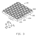
FIG. 3 is an isometric view of the prism sheet of FIG. 1, as seen from a top aspect.
FIG. 4 is a bottom plan view of an optical plate according to a second preferred embodiment of the present invention.
FIG. 5 is a side cross-sectional view of a conventional backlight module employing a typical prism sheet.
FIG. 6 is an isometric view of the prism sheet shown in FIG. 5.
FIG. 7 is a side, cross-sectional view of the prism sheet of FIG. 5, taken along line VII-VII, showing light transmission paths.
DETAILED DESCRIPTION OF THE PREFERRED EMBODIMENTS
Reference will now be made to the drawings to describe preferred embodiments of the present prism sheet and backlight module, in detail.
Referring to FIG. 1, a backlight module 200 in accordance with a first preferred embodiment of the present invention is shown. The backlight module 200 includes a prism sheet 20, a light diffusion plate 21, a plurality of lamps 22 and a housing 23. The lamps 22 are regularly aligned above a base of the housing 23. The light diffusion plate 21 and the prism sheet 20 are stacked on the top of the housing 23 in that order.
The prism sheet 20 includes a transparent main body. The main body includes a first surface 201, a second surface 203, a plurality of spherical depressions 202, a plurality of triangular pyramidal depressions 204 and a plurality of hexagonal pyramidal depressions 205. The first surface 201 and the second surface 203 are on opposite sides of the main body. The first surface 201 is adjacent to the light diffusion plate 23, and the second surface 203 faces away from the light diffusion plate 23. The spherical depressions 202 are formed in the first surface 201. The triangular pyramidal depressions 204 and the hexagonal pyramidal depressions 205 are formed in the second surface 203. Each triangular pyramidal depression 204 is surrounded by three adjacent hexagonal pyramidal depressions 205 correspondingly.
Referring to FIGS. 1 and 2, the spherical depressions 202 are distributed on the first surface 201 in a matrix manner. The spherical depressions 202 are configured for converging incident light from the lamps 22 to a certain extent. Rows and columns of the spherical depressions 202 in the matrix are parallel to the edges of the prism sheet 20 (along an X-direction and a Z-direction) correspondingly. A pitch P1 between centers of adjacent spherical depressions 202 can be configured to be in a range from about 0.025 millimeters to about 1.5 millimeters. A radius R of a sphere defined by each spherical depression 202 is in a range satisfying the following expression: P1/4≦R ≦P1/2. In other words, the radius R of the sphere defined by each spherical depression 202 can be in a range from about 0.01 millimeters to about 0.75 millimeters. A depth H of each spherical depression 202 is configured to be in a range satisfying the following expression: 0.01 millimeters≦H≦R. In the first embodiment, the depth H of each spherical depression 202 is equal to the radius R. The pitch P1 between adjacent spherical depressions 202 is equal to a diameter of each spherical depression 202.
Referring to FIG. 3, the distribution and structures of the triangular pyramidal depressions 204 and the hexagonal pyramidal depressions 205 are configured for converging light from the second surface 203. In this embodiment, each triangular pyramidal depression 204 is an equilateral triangular pyramid in shape. Each hexagonal pyramidal depression 205 is an equilateral hexagonal pyramid in shape. A dihedral angle defined by opposite side surfaces of each of the hexagonal pyramidal depressions can be configured to be in a range from about 50 degrees to about 120 degrees. In addition, a plurality of ridges 207 are defined by adjacent triangular pyramidal depressions 204 and hexagonal pyramidal depressions 205 correspondingly. The ridges 207 mainly extend along three directions in a same plane, such as a X1-direction, a X2-direction and a X3-direction. Angles θ1, θ2, and θ3 defined by X1-X2 direction, X2-X3 direction, and X3-X1 direction can be 120 degrees correspondingly. A pitch P2 between center line of adjacent ridges 207 in a same direction is in a range from 0.025 millimeters to 1 millimeter.
A thickness of the prism sheet 20 is preferably in the range from about 0.5 millimeters to about 3 millimeters. The prism sheet 20 can be made of transparent material selected from the group consisting of polycarbonate (PC), polymethyl methacrylate (PMMA), polystyrene (PS), copolymer of methylmethacrylate and styrene (MS), and any suitable combination thereof.
Again referring to FIG. 1, the lamps 22 can be point light sources or linear light sources, such as light emitting diodes or cold cathode fluorescent lamps. In the first embodiment, the lamps 22 are cold cathode fluorescent lamps. The housing 23 is made of metal or plastic materials. An interior of the housing 23 is configured to be highly reflective.
In the backlight module 200, when the light enters the prism sheet 20 via the first surface 201, the light is converged to a certain extent by the spherical depressions 202 of the first surface 201. Then the light is further substantially converged by the triangular pyramidal depressions 204 and hexagonal pyramidal depressions 205 of the second surface 203 when exiting the prism sheet 20. Therefore, a brightness of the backlight module 200 is increased. In addition, with the help of the triangular pyramidal depressions 204 and hexagonal pyramidal depressions 205, many or most of the light would propagate along directions closely parallel to the Y-direction. At the same time, less light would travel along directions close to the X-direction, resulting in decreasing the consumption of light energy. Accordingly, the light energy utilization rate of the backlight module 200 is increased.
Furthermore, the first surface 201 forms spherical depression 202 having curved sidewalls, thus a light receiving area of the sheet 20 is increased. Because the second surface 203 forms depressions having sidewalls expanding out of the prism sheet 20 at an angle, the angle that the light refracts out (allowing the light to exit) of the prism sheet 20 is expanded. Additionally, the slope of the sidewalls of the triangular pyramidal depressions 204 or the hexagonal pyramidal depressions 205, and also the obliqueness relative to the edge of the prism sheet 20 can have various configurations according to predetermined viewing angles requirements of the backlight module 200. The prism sheet 20 can also be orientated to obtain appropriate viewing angle thereby satisfying most of the LCD displays' requirements on horizontal and vertical viewing angles. Additionally, if the backlight module 200 is used in a liquid crystal display device, an arrangement of the triangular pyramidal depressions 204 and hexagonal pyramidal depressions 205 would be different from that of pixels of the liquid crystal display panel. Thus moiré pattern interference caused by the prism sheet 20 and the pixel pitch of the liquid crystal display panel 25 is kept minimal or eliminated.
Moreover, when compared to the conventional prism sheet, the prism sheet 20 of the present invention is integrally formed by injection molding technology. Thus, it is easier to mass-produce the prism sheet 20 via the injection molding method. Because the prism lenses of the conventional prism sheet is solidified by melted ultraviolet-cured transparent resin, the prism lenses are usually damaged or scraped due to their poor rigidity and mechanical strength. When compared to the conventional prism sheet, the prism sheet 20 has a better rigidity and mechanical strength. Therefore, the present prism sheet is not easily damaged or scratched.
Referring to FIG. 4, a prism sheet 30 in accordance with a second preferred embodiment of the present invention is shown. The prism sheet 30 is similar in principle to the prism sheet 20. However, spherical depressions 302 are aligned side by side on a first surface 301 of the prism sheet 30 in rows. Adjacent spherical depressions 302 in each row adjoin each other. The spherical depressions 302 in any two adjacent rows are staggered relative to each other and abut each other. Thus a matrix comprised of offset rows of the spherical depressions 302 is formed. In another words, a honeycomb pattern of the spherical depressions 302 is formed.
It is noted that the scope of the present prism sheet and backlight module is not limited to the embodiments described above. For example, in the prism sheet 20, the spherical depressions 202 can be aligned apart, be arranged randomly or be arranged symmetrically relative a center of the prism sheet 20. The rows and the columns of the spherical depressions 202 in the matrix can be aligned obliquely to the edges of the prism sheet 20. The triangular pyramidal depressions 204 and hexagonal pyramidal depressions 205 can be aligned apart.
Finally, while various embodiments have been described and illustrated, the invention is not to be construed as being limited thereto. Various modifications can be made to the embodiments by those skilled in the art without departing from the true spirit and scope of the invention as defined by the appended claims.

Claims (18)

1. A prism sheet comprising:
a transparent main body having:
a first surface,
a second surface opposite to the first surface,
a plurality of spherical depressions formed in the first surface; and
a plurality of triangular pyramidal depressions and hexagonal pyramidal depressions formed in the second surface, each of the triangular pyramidal depressions surrounded by three adjacent hexagonal pyramidal depressions.
2. The prism sheet according to claim 1, wherein a pitch between adjacent spherical depressions is in a range from about 0.025 millimeters to about 1.5 millimeters.
3. The prism sheet according to claim 1, wherein a radius of each spherical depression is in a range from about 0.01 millimeters to about 0.75 millimeters.
4. The prism sheet according to claim 1, wherein a depth of each spherical depression is equal to or greater than about 0.01 millimeters and equal to or less than a radius of each spherical depression.
5. The prism sheet according to claim 1, wherein the spherical depressions are distributed at the first surface in a matrix manner.
6. The prism sheet according to claim 1, wherein each triangular pyramidal depression is an equilateral triangular pyramid in shape, and each hexagonal pyramidal depression is an equilateral hexagonal pyramid in shape.
7. The prism sheet according to claim 1, wherein a dihedral angle defined by opposite side surfaces of each of the hexagonal pyramidal depressions is configured to be in a range from about 50 degrees to about 120 degrees.
8. The prism sheet according to claim 1, wherein a thickness of the prism sheet is in a range from about 0.5 millimeters to about 3 millimeters.
9. The prism sheet according to claim 1, wherein the prism sheet is made of transparent material selected from the group consisting of polycarbonate, polymethyl methacrylate, polystyrene, copolymer of methylmethacrylate and styrene, and any combination thereof.
10. A backlight module comprising:
a plurality of lamps;
a light diffusion plate disposed above the lamps; and
a prism sheet disposed on the light diffusion plate, the prism sheet includes a transparent main body having
a first surface,
a second surface opposite to the first surface, and
a plurality of spherical depressions formed in the first surface; and
a plurality of triangular pyramidal depressions and hexagonal pyramidal depressions formed in the second surface, each of the triangular pyramidal depressions surrounded by three adjacent hexagonal pyramidal depressions.
11. The backlight module according to claim 10, wherein the first surface of the prism sheet faces the light diffusion plate.
12. The backlight module according to claim 10, wherein a pitch between adjacent spherical depressions is in a range from about 0.025 millimeters to about 1.5 millimeters.
13. The backlight module according to claim 10, wherein a radius of each spherical depression is in a range from about 0.01 millimeters to about 0.75 millimeters.
14. The backlight module according to claim 10, wherein a depth of each spherical depression is equal to or greater than about 0.01 millimeters and equal to or less than a radius of each spherical depression.
15. The backlight module according to claim 10, wherein the spherical depressions are distributed at the first surface in a matrix manner.
16. The backlight module according to claim 10, wherein each triangular pyramidal depression is an equilateral triangular pyramid in shape, and each hexagonal pyramidal depression is an equilateral hexagonal pyramid in shape.
17. The backlight module according to claim 10, wherein a dihedral angle defined by opposite side surfaces of each of the hexagonal pyramidal depressions is configured to be in a range from about 50 degrees to about 120 degrees.
18. The backlight module according to claim 10, wherein a thickness of the prism sheet is in a range from about 0.5 millimeters to about 3 millimeters.
US11/949,059 2007-09-17 2007-12-03 Prism sheet and backlight module using the same Expired - Fee Related US7656597B2 (en)

Applications Claiming Priority (3)

Application Number Priority Date Filing Date Title
CN200710201741 2007-09-17
CN2007102017416A CN101393279B (en) 2007-09-17 2007-09-17 Back light module unit and prismatic lens thereof
CN200710201741.6 2007-09-17

Publications (2)

Publication Number Publication Date
US20090073565A1 US20090073565A1 (en) 2009-03-19
US7656597B2 true US7656597B2 (en) 2010-02-02

Family

ID=40454173

Family Applications (1)

Application Number Title Priority Date Filing Date
US11/949,059 Expired - Fee Related US7656597B2 (en) 2007-09-17 2007-12-03 Prism sheet and backlight module using the same

Country Status (2)

Country Link
US (1) US7656597B2 (en)
CN (1) CN101393279B (en)

Cited By (2)

* Cited by examiner, † Cited by third party
Publication number Priority date Publication date Assignee Title
US20100002416A1 (en) * 2008-07-04 2010-01-07 Hon Hai Precision Industry Co., Ltd. Optical plate and backlight module using the same
US20110182083A1 (en) * 2007-08-09 2011-07-28 Nec Lighting, Ltd. Illuminating device

Families Citing this family (10)

* Cited by examiner, † Cited by third party
Publication number Priority date Publication date Assignee Title
DE202010002744U1 (en) * 2010-02-24 2010-07-08 Bwf Kunststoffe Gmbh & Co. Kg Device for glare-reduced coupling of light
JP5652192B2 (en) * 2010-12-20 2015-01-14 セイコーエプソン株式会社 Clock dial and clock
JP5741114B2 (en) * 2010-12-27 2015-07-01 セイコーエプソン株式会社 Clock dial and clock
CN102955420B (en) * 2011-08-18 2015-08-26 精工爱普生株式会社 The manufacture method of dial for timepiece, dial for timepiece and clock and watch
EP2562608A3 (en) * 2011-08-25 2016-12-28 Seiko Epson Corporation Timepiece dial and timepiece
JP2013061190A (en) * 2011-09-12 2013-04-04 Seiko Epson Corp Dial for timepiece, and timepiece
US20130070574A1 (en) * 2011-09-15 2013-03-21 Seiko Epson Corporation Timepiece rotating display member, and timepiece
CN107102387A (en) * 2017-05-17 2017-08-29 常州丰盛光电科技股份有限公司 Anti-dazzle tabula rasa and its forming method for preparing mould and mould
US11131883B2 (en) * 2018-06-22 2021-09-28 Minebea Mitsumi Inc. Planar lighting device
CN112768541A (en) * 2020-12-31 2021-05-07 彩虹集团新能源股份有限公司 Six pyramid anti-dazzle decorative pattern structures of photovoltaic calendering glass

Citations (9)

* Cited by examiner, † Cited by third party
Publication number Priority date Publication date Assignee Title
US3716710A (en) * 1969-04-21 1973-02-13 Trilux Lenze Gmbh & Co Kg Lamp comprising an elongated light source,particularly a rod-shaped fluorescent lamp,and shade of transparent material
US3764800A (en) * 1972-10-17 1973-10-09 Trilux Lenze Gmbh & Co Kg Cover plate for a lamp
US4851164A (en) * 1983-11-26 1989-07-25 Olympus Optical Company Limited Method of manufacturing focal plates
JPH07114025A (en) 1993-10-20 1995-05-02 Sharp Corp Liquid crystal display device
US6275338B1 (en) * 1994-03-29 2001-08-14 Enplas Corporation Light regulation device
US20020145860A1 (en) 2001-04-09 2002-10-10 Hea-Chun Lee Backlight assembly and liquid crystal display device using thereof
CN1504776A (en) 2002-12-05 2004-06-16 鸿富锦精密工业(深圳)有限公司 Light conducting element
US20060172119A1 (en) * 2003-07-24 2006-08-03 Masahiko Hayashi Reflection preventing molding and method of manufacturing the same
US20070014034A1 (en) * 2005-07-15 2007-01-18 Chi Lin Technology Co., Ltd. Diffusion plate used in direct-type backlight module and method for making the same

Patent Citations (9)

* Cited by examiner, † Cited by third party
Publication number Priority date Publication date Assignee Title
US3716710A (en) * 1969-04-21 1973-02-13 Trilux Lenze Gmbh & Co Kg Lamp comprising an elongated light source,particularly a rod-shaped fluorescent lamp,and shade of transparent material
US3764800A (en) * 1972-10-17 1973-10-09 Trilux Lenze Gmbh & Co Kg Cover plate for a lamp
US4851164A (en) * 1983-11-26 1989-07-25 Olympus Optical Company Limited Method of manufacturing focal plates
JPH07114025A (en) 1993-10-20 1995-05-02 Sharp Corp Liquid crystal display device
US6275338B1 (en) * 1994-03-29 2001-08-14 Enplas Corporation Light regulation device
US20020145860A1 (en) 2001-04-09 2002-10-10 Hea-Chun Lee Backlight assembly and liquid crystal display device using thereof
CN1504776A (en) 2002-12-05 2004-06-16 鸿富锦精密工业(深圳)有限公司 Light conducting element
US20060172119A1 (en) * 2003-07-24 2006-08-03 Masahiko Hayashi Reflection preventing molding and method of manufacturing the same
US20070014034A1 (en) * 2005-07-15 2007-01-18 Chi Lin Technology Co., Ltd. Diffusion plate used in direct-type backlight module and method for making the same

Cited By (3)

* Cited by examiner, † Cited by third party
Publication number Priority date Publication date Assignee Title
US20110182083A1 (en) * 2007-08-09 2011-07-28 Nec Lighting, Ltd. Illuminating device
US20100002416A1 (en) * 2008-07-04 2010-01-07 Hon Hai Precision Industry Co., Ltd. Optical plate and backlight module using the same
US7993020B2 (en) * 2008-07-04 2011-08-09 Hon Hai Precision Industry Co., Ltd. Optical plate having triangular pyramidal depressions and backlight module using the same

Also Published As

Publication number Publication date
US20090073565A1 (en) 2009-03-19
CN101393279A (en) 2009-03-25
CN101393279B (en) 2010-12-01

Similar Documents

Publication Publication Date Title
US7656597B2 (en) Prism sheet and backlight module using the same
US7628514B2 (en) Prism sheet and backlight module using the same
US7445361B1 (en) Prism sheet and backlight module using the same
US7753565B2 (en) Prism sheet and backlight module the same
US7726827B2 (en) Prism sheet and backlight module using the same
US8061877B2 (en) Prism sheet having parallelogram microstructures
US7914179B2 (en) Optical plate with V-shaped protrusions on both sides and backlight module using the same
US7753543B2 (en) Prism sheet and backlight module using the same
US20140104871A1 (en) Light management film
JP2008139878A (en) Optical plate
US7637645B2 (en) Prism sheet and backlight module using the same
US20090097245A1 (en) Prism sheet and backlight module using the same
US20080137196A1 (en) Optical plate having three layers and backlight module with same
US20090073723A1 (en) Prism sheet and backlight module using the same
US7744245B2 (en) Prism sheet and backlight module using the same
US7845811B2 (en) Prism sheet and liquid crystal display device using the same
US7969655B2 (en) Prism sheet
US20080137200A1 (en) Optical plate having three layers and backlight module with same
US20090080220A1 (en) Prism sheet and backlight module using the same
US20080130116A1 (en) Optical plate having three layers and backlight module with same
US7845810B2 (en) Prism sheet and liquid crystal display device using the same
US8256932B2 (en) Light diffusion plate and backlight module using the same
US20080137201A1 (en) Optical plate having three layers and backlight module with same
US20090116219A1 (en) Prism sheet and backlight module using the same
US7712945B2 (en) Prism sheet and backlight module using the same

Legal Events

Date Code Title Description
AS Assignment

Owner name: HON HAI PRECISION INDUSTRY CO., LTD., TAIWAN

Free format text: ASSIGNMENT OF ASSIGNORS INTEREST;ASSIGNORS:HSU, TUNG-MING;CHANG, SHAO-HAN;REEL/FRAME:020184/0141

Effective date: 20071126

Owner name: HON HAI PRECISION INDUSTRY CO., LTD.,TAIWAN

Free format text: ASSIGNMENT OF ASSIGNORS INTEREST;ASSIGNORS:HSU, TUNG-MING;CHANG, SHAO-HAN;REEL/FRAME:020184/0141

Effective date: 20071126

FPAY Fee payment

Year of fee payment: 4

FEPP Fee payment procedure

Free format text: MAINTENANCE FEE REMINDER MAILED (ORIGINAL EVENT CODE: REM.)

LAPS Lapse for failure to pay maintenance fees

Free format text: PATENT EXPIRED FOR FAILURE TO PAY MAINTENANCE FEES (ORIGINAL EVENT CODE: EXP.)

STCH Information on status: patent discontinuation

Free format text: PATENT EXPIRED DUE TO NONPAYMENT OF MAINTENANCE FEES UNDER 37 CFR 1.362

FP Expired due to failure to pay maintenance fee

Effective date: 20180202