US7653699B1 - System and method for partitioning a file system for enhanced availability and scalability - Google Patents
System and method for partitioning a file system for enhanced availability and scalability Download PDFInfo
- Publication number
- US7653699B1 US7653699B1 US10/460,148 US46014803A US7653699B1 US 7653699 B1 US7653699 B1 US 7653699B1 US 46014803 A US46014803 A US 46014803A US 7653699 B1 US7653699 B1 US 7653699B1
- Authority
- US
- United States
- Prior art keywords
- file
- systems
- file system
- physical
- metadata
- Prior art date
- Legal status (The legal status is an assumption and is not a legal conclusion. Google has not performed a legal analysis and makes no representation as to the accuracy of the status listed.)
- Active, expires
Links
Images


Classifications
-
- G—PHYSICS
- G06—COMPUTING; CALCULATING OR COUNTING
- G06F—ELECTRIC DIGITAL DATA PROCESSING
- G06F16/00—Information retrieval; Database structures therefor; File system structures therefor
- G06F16/10—File systems; File servers
Definitions
- This invention is related to the field of storage management and, more particularly, to management of distributed storage in a multi-server environment.
- the first trend is a movement away from storage being directly attached to servers and towards storage being network attached.
- this network-attached storage may be directly accessible by clients.
- Enterprise computing environments are increasingly using configurations such as computer clusters, Storage Area Networks (SANs), Network Attached Storage (NAS), and other centralized storage mechanisms to simplify storage, improve availability, and handle escalating demands for data and applications.
- SANs Storage Area Networks
- NAS Network Attached Storage
- Clustering may be defined as the use of multiple computers (e.g., PCs or UNIX workstations), multiple storage devices, and redundant interconnections to form what appears to external users as a single and highly available system. Clustering may be used for load balancing and parallel processing as well as for high availability.
- the storage area network (SAN) model places storage on its own dedicated network, removing data storage from the main user network.
- This dedicated network most commonly uses Fibre Channel technology as a versatile, high-speed transport.
- the SAN includes one or more hosts that provide a point of interface with LAN users, as well as (in the case of large SANs) one or more fabric switches, SAN hubs and other devices to accommodate a large number of storage devices.
- the hardware e.g. fabric switches, hubs, bridges, routers, cables, etc.
- the SAN fabric may enable server-to-storage device connectivity through Fibre Channel switching technology to a wide range of servers and storage devices.
- the versatility of the SAN model enables organizations to perform tasks that were previously difficult to implement, such as LAN-free and server-free tape backup, storage leasing, and full-motion video services.
- SAN deployment promises numerous advantages, including cost management through storage consolidation, higher availability of data, better performance and seamless management of online and offline data.
- the LAN is relieved of the overhead of disk access and tape backup, data availability becomes less server-dependent, and downtime incurred by service and maintenance tasks affects more granular portions of the available storage system.
- server appliances which include an aggregation of inexpensive server modules.
- These server modules are typically not of very high capacity, but the appliance can be scaled to meet the performance requirements by aggregating multiple such modules.
- Customers may start with a configuration which meets their current requirements and later add capacity as needed. To minimize administrative overhead, such an appliance may look and behave like a traditional file server.
- This metadata bottleneck may be present in other network storage configurations, and it may limit the usability of large file systems.
- extremely large file systems may demand unacceptably large times for file system consistency check (“fsck”) operations.
- fsck file system consistency check
- an entire file system may be offline for hours while undergoing an fsck operation. It is therefore desirable to improve the performance and availability of file systems during file system metadata operations such as consistency checks.
- the system may include one or more server computer systems and a plurality of physical file systems.
- the physical file systems may be hosted by the one or more server computer systems.
- the physical file systems may be accessible to clients through a virtual file system having a namespace.
- the virtual file system may include metadata which are partitioned across the plurality of physical file systems.
- the server computer systems may be configured to independently perform file system consistency checks on each of the physical file systems, in order to independently validate each partition of the metadata.
- FIG. 1 illustrates an exemplary enterprise computing system with which embodiments of a system and method for partitioning a file system may be implemented.
- FIG. 2 illustrates an exemplary client computer system with which embodiments of a system and method for partitioning a file system may be implemented.
- FIG. 3 illustrates an architecture of software and/or hardware components of computer systems configured to provide and access a virtual file system according to one embodiment.
- FIG. 4 illustrates a relationship between a virtual file system and underlying physical file systems according to one embodiment.
- FIG. 5 illustrates an exemplary configuration of a client which is configured to re-export a virtual file system according to one embodiment.
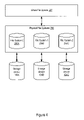
- FIG. 6 illustrates an exemplary partitioning of inode address space in a partitioned file system according to one embodiment.
- FIG. 7 illustrates an exemplary representation of remote files in a partitioned file system according to one embodiment.
- FIG. 8 is a flowchart which illustrates a method for client-server interaction in a virtual file system according to one embodiment.
- FIGS. 9A , 9 B, and 9 C illustrate examples of virtualization and migration of inodes in a partitioned file system according to one embodiment.
- FIGS. 9D and 9E illustrate an example of migration of inodes in a partitioned file system according to one embodiment.
- FIG. 10 is a flowchart which illustrates a method for partitioning a file system to distribute the load of performing file system consistency checks according to one embodiment.
- FIG. 1 illustrates an exemplary enterprise computing system with which embodiments of a system and method for partitioning a file system may be implemented.
- FIG. 1 will be discussed herein in the context of a Storage Area Network (SAN) environment, the configuration shown in FIG. 1 is meant to be an exemplary embodiment of a networked storage configuration.
- Other networked storage configurations including (but not limited to) a cluster, a NAS (Network Attached Storage) system, and other SAN configurations, may be used with embodiments of the system and method for partitioning a file system as described herein.
- the SAN may be described as a high-speed, special-purpose network that interconnects one or more storage devices 104 (e.g. storage devices 104 A, 104 B, and 104 C) with one or more associated host systems or servers 102 on behalf of a larger network of users.
- This dedicated network may employ Fibre Channel technology.
- a SAN may be part of the overall network of computing resources for an enterprise or other entity.
- the one or more servers 102 and one or more storage devices 104 (e.g. storage devices 104 A, 104 B, and 104 C) may be coupled via a fabric 100 .
- One or more client systems 106 may access the SAN by accessing one or more of the servers 102 via a network 108 .
- the client systems 106 may communicate with the server 102 to access data on the storage devices 104 A, 104 B, and 104 C which are managed by server 102 .
- the client systems 106 may comprise server systems which manage a different set of storage devices.
- the client systems 106 may therefore also act as servers and may be coupled to other storage devices (not shown) through the fabric 100 .
- the server(s) 102 may present a single, global namespace to the clients 106 , wherein the global namespace includes the individual namespaces from storage devices 104 .
- Network 108 may include wired or wireless communications connections separate from the Fibre Channel network.
- network 108 is representative of any local area network (LAN) such as an intranet or any wide area network (WAN) such as the Internet.
- Network 108 may use a variety of wired or wireless connection mediums.
- wired mediums may include: a modem connected to “plain old telephone service” (POTS), Ethernet, and fiber channel.
- POTS plain old telephone service
- Wireless connection mediums include a satellite link, a modem link through a cellular service or a wireless link such as Wi-FiTM, for example.
- Storage devices may include any of one or more types of storage devices including, but not limited to, storage systems such as RAID (Redundant Array of Independent Disks) systems, disk arrays, JBODs (Just a Bunch Of Disks, used to refer to disks that are not configured according to RAID), tape devices, and optical storage devices. These devices may be products of any of a number of vendors including, but not limited to, Compaq, EMC, and Hitachi.
- Clients 106 and server 102 may run any of a variety of operating systems, including, but not limited to, Solaris 2.6, 7 or 8, Microsoft Windows NT 4.0 (Server and Enterprise Server), Microsoft Windows 2000 (Server, Advanced Server and Datacenter Editions), and various versions of HP-UX.
- Each server 102 may be connected to the fabric 100 via one or more Host Bus Adapters (HBAs).
- HBAs Host Bus Adapters
- the hardware that connects servers 102 to storage devices 104 in a SAN may be referred to as a fabric 100 .
- the fabric 100 enables server-to-storage device connectivity through Fibre Channel switching technology.
- the fabric 100 hardware may include one or more switches (also referred to as fabric switches), bridges, hubs, or other devices such as routers, as well as the interconnecting cables (for Fibre Channel SANs, fibre optic cables).
- Fabric 100 may include one or more distinct device interconnection structures (e.g. Fibre Channel Arbitrated Loops, Fibre Channel Fabrics, etc.) that collectively form the fabric 100 .
- a SAN-aware file system may use the Network File System (NFS) protocol in providing access to shared files on the SAN.
- NFS Network File System
- each server 102 may include a logical hierarchy of files (i.e., a directory tree) physically stored on one or more of storage devices 104 and accessible by the client systems 106 through the server 102 .
- These hierarchies of files, or portions or sub-trees of the hierarchies of files may be referred to herein as “file systems.”
- the SAN components may be organized into one or more clusters to provide high availability, load balancing and/or parallel processing. For example, in FIG. 1 , server 102 and clients 106 A and 106 B may be in a cluster.
- each server is privately connected to one or more storage devices using SCSI or other storage interconnect technology. If a server is functioning as a file server, it can give other servers (its clients) on the network access to its locally attached files through the local area network. With a storage area network, storage devices are consolidated on their own high-speed network using a shared SCSI bus and/or a fibre channel switch/hub.
- a SAN is a logical place to host files that may be shared between multiple systems.
- a shared storage environment is one in which multiple servers may access the same set of data.
- a common architecture for sharing file-based storage is the File Server architecture, for example, the SAN environment illustrated in FIG. 1 .
- the File Server architecture one or more servers are connected to a large amount of storage (either attached locally or in a SAN) and provide other systems access to this storage.
- FIG. 2 illustrates an exemplary client computer system (“client”) 106 with which embodiments of a system and method for partitioning a file system may be implemented.
- client client computer system
- the client 106 may access a global namespace which includes a plurality of individual namespaces.
- the client computer system 106 may include various hardware and software components.
- the client computer system 106 includes a processor 220 A coupled to a memory 230 which is in turn coupled to storage 240 .
- processor 220 A is coupled to a network interface 260 .
- the client computer system 106 may be connected to a network such as network 108 via a network connection 275 . Further, the client computer system 106 includes operating system software 130 .
- the operating system software 130 is executable by processor 220 A out of memory 230 A, typically to perform basic tasks (e.g., input/output tasks).
- the operating system software 130 may include client-side virtualization software 250 as will be discussed in greater detail below. In another embodiment, the client-side virtualization software 250 may logically reside on top of the operating system software 130 .
- Processor 220 A may be configured to execute instructions and to operate on data stored within memory 230 A.
- processor 220 A may operate in conjunction with memory 230 A in a paged mode, such that frequently used pages of memory may be paged in and out of memory 230 A from storage 240 according to conventional techniques.
- processor 220 A is representative of any type of processor.
- processor 220 A may be compatible with the x86 architecture, while in another embodiment processor 220 A may be compatible with the SPARCTM family of processors.
- Memory 230 A is configured to store instructions and data.
- memory 230 A may be implemented in various forms of random access memory (RAM) such as dynamic RAM (DRAM) or synchronous DRAM (SDRAM).
- RAM random access memory
- DRAM dynamic RAM
- SDRAM synchronous DRAM
- DRAM dynamic RAM
- SDRAM synchronous DRAM
- Storage 240 is configured to store instructions and data.
- Storage 240 is illustrative of any type of mass storage device or system.
- storage 240 may be implemented as one or more hard disks configured independently or as a disk storage system.
- the disk storage system may be a redundant array of inexpensive disks (RAID) system.
- the disk storage system may be a disk array, or Just a Bunch Of Disks (JBOD), (used to refer to disks that are not configured according to RAID).
- storage 240 may include tape drives, optical storage devices or RAM disks, for example.
- Network interface 260 may implement functionality to connect the client computer system 106 to a network such as network 108 via network connection 275 .
- network interconnect 260 may include a hardware layer and a software layer which controls the hardware layer.
- the software may be executable by processor 220 A out of memory 230 A to implement various network protocols such as TCP/IP and hypertext transport protocol (HTTP), for example.
- TCP/IP Transmission Control Protocol/Internet Protocol
- HTTP hypertext transport protocol
- FIGS. 1 and 2 illustrate typical computer system and network storage architectures in which embodiments of the system and method for partitioning a file system as described herein may be implemented, embodiments may be implemented in other computer and network storage architectures.
- FIG. 3 illustrates an architecture of software and/or hardware components of computer systems configured to provide and access a virtual file system according to one embodiment.
- a file server environment As the size of the file system grows and the load on the file system increases, a single server managing all the metadata operations for a given file system is likely to become a bottleneck. Because the load on a file system is a result of operations done on objects (e.g., files) in its namespace, it may be assumed that by partitioning the namespace of a file system amongst multiple servers 102 , the load on the file system may also be partitioned.
- objects e.g., files
- the file system metadata load is distributed amongst a plurality of servers 102 by partitioning the namespace of a file system amongst those servers while maintaining a single file system image and semantics.
- This approach for improving file system metadata scalability may be referred to generally as namespace virtualization. As the file system grows in size, and as the number of clients 106 increases, this approach allows the enterprise to handle the increased metadata load by adding servers 102 and redistributing the namespace amongst them.
- Embodiments of each of the server systems 102 A and 102 B may be similar to the client system 106 illustrated in FIG. 2 .
- the server system 102 A may include a processor 220 B coupled to a memory 230 B which is in turn coupled to optional storage.
- the server system 102 B may include a processor 220 C coupled to a memory 230 C which is in turn coupled to optional storage.
- the server computer systems 102 A and 102 B may be connected to a network via a network connection.
- the server computer systems 102 A and 102 B may include operating system and/or server software which is executable by the respective processors out of the respective memories.
- the server systems 102 A and 102 B may “own” or manage data objects (e.g., files) on one or more storage devices 104 .
- the server systems 102 A and 102 B may execute file server software to control access to the data they owns.
- the server functionality may be implemented in hardware and/or firmware.
- a file server “appliance,” implemented using multiple servers 102 as nodes, may be configured to export a single file system image.
- the appliance may internally partition the namespace of this file system amongst a plurality of constituent file systems.
- Responsibility for performing the metadata operations for each file system may be distributed amongst the server nodes 102 of the appliance.
- the appliance may be implemented in a variety of ways.
- the appliance may comprise a cluster of servers 102 with shared storage 104 .
- File systems may be mounted by more than one server 102 , but the primaryship for each file system may be distributed amongst the server nodes 102 .
- Clients 106 may communicate using standard NFS and/or CIFS protocols.
- the appliance may comprise a set of servers 102 , where each server 102 manages one or more file systems. Storage may be shared between clients 106 and servers 102 . Custom software on the clients 106 may allow direct access to storage. In this case, clients 106 may communicate with servers 102 using proprietary protocols.
- the server 102 A and/or server 102 B may take the form of a block-server appliance (e.g., on a SAN).
- Storage devices are usually designed to provide data to servers 102 using one of two methods, either block-level or file-level access.
- Block I/O is typically the I/O which is tied directly to the disks 104 .
- Block I/O is typically used when direct and fast access to the physical drives themselves is required by the client application.
- the client 106 may request the data from the block server 102 using the starting location of the data blocks and the number of blocks to be transferred.
- the operating system 130 on the client 106 may provide a file system to help translate the block locations into file locations.
- connections 109 A and 109 B between the servers 102 A and 102 B, respectively, and the client 106 may comprise a channel protocol such as SCSI or fibre channel.
- the channel protocol may also be connected directly to disks or disk controllers (e.g., RAID controllers).
- SCSI and fibre channel may provide a low latency connection with high performance.
- the memory 230 B of the server 102 A may store instructions which are executable by the processor 220 B to implement the method and system for providing a virtual file system as disclosed herein.
- the memory 230 C of the server 102 B may store instructions which are executable by the processor 220 C to implement the method and system for providing a virtual file system as disclosed herein.
- the instructions may include multiple components or layers. For example, device drivers (not shown) may be used for I/O between the servers 102 and the storage devices 104 .
- a client-server protocol layer 252 may include appropriate communication protocols such as NFS, CIFS, proprietary protocols, and/or other suitable protocols for communication between server and client.
- a plurality of physical file systems such as file system zero 256 A, file system one 256 B, and file system two 256 C may be hosted by the servers.
- a virtualization layer 254 may include instructions to export a global, unified namespace including the namespaces of the various physical file systems 256 .
- the namespace may be partitioned amongst the file systems in a flexible way, such that the namespace may be repartitioned if the load characteristics change (e.g., one server becomes overloaded).
- the semantics of a single file system semantics may be maintained for operations involving any file and any directory in the unified namespace.
- Each constituent file system may manage its namespace in a way that is substantially independently of others.
- Existing file system facilities like directories, directory operations, inode numbers and inode reference counts may be used.
- Virtualization-aware clients 106 may understand this layout and may navigate the unified namespace and perform namespace operations.
- a virtualization protocol 253 between servers may allow namespace operations involving two servers to be completed.
- a “namespace” refers to an address space in which every address is unique.
- a “virtual namespace” refers to a higher-level namespace which aggregates a plurality of lower-level namespaces.
- a “physical file system” or “constituent file system” is a traditional file system in which the entire namespace exists on a single volume.
- a “virtual file system” includes a plurality of physical file systems which appear to clients 106 as a single, unified namespace.
- FIG. 4 illustrates a relationship between a virtual file system 257 and underlying physical file systems 256 according to one embodiment. From the client's point of view, the virtual file system 257 is a single file system and namespace which are served from one server and on which all the traditional file system operations are possible. The namespace is distributed amongst multiple physical file systems 256 , possibly on different servers 102 .
- Virtualization software 254 and/or 250 may ensure that this distributed namespace appears as a single connected namespace to clients 106 .
- exporting includes making the file system or namespace usable by one or more clients 106 to perform file system operations.
- FIG. 5 illustrates an exemplary configuration of a virtualization-aware client 106 and a virtualization-unaware client 106 B according to one embodiment.
- an unmodified client 106 B will be running a standard protocol such as NFS or CIFS, sometimes as part of its operating system 130 B.
- NFS non-re-exporting the virtualized file system from a virtualization-aware client 106 over a client-client network link 109 D
- a virtualization-aware client 106 which re-export the file system in this way may be referred to as a “gateway” or “protocol translator” because it translates client requests from the NFS/CIFS protocol to a virtualization-aware protocol used by the servers 102 .
- the virtualization-aware client 106 may use a client-server network link 109 C to transmit the translated client requests and receive results from the server 102 .
- Individual namespaces of physical file systems 256 may be connected together at points where the parent directory of a file resides on a physical file system different from the one containing the file itself.
- directory A may reside on server S 1
- its subdirectory B may reside on server S 2 .
- the client 106 should contact server S 1 when it needs to do a lookup in A, and it should contact server S 2 when it needs to do a lookup in B.
- the client 106 looks up B in A and gets a handle for B, the client 106 should also be instructed that any directory operations on B should be done by contacting server S 2 .
- server S 1 needs to know that B actually resides on server S 2 .
- Namespace virtualization may enable these transactions.
- all servers 102 that provide physical file systems 256 to the virtual file system 257 may run server-side virtualization software such as a virtualization layer 254 .
- These servers 106 may be referred to as “virtualization-aware servers.”
- server-side virtualization software may be implemented primarily as a layer on top of underlying file system software.
- cross file system transactions include operations involving two or more physical file systems such as create, delete, mkdir, rmdir and rename. The most common case of cross file system transactions would be an mkdir operation across two physical file systems 256 .
- a “virtualization server-to-server protocol” 253 is the protocol between two virtualization-aware servers 102 for implementing cross file system transactions.
- the virtual file system 257 includes metadata which are partitioned across the plurality of physical file systems 256 as discussed herein.
- the metadata may include information concerning the origin of data, the location of data, the hierarchy of data, and other relevant information.
- the metadata may be checked and/or validated using an operation referred to herein as a file system consistency check (“fsck”).
- fsck file system consistency check
- the metadata may include well-known data types such as inodes as well as other data structures such as inode lists.
- a unique and persistent inode number may be associated with each file and presented to the clients of the virtual file system 257 . Therefore, any mechanism to associate inode numbers with files should guarantee the uniqueness of inode numbers across multiple physical file systems. The mechanism may further guarantee that the inode number does not change when a file migrates between physical file systems 256 .
- the virtual namespace may include a representation for directory entries which point to remote files.
- the virtual namespace may also include a representation for “..” of directories for cases where the parent directory is remote.
- the virtual namespace may maintain the link count for a directory even if it has remote subdirectories and/or a remote parent directory. Similarly, the reference count for a file may be correctly maintained even if one or more of its parent directories are remote.
- inode numbers may be 64 bits.
- the inode address space includes 2 64 possible inode numbers from inode number 0 to inode number 2 64 ⁇ 1.
- the inode address space includes 2 n possible inode numbers.
- this inode address space may be divided amongst the physical file systems 256 in the virtual file system 257 . Ways of partitioning the inode address space may vary.
- the virtual namespace may support a maximum of 256 physical file systems, and the inode address space may be partitioned into 256 equal ranges, where each range includes 2 56 possible inode numbers.
- Each physical file system may exclusively control one such range. In this example, because the physical file systems operate on mutually exclusive ranges, uniqueness of the inode numbers for each file system may be guaranteed.
- FIG. 6 illustrates an exemplary partitioning of inode address space in a partitioned file system according to one embodiment.
- the inode address space for the virtual file system is distributed evenly among each of three physical file systems 256 .
- Each of the physical file systems 256 A, 256 B, and 256 C is assigned a partition amounting to one-third of the inode address space.
- the remainder of the inode address space for a given physical file system 256 may be reserved for “shadowing” inodes of other physical file systems 256 , as will be discussed below.
- a single logical inode list file may be divided up among multiple physical file systems 256 .
- Each file system may maintain its own inode list file as a sparse file and may perform inode allocations only in the designated range.
- physical file system 0 may control the inode address space ⁇ 0 to 2 56 ⁇ 1>
- physical file system 1 may control the inode address space ⁇ 2 56 to 2 57 ⁇ 1>, and so on.
- the virtual file system 257 may use underlying directories of the physical file systems 256 rather than providing a directory structure of its own.
- the same directory may include entries for local and remote files.
- the distinction between local and remote files may be made by the virtual file system 257 based on the inode number of that file.
- the virtual file system 257 may interpret the inode number in a directory entry as a global inode number with the first 8 bits identifying the physical file system.
- physical file system id's may range from 0 to 255.
- a 64 bit inode number may be represented as a tuple ⁇ x, y>, where x represents the first 8 bits, and where y represents the rest of the number.
- x may identify the number of the physical file system.
- a virtualization-aware server on a physical file system 0 may resolve a file name “fileA” to an inode number ⁇ 1, 100>. Because this indicates that the file is remote (it is resident on physical file system 1 ), the server may return the handle to the virtualization client. The client may then contact physical file system 1 to perform the desired operation.
- “fileA” resides on file system 1 , but its parent directory resides on file system 0 . It may be desirable to use physical system structures like the directory to store this hierarchy information. Nevertheless, it may also be desirable to avoid burdening the physical file system with the notion of remote files.
- a “shadow inode” may be locally allocated with the same inode number as the remote file. Note that this shadow inode will be allocated outside the partition of inode address space which is controlled by the local file system. The local file system shadows the remote inode to avoid the potential inconsistency in directory structure if it stored a directory entry for “fileA” but no corresponding inode with that number. This mechanism assists in maintaining the local consistency of the file system.
- the virtual file system lookup may essentially ignore the shadow inode when it is resolving a filename.
- a 64 bit inode number in a directory entry may be interpreted in two ways.
- the underlying physical file system 256 may interpret it as a traditional inode number (e.g., an offset in an inode list).
- the overlying virtual file system 257 may interpret it as a global inode number, where the first 8 bits (for example) identify the particular hosting physical file system 256 .
- FIG. 7 illustrates an exemplary representation of remote files in a partitioned file system according to one embodiment.
- file system 0 maintains a shadow inode for dirX which resides on file system 1
- file system 1 also maintains a shadow inode for dirA which resides on file system 0 .
- FIG. 7 illustrates the combination of two underlying namespaces 261 into a unified “virtual” namespace 262 .
- dirX may be created as a subdirectory of dirA on file system 1 .
- any file with a remote parent directory may be created under the shadow inode of that directory on the local file system.
- Shadow inodes may allow “..” information for directories to be correctly maintained without the virtual file system needing to maintain any extra information.
- shadow inodes may also allow “..” information for regular files to be maintained correctly.
- the virtual file system may handle a lookup on “..” of such files just as it handles any lookup: by mapping the name (“..”) to an inode number and interpreting that inode number as a global inode number.
- Shadow inodes may allow the virtual file system to track reference counts on files correctly without having to maintain them separately from the physical file system. For instance, in the example in shown in FIG. 7 , the reference count on “dirA” is expected to include the “..” reference from its subdirectory “dirX.” Storing a shadow inode for “dirX” permits the reference count on “dirA” to be maintained correctly (from the point of view of the virtual file system).
- the same reference count may be interpreted in two ways.
- the physical file system may interpret it as a local reference to the file/directory.
- the virtual file system may interpret it as a global reference to that file/directory.
- shadow inodes may be distributed amongst a plurality of special directories on each physical file system. These special directories may be hidden from clients making requests through the virtualization layer 254 .
- the file system consistency check (fsck) operation that is native to the underlying physical file systems need not be modified to be virtualization aware.
- the full fsck on fsid N validates the directory “dirA”, it will only verify the existence (locally) of inode number ⁇ 1, 201>.
- the full fsck on file system 1 will only verify that m ode number ⁇ 1, 201> is pointed to by an entry in the directory ⁇ 0, 99>. Therefore, the fsck operation may be performed independently on the underlying physical file systems.
- a high-level fsck may be performed on the virtual namespace to validate the cross file system linkages in the namespace.
- Each physical file system may be offline and unavailable during the individual fsck on its partition of the namespace. However, the entire virtual file system need not be taken offline at the same time.
- the high-level fsck times are proportional to the number of cross links in the namespace. Because the number of cross file system linkages are typically small, the high-level fsck will usually take little time. Namespace virtualization may therefore improve the scalability and availability of a file system for metadata-intensive operations such as file system consistency checks.
- inode allocations are limited to a part of the possible address space. Otherwise, operations that are local to the namespace of a single physical file system need no special handling or modification in one embodiment. These local operations are the bulk of file system operations in a typical network environment.
- Virtualization-aware clients 106 may be provided a handle (in a manner similar to NFS) to identify files when exchanging messages with the server 102 . Clients 106 may acquire these handles by performing lookups. In addition to the handle, a client 106 should be told which physical file system 256 hosts the desired file. In one embodiment, the identity of the hosting physical file system 256 may be embedded in the file handle; in another embodiment, the client 106 may acquire the identity through a separate protocol. The virtualization-aware servers 102 should map the handle to a file.
- FIG. 8 is a flowchart which illustrates a method for client-server interaction in a virtual file system according to one embodiment.
- a client e.g., an unmodified or virtualization-unaware client
- the particular file in the global virtual namespace has a corresponding file identifier (e.g., a unique and persistent inode number) as well as a filename (e.g., ‘A’) and parent directory or path (e.g., ‘B’).
- a modified (i.e., virtualization-aware) client may receive the lookup request from the unmodified client in 313 .
- the modified client may determine which metadata server should be contacted to process the lookup operation in 315 .
- the server may look at the top 8 bits of the inode to determine the appropriate server.
- the appropriate metadata server i.e., the server which hosts the parent directory ‘B’
- the appropriate metadata server may perform a lookup on the directory for filename ‘A’ in 317 .
- the handle of the file may then be returned to the requesting client.
- the client may map this handle to the appropriate physical file system and proceed, for example, by performing a vget operation on that physical file system.
- Virtualization may present a single namespace to clients 106 by distributing the namespace across multiple file systems on multiple servers 102 . As new files are added to the namespace, they may be distributed across multiple file systems to prevent one file system from becoming a bottleneck. In one embodiment, newly created files may be placed on different file systems based on heuristics. These heuristics may take into account factors such as the current metadata load, space utilization, and the fact that a cross file system operation will typically be slower than a local operation. As more files are added and removed, the respective load on different file systems and servers may not remain balanced across the virtualized namespace. The load imbalance may saturate one specific file system and server, thereby resulting in undesirable system performance. To redistribute the load across available servers, the namespace may be repartitioned. Repartitioning may require the migrating of files across physical file systems.
- Migration may be desirable in several scenarios: for example, to address a change in configuration, to address a change in load, for space management, or for administrative convenience.
- the existing configuration may require repartitioning of the namespace after taking into account the new configuration.
- a change in access pattern may require a repartitioning of the namespace in order to achieve optimal performance.
- the load on different parts of the namespace may be quantified. Once the load imbalance is quantified, heuristics may be used to identify subtrees for migration to get better load distribution across the global namespace.
- Extension of a file in the virtual file system may fail if we run out of space on one physical file system even though there is space on other file systems.
- Migration may be useful in balancing the free space across different file systems. If the global namespace can be mapped onto different file systems at a well-defined location (for example, a user's home directory), it may be easier to handle disk failure scenarios. Migration may help in isolating such problems to specific parts of the namespace.
- the virtualization layer 254 may ensure that each file system can generate unique inode numbers. Once an inode number has been allocated to a file, the inode number should remain associated with the file even if the file migrates to a different file system. Therefore, it is not recommended that the inode number contain location information.
- NFS file handles exported by a file system typically contain the inode number along with the generation count. This information may help the file system to quickly locate the inode from the file handle.
- An NFS to virtualization translator may generate mappings from the NFS file handle to the physical file system and the inode number. These mappings may be maintained correctly for migrated files in the virtual file system.
- the virtualization layer makes the migration completely transparent to the applications by keeping the virtual file system consistent.
- a partially completed migration may be rolled back or rolled forward to leave the file system in a consistent state.
- FIGS. 9A , 9 B, and 9 C illustrate examples of virtualization and migration of inodes in a partitioned file system according to one embodiment.
- FIGS. 9A , 9 B, and 9 C show an example of a subtree anchored at “A” containing two subdirectories “B” and “C”.
- the global virtual namespace 262 file system is made up of two namespaces 261 A and 261 B for respective physical file systems FS 0 and FS 1 .
- FIG. 9A illustrates a scenario in which the entire subtree resides on one physical file system.
- FIG. 9B illustrates a scenario in which the subdirectory “C” is created remotely on FS 1 , while the subtree resides on FS 0 .
- the inode number for “C” has the tag 1 to identify the file system where it was created.
- FIG. 9C illustrates a scenario in which subdirectory “C” is created on FS 0 but is migrated to FS 1 .
- the inode number for “C” has tag 0 to identify the file system where it was created.
- the file system where this inode was created controls the allocation and deallocation of this inode number. Because this inode number is still in use (albeit migrated and on some other file system), it is desirable to keep this inode allocated so that its inode number does not get reused and cause consistency problems across the virtual namespace.
- the inode number for “C” (which only contains information about where the file was created) will point to FS 0 . Any client while looking up “C” should be able to determine that the inode resides on FS 1 . In order to achieve this, the corresponding inode on FS 0 should have the correct location information for “C”.
- Location information for migrated files i.e., files that are created on one file system and due to migration reside on some other file system
- the first approach assumes that there would be a few remote files in the virtualized namespace. Whenever an inode needs to be looked up, the search may be started on the file system where the parent directory resides rather than on the file system where the inode was created. In the case of remote files, this heuristic will lead one to search on the wrong file system. At this point, the creator file system information embedded in the inode number (e.g., in the first 8 bits) may be used to locate the file system where the inode resides. This approach has the advantage of simplicity. Nevertheless, it works best when the total number of remote files remains a small percentage of the total virtualized namespace. Locating the file system where a remote file resides may require a trip through the file system where the file was created. This trip may increase the dependency between different components in the system constituting the namespace.
- the location information may be embedded in the directory entry along with the inode number. In this manner, the location of the inode can be found by looking at the information in the directory. As discussed previously, the same inode number should be maintained after migration. These conditions may be met in the mechanism discussed as follows. The mechanism works by augmenting the inode number tuple by location information such that the new inode number looks like ⁇ current FS, creator FS, number>. The last two fields of this tuple are the same as described before and do not change with migration. After migration, only the first field of this tuple will change because it identifies the current location of the inode.
- the location information may be dropped from the tuple.
- the inode numbers contain the location information for the inode; the inode numbers exported through the getattr or readdir interfaces contain the invariant portion of the inode number.
- FIGS. 9D and 9E illustrate an example of migration of inodes in a partitioned file system according to one embodiment.
- all the inodes get represented by a tuple of the form ⁇ 0, n> because they all are created on FS 0 and also reside on FS 0 .
- migrating “C” to FS 1 it will be represented by the tuple ⁇ 1, 0, 102>.
- the inode number exported to the outside world will continue to be ⁇ 0, 102> for “C”.
- This mechanism has the advantage of not requiring any additional hops since the location information is embedded in the directory entry.
- subtrees may be migrated in one embodiment.
- a subtree may be migrated from top to bottom or from bottom to top.
- the directories When migrating top down, the directories will migrate first; therefore, the metadata load will get distributed to other nodes before the effects of file migration on space can be seen.
- migrating bottom up the leaf nodes (e.g., files) will get migrated first, and the effect will be the opposite of the top-down approach.
- virtualization may use the directory structure of the underlying file system for storing directory entries. While migrating a directory from one file system to another, directory entries stored in the underlying physical file system should be migrated. While doing this, the underlying physical file system should be kept structurally consistent (e.g., to avoid the need for a full, namespace-wide fsck during recovery). In one embodiment, therefore, directories may be migrated entry by entry since access to the directory should not be denied during migration.
- VERITAS File SystemTM is a modern file system organization that supports enterprise-class file storage requirements.
- VERITAS File SystemTM adds journaling or intent-logging to increase reliability.
- VERITAS File SystemTM uses more efficient, extent-based allocation policies as well as layout and caching modifications to more closely meet the I/O requirements of commercial applications and databases.
- VERITAS File SystemTM includes a utility set that allows most common administrative functions to be performed online and without any risk to user data or metadata consistency.
- the example directory was created on FS 1 with inode number ⁇ 0, 0, 100> and will be migrated to FS 1 as inode number ⁇ 1, 0, 100>.
- an inode numbering mechanism will be used which records the location information in the directory entry.
- the directory “A” under migration is marked as such by recording its identity under a special directory (e.g., directory “undermigration”) on file system FS 0 .
- directory “undermigration” e.g., directory “undermigration”
- inode ⁇ 1, 0, 100> is created in a scratch directory on file system FS 1 .
- directory entries on FS 0 are read in block size units.
- the entries in the directory block are scanned. For each entry, the following steps are performed: the directory on FS 0 is locked; a lookup is performed for the directory entry to ensure that it exists before creating it on FS 1 ; and the lock on the directory on FS 0 is dropped. The process may continue until all the blocks in the directory are migrated to FS 1 .
- “A” resides on FS 0
- “B” resides on FS 1 (the file system to which “A” is being migrated).
- the inode number for “A” was ⁇ 0, 0, 100>, which will become ⁇ 1, 0, 100> when it gets migrated to FS 1 .
- the parent directory of “B” on FS 1 will be ⁇ 0, 0, 100>.
- the directory should be renamed to be under the directory ⁇ 1, 0, 100>. This may have a side effect of changing the “..” entry for “B” before the migration is complete.
- the “..” entry for “B” may contain the correct inode number but incorrect location information.
- Virtualization-aware clients, while trying to lookup “..”, will resolve it to ⁇ 1, 0, 100> on FS 1 which will direct it to the correct inode number ⁇ 0, 0, 100> on FS 0 .
- the migration thread may be initiated on the node which serves file system FS 0 . If this node crashes, the recovery of this node may trigger a cleanup for all the directories which were being migrated from FS 0 .
- the information about directories under migration can be looked up under the special directories (e.g., “undermigration”) on FS 0 and can be cleaned up during recovery. During recovery, the changes performed in migrating the directory may be rolled back. The migration may be attempted again from the beginning.
- Cross file system transactions may include file system operations involving two or more physical file systems. For example, operations such as create, delete, mkdir, rmdir, and rename may be cross file system transactions when the operations involve more than one physical file system.
- An mkdir where the parent directory resides on one file system and the directory to be created on another is a typical example of a cross file system transaction.
- Virtualization-aware clients may send requests which span two or more servers to one of the servers involved.
- the recipient server is the server that hosts the directory where the new file is to be created (or removed, or linked, etc.). The recipient server may then coordinate with the other appropriate server(s) using a server-to-server protocol to complete the request.
- cross file system transactions are completed atomically to preserve the single file system semantics for clients of the virtual file system.
- the in-between state of a transaction is not visible to clients, even in the event of a file system(s) crash, while the cross file system transaction is in progress.
- any resources which are allocated on nodes during the execution of these transactions may be cleaned up when the virtual file system recovers from the crash.
- cross file system transactions may record their state in a persistent manner.
- this recording of state may be implemented using an extended operation (or “extop”) mechanism provided by an underlying layer of the file system (e.g., the VERITAS File SystemTM available from VERITAS® Software Corporation).
- an extended operation or “extop” mechanism provided by an underlying layer of the file system (e.g., the VERITAS File SystemTM available from VERITAS® Software Corporation).
- new extended operation flags may be added to the inode. The flags may be set and reset atomically through a transaction.
- a mount operation may let the virtual file system handle the new extended operations once the virtual file system has finished handling its own extended operations. In doing so, the virtual file system may register a callback function for each new extended operations it introduces. These callback functions may then be called while proceeding through the list of inodes with pending extended operations.
- FS 0 hosts directory dirA, and FS 0 seeks to create a directory dirB on file system FS 1 .
- FS 0 may request FS 1 to create a shadow directory for dirA (unless one already exists), allocate an inode (type directory) with an IEREMOVE extended operation, and set and send back the inode number of this new inode.
- FS 0 may allocate an inode with this number with IEREMOVE set.
- FS 0 may then set the new extended operation IERCREATE on it.
- FS 0 may link in this inode under dirA, thereby turning off the IEREMOVE extended operation but leaving on the IERCREATE extended operation.
- FS 0 may then request FS 1 to commit the create by linking in dirB under shadow inode for dirB. This operation may turn off the IEREMOVE flag on dirB. Once it gets the acknowledgement for the earlier request, FS 0 may turn off the IERCREATE flag on the shadow inode for dirB.
- the new extended operation IERCREATE may be handled as follows.
- the inode on file system 1 may be checked to see if it is allocated. If so, FS 1 may be requested to remove it. The corresponding file may then be removed on FS 0 .
- FS 0 hosts directory dirA and needs to remove fileA on FS 1 .
- FS 0 may set the new extended operation IEREMOVE on the shadow inode of fileA.
- FS 0 may ask FS 1 to remove fileA.
- FS 0 may removes the shadow inode of fileA from dirA.
- the new extended operation IEREMOVE may be handled by removing the remote inode (if it isn't already removed) and then removing the local inode.
- FS 0 hosts directory dirA and needs to make a hard link to a file fileA.
- FileA resides in directory dirB. Both dirB and the file are hosted on FS 1 .
- shadow inode is allocated for fileA
- the new extended operation IERLINK is set on it.
- FS 1 may then be requested to create a shadow inode for dirA (unless one already exists) and create a hard link to fileA from this directory.
- FS 0 may turn off the IERLINK flag on the shadow inode for fileA.
- the new extended operation IERLINK may be handled as follows.
- the remote inode may be checked to see if it exists in directory dirA with the same name as the shadow inode for that file. If the remote inode exists, then it may be unlinked. The local inode may then be unlinked. Note that the link count on fileA may correctly represent the number of hard links to the file in the virtual file system.
- failures may be classified into three categories.
- full failures may include failures like loss of power to the appliance. These failures typically involve substantially all of the physical file systems failing at once. Each physical file system may recover from such failures by doing a log replay. The expectation is that such errors are the most common category. Recoveries from full failures are typically quick.
- partial failures may involve one or more physical file systems failing and then coming back up.
- the virtual file system may appropriately handle cross file system operations (e.g., by postponing such operations or returning an error) while one of the physical file systems is down. Again, it is assumed that the physical file system has done a log replay to recover.
- Virtual file system recovery may start after all the available physical file systems have finished their recovery. Note that the physical file system recoveries can happen in parallel since they are independent of each other. If a physical file system full fsck has not been run, and if all the file systems are available, virtual file system metadata may be restored to a consistent state by completing the new extended operations as discussed with reference to cross file system transactions.
- the virtual file system may run its own equivalent of full fsck to verify the consistency of its metadata.
- the major part of this metadata will comprise cross file system linkages.
- the cross file system linkages are represented by shadow inodes.
- the fsck will only need to process these shadow inodes.
- the virtual file system full fsck will be quick in duration because the number of such shadow inodes is expected to be small and restricted to a well defined part of the inode address space.
- the virtual file system fsck may go through the shadow inode address space of that file system as well as part of the shadow inode address space of each of the other file systems (i.e., the part that has shadow inodes pointing to this file system).
- This mechanism may provide a quick way to discover cross file system linkages without walking the namespace. This mechanism may therefore improve the scalability and response time of high-level consistency checks in the global namespace.
- FIG. 10 is a flowchart which illustrates a method for partitioning a file system to distribute the load of performing file system consistency checks according to one embodiment.
- a plurality of physical file systems may be exported to clients as a virtual file system having a unified virtual namespace in 301 .
- Each physical file system may be responsible for a partition of the metadata of the virtual namespace.
- a file system consistency check may be independently performed on each of the physical file systems in 303 .
- the independent consistency checks may be used to independently validate each respective partition of the metadata.
- the independent consistency checks may be performed in serial or in parallel, and they may be performed for some, but not all, of the physical file systems and respective partitions of metadata.
- a file system consistency check may be performed on the virtual file system in 305 . This “higher-level” consistency check may be used to validate the linkages between physical file systems (usually resulting from cross file system transactions).
- the virtual file system may provide a mechanism by which the backup utility can backup the data from a stable and consistent image of the file system.
- One way to provide a stable image for backup is to support clones with the virtual file system. Backing up from the stable image may be performed by backing the data through a client. However, this operation would require all the data to be routed through a single client.
- the backup server would know about the location of the server and would let the subtree get backed up directly from the server (e.g., through NDMP).
- the virtual and/or physical file systems may include the VERITAS File SystemTM available from VERITAS® Software Corporation or equivalent solutions.
- a single global quota limit per user may be enforced across multiple file systems. Allocations and deallocations across multiple file systems may be tracked per user to enforce quota limits.
- the VERITAS File SystemTM may update the usage information transactionally with block allocations and deallocations.
- One approach under VERITAS File SystemTM is to designate one of the servers as a quota server. The quota server may be contacted for all allocations and deallocations.
- Another possible approach is to split the global quota limit of each user across multiple file systems based on some estimate of their usage. If allocations on a file system fail because they exceed the quota limit on that file system, the global quota limit may be redistributed and the allocation retried.
- Versions of VERITAS File SystemTM may provide cloning functionality.
- a partitioned namespace includes multiple file systems, it may be desirable for any cloning functionality to be split across the multiple file systems.
- the virtual and/or physical file systems may include VERITAS Cluster File SystemTM (CFS) software (available from VERITAS® Software Corporation) or equivalent solutions.
- CFS VERITAS Cluster File SystemTM
- the primary node performs most of the metadata operations while a secondary node uses the primary (through RPC messages) for most of the metadata operations.
- RPC through RPC messages
- the primary starts seeing increased load and eventually becomes a bottleneck for the system performance.
- Namespace virtualization may be achieved by adding a virtualization layer (as described at length above) over CFS to export a single namespace across multiple file systems.
- CFS has a shared storage model in which all the nodes expect to see all the disks in the cluster.
- This model can be useful for virtualization in following ways. First, due to the tightly coupled nature of a cluster, it is unlikely that CFS clients will be configured to be part of the cluster. Substantially the only way in which CFS clients can access files from a cluster is through well known protocols such as CIFS or NFS. For CFS, therefore, it may not be necessary to run a virtualization-aware client outside of the cluster. Because each node of the cluster is exporting the entire global namespace, each one of these nodes would be running the client-side virtualization code also.
- CFS With CFS, all the physical file systems in the virtual file system may be mounted on all the nodes (either as primary or as secondary). Many server/server interactions or client/server communications for the virtualization layer may be performed by allowing the underlying CFS messaging to handle communication between different nodes in the cluster. Messaging primitives for the virtualization layer can exploit the RPC layer in CFS for exchanging messages. In other words, because all physical file systems and files are accessible on all the CFS nodes, the operations of the virtualization layer may be simplified.
- the entire namespace may be partitioned into multiple file systems, and the primary responsibility (in CFS terms) may therefore be distributed across different nodes. If the load on the namespace does not remain balanced, the load can be balanced to a degree by abdicating the responsibility of being the primary node for some file systems. While abdication of the primary responsibility for one or more nodes would not provide as much control as migration, the abdication method would not be as metadata-intensive an operation as migration.
- a carrier medium may include storage media or memory media such as magnetic or optical media, e.g., disk or CD-ROM, volatile or non-volatile media such as RAM (e.g. SDRAM, DDR SDRAM, RDRAM, SRAM, etc.), ROM, etc. as well as transmission media or signals such as electrical, electromagnetic, or digital signals, conveyed via a communication medium such as network and/or a wireless link.
- storage media or memory media such as magnetic or optical media, e.g., disk or CD-ROM, volatile or non-volatile media such as RAM (e.g. SDRAM, DDR SDRAM, RDRAM, SRAM, etc.), ROM, etc.
- RAM e.g. SDRAM, DDR SDRAM, RDRAM, SRAM, etc.
- ROM etc.
- transmission media or signals such as electrical, electromagnetic, or digital signals
Abstract
Description
Claims (18)
Priority Applications (1)
| Application Number | Priority Date | Filing Date | Title |
|---|---|---|---|
| US10/460,148 US7653699B1 (en) | 2003-06-12 | 2003-06-12 | System and method for partitioning a file system for enhanced availability and scalability |
Applications Claiming Priority (1)
| Application Number | Priority Date | Filing Date | Title |
|---|---|---|---|
| US10/460,148 US7653699B1 (en) | 2003-06-12 | 2003-06-12 | System and method for partitioning a file system for enhanced availability and scalability |
Publications (1)
| Publication Number | Publication Date |
|---|---|
| US7653699B1 true US7653699B1 (en) | 2010-01-26 |
Family
ID=41559865
Family Applications (1)
| Application Number | Title | Priority Date | Filing Date |
|---|---|---|---|
| US10/460,148 Active 2027-08-11 US7653699B1 (en) | 2003-06-12 | 2003-06-12 | System and method for partitioning a file system for enhanced availability and scalability |
Country Status (1)
| Country | Link |
|---|---|
| US (1) | US7653699B1 (en) |
Cited By (86)
| Publication number | Priority date | Publication date | Assignee | Title |
|---|---|---|---|---|
| US20060248294A1 (en) * | 2005-04-29 | 2006-11-02 | Nedved E R | System and method for proxying network management protocol commands to enable cluster wide management of data backups |
| US20070136391A1 (en) * | 2005-12-09 | 2007-06-14 | Tomoya Anzai | Storage system, NAS server and snapshot acquisition method |
| US20070250594A1 (en) * | 2006-04-25 | 2007-10-25 | Nec Corporation | File sharing method and file sharing system |
| US20080263222A1 (en) * | 2007-04-20 | 2008-10-23 | Keiichi Matsuzawa | Computer system, root node, and log management method for access path conversion |
| US20080320590A1 (en) * | 2007-06-20 | 2008-12-25 | David Jones Craft | Method and apparatus for creating secured file views in a software partition |
| US20090077097A1 (en) * | 2007-04-16 | 2009-03-19 | Attune Systems, Inc. | File Aggregation in a Switched File System |
| US20090094252A1 (en) * | 2007-05-25 | 2009-04-09 | Attune Systems, Inc. | Remote File Virtualization in a Switched File System |
| US20090106255A1 (en) * | 2001-01-11 | 2009-04-23 | Attune Systems, Inc. | File Aggregation in a Switched File System |
| US20090204649A1 (en) * | 2007-11-12 | 2009-08-13 | Attune Systems, Inc. | File Deduplication Using Storage Tiers |
| US20090240705A1 (en) * | 2001-01-11 | 2009-09-24 | F5 Networks, Inc. | File switch and switched file system |
| US20090254592A1 (en) * | 2007-11-12 | 2009-10-08 | Attune Systems, Inc. | Non-Disruptive File Migration |
| US20090292734A1 (en) * | 2001-01-11 | 2009-11-26 | F5 Networks, Inc. | Rule based aggregation of files and transactions in a switched file system |
| US20100070544A1 (en) * | 2008-09-12 | 2010-03-18 | Microsoft Corporation | Virtual block-level storage over a file system |
| US20110082893A1 (en) * | 2007-05-18 | 2011-04-07 | International Business Machines Corporation | Method for Preserving Virtual Filesystem Information Across High Availability Takeover |
| US20110087696A1 (en) * | 2005-01-20 | 2011-04-14 | F5 Networks, Inc. | Scalable system for partitioning and accessing metadata over multiple servers |
| US20110145242A1 (en) * | 2009-12-16 | 2011-06-16 | International Business Machines Corporation | Intelligent Redistribution of Data in a Database |
| US8180747B2 (en) | 2007-11-12 | 2012-05-15 | F5 Networks, Inc. | Load sharing cluster file systems |
| US20120151005A1 (en) * | 2010-12-10 | 2012-06-14 | Inventec Corporation | Image file download method |
| US8204860B1 (en) | 2010-02-09 | 2012-06-19 | F5 Networks, Inc. | Methods and systems for snapshot reconstitution |
| US8239354B2 (en) | 2005-03-03 | 2012-08-07 | F5 Networks, Inc. | System and method for managing small-size files in an aggregated file system |
| US20120254257A1 (en) * | 2011-03-31 | 2012-10-04 | Emc Corporation | Resource efficient scale-out file systems |
| US20120296944A1 (en) * | 2011-05-18 | 2012-11-22 | Greg Thelen | Providing virtual files to store metadata |
| US8321915B1 (en) * | 2008-02-29 | 2012-11-27 | Amazon Technologies, Inc. | Control of access to mass storage system |
| US8341198B1 (en) * | 2011-09-23 | 2012-12-25 | Microsoft Corporation | File system repair with continuous data availability |
| US8352785B1 (en) | 2007-12-13 | 2013-01-08 | F5 Networks, Inc. | Methods for generating a unified virtual snapshot and systems thereof |
| US8397059B1 (en) | 2005-02-04 | 2013-03-12 | F5 Networks, Inc. | Methods and apparatus for implementing authentication |
| US8396836B1 (en) | 2011-06-30 | 2013-03-12 | F5 Networks, Inc. | System for mitigating file virtualization storage import latency |
| US8396895B2 (en) | 2001-01-11 | 2013-03-12 | F5 Networks, Inc. | Directory aggregation for files distributed over a plurality of servers in a switched file system |
| US8417746B1 (en) | 2006-04-03 | 2013-04-09 | F5 Networks, Inc. | File system management with enhanced searchability |
| US8417681B1 (en) | 2001-01-11 | 2013-04-09 | F5 Networks, Inc. | Aggregated lock management for locking aggregated files in a switched file system |
| US8463850B1 (en) | 2011-10-26 | 2013-06-11 | F5 Networks, Inc. | System and method of algorithmically generating a server side transaction identifier |
| US8473462B1 (en) * | 2011-04-21 | 2013-06-25 | Symantec Corporation | Change tracking for shared disks |
| US8549582B1 (en) | 2008-07-11 | 2013-10-01 | F5 Networks, Inc. | Methods for handling a multi-protocol content name and systems thereof |
| US20140122428A1 (en) * | 2011-09-16 | 2014-05-01 | Ca, Inc. | System and method for network file system server replication using reverse path lookup |
| US8843533B1 (en) * | 2008-11-12 | 2014-09-23 | Netapp, Inc. | File system consistency check system |
| US20150066845A1 (en) * | 2013-08-27 | 2015-03-05 | Netapp, Inc. | Asynchronously migrating a file system |
| US9020912B1 (en) | 2012-02-20 | 2015-04-28 | F5 Networks, Inc. | Methods for accessing data in a compressed file system and devices thereof |
| US20150134703A1 (en) * | 2013-11-13 | 2015-05-14 | Cellco Partnership D/B/A Verizon Wireless | Method and system for unified technological stack management for relational databases |
| US20150205858A1 (en) * | 2014-01-17 | 2015-07-23 | Facebook, Inc. | Client-Side Search Templates for Online Social Networks |
| EP2718837A4 (en) * | 2011-06-04 | 2015-08-12 | Microsoft Technology Licensing Llc | Clustered file service |
| US20150242502A1 (en) * | 2014-02-24 | 2015-08-27 | Futurewei Technologies, Inc. | File Joining on Back End Device |
| US9189495B1 (en) * | 2012-06-28 | 2015-11-17 | Emc Corporation | Replication and restoration |
| US9195500B1 (en) | 2010-02-09 | 2015-11-24 | F5 Networks, Inc. | Methods for seamless storage importing and devices thereof |
| US9286298B1 (en) | 2010-10-14 | 2016-03-15 | F5 Networks, Inc. | Methods for enhancing management of backup data sets and devices thereof |
| US9300692B2 (en) | 2013-08-27 | 2016-03-29 | Netapp, Inc. | System and method for implementing data migration while preserving security policies of a source filer |
| US9311314B2 (en) | 2013-08-27 | 2016-04-12 | Netapp, Inc. | System and method for migrating data from a source file system to a destination file system with use of attribute manipulation |
| US9311331B2 (en) | 2013-08-27 | 2016-04-12 | Netapp, Inc. | Detecting out-of-band (OOB) changes when replicating a source file system using an in-line system |
| US9355036B2 (en) | 2012-09-18 | 2016-05-31 | Netapp, Inc. | System and method for operating a system to cache a networked file system utilizing tiered storage and customizable eviction policies based on priority and tiers |
| WO2016122691A1 (en) * | 2015-01-29 | 2016-08-04 | Hewlett Packard Enterprise Development Lp | File service operation on external host |
| US20160328415A1 (en) * | 2013-01-02 | 2016-11-10 | Oracle International Corporation | Compression And Deduplication Layered Driver |
| US9519501B1 (en) | 2012-09-30 | 2016-12-13 | F5 Networks, Inc. | Hardware assisted flow acceleration and L2 SMAC management in a heterogeneous distributed multi-tenant virtualized clustered system |
| US9554418B1 (en) | 2013-02-28 | 2017-01-24 | F5 Networks, Inc. | Device for topology hiding of a visited network |
| US9619474B2 (en) | 2011-03-31 | 2017-04-11 | EMC IP Holding Company LLC | Time-based data partitioning |
| US20170344259A1 (en) * | 2016-05-27 | 2017-11-30 | Intel Corporation | Computer product, method, and system to dynamically manage storage devices accessed remotely over a network |
| US20180089186A1 (en) * | 2016-09-28 | 2018-03-29 | Elastifile Ltd. | File systems with global and local naming |
| CN108171406A (en) * | 2017-12-14 | 2018-06-15 | 同济大学 | Bulk article consistency of performance method for quantitatively evaluating |
| USRE47019E1 (en) | 2010-07-14 | 2018-08-28 | F5 Networks, Inc. | Methods for DNSSEC proxying and deployment amelioration and systems thereof |
| US10067949B1 (en) * | 2013-12-23 | 2018-09-04 | EMC IP Holding Company LLC | Acquired namespace metadata service for controlling access to distributed file system |
| KR20180122252A (en) * | 2017-05-02 | 2018-11-12 | 한국전자통신연구원 | Metadata server and metadata distributing method of directory unit using the same |
| US10182013B1 (en) | 2014-12-01 | 2019-01-15 | F5 Networks, Inc. | Methods for managing progressive image delivery and devices thereof |
| US10375155B1 (en) | 2013-02-19 | 2019-08-06 | F5 Networks, Inc. | System and method for achieving hardware acceleration for asymmetric flow connections |
| US10404698B1 (en) | 2016-01-15 | 2019-09-03 | F5 Networks, Inc. | Methods for adaptive organization of web application access points in webtops and devices thereof |
| US10412198B1 (en) | 2016-10-27 | 2019-09-10 | F5 Networks, Inc. | Methods for improved transmission control protocol (TCP) performance visibility and devices thereof |
| US10417193B2 (en) * | 2016-05-24 | 2019-09-17 | Vmware, Inc. | Distributed file system consistency check |
| US10567492B1 (en) | 2017-05-11 | 2020-02-18 | F5 Networks, Inc. | Methods for load balancing in a federated identity environment and devices thereof |
| US10721269B1 (en) | 2009-11-06 | 2020-07-21 | F5 Networks, Inc. | Methods and system for returning requests with javascript for clients before passing a request to a server |
| US10797888B1 (en) | 2016-01-20 | 2020-10-06 | F5 Networks, Inc. | Methods for secured SCEP enrollment for client devices and devices thereof |
| US20200351346A1 (en) * | 2014-05-11 | 2020-11-05 | Microsoft Technology Licensing, Llc | File service using a shared file access-rest interface |
| US10833943B1 (en) | 2018-03-01 | 2020-11-10 | F5 Networks, Inc. | Methods for service chaining and devices thereof |
| US10834065B1 (en) | 2015-03-31 | 2020-11-10 | F5 Networks, Inc. | Methods for SSL protected NTLM re-authentication and devices thereof |
| US10831709B2 (en) * | 2013-02-25 | 2020-11-10 | EMC IP Holding Company LLC | Pluggable storage system for parallel query engines across non-native file systems |
| US10853333B2 (en) | 2013-08-27 | 2020-12-01 | Netapp Inc. | System and method for developing and implementing a migration plan for migrating a file system |
| US10860529B2 (en) | 2014-08-11 | 2020-12-08 | Netapp Inc. | System and method for planning and configuring a file system migration |
| US10893050B2 (en) | 2016-08-24 | 2021-01-12 | Intel Corporation | Computer product, method, and system to dynamically provide discovery services for host nodes of target systems and storage resources in a network |
| US10915528B2 (en) | 2013-02-25 | 2021-02-09 | EMC IP Holding Company LLC | Pluggable storage system for parallel query engines |
| US10970231B2 (en) | 2016-09-28 | 2021-04-06 | Intel Corporation | Management of virtual target storage resources by use of an access control list and input/output queues |
| US20210389883A1 (en) * | 2020-06-12 | 2021-12-16 | Rubrik, Inc. | Cloud object storage and versioning system |
| US11223689B1 (en) | 2018-01-05 | 2022-01-11 | F5 Networks, Inc. | Methods for multipath transmission control protocol (MPTCP) based session migration and devices thereof |
| US11232079B2 (en) * | 2015-07-16 | 2022-01-25 | Pure Storage, Inc. | Efficient distribution of large directories |
| US11269657B2 (en) * | 2019-07-24 | 2022-03-08 | Vmware, Inc. | System and method for identifying stale software-defined network component configurations |
| US11385795B2 (en) | 2015-12-21 | 2022-07-12 | Intel Corporation | Method and apparatus to enable individual non volatile memory express (NVMe) input/output (IO) queues on differing network addresses of an NVMe controller |
| US20230169034A1 (en) * | 2021-11-30 | 2023-06-01 | Dell Products, L.P. | Inode Clash Resolution During File System Migration |
| US20230169033A1 (en) * | 2021-11-30 | 2023-06-01 | Dell Products, L.P. | Efficient Transparent Switchover of File System Consolidation Migrations |
| EP4239462A1 (en) * | 2022-03-03 | 2023-09-06 | Samsung Electronics Co., Ltd. | Systems and methods for heterogeneous storage systems |
| US11838851B1 (en) | 2014-07-15 | 2023-12-05 | F5, Inc. | Methods for managing L7 traffic classification and devices thereof |
| US11895138B1 (en) | 2015-02-02 | 2024-02-06 | F5, Inc. | Methods for improving web scanner accuracy and devices thereof |
Citations (32)
| Publication number | Priority date | Publication date | Assignee | Title |
|---|---|---|---|---|
| US5257367A (en) * | 1987-06-02 | 1993-10-26 | Cab-Tek, Inc. | Data storage system with asynchronous host operating system communication link |
| US5721916A (en) * | 1994-11-18 | 1998-02-24 | Microsoft Corporation | Method and system for shadowing file system structures from multiple types of networks |
| US5832512A (en) | 1996-04-15 | 1998-11-03 | Sun Microsystems, Inc. | Apparatus and method for file number re-mapping for disconnected operations in a client-server network |
| US5893086A (en) * | 1997-07-11 | 1999-04-06 | International Business Machines Corporation | Parallel file system and method with extensible hashing |
| US5893919A (en) * | 1996-09-27 | 1999-04-13 | Storage Computer Corporation | Apparatus and method for storing data with selectable data protection using mirroring and selectable parity inhibition |
| US6173293B1 (en) | 1998-03-13 | 2001-01-09 | Digital Equipment Corporation | Scalable distributed file system |
| US6324627B1 (en) * | 1998-06-22 | 2001-11-27 | Virtual Data Security, Llc | Virtual data storage (VDS) system |
| US6324581B1 (en) * | 1999-03-03 | 2001-11-27 | Emc Corporation | File server system using file system storage, data movers, and an exchange of meta data among data movers for file locking and direct access to shared file systems |
| US6385706B1 (en) | 1998-12-31 | 2002-05-07 | Emx Corporation | Apparatus and methods for copying a logical object to a primary storage device using a map of storage locations |
| US20020156973A1 (en) * | 2001-01-29 | 2002-10-24 | Ulrich Thomas R. | Enhanced disk array |
| US6487561B1 (en) | 1998-12-31 | 2002-11-26 | Emc Corporation | Apparatus and methods for copying, backing up, and restoring data using a backup segment size larger than the storage block size |
| US20020188697A1 (en) * | 2001-06-08 | 2002-12-12 | O'connor Michael A. | A method of allocating storage in a storage area network |
| US20030140051A1 (en) * | 2002-01-23 | 2003-07-24 | Hitachi, Ltd. | System and method for virtualizing a distributed network storage as a single-view file system |
| US20030158863A1 (en) * | 2002-02-15 | 2003-08-21 | International Business Machines Corporation | File system snapshot with ditto address feature |
| US20030217119A1 (en) * | 2002-05-16 | 2003-11-20 | Suchitra Raman | Replication of remote copy data for internet protocol (IP) transmission |
| US20030220923A1 (en) * | 2002-05-23 | 2003-11-27 | International Business Machines Corporation | Mechanism for running parallel application programs on metadata controller nodes |
| US6687701B2 (en) | 2001-09-25 | 2004-02-03 | Hewlett-Packard Development Company, L.P. | Namespace management in a distributed file system |
| US20040030731A1 (en) * | 2002-04-03 | 2004-02-12 | Liviu Iftode | System and method for accessing files in a network |
| US6697846B1 (en) * | 1998-03-20 | 2004-02-24 | Dataplow, Inc. | Shared file system |
| US6732124B1 (en) * | 1999-03-30 | 2004-05-04 | Fujitsu Limited | Data processing system with mechanism for restoring file systems based on transaction logs |
| US6742020B1 (en) * | 2000-06-08 | 2004-05-25 | Hewlett-Packard Development Company, L.P. | System and method for managing data flow and measuring service in a storage network |
| US20040122917A1 (en) * | 2002-12-18 | 2004-06-24 | Menon Jaishankar Moothedath | Distributed storage system for data-sharing among client computers running defferent operating system types |
| US6775679B2 (en) * | 2001-03-20 | 2004-08-10 | Emc Corporation | Building a meta file system from file system cells |
| US6782389B1 (en) * | 2000-09-12 | 2004-08-24 | Ibrix, Inc. | Distributing files across multiple, permissibly heterogeneous, storage devices |
| US6823436B2 (en) | 2001-10-02 | 2004-11-23 | International Business Machines Corporation | System for conserving metadata about data snapshots |
| US6829688B2 (en) * | 2002-06-20 | 2004-12-07 | International Business Machines Corporation | File system backup in a logical volume management data storage environment |
| US6868429B2 (en) | 2000-06-09 | 2005-03-15 | Koninklijke Philips Electronics N.V. | Method of implicit partitioning the storage space available on a storage medium |
| US6889309B1 (en) * | 2002-04-15 | 2005-05-03 | Emc Corporation | Method and apparatus for implementing an enterprise virtual storage system |
| US6976060B2 (en) * | 2000-12-05 | 2005-12-13 | Agami Sytems, Inc. | Symmetric shared file storage system |
| US7305393B2 (en) * | 2003-04-29 | 2007-12-04 | International Business Machines Corporation | Mounted filesystem integrity checking and salvage |
| US7406484B1 (en) * | 2000-09-12 | 2008-07-29 | Tbrix, Inc. | Storage allocation in a distributed segmented file system |
| US7430570B1 (en) * | 2003-04-28 | 2008-09-30 | Ibrix, Inc. | Shadow directory structure in a distributed segmented file system |
-
2003
- 2003-06-12 US US10/460,148 patent/US7653699B1/en active Active
Patent Citations (33)
| Publication number | Priority date | Publication date | Assignee | Title |
|---|---|---|---|---|
| US5257367A (en) * | 1987-06-02 | 1993-10-26 | Cab-Tek, Inc. | Data storage system with asynchronous host operating system communication link |
| US5721916A (en) * | 1994-11-18 | 1998-02-24 | Microsoft Corporation | Method and system for shadowing file system structures from multiple types of networks |
| US5832512A (en) | 1996-04-15 | 1998-11-03 | Sun Microsystems, Inc. | Apparatus and method for file number re-mapping for disconnected operations in a client-server network |
| US5893919A (en) * | 1996-09-27 | 1999-04-13 | Storage Computer Corporation | Apparatus and method for storing data with selectable data protection using mirroring and selectable parity inhibition |
| US5893086A (en) * | 1997-07-11 | 1999-04-06 | International Business Machines Corporation | Parallel file system and method with extensible hashing |
| US6173293B1 (en) | 1998-03-13 | 2001-01-09 | Digital Equipment Corporation | Scalable distributed file system |
| US6697846B1 (en) * | 1998-03-20 | 2004-02-24 | Dataplow, Inc. | Shared file system |
| US6324627B1 (en) * | 1998-06-22 | 2001-11-27 | Virtual Data Security, Llc | Virtual data storage (VDS) system |
| US6487561B1 (en) | 1998-12-31 | 2002-11-26 | Emc Corporation | Apparatus and methods for copying, backing up, and restoring data using a backup segment size larger than the storage block size |
| US6385706B1 (en) | 1998-12-31 | 2002-05-07 | Emx Corporation | Apparatus and methods for copying a logical object to a primary storage device using a map of storage locations |
| US6324581B1 (en) * | 1999-03-03 | 2001-11-27 | Emc Corporation | File server system using file system storage, data movers, and an exchange of meta data among data movers for file locking and direct access to shared file systems |
| US6732124B1 (en) * | 1999-03-30 | 2004-05-04 | Fujitsu Limited | Data processing system with mechanism for restoring file systems based on transaction logs |
| US6742020B1 (en) * | 2000-06-08 | 2004-05-25 | Hewlett-Packard Development Company, L.P. | System and method for managing data flow and measuring service in a storage network |
| US6868429B2 (en) | 2000-06-09 | 2005-03-15 | Koninklijke Philips Electronics N.V. | Method of implicit partitioning the storage space available on a storage medium |
| US7406484B1 (en) * | 2000-09-12 | 2008-07-29 | Tbrix, Inc. | Storage allocation in a distributed segmented file system |
| US6782389B1 (en) * | 2000-09-12 | 2004-08-24 | Ibrix, Inc. | Distributing files across multiple, permissibly heterogeneous, storage devices |
| US6976060B2 (en) * | 2000-12-05 | 2005-12-13 | Agami Sytems, Inc. | Symmetric shared file storage system |
| US20020156973A1 (en) * | 2001-01-29 | 2002-10-24 | Ulrich Thomas R. | Enhanced disk array |
| US6775679B2 (en) * | 2001-03-20 | 2004-08-10 | Emc Corporation | Building a meta file system from file system cells |
| US20020188697A1 (en) * | 2001-06-08 | 2002-12-12 | O'connor Michael A. | A method of allocating storage in a storage area network |
| US6687701B2 (en) | 2001-09-25 | 2004-02-03 | Hewlett-Packard Development Company, L.P. | Namespace management in a distributed file system |
| US6823436B2 (en) | 2001-10-02 | 2004-11-23 | International Business Machines Corporation | System for conserving metadata about data snapshots |
| US20030140051A1 (en) * | 2002-01-23 | 2003-07-24 | Hitachi, Ltd. | System and method for virtualizing a distributed network storage as a single-view file system |
| US20030158863A1 (en) * | 2002-02-15 | 2003-08-21 | International Business Machines Corporation | File system snapshot with ditto address feature |
| US20040030731A1 (en) * | 2002-04-03 | 2004-02-12 | Liviu Iftode | System and method for accessing files in a network |
| US6889309B1 (en) * | 2002-04-15 | 2005-05-03 | Emc Corporation | Method and apparatus for implementing an enterprise virtual storage system |
| US20030217119A1 (en) * | 2002-05-16 | 2003-11-20 | Suchitra Raman | Replication of remote copy data for internet protocol (IP) transmission |
| US20030220923A1 (en) * | 2002-05-23 | 2003-11-27 | International Business Machines Corporation | Mechanism for running parallel application programs on metadata controller nodes |
| US6829688B2 (en) * | 2002-06-20 | 2004-12-07 | International Business Machines Corporation | File system backup in a logical volume management data storage environment |
| US20040122917A1 (en) * | 2002-12-18 | 2004-06-24 | Menon Jaishankar Moothedath | Distributed storage system for data-sharing among client computers running defferent operating system types |
| US7430570B1 (en) * | 2003-04-28 | 2008-09-30 | Ibrix, Inc. | Shadow directory structure in a distributed segmented file system |
| US7546319B1 (en) * | 2003-04-28 | 2009-06-09 | Ibrix, Inc. | File system consistency checking in a distributed segmented file system |
| US7305393B2 (en) * | 2003-04-29 | 2007-12-04 | International Business Machines Corporation | Mounted filesystem integrity checking and salvage |
Non-Patent Citations (5)
| Title |
|---|
| "Lustre: A Scalable, High-Performance File System," Cluster File Systems, Inc., Nov. 2002. |
| "Scale Eight(TM) Global Storage Service" 2002. |
| "Scale Eight™ Global Storage Service" 2002. |
| Newton's Telecom Dictionary, 18th ed., Feb. 2002. * |
| S. Gopalakrishnan, A. Arumugam and L. Iftode, "Federated File Systems for Clusters with Remote Memory Communication," Apr. 3, 2002. * |
Cited By (140)
| Publication number | Priority date | Publication date | Assignee | Title |
|---|---|---|---|---|
| US20090240705A1 (en) * | 2001-01-11 | 2009-09-24 | F5 Networks, Inc. | File switch and switched file system |
| USRE43346E1 (en) | 2001-01-11 | 2012-05-01 | F5 Networks, Inc. | Transaction aggregation in a switched file system |
| US8195760B2 (en) * | 2001-01-11 | 2012-06-05 | F5 Networks, Inc. | File aggregation in a switched file system |
| US20090292734A1 (en) * | 2001-01-11 | 2009-11-26 | F5 Networks, Inc. | Rule based aggregation of files and transactions in a switched file system |
| US8417681B1 (en) | 2001-01-11 | 2013-04-09 | F5 Networks, Inc. | Aggregated lock management for locking aggregated files in a switched file system |
| US8396895B2 (en) | 2001-01-11 | 2013-03-12 | F5 Networks, Inc. | Directory aggregation for files distributed over a plurality of servers in a switched file system |
| US8195769B2 (en) | 2001-01-11 | 2012-06-05 | F5 Networks, Inc. | Rule based aggregation of files and transactions in a switched file system |
| US20090106255A1 (en) * | 2001-01-11 | 2009-04-23 | Attune Systems, Inc. | File Aggregation in a Switched File System |
| US8433735B2 (en) | 2005-01-20 | 2013-04-30 | F5 Networks, Inc. | Scalable system for partitioning and accessing metadata over multiple servers |
| US20110087696A1 (en) * | 2005-01-20 | 2011-04-14 | F5 Networks, Inc. | Scalable system for partitioning and accessing metadata over multiple servers |
| US8397059B1 (en) | 2005-02-04 | 2013-03-12 | F5 Networks, Inc. | Methods and apparatus for implementing authentication |
| US8239354B2 (en) | 2005-03-03 | 2012-08-07 | F5 Networks, Inc. | System and method for managing small-size files in an aggregated file system |
| US8886778B2 (en) * | 2005-04-29 | 2014-11-11 | Netapp, Inc. | System and method for proxying network management protocol commands to enable cluster wide management of data backups |
| US20060248294A1 (en) * | 2005-04-29 | 2006-11-02 | Nedved E R | System and method for proxying network management protocol commands to enable cluster wide management of data backups |
| US7885930B2 (en) * | 2005-12-09 | 2011-02-08 | Hitachi, Ltd. | Storage system, NAS server and snapshot acquisition method |
| US20120143822A1 (en) * | 2005-12-09 | 2012-06-07 | Tomoya Anzai | Storage system, nas server and snapshot acquisition method |
| US20110137863A1 (en) * | 2005-12-09 | 2011-06-09 | Tomoya Anzai | Storage system, nas server and snapshot acquisition method |
| US20070136391A1 (en) * | 2005-12-09 | 2007-06-14 | Tomoya Anzai | Storage system, NAS server and snapshot acquisition method |
| US8375002B2 (en) * | 2005-12-09 | 2013-02-12 | Hitachi, Ltd. | Storage system, NAS server and snapshot acquisition method |
| US8117161B2 (en) | 2005-12-09 | 2012-02-14 | Hitachi, Ltd. | Storage system, NAS server and snapshot acquisition method |
| US8417746B1 (en) | 2006-04-03 | 2013-04-09 | F5 Networks, Inc. | File system management with enhanced searchability |
| US20070250594A1 (en) * | 2006-04-25 | 2007-10-25 | Nec Corporation | File sharing method and file sharing system |
| US8250176B2 (en) * | 2006-04-25 | 2012-08-21 | Nec Corporation | File sharing method and file sharing system |
| US20090077097A1 (en) * | 2007-04-16 | 2009-03-19 | Attune Systems, Inc. | File Aggregation in a Switched File System |
| US20080263222A1 (en) * | 2007-04-20 | 2008-10-23 | Keiichi Matsuzawa | Computer system, root node, and log management method for access path conversion |
| US20110082893A1 (en) * | 2007-05-18 | 2011-04-07 | International Business Machines Corporation | Method for Preserving Virtual Filesystem Information Across High Availability Takeover |
| US8190570B2 (en) * | 2007-05-18 | 2012-05-29 | International Business Machines Corporation | Preserving virtual filesystem information across high availability takeover |
| US20090094252A1 (en) * | 2007-05-25 | 2009-04-09 | Attune Systems, Inc. | Remote File Virtualization in a Switched File System |
| US8682916B2 (en) | 2007-05-25 | 2014-03-25 | F5 Networks, Inc. | Remote file virtualization in a switched file system |
| US20080320590A1 (en) * | 2007-06-20 | 2008-12-25 | David Jones Craft | Method and apparatus for creating secured file views in a software partition |
| US8341733B2 (en) * | 2007-06-20 | 2012-12-25 | International Business Machines Corporation | Creating secured file views in a software partition |
| US8548953B2 (en) | 2007-11-12 | 2013-10-01 | F5 Networks, Inc. | File deduplication using storage tiers |
| US20090204649A1 (en) * | 2007-11-12 | 2009-08-13 | Attune Systems, Inc. | File Deduplication Using Storage Tiers |
| US8180747B2 (en) | 2007-11-12 | 2012-05-15 | F5 Networks, Inc. | Load sharing cluster file systems |
| US20090254592A1 (en) * | 2007-11-12 | 2009-10-08 | Attune Systems, Inc. | Non-Disruptive File Migration |
| US8117244B2 (en) | 2007-11-12 | 2012-02-14 | F5 Networks, Inc. | Non-disruptive file migration |
| US8352785B1 (en) | 2007-12-13 | 2013-01-08 | F5 Networks, Inc. | Methods for generating a unified virtual snapshot and systems thereof |
| US8321915B1 (en) * | 2008-02-29 | 2012-11-27 | Amazon Technologies, Inc. | Control of access to mass storage system |
| US8549582B1 (en) | 2008-07-11 | 2013-10-01 | F5 Networks, Inc. | Methods for handling a multi-protocol content name and systems thereof |
| US20100070544A1 (en) * | 2008-09-12 | 2010-03-18 | Microsoft Corporation | Virtual block-level storage over a file system |
| US8843533B1 (en) * | 2008-11-12 | 2014-09-23 | Netapp, Inc. | File system consistency check system |
| US10721269B1 (en) | 2009-11-06 | 2020-07-21 | F5 Networks, Inc. | Methods and system for returning requests with javascript for clients before passing a request to a server |
| US11108815B1 (en) | 2009-11-06 | 2021-08-31 | F5 Networks, Inc. | Methods and system for returning requests with javascript for clients before passing a request to a server |
| US9734171B2 (en) * | 2009-12-16 | 2017-08-15 | International Business Machines Corporation | Intelligent redistribution of data in a database |
| US20110145242A1 (en) * | 2009-12-16 | 2011-06-16 | International Business Machines Corporation | Intelligent Redistribution of Data in a Database |
| US8392372B2 (en) | 2010-02-09 | 2013-03-05 | F5 Networks, Inc. | Methods and systems for snapshot reconstitution |
| US9195500B1 (en) | 2010-02-09 | 2015-11-24 | F5 Networks, Inc. | Methods for seamless storage importing and devices thereof |
| US8204860B1 (en) | 2010-02-09 | 2012-06-19 | F5 Networks, Inc. | Methods and systems for snapshot reconstitution |
| USRE47019E1 (en) | 2010-07-14 | 2018-08-28 | F5 Networks, Inc. | Methods for DNSSEC proxying and deployment amelioration and systems thereof |
| US9286298B1 (en) | 2010-10-14 | 2016-03-15 | F5 Networks, Inc. | Methods for enhancing management of backup data sets and devices thereof |
| US20120151005A1 (en) * | 2010-12-10 | 2012-06-14 | Inventec Corporation | Image file download method |
| US20120254257A1 (en) * | 2011-03-31 | 2012-10-04 | Emc Corporation | Resource efficient scale-out file systems |
| CN103562914A (en) * | 2011-03-31 | 2014-02-05 | 伊姆西公司 | Resource efficient scale-out file systems |
| US9619474B2 (en) | 2011-03-31 | 2017-04-11 | EMC IP Holding Company LLC | Time-based data partitioning |
| CN103562914B (en) * | 2011-03-31 | 2017-08-18 | 伊姆西公司 | The type that economizes on resources extends file system |
| US9916258B2 (en) * | 2011-03-31 | 2018-03-13 | EMC IP Holding Company LLC | Resource efficient scale-out file systems |
| WO2012134745A1 (en) * | 2011-03-31 | 2012-10-04 | Emc Corporation | Resource efficient scale-out file systems |
| US10664453B1 (en) | 2011-03-31 | 2020-05-26 | EMC IP Holding Company LLC | Time-based data partitioning |
| EP2691889A4 (en) * | 2011-03-31 | 2015-05-20 | Emc Corp | Resource efficient scale-out file systems |
| US8473462B1 (en) * | 2011-04-21 | 2013-06-25 | Symantec Corporation | Change tracking for shared disks |
| US8849880B2 (en) * | 2011-05-18 | 2014-09-30 | Hewlett-Packard Development Company, L.P. | Providing a shadow directory and virtual files to store metadata |
| US20120296944A1 (en) * | 2011-05-18 | 2012-11-22 | Greg Thelen | Providing virtual files to store metadata |
| US9652469B2 (en) | 2011-06-04 | 2017-05-16 | Microsoft Technology Licensing, Llc | Clustered file service |
| EP2718837A4 (en) * | 2011-06-04 | 2015-08-12 | Microsoft Technology Licensing Llc | Clustered file service |
| US8396836B1 (en) | 2011-06-30 | 2013-03-12 | F5 Networks, Inc. | System for mitigating file virtualization storage import latency |
| US9552367B2 (en) * | 2011-09-16 | 2017-01-24 | Ca, Inc. | System and method for network file system server replication using reverse path lookup |
| US20140122428A1 (en) * | 2011-09-16 | 2014-05-01 | Ca, Inc. | System and method for network file system server replication using reverse path lookup |
| US8341198B1 (en) * | 2011-09-23 | 2012-12-25 | Microsoft Corporation | File system repair with continuous data availability |
| US8463850B1 (en) | 2011-10-26 | 2013-06-11 | F5 Networks, Inc. | System and method of algorithmically generating a server side transaction identifier |
| US9020912B1 (en) | 2012-02-20 | 2015-04-28 | F5 Networks, Inc. | Methods for accessing data in a compressed file system and devices thereof |
| USRE48725E1 (en) | 2012-02-20 | 2021-09-07 | F5 Networks, Inc. | Methods for accessing data in a compressed file system and devices thereof |
| US9189495B1 (en) * | 2012-06-28 | 2015-11-17 | Emc Corporation | Replication and restoration |
| US9355036B2 (en) | 2012-09-18 | 2016-05-31 | Netapp, Inc. | System and method for operating a system to cache a networked file system utilizing tiered storage and customizable eviction policies based on priority and tiers |
| US9519501B1 (en) | 2012-09-30 | 2016-12-13 | F5 Networks, Inc. | Hardware assisted flow acceleration and L2 SMAC management in a heterogeneous distributed multi-tenant virtualized clustered system |
| US9846700B2 (en) * | 2013-01-02 | 2017-12-19 | Oracle International Corporation | Compression and deduplication layered driver |
| US20160328415A1 (en) * | 2013-01-02 | 2016-11-10 | Oracle International Corporation | Compression And Deduplication Layered Driver |
| US10375155B1 (en) | 2013-02-19 | 2019-08-06 | F5 Networks, Inc. | System and method for achieving hardware acceleration for asymmetric flow connections |
| US11514046B2 (en) | 2013-02-25 | 2022-11-29 | EMC IP Holding Company LLC | Tiering with pluggable storage system for parallel query engines |
| US10831709B2 (en) * | 2013-02-25 | 2020-11-10 | EMC IP Holding Company LLC | Pluggable storage system for parallel query engines across non-native file systems |
| US10915528B2 (en) | 2013-02-25 | 2021-02-09 | EMC IP Holding Company LLC | Pluggable storage system for parallel query engines |
| US11288267B2 (en) | 2013-02-25 | 2022-03-29 | EMC IP Holding Company LLC | Pluggable storage system for distributed file systems |
| US9554418B1 (en) | 2013-02-28 | 2017-01-24 | F5 Networks, Inc. | Device for topology hiding of a visited network |
| US9311331B2 (en) | 2013-08-27 | 2016-04-12 | Netapp, Inc. | Detecting out-of-band (OOB) changes when replicating a source file system using an in-line system |
| US10853333B2 (en) | 2013-08-27 | 2020-12-01 | Netapp Inc. | System and method for developing and implementing a migration plan for migrating a file system |
| US9633038B2 (en) | 2013-08-27 | 2017-04-25 | Netapp, Inc. | Detecting out-of-band (OOB) changes when replicating a source file system using an in-line system |
| US20150066845A1 (en) * | 2013-08-27 | 2015-03-05 | Netapp, Inc. | Asynchronously migrating a file system |
| US9311314B2 (en) | 2013-08-27 | 2016-04-12 | Netapp, Inc. | System and method for migrating data from a source file system to a destination file system with use of attribute manipulation |
| US9304997B2 (en) * | 2013-08-27 | 2016-04-05 | Netapp, Inc. | Asynchronously migrating a file system |
| US9300692B2 (en) | 2013-08-27 | 2016-03-29 | Netapp, Inc. | System and method for implementing data migration while preserving security policies of a source filer |
| US10331627B2 (en) | 2013-11-13 | 2019-06-25 | Cellco Partnership | Method and system for unified technological stack management for relational databases |
| US9465820B2 (en) * | 2013-11-13 | 2016-10-11 | Cellco Partnership | Method and system for unified technological stack management for relational databases |
| US20150134703A1 (en) * | 2013-11-13 | 2015-05-14 | Cellco Partnership D/B/A Verizon Wireless | Method and system for unified technological stack management for relational databases |
| US10067949B1 (en) * | 2013-12-23 | 2018-09-04 | EMC IP Holding Company LLC | Acquired namespace metadata service for controlling access to distributed file system |
| US9336300B2 (en) * | 2014-01-17 | 2016-05-10 | Facebook, Inc. | Client-side search templates for online social networks |
| US20150205858A1 (en) * | 2014-01-17 | 2015-07-23 | Facebook, Inc. | Client-Side Search Templates for Online Social Networks |
| AU2014377694B2 (en) * | 2014-01-17 | 2016-10-13 | Facebook, Inc. | Client-side search templates for online social networks |
| US9720956B2 (en) | 2014-01-17 | 2017-08-01 | Facebook, Inc. | Client-side search templates for online social networks |
| US20150242502A1 (en) * | 2014-02-24 | 2015-08-27 | Futurewei Technologies, Inc. | File Joining on Back End Device |
| US9646091B2 (en) * | 2014-02-24 | 2017-05-09 | Futurewei Technologies, Inc. | File joining on back end device |
| US11641397B2 (en) * | 2014-05-11 | 2023-05-02 | Microsoft Technology Licensing, Llc | File service using a shared file access-rest interface |
| US20200351346A1 (en) * | 2014-05-11 | 2020-11-05 | Microsoft Technology Licensing, Llc | File service using a shared file access-rest interface |
| US11838851B1 (en) | 2014-07-15 | 2023-12-05 | F5, Inc. | Methods for managing L7 traffic classification and devices thereof |
| US11681668B2 (en) | 2014-08-11 | 2023-06-20 | Netapp, Inc. | System and method for developing and implementing a migration plan for migrating a file system |
| US10860529B2 (en) | 2014-08-11 | 2020-12-08 | Netapp Inc. | System and method for planning and configuring a file system migration |
| US10182013B1 (en) | 2014-12-01 | 2019-01-15 | F5 Networks, Inc. | Methods for managing progressive image delivery and devices thereof |
| WO2016122691A1 (en) * | 2015-01-29 | 2016-08-04 | Hewlett Packard Enterprise Development Lp | File service operation on external host |
| US11895138B1 (en) | 2015-02-02 | 2024-02-06 | F5, Inc. | Methods for improving web scanner accuracy and devices thereof |
| US10834065B1 (en) | 2015-03-31 | 2020-11-10 | F5 Networks, Inc. | Methods for SSL protected NTLM re-authentication and devices thereof |
| US11232079B2 (en) * | 2015-07-16 | 2022-01-25 | Pure Storage, Inc. | Efficient distribution of large directories |
| US11385795B2 (en) | 2015-12-21 | 2022-07-12 | Intel Corporation | Method and apparatus to enable individual non volatile memory express (NVMe) input/output (IO) queues on differing network addresses of an NVMe controller |
| US10404698B1 (en) | 2016-01-15 | 2019-09-03 | F5 Networks, Inc. | Methods for adaptive organization of web application access points in webtops and devices thereof |
| US10797888B1 (en) | 2016-01-20 | 2020-10-06 | F5 Networks, Inc. | Methods for secured SCEP enrollment for client devices and devices thereof |
| US10417193B2 (en) * | 2016-05-24 | 2019-09-17 | Vmware, Inc. | Distributed file system consistency check |
| US20170344259A1 (en) * | 2016-05-27 | 2017-11-30 | Intel Corporation | Computer product, method, and system to dynamically manage storage devices accessed remotely over a network |
| US11429280B2 (en) | 2016-05-27 | 2022-08-30 | Intel Corporation | Computer product, method, and system to dynamically manage storage devices accessed remotely over a network |
| US10620840B2 (en) * | 2016-05-27 | 2020-04-14 | Intel Corporation | Computer product, method, and system to dynamically manage storage devices accessed remotely over a network |
| US10893050B2 (en) | 2016-08-24 | 2021-01-12 | Intel Corporation | Computer product, method, and system to dynamically provide discovery services for host nodes of target systems and storage resources in a network |
| US11630783B2 (en) | 2016-09-28 | 2023-04-18 | Intel Corporation | Management of accesses to target storage resources |
| US11232063B2 (en) * | 2016-09-28 | 2022-01-25 | Google Llc | File systems with global and local naming |
| US11720524B2 (en) | 2016-09-28 | 2023-08-08 | Google Llc | File systems with global and local naming |
| US10970231B2 (en) | 2016-09-28 | 2021-04-06 | Intel Corporation | Management of virtual target storage resources by use of an access control list and input/output queues |
| US10474629B2 (en) * | 2016-09-28 | 2019-11-12 | Elastifile Ltd. | File systems with global and local naming |
| US20180089186A1 (en) * | 2016-09-28 | 2018-03-29 | Elastifile Ltd. | File systems with global and local naming |
| US10412198B1 (en) | 2016-10-27 | 2019-09-10 | F5 Networks, Inc. | Methods for improved transmission control protocol (TCP) performance visibility and devices thereof |
| KR20180122252A (en) * | 2017-05-02 | 2018-11-12 | 한국전자통신연구원 | Metadata server and metadata distributing method of directory unit using the same |
| KR102376157B1 (en) | 2017-05-02 | 2022-03-21 | 한국전자통신연구원 | Metadata server and metadata distributing method of directory unit using the same |
| US10567492B1 (en) | 2017-05-11 | 2020-02-18 | F5 Networks, Inc. | Methods for load balancing in a federated identity environment and devices thereof |
| CN108171406B (en) * | 2017-12-14 | 2021-11-12 | 同济大学 | Batch product performance consistency quantitative evaluation method |
| CN108171406A (en) * | 2017-12-14 | 2018-06-15 | 同济大学 | Bulk article consistency of performance method for quantitatively evaluating |
| US11223689B1 (en) | 2018-01-05 | 2022-01-11 | F5 Networks, Inc. | Methods for multipath transmission control protocol (MPTCP) based session migration and devices thereof |
| US10833943B1 (en) | 2018-03-01 | 2020-11-10 | F5 Networks, Inc. | Methods for service chaining and devices thereof |
| US11269657B2 (en) * | 2019-07-24 | 2022-03-08 | Vmware, Inc. | System and method for identifying stale software-defined network component configurations |
| US11829606B2 (en) * | 2020-06-12 | 2023-11-28 | Rubrik, Inc. | Cloud object storage and versioning system |
| US20210389883A1 (en) * | 2020-06-12 | 2021-12-16 | Rubrik, Inc. | Cloud object storage and versioning system |
| US20230169034A1 (en) * | 2021-11-30 | 2023-06-01 | Dell Products, L.P. | Inode Clash Resolution During File System Migration |
| US20230169033A1 (en) * | 2021-11-30 | 2023-06-01 | Dell Products, L.P. | Efficient Transparent Switchover of File System Consolidation Migrations |
| US11841825B2 (en) * | 2021-11-30 | 2023-12-12 | Dell Products L.P. | Inode clash resolution during file system migration |
| EP4239462A1 (en) * | 2022-03-03 | 2023-09-06 | Samsung Electronics Co., Ltd. | Systems and methods for heterogeneous storage systems |
| US20230280905A1 (en) * | 2022-03-03 | 2023-09-07 | Samsung Electronics Co., Ltd. | Systems and methods for heterogeneous storage systems |
| US11928336B2 (en) * | 2022-03-03 | 2024-03-12 | Samsung Electronics Co., Ltd. | Systems and methods for heterogeneous storage systems |
Similar Documents
| Publication | Publication Date | Title |
|---|---|---|
| US7653699B1 (en) | System and method for partitioning a file system for enhanced availability and scalability | |
| US20220147495A1 (en) | Virtualized file server | |
| US11755415B2 (en) | Variable data replication for storage implementing data backup | |
| US9549026B2 (en) | Software-defined network attachable storage system and method | |
| US8219639B2 (en) | Storage area network file system | |
| US20210200641A1 (en) | Parallel change file tracking in a distributed file server virtual machine (fsvm) architecture | |
| US8060776B1 (en) | Mirror split brain avoidance | |
| US6889249B2 (en) | Transaction aggregation in a switched file system | |
| US8255364B2 (en) | System for emulating a virtual boundary of a file system for data management at a fileset granularity | |
| US6697846B1 (en) | Shared file system | |
| US8195769B2 (en) | Rule based aggregation of files and transactions in a switched file system | |
| CA2512312C (en) | Metadata based file switch and switched file system | |
| US7191225B1 (en) | Mechanism to provide direct multi-node file system access to files on a single-node storage stack | |
| JP2013541057A (en) | Map Reduce Instant Distributed File System | |
| EP3788489B1 (en) | Data replication in a distributed storage system | |
| Competa et al. | Modern File Systems and Storage | |
| Donno et al. | STORAGE MANAGEMENT IN THE GRID |
Legal Events
| Date | Code | Title | Description |
|---|---|---|---|
| AS | Assignment |
Owner name: SYMANTEC CORPORATION,CALIFORNIA Free format text: CHANGE OF NAME;ASSIGNOR:VERITAS OPERATING CORPORATION;REEL/FRAME:019872/0979 Effective date: 20061030 Owner name: SYMANTEC CORPORATION, CALIFORNIA Free format text: CHANGE OF NAME;ASSIGNOR:VERITAS OPERATING CORPORATION;REEL/FRAME:019872/0979 Effective date: 20061030 |
|
| STCF | Information on status: patent grant |
Free format text: PATENTED CASE |
|
| CC | Certificate of correction | ||
| AS | Assignment |
Owner name: SYMANTEC OPERATING CORPORATION, CALIFORNIA Free format text: CORRECTIVE ASSIGNMENT TO CORRECT THE ASSIGNEE PREVIOUSLY RECORDED ON REEL 019872 FRAME 979. ASSIGNOR(S) HEREBY CONFIRMS THE ASSIGNEE IS SYMANTEC OPERATING CORPORATION;ASSIGNOR:VERITAS OPERATING CORPORATION;REEL/FRAME:027819/0462 Effective date: 20061030 |
|
| FPAY | Fee payment |
Year of fee payment: 4 |
|
| AS | Assignment |
Owner name: VERITAS US IP HOLDINGS LLC, CALIFORNIA Free format text: ASSIGNMENT OF ASSIGNORS INTEREST;ASSIGNOR:SYMANTEC CORPORATION;REEL/FRAME:037697/0412 Effective date: 20160129 |
|
| AS | Assignment |
Owner name: WILMINGTON TRUST, NATIONAL ASSOCIATION, AS COLLATERAL AGENT, CONNECTICUT Free format text: SECURITY INTEREST;ASSIGNOR:VERITAS US IP HOLDINGS LLC;REEL/FRAME:037891/0726 Effective date: 20160129 Owner name: BANK OF AMERICA, N.A., AS COLLATERAL AGENT, NORTH CAROLINA Free format text: SECURITY INTEREST;ASSIGNOR:VERITAS US IP HOLDINGS LLC;REEL/FRAME:037891/0001 Effective date: 20160129 Owner name: BANK OF AMERICA, N.A., AS COLLATERAL AGENT, NORTH Free format text: SECURITY INTEREST;ASSIGNOR:VERITAS US IP HOLDINGS LLC;REEL/FRAME:037891/0001 Effective date: 20160129 Owner name: WILMINGTON TRUST, NATIONAL ASSOCIATION, AS COLLATE Free format text: SECURITY INTEREST;ASSIGNOR:VERITAS US IP HOLDINGS LLC;REEL/FRAME:037891/0726 Effective date: 20160129 |
|
| AS | Assignment |
Owner name: VERITAS TECHNOLOGIES LLC, CALIFORNIA Free format text: MERGER AND CHANGE OF NAME;ASSIGNORS:VERITAS US IP HOLDINGS LLC;VERITAS TECHNOLOGIES LLC;REEL/FRAME:038455/0752 Effective date: 20160329 |
|
| FPAY | Fee payment |
Year of fee payment: 8 |
|
| AS | Assignment |
Owner name: WILMINGTON TRUST, NATIONAL ASSOCIATION, AS NOTES COLLATERAL AGENT, DELAWARE Free format text: SECURITY INTEREST;ASSIGNOR:VERITAS TECHNOLOGIES LLC;REEL/FRAME:054370/0134 Effective date: 20200820 |
|
| AS | Assignment |
Owner name: VERITAS US IP HOLDINGS, LLC, CALIFORNIA Free format text: TERMINATION AND RELEASE OF SECURITY IN PATENTS AT R/F 037891/0726;ASSIGNOR:WILMINGTON TRUST, NATIONAL ASSOCIATION, AS COLLATERAL AGENT;REEL/FRAME:054535/0814 Effective date: 20201127 |
|
| MAFP | Maintenance fee payment |
Free format text: PAYMENT OF MAINTENANCE FEE, 12TH YEAR, LARGE ENTITY (ORIGINAL EVENT CODE: M1553); ENTITY STATUS OF PATENT OWNER: LARGE ENTITY Year of fee payment: 12 |