US7653138B2 - Technique for improving multiple-channel multi-tone transmissions - Google Patents
Technique for improving multiple-channel multi-tone transmissions Download PDFInfo
- Publication number
- US7653138B2 US7653138B2 US10/874,329 US87432904A US7653138B2 US 7653138 B2 US7653138 B2 US 7653138B2 US 87432904 A US87432904 A US 87432904A US 7653138 B2 US7653138 B2 US 7653138B2
- Authority
- US
- United States
- Prior art keywords
- tone
- bonded
- symbol stream
- over
- channel
- Prior art date
- Legal status (The legal status is an assumption and is not a legal conclusion. Google has not performed a legal analysis and makes no representation as to the accuracy of the status listed.)
- Expired - Fee Related, expires
Links
- 238000000034 method Methods 0.000 title claims abstract description 102
- 230000005540 biological transmission Effects 0.000 title claims abstract description 55
- 230000006735 deficit Effects 0.000 claims description 33
- 230000004044 response Effects 0.000 claims description 13
- 238000012545 processing Methods 0.000 description 30
- 238000013507 mapping Methods 0.000 description 16
- 230000008569 process Effects 0.000 description 11
- 230000008901 benefit Effects 0.000 description 9
- 239000011159 matrix material Substances 0.000 description 9
- 238000013459 approach Methods 0.000 description 7
- 238000001228 spectrum Methods 0.000 description 7
- 238000010586 diagram Methods 0.000 description 5
- 238000012549 training Methods 0.000 description 5
- 238000006243 chemical reaction Methods 0.000 description 4
- 238000001914 filtration Methods 0.000 description 4
- 238000007476 Maximum Likelihood Methods 0.000 description 3
- 238000007781 pre-processing Methods 0.000 description 3
- 230000009286 beneficial effect Effects 0.000 description 2
- 238000004891 communication Methods 0.000 description 2
- 230000000875 corresponding effect Effects 0.000 description 2
- 238000013461 design Methods 0.000 description 2
- 230000007246 mechanism Effects 0.000 description 2
- 230000010363 phase shift Effects 0.000 description 2
- 238000007493 shaping process Methods 0.000 description 2
- 230000001360 synchronised effect Effects 0.000 description 2
- 230000002457 bidirectional effect Effects 0.000 description 1
- 239000000969 carrier Substances 0.000 description 1
- 230000000295 complement effect Effects 0.000 description 1
- 230000002596 correlated effect Effects 0.000 description 1
- 230000007812 deficiency Effects 0.000 description 1
- 238000001514 detection method Methods 0.000 description 1
- 230000000694 effects Effects 0.000 description 1
- 238000012986 modification Methods 0.000 description 1
- 230000004048 modification Effects 0.000 description 1
- 230000009467 reduction Effects 0.000 description 1
- 238000009877 rendering Methods 0.000 description 1
- 230000003595 spectral effect Effects 0.000 description 1
- 238000000411 transmission spectrum Methods 0.000 description 1
Images


Classifications
-
- H—ELECTRICITY
- H04—ELECTRIC COMMUNICATION TECHNIQUE
- H04L—TRANSMISSION OF DIGITAL INFORMATION, e.g. TELEGRAPHIC COMMUNICATION
- H04L1/00—Arrangements for detecting or preventing errors in the information received
- H04L1/02—Arrangements for detecting or preventing errors in the information received by diversity reception
- H04L1/06—Arrangements for detecting or preventing errors in the information received by diversity reception using space diversity
- H04L1/0618—Space-time coding
- H04L1/0637—Properties of the code
- H04L1/0656—Cyclotomic systems, e.g. Bell Labs Layered Space-Time [BLAST]
-
- H—ELECTRICITY
- H04—ELECTRIC COMMUNICATION TECHNIQUE
- H04L—TRANSMISSION OF DIGITAL INFORMATION, e.g. TELEGRAPHIC COMMUNICATION
- H04L27/00—Modulated-carrier systems
- H04L27/26—Systems using multi-frequency codes
- H04L27/2601—Multicarrier modulation systems
- H04L27/2602—Signal structure
-
- H—ELECTRICITY
- H04—ELECTRIC COMMUNICATION TECHNIQUE
- H04L—TRANSMISSION OF DIGITAL INFORMATION, e.g. TELEGRAPHIC COMMUNICATION
- H04L27/00—Modulated-carrier systems
- H04L27/26—Systems using multi-frequency codes
- H04L27/2601—Multicarrier modulation systems
- H04L27/2626—Arrangements specific to the transmitter only
-
- H—ELECTRICITY
- H04—ELECTRIC COMMUNICATION TECHNIQUE
- H04L—TRANSMISSION OF DIGITAL INFORMATION, e.g. TELEGRAPHIC COMMUNICATION
- H04L27/00—Modulated-carrier systems
- H04L27/26—Systems using multi-frequency codes
- H04L27/2601—Multicarrier modulation systems
- H04L27/2647—Arrangements specific to the receiver only
Definitions
- the present invention relates generally to telecommunications and more particularly to a technique for improving multiple-channel multi-tone transmissions.
- DSL Digital subscriber line
- FXT far end cross talk
- RFID radio frequency interference
- a number of techniques have been developed in an attempt to limit or eliminate some or all of these impairments. For various reasons, however, these techniques are limited in that they typically either fail to satisfactorily reduce all of the various forms of impairment or they are expensive and unwieldy to implement, or both.
- One such technique developed to reduce signal impairments in asynchronous DSL includes the implementation of a vector or multi-input, multi-output (MIMO)-based broadband access architecture.
- Vector-based techniques provide for dynamic spectrum allocation among connected units and supervised matrix cancellation of central office (CO) NEXT and FEXT.
- CO central office
- NEXT central office
- FEXT FEXT
- Vector-based techniques are expensive to implement and rely on a number of often unreasonable assumptions, such as the assumption that all customer premise equipments (CPEs) are connected to at least one other CPE, the assumption that the allocated spectrums may be quickly verified against spectral compatibility rules, and the assumption that the allocated mask may become standardized even though it often takes considerable time just to standardize a slight modification to an edge of a mask.
- CPEs customer premise equipments
- RFI radio frequency division multiplexing
- Bonding is another technique commonly used in single carrier systems, such as, for example, G.SHDL (also known as ITU G.991.2). Bonding typically comprises transmitting the symbol payload in parallel over two or more channels (e.g., two or more twisted pair lines). Diversity techniques then may be used with the bonded physical channels to improve the reach of the transmitted symbol stream or multiplexing techniques may be used to improve the rate of the symbol stream. Diversity commonly refers to the use of some form of spatial redundancy shared by multiple channels to improve the robustness of the transmitted signal whereby the same symbol is transmitted over the bonded channels and the received symbols are compared at the destination to arrive at an estimate of the actual symbol transmitted. Various techniques may be used to implement diversity, such as, for example, space-time encoding or joint detection algorithms.
- multiplexing also commonly referred to BLAST in the wireless context
- multiplexing provides for the parallel transmission of a separate symbol stream over each bonded channel.
- the individual streams then are demultiplexed at the destination to form a single symbol stream.
- diversity techniques provides for robustness in the presence of significant signal impairments at the cost of rate while multiplexing provides for increased rate while being more susceptible to signal impairments.
- Conventional data transmission systems typically fail to benefit from both multiplexing and diversity because the goals and implementation of multiplexing often differ from those of diversity.
- the present invention mitigates or solves the above-identified limitations in known solutions, as well as other unspecified deficiencies in known solutions.
- a number of advantages associated with the present invention are readily evident to those skilled in the art, including economy of design and resources, transparent operation, cost savings, etc.
- a transmitter may be connected to a receiver by two or more bonded channels, the frequency transmission bandwidths of each of the bonded channels being segmented into frequency sub-bands or “tones.”
- Each tone may be used to transmit a symbol stream in parallel with symbol streams on the other tones using DMT, OFDM or similar multiple carrier transmission techniques.
- a multiplexing technique may be implemented for the given tone whereby a different symbol stream is transmitted over the given tone for each bonded channel.
- a diversity technique may be implemented for the given tone whereby the same symbol stream is transmitted over the given tone for each bonded channel. This redundancy allows the receiver to accurately reconstruct the transmitted symbol stream even in the presence of significant interference.
- a method for transmitting data over at least two bonded channels comprising a plurality of tones.
- the method may comprise: transmitting a first symbol stream over a first tone in a first bonded channel and over a second tone in a second bonded channel, wherein the first tone is bonded to the second tone, and the transmissions over the first tone and the second tone are substantially in parallel; transmitting a second symbol stream over a third tone in the first bonded channel; and transmitting a third symbol stream over a fourth tone in the second bonded channel, wherein the third tone is bonded to the fourth tone, and the transmissions of the second symbol stream and the third symbol stream are substantially in parallel.
- a method for receiving data over at least two bonded channels comprises a plurality of tones.
- the method may comprise: converting a first symbol stream to a first data stream, the first symbol stream being received in parallel over a first tone in a first bonded channel and over a second tone in a second bonded channel, wherein the first tone is bonded to the second tone; converting a second symbol stream to a second data stream, the second symbol stream being received over a third tone in the first bonded channel; and converting a third symbol stream to a third data stream, the third symbol stream being received over a fourth tone in the second bonded channel, wherein the third tone is bonded to the fourth tone, and the receptions of the second symbol stream and the third symbol stream are substantially in parallel.
- a transmitter for transmitting data over at least two bonded channels comprising a plurality of tones.
- the transmitter may comprise: means for converting the data into a plurality of symbol streams for transmission; means for transmitting a first symbol stream over a first tone in a first bonded channel and over a second tone in a second bonded channel, wherein the first tone is bonded to the second tone, and the transmissions over the first tone and the second tone are substantially in parallel; means for transmitting a second symbol stream over a third tone in the first bonded channel; and means for transmitting a third symbol stream over a fourth tone in the second bonded channel, wherein the third tone is bonded to the fourth tone, and the transmissions of the second symbol stream and the third symbol stream are substantially in parallel.
- a receiver for receiving data over at least two bonded channels comprising a plurality of tones.
- the receiver may comprise: means for converting a first symbol stream to a first data stream, the first symbol stream being received in parallel over a first tone in a first bonded channel and over a second tone in a second bonded channel, wherein the first tone is bonded to the second tone; means for converting a second symbol stream to a second data stream, the second symbol stream being received over a third tone in the first bonded channel; and means for converting a third symbol stream to a third data stream, the third symbol stream being received over a fourth tone in the second bonded channel, wherein the third tone is bonded to the fourth tone, and the receptions of the second symbol stream and the third symbol stream are substantially in parallel.
- a computer readable medium having code for causing a processor to transmit data over at least two bonded channels, wherein each of the at least two bonded channels comprises a plurality of tones.
- the computer readable medium may comprise: code adapted to transmit a first symbol stream over a first tone in a first bonded channel and over a second tone in a second bonded channel, wherein the first tone is bonded to the second tone, and the transmissions over the first tone and the second tone are substantially in parallel; code adapted to transmit a second symbol stream over a third tone in the first bonded channel; and code adapted to transmit a third symbol stream over a fourth tone in the second bonded channel, wherein the third tone is bonded to the fourth tone, and the transmissions of the second symbol stream and the third symbol stream are substantially in parallel.
- a computer readable medium having code for causing a processor to receive data over at least two bonded channels, wherein each of the at least two bonded channels comprises a plurality of tones.
- the computer readable medium may comprise: code adapted to convert a first symbol stream to a first data stream, the first symbol stream being received in parallel over a first tone in a first bonded channel and over a second tone in a second bonded channel, wherein the first tone is bonded to the second tone; code adapted to convert a second symbol stream to a second data stream, the second symbol stream being received over a third tone in the first bonded channel; and code adapted to convert a third symbol stream to a third data stream, the third symbol stream being received over a fourth tone in the second bonded channel, wherein the third tone is bonded to the fourth tone, and the receptions of the second symbol stream and the third symbol stream are substantially in parallel.
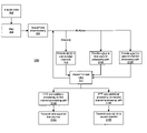
- FIG. 1 is a schematic diagram illustrating an exemplary multiple channel multiple carrier-based system for transmitting data using diversity or multiplexing on a per-tone basis in accordance with at least one embodiment of the present invention.
- FIG. 2 is a schematic diagram illustrating an exemplary multiple channel multiple carrier-based transmitter for transmitting data using diversity or multiplexing on a per-tone basis in accordance with at least one embodiment of the present invention.
- FIG. 3 is a flow diagram illustrating an exemplary operation of the transmitter of FIG. 2 in accordance with at least one embodiment of the present invention.
- FIG. 4 is a schematic diagram illustrating an exemplary multiple channel multiple carrier-based receiver for receiving data using either diversity or multiplexing on a per-tone basis in accordance with at least one embodiment of the present invention.
- FIG. 5 is a flow diagram illustrating an exemplary operation of the receiver of FIG. 4 in accordance with at least one embodiment of the present invention.
- FIGS. 1-5 illustrate various exemplary mechanisms for processing and transmitting data in multiple-channel, multiple carrier systems.
- a transmitter may be connected to a receiver by two or more bonded channels, where the bonded channels may include a physically isolated medium, such as twisted pair lines or coaxial cable, or wireless “virtual” channels, or a combination thereof.
- the frequency transmission bandwidths of each of the bonded channels may be segmented into frequency sub-bands, or “tones,” and each tone then may be used to transmit a symbol stream in parallel with symbol streams on the other tones using any of a variety of multiple carrier transmission techniques, such as DMT or OFDM.
- some or all tones may be examined for the presence of significant signal impairments. If the signal impairments for a given tone are sufficiently low under the surrounding conditions, a multiplexing technique may be implemented for the given tone whereby a different symbol stream is transmitted over the given tone for each bonded channel. This parallel transmission of different symbol streams for the given tone then may be demultiplexed at the receiver. In contrast, if the signal impairments for a given tone have a substantial potential to corrupt any symbol transmitted thereon, a diversity technique may be implemented for the given tone whereby the same symbol stream is transmitted over the given tone for each bonded channel. A spatial diversity technique preferably is used to impute redundancy to the symbol stream transmitted over diversity-mode tones, thereby allowing the receiver to accurately reconstruct the transmitted symbol stream even in the presence of significant interference.
- the various exemplary systems and techniques of the present invention are described in the context of a DMT-based system having two bonded channels. Those skilled in the art, however, may adapt the exemplary systems and techniques to multiple carrier systems having more than two bonded channels (e.g., a DMT-based system having three bonded channels) or to data transmission systems utilizing techniques similar to DMT, such as wireless systems using OFDM, wavelet transform, or other unitary basis approaches, without departing from the spirit or the scope of the present invention.
- the system 100 includes a data source 102 having a transmitter 106 and a data destination 104 having a receiver 108 .
- the data source 102 and the data destination 104 may be interconnected for data transmission purposes by two or more channels 110 A, 110 B.
- the data source 102 may include any of a variety of devices adapted to transmit data over two or more channels using multiple carrier data transmission techniques.
- the data destination 104 may include any of a variety of devices adapted to receive data transmitted in such a manner.
- the data source 102 may include, for example, a DSL access multiplexer (DSLAM) and the data destination 104 may include, for example, a DSL customer premise equipment (CPE) (also known as a DSL modem) wherein data is communicated between the DSLAM and DSL CPE using any of a variety of multiple-channel, multiple-carrier techniques, such as, for example, DMT or OFDM.
- DMT-based DSL systems the physical structure of two or more channels 110 A, 110 B may include, for example, twisted pair lines or coaxial cables.
- one or more of the channels 110 A, 110 B may include a “virtual” channel as wireless channels typically cannot be separated into physically distinct channels but instead often rely on multiple-path propagation features.
- the transmission of data typically is bidirectional. It will be appreciated, therefore, that the data source 102 also may be a data destination for data transmitted from the data destination 104 or another device and that the data destination 104 may be a data source for the data source 102 or another device. Accordingly, the data source 102 and the data destination each may include both the transmitter 106 and the receiver 108 (commonly referred to collectively as a transceiver).
- the transmitter 106 is adapted to transmit data over the channels 110 A, 110 B to the receiver 108 using a DMT-based technique that incorporates both the benefits of diversity and multiplexing.
- This DMT-based technique is herein referred to as Twin DMT or TWDMT.
- Twin DMT twin DMT
- multiplex techniques for bonded channels often may improve the data transmission rate as two different symbol streams may be transmitted over two separate channels, thereby nearly doubling the overall transmission rate.
- Multiplexing is susceptible to signal impairments that often limit the effective reach of multiplex-based transmission techniques.
- diversity techniques over bonded channels increase the reach as the same symbol stream is transmitted over the bonded channels, thereby allowing the receiver to more accurately deduce the actual symbol stream.
- the transmitter 106 is adapted to implement diversity techniques for those tones of the transmission spectrum that are subject to considerable signal impairments while multiplexing techniques may be used for those tones that have relatively little signal impairment.
- the rate benefits of multiplexing and the reach benefits of diversity may be implemented on a per-tone basis to achieve the optimal balance between transmission rate and transmission reach.
- FIG. 1 depicts exemplary transmission frequency spectrum portions 120 A and 120 B for channels 110 A, 110 B, respectively.
- the spectrum portion 120 A includes tones 122 A- 134 A and the spectrum portion 120 B includes tones 122 B- 134 B, where tone 122 A is bonded to tone 122 B, tone 124 A is bonded to tone 124 B, and so one.
- Bonded tones are herein referred to as “twin tones.”
- a tone of channel 110 A is bonded, or the “twin,” of the same tone of channel 110 B (i.e., twin tones have the same frequency sub-band).
- twin tones have the same frequency sub-band.
- the transmitter 106 may be adapted to implement one or more diversity techniques for data transmitted through the twin tones 122 A- 122 B, 124 A- 124 B, 128 A- 128 B and 134 A- 134 B and implement one or more multiplexing techniques for data transmitted through the twin tones 126 A- 126 B, 130 A- 130 B and 132 A- 132 B.
- the receiver 108 may be adapted to receive the signals transmitted over the channels 110 A, 110 B and convert the signals into data for use by the data destination 104 or some other device downstream.
- the transmitter 106 and receiver 108 are discussed in greater detail with reference to FIGS. 3-6 .
- multiplexing techniques typically are suitable when signal impairments, if any, are relatively insignificant whereas diversity techniques are intended to overcome relatively significant signal impairments. Accordingly, any of a variety of methods may be implemented to determine whether a multiplexing technique or a diversity technique is most suitable for a given twin tone.
- one or more criteria for a given tone are measured and compared, individually or in combination, with one or more identified thresholds to determine if substantial signal impairment exists for the given tone. Examples of such criteria may include indicators of signal impairments such as the signal-to-noise ratio (SNR) present for the given tone, the cross-correlation of the noise for the given tone or other quality-of-service (QoS) indicators.
- SNR signal-to-noise ratio
- QoS quality-of-service
- various attributes of the system 100 may be considered.
- various parameters of the system 100 may be considered when determining the minimum threshold SNR for which multiplexing may be used, such as, for example, the distance between the transmitter 106 and the receiver 108 , the symbol rate, the type of encoding used, the presence of known bridge taps, and the like.
- the particular threshold used may depend on the type of modulation and the QoS.
- a minimum SNR of 14.5 dB typically is required to insure a bit error rate (BER) of 10 ⁇ 7 error bits/s in ADSL using 2-bit quadrature amplitude modulation (QAM). Accordingly, it may prove beneficial to employ a SNR of 14.5 dB as the threshold in such a system.
- BER bit error rate
- QAM 2-bit quadrature amplitude modulation
- the identification of tones suitable for either multiplex mode or diversity mode may occur during the training phase of the transmitter and receiver.
- the transmitter 106 could transmit a known sequence of symbols to the receiver 108 .
- the receiver 108 then could compare the actual received symbol sequence with the expected symbol sequence to determine those tones that may be unsuitable for multiplex mode.
- This training phase may be repeated periodically during operation to identify any changes in the transmission environment.
- Other methods for identifying those tones suitable for multiplexing or for diversity may be implemented without departing from the spirit or the scope of the present invention.
- the transmitter 106 includes an encoder 202 and a mapping module 204 .
- the transmitter may further include an inverse fast Fourier transform (IFFT) module 206 A/ 206 B, a parallel-to-serial (P/S) converter 208 A/ 208 B, one or more filters 210 A/ 210 B, a digital-to-analog (D/A) converter 212 A/ 212 B, a low pass filter 214 A/ 214 B, an analog front end (AFe) 216 A/ 216 B, and a hybrid interface 218 A/ 218 B connected to the transmission medium of a respective channels 110 A, 110 B.
- IFFT inverse fast Fourier transform
- P/S parallel-to-serial
- filters 210 A/ 210 B filters
- D/A converter 212 A/ 212 B digital-to-analog converter
- D/A digital-to-analog converter 212 A/ 212 B
- low pass filter 214 A/ 214 B an analog front end (AFe) 216 A/ 216 B
- AFe analog front end
- the components of the transmitter 106 may be implemented as software, hardware, firmware, or a combination thereof.
- the encoder 202 , mapping module 204 , IFFT 206 A/ 206 B, P/S converter 208 A/ 208 B and/or filter 210 A/ 210 B may be implemented as one or more sets of executable instructions adapted to manipulate one or more processors to perform their functions described below.
- the one or more processors may include a microprocessor or central processing unit (CPU), an application specific integrated circuit (ASIC), a digital signal processor (DSP) and the like.
- the D/A converter 212 A/ 212 B, low pass filter 214 A/ 214 B, analog front end 216 A/ 216 B and hybrid 218 A/ 218 B typically are implemented as hardware components.
- the transmitter 106 may further include a master clock 224 whose time signal may be provided to and used by one or more of the other components of the transmitter 106 .
- the time signal of the master clock 224 may be transmitted over one or both of channels 110 A, 110 B to the receiver 108 in order to synchronize the clock of the receiver 108 to the master clock 224 using any of a variety of clock-synchronization techniques (e.g., the use of a phase locked loop (PLL)).
- PLL phase locked loop
- data to be transmitted may be supplied as a bitstream to the encoder 202 whereupon the bitstream may be encoded to include redundant bits. This redundancy typically provides robustness to the resulting transmitted signal and allows the receiver to more accurately reconstruct the transmitted bitstream.
- the encoder 202 may include a multilevel encoder that employs one or a combination of the following: space-based encoding, time-based encoding, interleaving, trellis coded modulation (TCM), Reed Solomon coding, and the like.
- mapping module 204 may provide one or more mapping functions (also known as modulation functions) at step 304 whereupon one or more mapping functions (also known as modulation functions) may be applied to the bitstream.
- mapping functions also known as modulation functions
- Examples of mapping functions that may be beneficially used may include quadrature amplitude modulation (QAM), phase shift keying (PSK), amplitude shift keying (ASK), binary phase shift keying (BPSK), frequency shift keying (FSK), and the like.
- space/time pre-processing may be performed on the output at step 306 .
- This pre-processing may include introducing channel information into the symbols to be transmitted to compensate for interference between the two or more channels, thereby rendering the channels orthogonal.
- the frequency response of the channels that comprise the main path and the cross path might be identified during training on a per-bin basis.
- the resulting complex coefficients may be combined with the complex value that is intended to be transmitted on the channels.
- mapping function(s) to the bitstream typically results in the generation of complex values, each representing a symbol to be transmitted over a respective tone of the corresponding channel.
- those twin tones that support multiplexing are denoted herein as q and those twin tones that support diversity are denoted herein as q′.
- the complex value representing a symbol to be transmitted over the bonded tone q′ of the first channel in diversity mode is herein denoted as a 1 [q′,t] for time symbol t.
- the complex value representing a symbol to be transmitted over the twin tone q′ of the second channel in diversity mode is herein denoted as a 2 [q′,t].
- the complex value representing a symbol transmitted over the bonded tone q of the first channel in multiplexing mode is denoted herein as a 1 [q,t] for time symbol t
- the complex value representing a symbol transmitted over the second channel in multiplexing mode is denoted as a 2 [q,t]
- different symbol streams may be transmitted over each channel for twin tones operating in multiplex mode.
- the relationship between complex values transmitted in multiplex mode therefore may be understood as: a 1 [q,t] ⁇ a 2 [q,t] EQ. 2
- the complex value(s) generated for some or all of the tones of the frequency spectrum of the bonded channels may be distributed to one of the respective channel processing paths 220 A, 220 B.
- the complex value a[q′,t] may be provided at step 308 to both the first channel processing path 220 A and the second channel processing path 220 B for processing and transmission over both channels 110 A, 110 B in parallel.
- the complex value a 1 [q,t] may be provided to the first channel processing path 220 A for processing and transmission over channel 110 A at step 310 A and the complex value a 2 [q,t] may be provided to the second channel processing path 220 B for processing and transmission over channel 110 B at step 310 B.
- Steps 308 , 310 A and 310 B may be repeated at step 312 for some or all of the twin tones of the frequency spectrum of the bonded channels 110 A, 110 B according to the operating mode (i.e., diversity or multiplexing) of the respective twin tones.
- the output of the mapping module 204 is processed and prepared by the channel processing paths 220 A/ 220 B for transmittal over the physical medium of the channels 110 A/ 110 B, respectively.
- the channel processing paths 220 A, 220 B may implement techniques commonly found in DMT-based transmitters, OFDM-based transmitters and other multiple carrier-based transmission systems. Generally, this processing may include: conversion from the frequency domain to the time domain by the IFFT modules 206 A/ 206 B using, for example, an IFFT or similar process.
- the output of the IFFT modules 206 A/ 206 B then may undergo a parallel-to-serial conversion by the P/S modules 208 A/ 208 B, shape filtering or other types of filtering by the filters 210 A/ 210 B.
- the resulting data then may be converted from the digital domain to the analog domain for transmission by the D/A converters 212 A/ 212 B and then filtered by the low pass filters 214 A/ 214 B.
- the resulting analog signals then may be provided to the analog front ends 216 A/ 216 B at steps 316 A, 316 B for transmission via hybrid interface 218 A/ 218 B to the receiver 108 over the channel 110 A, 110 B, respectively.
- the receiver 108 includes channel processing paths 430 A, 430 B for channels 110 A, 110 B, respectively.
- the channel processing path 430 A may include a hybrid interface 402 A, an analog front end 404 A, a low pass filter 406 A, an analog-to-digital (A/D) converter 408 A, a shaping filter 410 A, a time-domain equalizer 412 A, a serial-to-parallel (S/P) converter 414 A, and a fast Fourier transform (FFT) module 416 A.
- the channel processing path 430 B may include a hybrid interface 402 B, an analog front end 404 B, a low pass filter 406 B, an analog-to-digital (A/D) converter 408 B, a shaping filter 4101 B, a time-domain equalizer 412 B, S/P converter 414 B, and a FFT module 416 B.
- A/D analog-to-digital
- the receiver 108 further may include a vector frequency equalizer (FEQ) 418 A for processing diversity-mode tones and a matrix FEQ 418 B for processing multiplex-mode based tones.
- the receiver 108 also may include an inverse mapping module 420 and decoder 422 to inverse map and decode the output of the FEQs 418 A, 418 B to generate a bitstream that represents the bitstream provided to the encoder 202 of the transmitter 106 ( FIG. 2 ).
- the components of the receiver 108 may be implemented as software, hardware, firmware, or a combination thereof.
- the hybrid interface 402 A/ 402 B, the analog front end 404 A/ 404 B, low pass filter 406 A/ 406 B and A/D converter 408 A/ 408 B typically are implemented as hardware components whereas the filter 410 A/ 410 B, TEQ 412 A/ 412 B, S/P converter 414 A/ 414 B, FFT 416 A/ 416 B, vector FEQ 418 A, matrix FEQ 418 B, inverse mapping module 420 and decoder 422 typically are implemented as one or more sets of executable instructions adapted to manipulate one or more processors to perform the functions described below. It should be understood that alternative configurations of hardware and software may be implemented as contemplated by the present invention.
- the receiver 108 additionally may include a master clock 424 to synchronize some or all of the receiver components so that the incoming symbol stream of each channel may be processed in parallel with the symbol stream of the other channel. Further, the master clock 424 may be synchronized with the master clock 224 of the transmitter 106 ( FIG. 2 ) using a PLL or other suitable technique.
- the signal received over the first channel may be preprocessed by the channel processing path 430 A to convert the transmitted signal from the time-domain to the frequency domain, to improve the signal characteristics, and the like.
- the signal received over the second channel may be similarly preprocessed by the channel processing path 430 B.
- the channel processing paths 430 A, 430 B may implement techniques commonly found in DMT-based receivers, OFDM-based receivers and other multiple carrier-based reception systems. This preprocessing may be viewed as the inverse or complement of the processing provided by the channel processing paths 220 A, 220 B ( FIG. 2 ) and typically may include: processing by hybrid module 402 A/ 402 B to reduce or remove undesirable effects of the simultaneous transmission and reception of signals over the same channel; processing by the analog front end 404 A/ 404 B (analogous to the analog front end 216 A/ 216 B of FIG. 2 ); low pass filtering by low pass filter 406 A/ 406 B; analog-to-digital conversion by A/D converter 408 A/ 408 B; and shape filtering by filter 410 A/ 410 B.
- the output of the filters 410 A/ 410 B then may be processed by a time-domain equalizer (TEQ) 412 A/ 412 B. While FIG. 4 illustrates the processing of each channel by a separate TEQ, it will be appreciated that the channels 110 A, 110 B may be cross-coupled and it therefore may be advantageous to process both channels by the same TEQ to use the information in one channel to reduce the interference it caused the other channel.
- the output of the TEQs 412 A/ 412 B then may undergo a serial-to-parallel conversion by the S/P module 414 A/ 414 B.
- the serialized output then may be converted from the time domain to the frequency domain by the FFT module 416 A/ 416 B using an FFT process or similar process.
- the resulting processed signal for each channel then may be supplied to both the vector FEQ 418 A and the matrix FEQ 418 B.
- a symbol transmitted in parallel over bonded channels operating in diversity mode typically experiences a complex gain h i [q′] and complex disturbances w i [q′,t] for channel i of the two or more bonded channels, where the complex disturbances may be correlated as a result of cross talk between the channels, as illustrated by EQs. 3 and 4:
- the received signals may be processed by the vector FEQ 418 A using a vector FEQ function g[q′,t] to derive an estimate, denoted â[q′,t], of the complex value a[q′,t] originally transmitted.
- An appropriate vector FEQ function g[q′,t] may be determined using any of a variety of techniques, such as, for example, a least-mean-squared approach or a maximum-likelihood approach.
- the vector FEQ function g[q′,t] preferably is derived during training and/or periodically during operation and is selected so that the difference between the estimate â[q′,t] and the transmitted complex value a[q′,t] is minimized.
- a symbol transmitted over a channel operating in multiplex mode typically experiences a direct path complex gain h ii [q] and complex disturbances w i [q′,t] for channel i.
- the multiplex-mode tones q of the received signals may be processed by the matrix FEQ 418 B using a matrix FEQ function G[q,t] to derive an estimate, denoted â i [q,t], of the complex value a i [q,t] originally transmitted over channel i.
- G[q,t] may be determined using any of a variety of techniques, such as, for example, a least-mean-squared approach or a maximum-likelihood approach.
- an appropriate matrix FEQ function G[q,t] may be determined using any of a variety of techniques, such as, for example, a least-mean-squared approach or a maximum-likelihood approach.
- the matrix FEQ function G[q,t] preferably is derived during training and/or periodically during operation and is selected so that the difference between the estimate â i [q,t] and the transmitted complex value a i [q,t] is minimized.
- the process represented by EQ. 11 typically reduces or eliminates FEXT resulting from the bonded channels. NEXT, however, may be mitigated through cooperation between the transmitters and receivers located on the same side.
- the estimated complex values then may be submitted to the inverse mapping module 420 and decoder 422 for inverse mapping (step 506 ) and decoding (step 508 ) to generate a bitstream representative of the bitstream supplied to the encoder 202 of the transmitter 106 ( FIG. 1 ).
- the inverse mapping process implemented by the inverse mapping module 420 preferably is compatible with the mapping process implemented by the mapping module 204 of the transmitter 106 .
- the decoding process implemented by the decoder 422 preferably is compatible with the encoding process implemented by the encoder 202 .
- the resulting bitstream may be further processed as appropriate for use by the data destination 104 ( FIG. 1 ) or other device.
- the technique for improving reach and rate of multiple-channel multi-tone transmissions in accordance with the present disclosure as described above typically involves the processing of input data and the generation of output data to some extent.
- This input data processing and output data generation may be implemented in hardware or software.
- specific electronic components may be employed in a computer and/or communications network or similar or related circuitry for implementing the functions associated with multiple-channel multi-tone transmissions in accordance with the present disclosure as described above.
- one or more processors operating in accordance with stored instructions may implement the functions associated with multiple-channel multi-tone transmissions in accordance with the present disclosure as described above. If such is the case, it is within the scope of the present disclosure that such instructions may be stored on one or more processor readable carriers (e.g., a magnetic disk), or transmitted to one or more processors via one or more signals.
- processor readable carriers e.g., a magnetic disk
Abstract
Description
a 1 [q′,t]=a 2 [q′,t]=a[q′,t] EQ.1
a 1 [q,t]≠a 2 [q,t] EQ. 2
â[q′,t]=x T [q′,t]g[q′,t] EQ. 5
where xT represents the column-to-row transform of x. An appropriate vector FEQ function g[q′,t] may be determined using any of a variety of techniques, such as, for example, a least-mean-squared approach or a maximum-likelihood approach. The vector FEQ function g[q′,t] preferably is derived during training and/or periodically during operation and is selected so that the difference between the estimate â[q′,t] and the transmitted complex value a[q′,t] is minimized.
x i [q,t]=h ii [q]a i [q,t]+h ij [q]a j [q,t]+q i [q,t] EQ. 6
or
x[q,t]=H[q]a[q,t]+w[q,t] EQ. 7
where
â[q,t]=G[q,t]x[q,t] EQ. 11
where G[q,t] may be determined using any of a variety of techniques, such as, for example, a least-mean-squared approach or a maximum-likelihood approach. As with the vector FEQ function g[q′,t], an appropriate matrix FEQ function G[q,t] may be determined using any of a variety of techniques, such as, for example, a least-mean-squared approach or a maximum-likelihood approach. The matrix FEQ function G[q,t] preferably is derived during training and/or periodically during operation and is selected so that the difference between the estimate âi[q,t] and the transmitted complex value ai[q,t] is minimized. The process represented by EQ. 11 typically reduces or eliminates FEXT resulting from the bonded channels. NEXT, however, may be mitigated through cooperation between the transmitters and receivers located on the same side.
Claims (19)
Priority Applications (1)
| Application Number | Priority Date | Filing Date | Title |
|---|---|---|---|
| US10/874,329 US7653138B2 (en) | 2003-06-24 | 2004-06-24 | Technique for improving multiple-channel multi-tone transmissions |
Applications Claiming Priority (2)
| Application Number | Priority Date | Filing Date | Title |
|---|---|---|---|
| US48076903P | 2003-06-24 | 2003-06-24 | |
| US10/874,329 US7653138B2 (en) | 2003-06-24 | 2004-06-24 | Technique for improving multiple-channel multi-tone transmissions |
Publications (2)
| Publication Number | Publication Date |
|---|---|
| US20050013379A1 US20050013379A1 (en) | 2005-01-20 |
| US7653138B2 true US7653138B2 (en) | 2010-01-26 |
Family
ID=33563817
Family Applications (1)
| Application Number | Title | Priority Date | Filing Date |
|---|---|---|---|
| US10/874,329 Expired - Fee Related US7653138B2 (en) | 2003-06-24 | 2004-06-24 | Technique for improving multiple-channel multi-tone transmissions |
Country Status (3)
| Country | Link |
|---|---|
| US (1) | US7653138B2 (en) |
| JP (1) | JP2007525071A (en) |
| WO (1) | WO2005004429A1 (en) |
Cited By (2)
| Publication number | Priority date | Publication date | Assignee | Title |
|---|---|---|---|---|
| US20070263711A1 (en) * | 2006-04-26 | 2007-11-15 | Theodor Kramer Gerhard G | Operating DSL subscriber lines |
| US8488623B2 (en) | 2010-07-28 | 2013-07-16 | Altera Corporation | Scalable interconnect modules with flexible channel bonding |
Families Citing this family (17)
| Publication number | Priority date | Publication date | Assignee | Title |
|---|---|---|---|---|
| US6956872B1 (en) * | 2000-05-22 | 2005-10-18 | Globespanvirata, Inc. | System and method for encoding DSL information streams having differing latencies |
| US7639596B2 (en) * | 2003-12-07 | 2009-12-29 | Adaptive Spectrum And Signal Alignment, Inc. | High speed multiple loop DSL system |
| US7610017B2 (en) | 2005-06-09 | 2009-10-27 | Vixs Systems, Inc. | Increased data rate transmissions of a wireless communication |
| US8027299B2 (en) | 2005-11-25 | 2011-09-27 | Gal Zuckerman | Hybrid system having multiple downlink channels and a single uplink channel |
| US8130629B2 (en) * | 2005-11-25 | 2012-03-06 | Go Net Systems Ltd | Simultaneous simulcast and single cast hybrid multi-tone communication system |
| US20070121743A1 (en) * | 2005-11-25 | 2007-05-31 | Go Networks, Inc. | Ubiquitous coverage OFDM hybrid system |
| US8526359B2 (en) * | 2005-11-25 | 2013-09-03 | Go Net Systems Ltd. | Hybrid point to multipoint communication system |
| US8270336B2 (en) * | 2005-11-25 | 2012-09-18 | Go Net Systems Ltd. | Filtering process for enhancing OFDMA uplink reception sensitivity |
| US7653141B2 (en) * | 2006-03-31 | 2010-01-26 | Panasonic Corporation | Multi-band OFDM UWB communication systems having improved frequency diversity |
| US8270513B2 (en) * | 2006-05-31 | 2012-09-18 | Cobham Defense Electronic Systems Corporation | Fully saturated multi-tone transceiver |
| EP2173041B1 (en) * | 2007-07-23 | 2017-03-01 | Alcatel Lucent | Power controlling method and corresponding base station |
| EP2136520A1 (en) * | 2008-06-20 | 2009-12-23 | Nokia Siemens Networks Oy | Method and device for processing data and communication system comprising such device |
| US20140071994A1 (en) * | 2012-09-09 | 2014-03-13 | Steven Sharp | Method and Systems for Full Duplex Communication Using a Single Channel |
| CN107438987B (en) * | 2015-03-31 | 2020-10-23 | 英国电讯有限公司 | Method and system for transmitting data between transmitter and receiver, and transceiver |
| US11637612B2 (en) | 2015-08-25 | 2023-04-25 | Cellium Technologies, Ltd. | Macro-diversity using hybrid transmissions via twisted pairs |
| US10845401B2 (en) * | 2017-08-30 | 2020-11-24 | Keysight Technologies, Inc. | Nonlinear distortion detection |
| WO2020041926A1 (en) * | 2018-08-27 | 2020-03-05 | 华为技术有限公司 | Communication device, and system and method therefor |
Citations (17)
| Publication number | Priority date | Publication date | Assignee | Title |
|---|---|---|---|---|
| EP1185001A2 (en) | 2000-09-01 | 2002-03-06 | Nortel Networks Limited | Adaptive time deversity and spatial diversity for OFDM |
| US20020051435A1 (en) | 2000-10-27 | 2002-05-02 | L-3 Communications Corporation | Two-dimensional channel bonding in a hybrid CDMA/FDMA fixed wireless access system to provide finely variable rate channels |
| US6456653B1 (en) | 1999-08-25 | 2002-09-24 | Lucent Technologies Inc. | Fast and accurate signal-to-noise ratio estimation technique for OFDM systems |
| US20020181609A1 (en) | 1999-03-12 | 2002-12-05 | Aware, Inc. | Seamless rate adaptive multicarrier modulation system and protocols |
| US20030007509A1 (en) | 1998-06-26 | 2003-01-09 | Aware, Inc. | Multicarrier communication with variable overhead rate |
| US20030035491A1 (en) | 2001-05-11 | 2003-02-20 | Walton Jay R. | Method and apparatus for processing data in a multiple-input multiple-output (MIMO) communication system utilizing channel state information |
| US20030048802A1 (en) | 2001-09-05 | 2003-03-13 | Kishan Shenoi | Bonded G.shdsl links for ATM backhaul applications |
| US20030064690A1 (en) | 2001-09-28 | 2003-04-03 | Kasapi Athanasios A. | System and related methods for introducing sub-carrier diversity in a wideband communication system |
| US20030073464A1 (en) | 2001-05-25 | 2003-04-17 | Giannakis Georgios B. | Space-time coded transmissions within a wireless communication network |
| US20030076890A1 (en) | 2001-07-26 | 2003-04-24 | Lucent Technologies, Inc. | Method and apparatus for detection and decoding of signals received from a linear propagation channel |
| US20030087651A1 (en) | 2001-11-02 | 2003-05-08 | Dennis Rauschmayer | Method of and apparatus for implementing adaptive downstream modulation in a fixed wireless communication system |
| US20030086371A1 (en) | 2001-11-02 | 2003-05-08 | Walton Jay R | Adaptive rate control for OFDM communication system |
| WO2003039031A1 (en) * | 2001-10-31 | 2003-05-08 | Matsushita Electric Industrial Co., Ltd. | Radio transmission apparatus and radio communication method |
| US20030091053A1 (en) | 2001-10-05 | 2003-05-15 | Aware, Inc. | Systems and methods for multi-pair ATM over DSL |
| US20030091133A1 (en) | 2001-10-24 | 2003-05-15 | Redfern Arthur John | Multiple path equalization for multicarrier systems |
| US7095790B2 (en) * | 2003-02-25 | 2006-08-22 | Qualcomm, Incorporated | Transmission schemes for multi-antenna communication systems utilizing multi-carrier modulation |
| US7106760B1 (en) * | 2002-03-29 | 2006-09-12 | Centillium Communications, Inc. | Channel bonding in SHDSL systems |
-
2004
- 2004-06-24 US US10/874,329 patent/US7653138B2/en not_active Expired - Fee Related
- 2004-06-24 WO PCT/US2004/020015 patent/WO2005004429A1/en active Application Filing
- 2004-06-24 JP JP2006517548A patent/JP2007525071A/en active Pending
Patent Citations (19)
| Publication number | Priority date | Publication date | Assignee | Title |
|---|---|---|---|---|
| US20030007509A1 (en) | 1998-06-26 | 2003-01-09 | Aware, Inc. | Multicarrier communication with variable overhead rate |
| US20020181609A1 (en) | 1999-03-12 | 2002-12-05 | Aware, Inc. | Seamless rate adaptive multicarrier modulation system and protocols |
| US6456653B1 (en) | 1999-08-25 | 2002-09-24 | Lucent Technologies Inc. | Fast and accurate signal-to-noise ratio estimation technique for OFDM systems |
| EP1185001A2 (en) | 2000-09-01 | 2002-03-06 | Nortel Networks Limited | Adaptive time deversity and spatial diversity for OFDM |
| US20020051435A1 (en) | 2000-10-27 | 2002-05-02 | L-3 Communications Corporation | Two-dimensional channel bonding in a hybrid CDMA/FDMA fixed wireless access system to provide finely variable rate channels |
| US20030035491A1 (en) | 2001-05-11 | 2003-02-20 | Walton Jay R. | Method and apparatus for processing data in a multiple-input multiple-output (MIMO) communication system utilizing channel state information |
| US20030073464A1 (en) | 2001-05-25 | 2003-04-17 | Giannakis Georgios B. | Space-time coded transmissions within a wireless communication network |
| US20030076890A1 (en) | 2001-07-26 | 2003-04-24 | Lucent Technologies, Inc. | Method and apparatus for detection and decoding of signals received from a linear propagation channel |
| US20030048802A1 (en) | 2001-09-05 | 2003-03-13 | Kishan Shenoi | Bonded G.shdsl links for ATM backhaul applications |
| US20030064690A1 (en) | 2001-09-28 | 2003-04-03 | Kasapi Athanasios A. | System and related methods for introducing sub-carrier diversity in a wideband communication system |
| US20030091053A1 (en) | 2001-10-05 | 2003-05-15 | Aware, Inc. | Systems and methods for multi-pair ATM over DSL |
| US20030091133A1 (en) | 2001-10-24 | 2003-05-15 | Redfern Arthur John | Multiple path equalization for multicarrier systems |
| WO2003039031A1 (en) * | 2001-10-31 | 2003-05-08 | Matsushita Electric Industrial Co., Ltd. | Radio transmission apparatus and radio communication method |
| EP1363410A1 (en) * | 2001-10-31 | 2003-11-19 | Matsushita Electric Industrial Co., Ltd. | Radio transmission apparatus and radio communication method |
| US20040087282A1 (en) | 2001-10-31 | 2004-05-06 | Kimihiko Ishikawa | Radio transmission apparatus and radio communication method |
| US20030087651A1 (en) | 2001-11-02 | 2003-05-08 | Dennis Rauschmayer | Method of and apparatus for implementing adaptive downstream modulation in a fixed wireless communication system |
| US20030086371A1 (en) | 2001-11-02 | 2003-05-08 | Walton Jay R | Adaptive rate control for OFDM communication system |
| US7106760B1 (en) * | 2002-03-29 | 2006-09-12 | Centillium Communications, Inc. | Channel bonding in SHDSL systems |
| US7095790B2 (en) * | 2003-02-25 | 2006-08-22 | Qualcomm, Incorporated | Transmission schemes for multi-antenna communication systems utilizing multi-carrier modulation |
Non-Patent Citations (2)
| Title |
|---|
| Gesbert, D.; Shafi, M.; Da-shan Shiu; Smith, P.J.; Naguib, A.;"From theory to practice: an overview of MIMO space-time coded wireless systems," IEEE Journal on Selected Areas in Communications, vol. 21, Issue: 3 , Apr. 2003, pp. 281-302. |
| Ginis, G.; Cioffi, J.M.;"Vectored transmission for digital subscriber line systems," IEEE Journal on Selected Areas in Communications, ,vol. 20 , Issue: 5 , Jun. 2002, pp. 1085-1104. |
Cited By (2)
| Publication number | Priority date | Publication date | Assignee | Title |
|---|---|---|---|---|
| US20070263711A1 (en) * | 2006-04-26 | 2007-11-15 | Theodor Kramer Gerhard G | Operating DSL subscriber lines |
| US8488623B2 (en) | 2010-07-28 | 2013-07-16 | Altera Corporation | Scalable interconnect modules with flexible channel bonding |
Also Published As
| Publication number | Publication date |
|---|---|
| WO2005004429A1 (en) | 2005-01-13 |
| JP2007525071A (en) | 2007-08-30 |
| US20050013379A1 (en) | 2005-01-20 |
Similar Documents
| Publication | Publication Date | Title |
|---|---|---|
| US7653138B2 (en) | Technique for improving multiple-channel multi-tone transmissions | |
| US7352805B2 (en) | Systems and methods for adaptive VDSL with variable sampling frequency and time-domain equalizer | |
| US8391383B2 (en) | Dynamic tone grouping and encoding for multi-carrier quadrature amplitude in OFDM | |
| JP3679722B2 (en) | Enhanced bit loading for multi-carrier communication channels | |
| EP2043274B1 (en) | Transmission method together with multi pairs of lines, sender and receiver thereof | |
| US6628722B1 (en) | Decoding technique in discrete multi-tone (DMT) based communications systems | |
| US6353629B1 (en) | Poly-path time domain equalization | |
| JP3692044B2 (en) | Equalizer training for ADSL transceivers in TCM-ISDN crosstalk environment | |
| US7403569B2 (en) | Efficient low-power mode for multicarrier communications | |
| CN1708037B (en) | Method for the reception of data signal, corresponding reception device | |
| US6201830B1 (en) | Low computation idle transmission method for DSL modems | |
| JPH09505185A (en) | High-speed digital subscriber line discrete multi-tone transmission | |
| US20180083815A1 (en) | Method and apparatus for transmitting and receiving signals over two pairs of wires | |
| US7027537B1 (en) | Iterative multi-user detection | |
| Emre et al. | Multiinput multioutput OFDM for shallow-water UWA communications | |
| US20050063479A1 (en) | Communication data using wideband communications | |
| US7564868B2 (en) | Configuration DSL transceiver | |
| CA2254807C (en) | Method and system for synchronizing time-division-duplexed transceivers | |
| US7236532B2 (en) | Method of initializing a communication system with different bandwidth receivers and transmitters | |
| CA2387814A1 (en) | Bit allocation method and apparatus for improving transmission bit rate in a multicarrier system | |
| CN113411281B (en) | F-OFDM wireless transmission method based on parallel interference elimination | |
| CN113746773A (en) | Multi-carrier communication system and method based on frequency domain diversity |
Legal Events
| Date | Code | Title | Description |
|---|---|---|---|
| AS | Assignment |
Owner name: GLOBESPAN VIRATA INCORPORATED, NEW JERSEY Free format text: ASSIGNMENT OF ASSIGNORS INTEREST;ASSIGNORS:DUVAUT, PATRICK;LANGBERG, EHUD;SCHOLTZ, WILLIAM;REEL/FRAME:015847/0507;SIGNING DATES FROM 20040922 TO 20040927 |
|
| AS | Assignment |
Owner name: CONEXANT, INC.,NEW JERSEY Free format text: CHANGE OF NAME;ASSIGNOR:GLOBESPANVIRATA, INC.;REEL/FRAME:018471/0286 Effective date: 20040528 Owner name: CONEXANT, INC., NEW JERSEY Free format text: CHANGE OF NAME;ASSIGNOR:GLOBESPANVIRATA, INC.;REEL/FRAME:018471/0286 Effective date: 20040528 |
|
| AS | Assignment |
Owner name: THE BANK OF NEW YORK TRUST COMPANY, N.A., AS COLLA Free format text: SECURITY AGREEMENT;ASSIGNOR:BROOKTREE BROADBAND HOLDING, INC.;REEL/FRAME:018860/0690 Effective date: 20061113 |
|
| AS | Assignment |
Owner name: BROOKTREE BROADBAND HOLDING, INC.,CALIFORNIA Free format text: ASSIGNMENT OF ASSIGNORS INTEREST;ASSIGNOR:GLOBESPANVIRATA, INC.;REEL/FRAME:018861/0132 Effective date: 20040228 Owner name: BROOKTREE BROADBAND HOLDING, INC., CALIFORNIA Free format text: ASSIGNMENT OF ASSIGNORS INTEREST;ASSIGNOR:GLOBESPANVIRATA, INC.;REEL/FRAME:018861/0132 Effective date: 20040228 |
|
| AS | Assignment |
Owner name: BROOKTREE BROADBAND HOLDING, INC, CALIFORNIA Free format text: RELEASE BY SECURED PARTY;ASSIGNOR:THE BANK OF NEW YORK MELLON TRUST COMPANY, N.A.;REEL/FRAME:023148/0566 Effective date: 20090821 Owner name: BROOKTREE BROADBAND HOLDING, INC,CALIFORNIA Free format text: RELEASE BY SECURED PARTY;ASSIGNOR:THE BANK OF NEW YORK MELLON TRUST COMPANY, N.A.;REEL/FRAME:023148/0566 Effective date: 20090821 |
|
| AS | Assignment |
Owner name: IKANOS COMMUNICATIONS, INC., CALIFORNIA Free format text: ASSIGNMENT OF ASSIGNORS INTEREST;ASSIGNORS:CONEXANT SYSTEMS, INC.;CONEXANT, INC.;BROOKTREE BROADBAND HOLDING INC.;REEL/FRAME:023163/0723 Effective date: 20090824 Owner name: IKANOS COMMUNICATIONS, INC.,CALIFORNIA Free format text: ASSIGNMENT OF ASSIGNORS INTEREST;ASSIGNORS:CONEXANT SYSTEMS, INC.;CONEXANT, INC.;BROOKTREE BROADBAND HOLDING INC.;REEL/FRAME:023163/0723 Effective date: 20090824 |
|
| CC | Certificate of correction | ||
| FPAY | Fee payment |
Year of fee payment: 4 |
|
| AS | Assignment |
Owner name: ALCATEL-LUCENT USA, INC., NEW JERSEY Free format text: NOTICE OF GRANT OF SECURITY INTEREST IN PATENTS;ASSIGNOR:IKANOS COMMUNICATIONS, INC.;REEL/FRAME:035581/0710 Effective date: 20150430 |
|
| AS | Assignment |
Owner name: SILICON VALLEY BANK, CALIFORNIA Free format text: SECURITY INTEREST;ASSIGNOR:IKANOS COMMUNICATIONS, INC.;REEL/FRAME:035874/0351 Effective date: 20150602 |
|
| AS | Assignment |
Owner name: IKANOS COMMUNICATIONS, INC., CALIFORNIA Free format text: RELEASE BY SECURED PARTY;ASSIGNOR:SILICON VALLEY BANK;REEL/FRAME:036733/0031 Effective date: 20150930 Owner name: IKANOS COMMUNICATIONS, INC., CALIFORNIA Free format text: RELEASE BY SECURED PARTY;ASSIGNOR:ALCATEL-LUCENT USA, INC.;REEL/FRAME:036732/0876 Effective date: 20150929 |
|
| FEPP | Fee payment procedure |
Free format text: PAYOR NUMBER ASSIGNED (ORIGINAL EVENT CODE: ASPN); ENTITY STATUS OF PATENT OWNER: LARGE ENTITY |
|
| FEPP | Fee payment procedure |
Free format text: MAINTENANCE FEE REMINDER MAILED (ORIGINAL EVENT CODE: REM.) |
|
| LAPS | Lapse for failure to pay maintenance fees |
Free format text: PATENT EXPIRED FOR FAILURE TO PAY MAINTENANCE FEES (ORIGINAL EVENT CODE: EXP.) |
|
| STCH | Information on status: patent discontinuation |
Free format text: PATENT EXPIRED DUE TO NONPAYMENT OF MAINTENANCE FEES UNDER 37 CFR 1.362 |
|
| FP | Lapsed due to failure to pay maintenance fee |
Effective date: 20180126 |