US7640962B2 - Multiple tape application method and apparatus - Google Patents
Multiple tape application method and apparatus Download PDFInfo
- Publication number
- US7640962B2 US7640962B2 US11/110,437 US11043705A US7640962B2 US 7640962 B2 US7640962 B2 US 7640962B2 US 11043705 A US11043705 A US 11043705A US 7640962 B2 US7640962 B2 US 7640962B2
- Authority
- US
- United States
- Prior art keywords
- web
- anvil roll
- adhesive
- tape
- protrusion
- Prior art date
- Legal status (The legal status is an assumption and is not a legal conclusion. Google has not performed a legal analysis and makes no representation as to the accuracy of the status listed.)
- Active, expires
Links
Images


Classifications
-
- B—PERFORMING OPERATIONS; TRANSPORTING
- B65—CONVEYING; PACKING; STORING; HANDLING THIN OR FILAMENTARY MATERIAL
- B65H—HANDLING THIN OR FILAMENTARY MATERIAL, e.g. SHEETS, WEBS, CABLES
- B65H39/00—Associating, collating, or gathering articles or webs
- B65H39/14—Associating sheets with webs
-
- B—PERFORMING OPERATIONS; TRANSPORTING
- B65—CONVEYING; PACKING; STORING; HANDLING THIN OR FILAMENTARY MATERIAL
- B65H—HANDLING THIN OR FILAMENTARY MATERIAL, e.g. SHEETS, WEBS, CABLES
- B65H2301/00—Handling processes for sheets or webs
- B65H2301/10—Selective handling processes
- B65H2301/12—Selective handling processes of sheets or web
- B65H2301/121—Selective handling processes of sheets or web for sheet handling processes, i.e. wherein the web is cut into sheets
-
- B—PERFORMING OPERATIONS; TRANSPORTING
- B65—CONVEYING; PACKING; STORING; HANDLING THIN OR FILAMENTARY MATERIAL
- B65H—HANDLING THIN OR FILAMENTARY MATERIAL, e.g. SHEETS, WEBS, CABLES
- B65H2801/00—Application field
- B65H2801/57—Diaper manufacture
-
- Y—GENERAL TAGGING OF NEW TECHNOLOGICAL DEVELOPMENTS; GENERAL TAGGING OF CROSS-SECTIONAL TECHNOLOGIES SPANNING OVER SEVERAL SECTIONS OF THE IPC; TECHNICAL SUBJECTS COVERED BY FORMER USPC CROSS-REFERENCE ART COLLECTIONS [XRACs] AND DIGESTS
- Y10—TECHNICAL SUBJECTS COVERED BY FORMER USPC
- Y10T—TECHNICAL SUBJECTS COVERED BY FORMER US CLASSIFICATION
- Y10T156/00—Adhesive bonding and miscellaneous chemical manufacture
- Y10T156/10—Methods of surface bonding and/or assembly therefor
- Y10T156/1052—Methods of surface bonding and/or assembly therefor with cutting, punching, tearing or severing
- Y10T156/1084—Methods of surface bonding and/or assembly therefor with cutting, punching, tearing or severing of continuous or running length bonded web
-
- Y—GENERAL TAGGING OF NEW TECHNOLOGICAL DEVELOPMENTS; GENERAL TAGGING OF CROSS-SECTIONAL TECHNOLOGIES SPANNING OVER SEVERAL SECTIONS OF THE IPC; TECHNICAL SUBJECTS COVERED BY FORMER USPC CROSS-REFERENCE ART COLLECTIONS [XRACs] AND DIGESTS
- Y10—TECHNICAL SUBJECTS COVERED BY FORMER USPC
- Y10T—TECHNICAL SUBJECTS COVERED BY FORMER US CLASSIFICATION
- Y10T156/00—Adhesive bonding and miscellaneous chemical manufacture
- Y10T156/12—Surface bonding means and/or assembly means with cutting, punching, piercing, severing or tearing
- Y10T156/1317—Means feeding plural workpieces to be joined
- Y10T156/1322—Severing before bonding or assembling of parts
- Y10T156/133—Delivering cut part to indefinite or running length web
-
- Y—GENERAL TAGGING OF NEW TECHNOLOGICAL DEVELOPMENTS; GENERAL TAGGING OF CROSS-SECTIONAL TECHNOLOGIES SPANNING OVER SEVERAL SECTIONS OF THE IPC; TECHNICAL SUBJECTS COVERED BY FORMER USPC CROSS-REFERENCE ART COLLECTIONS [XRACs] AND DIGESTS
- Y10—TECHNICAL SUBJECTS COVERED BY FORMER USPC
- Y10T—TECHNICAL SUBJECTS COVERED BY FORMER US CLASSIFICATION
- Y10T156/00—Adhesive bonding and miscellaneous chemical manufacture
- Y10T156/12—Surface bonding means and/or assembly means with cutting, punching, piercing, severing or tearing
- Y10T156/1317—Means feeding plural workpieces to be joined
- Y10T156/1322—Severing before bonding or assembling of parts
- Y10T156/1339—Delivering cut part in sequence to serially conveyed articles
-
- Y—GENERAL TAGGING OF NEW TECHNOLOGICAL DEVELOPMENTS; GENERAL TAGGING OF CROSS-SECTIONAL TECHNOLOGIES SPANNING OVER SEVERAL SECTIONS OF THE IPC; TECHNICAL SUBJECTS COVERED BY FORMER USPC CROSS-REFERENCE ART COLLECTIONS [XRACs] AND DIGESTS
- Y10—TECHNICAL SUBJECTS COVERED BY FORMER USPC
- Y10T—TECHNICAL SUBJECTS COVERED BY FORMER US CLASSIFICATION
- Y10T156/00—Adhesive bonding and miscellaneous chemical manufacture
- Y10T156/17—Surface bonding means and/or assemblymeans with work feeding or handling means
- Y10T156/1702—For plural parts or plural areas of single part
- Y10T156/1744—Means bringing discrete articles into assembled relationship
Definitions
- the present invention relates to processes and apparatus for applying tabs to traveling webs, and more specifically to application of multiple tabs to a traveling web.
- the invention has particular applicability to the manufacture of disposable diapers.
- Window-knife applicators are comprised of: one or more rotating heads, each made up of a knife edge and a vacuum plate; a more or less stationary knife, which is configured with a hole (window); and a tape transfer mechanism.
- the rotating heads are mechanically configured so as to eliminate head rotation relative to the stationary knife.
- Each head is passed, once per cycle, across the face of the stationary window knife, through which the infeeding tape is passed.
- the rotating knife shears the extended length of tape against the sharp inner edge of the hole (window), after which the severed segment is held by the vacuum plate.
- the rotating head with the segment of tape held in place by the vacuum plate, continues through its rotation to a point, usually 90 degrees later, where it contacts the traveling web, which is pressed against the exposed adhesive of the tape segment.
- This contact usually against some backing device, effects a transfer of the tape tab from the vacuum plate to the traveling web, which then carries the tape tab downstream.
- Window-knife applicators have a few shortcomings, among which are: the difficulty in feeding tape webs with little axial stiffness; the tendency of the infeeding tape to adhere to the window knife-edge; and for exposed adhesive to contaminate the surfaces of the window knife.
- some degree of interference between the cutting edges is necessary between the moving and stationary knife faces, so to minimize impact, precision in manufacturing must be maintained and provision must be made for a degree of resiliency. While applicators of this type have been tested to speeds of 1000 cuts per minute, the maximum practical speed capability of current designs is approximately 750 cuts per minute.
- Slip-and-cut applicators are typically comprised of (a) a cylindrical rotating vacuum anvil (b) a rotating knife roll and (c) a transfer device.
- a tape web is fed at a relatively low speed along the vacuum face of the rotating anvil, which is moving at a relatively higher surface speed and upon which the tape web is allowed to “slip”.
- a knife-edge mounted on the rotating knife roll, cuts a segment of tape from the tape web against the anvil face. This knife-edge is preferably moving at a surface velocity similar to that of the anvil's circumference. Once cut, the tape tab is held by vacuum drawn through holes on the anvil's face as it is carried at the anvil's speed downstream to the transfer point where the tape segment is transferred to the traveling web.
- slip-and-cut applicators A common problem with slip-and-cut applicators lies in the tendency to accumulate various contaminants on their anvil surfaces. This is most frequently seen in the form of the release compounds found on the non-adhesive side of tape, which is shipped on pre-wound rolls. Where die-cut tapes are fed onto the surfaces of slip-and-cut applicators, it is common to also see an accumulation of adhesive contamination, as the adhesive has been exposed at the tape edges by the die-cutting process. The difference in speed between the tape web and the anvil tends to “wipe” adhesive from the tape web. Contamination of the anvil, whether by release compounds or by fugitive adhesive, interferes with the regularity of slip occurring between the tape and the anvil, causing registration and cut accuracy problems. Frequent cleaning is necessary to maintain any level of productivity.
- Continual improvements and competitive pressures have incrementally increased the operational speeds of disposable diaper converters. As speeds increased, the mechanical integrity and operational capabilities of the applicators had to be improved accordingly. As a further complication, the complexity of the tape tabs being attached has also increased. Consumer product manufacturers are offering tapes which are die-cut to complex profiles and which may be constructed of materials incompatible with existing applicators. For instance, a proposed tape tab may be a die-profiled elastic textile, instead of a typical straight-cut stiff-paper and plastic type used in the past. Consequently, a manufacturer may find itself with a window-knife applicator, which cannot feed a tape web with too little axial stiffness.
- the present invention has the added capability over the prior art of applying two tape tabs to a web of material, even when the tape tabs are not to be placed uniformly or evenly spaced on the web.
- the invention provides the additional benefit of quiet operation compared to prior art equipment, which use high speed cutting faces and suffers from the effects of the very high energy levels seen at the point of contact. Generally, these energies, and the sounds that they generate, increase in proportion to the square of the velocity.
- the present invention benefits from the relatively low speed of the cutting faces and exhibits extremely low noise levels. In fact, the underlying noise of the mechanical drive systems and the traveling web equipment contribute to make the cutting noise level nearly unnoticeable.
- the present invention provides a simplified process wherein a rotary knife or die, with one or more cutting edges, turns against and in coordination with a corresponding vacuum anvil cylinder.
- An infeeding tape web is fed along the surface of the anvil, which is rotating at a surface velocity equal to or only somewhat greater than that of the tape web.
- segments of tape are parted but not significantly displaced upon the anvil surface. The segments continue downstream on the anvil surface, held securely by forces induced by a vacuum source directed to one or more holes provided for each segment in the anvil surface.
- the pattern of vacuum holes for alternating segments on the anvil surface are connected to internal vacuum zones within the anvil roll that are separate from the internal vacuum zones connected to the adjacent pattern of vacuum holes.
- the vacuum zone for the first tape segment to be applied ends at a different point than the vacuum zone for the second tape segment to be applied because the transfer position of the second tape is axially displaced relative to the transfer position of the first tape.
- the alternating pattern of vacuum holes may be different because the length of the first tape segment to be applied may be longer or shorter than the length of the second tape segment to be applied (e.g., the first tape might be 25 mm while the second tape might be 35 mm).
- Each vacuum zone may incorporate a vacuum commutation system as described later.
- a mechanically operated device which may be as simple as a first protuberance on a first rotating cylinder, presses the target zone of the traveling web against the exposed adhesive of the tape segment as it is presented on the anvil surface.
- the first protuberance preferably has a surface velocity substantially identical to that of the traveling web.
- a second protuberance mounted on a second rotating cylinder presses the target zone of the traveling web against the exposed adhesive of a successive tape segment presented on the anvil surface.
- the displacement angle of the second protuberance is centered with the center of the anvil.
- the transfer point of the second protuberance is located upstream from the transfer point of the first protuberance.
- the protuberances are arranged in such a fashion that the second protuberance will not interfere with transfer of tape for the first protuberance.
- each successive segment is successfully transferred to the traveling web, accelerating almost instantly to the speed of the traveling web.
- a key aspect of this invention lies in the method and apparatus used to affect the transfer of the tape segments from the anvil to the traveling web.
- a vacuum commutation system is configured to remove or reduce the level of vacuum used to hold each tape segment to the anvil surface just before the point of transfer.
- the materials and finishes selected for the anvil and the transfer protuberances provide a situation in which the coefficient of friction between the protuberances and the traveling web is relatively high, while the coefficient of friction between the tape segment and the anvil is relatively low.
- the highly aggressive nature of the bond between the adhesive side of the tape segment and the target surface of the traveling web ensures that there is virtually no slippage between the two.
- FIG. 1 is a diagrammatic side view illustrating a Prior Art process applying a single tape tab.
- FIG. 2 is a diagrammatic side view illustrating a preferred process of the present invention.
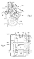
- FIG. 3 is a side view illustrating a further embodiment of the invention.
- FIG. 4 is a front elevational view of the equipment of FIG. 3 .
- the apparatus and process of the Prior Art is shown in diagrammatic fashion.
- the web 16 is fed to the anvil 14 at a speed such that the web speed of web 16 approximately equals the speed at which the outer periphery of anvil 14 is traveling.
- the anvil 14 may rotate at a slightly higher speed than the linear speed of the web 16 .
- the blades 34 of a rotary cutter 32 are also traveling at a peripheral speed equal to that of anvil 14 .
- a series of tabs 12 are carried on the outer surface of anvil 14 . Tabs 12 are held in place by vacuum provided within the interior of anvil 14 .
- the adhesive-coated surface of web 16 is facing outwardly while a non-tacky or uncoated surface engages the exterior anvil 14 .
- a web 10 is caused to travel in a path slightly displaced from the outer surface of rotating anvil 14 , but in close proximity thereto.
- a rotating wheel 38 which rotates at a peripheral velocity equal to the lineal velocity of web 10 , which, in turn, is substantially greater than the peripheral velocity of anvil 14 .
- Wheel 38 has a protrusion 36 which extends along its width.
- the rotational speed of roller 38 is selected so that the protrusion 36 engages web 10 and displaces it into contact with each successive adhesive-coated tab 12 .
- the slight displacement of web 10 causes it to come into contact with the tab segment 12 which, then, is instantly adhered to the higher speed traveling web 10 .
- the coefficient of friction between the uncoated side of tab 12 and the metal surface of anvil 14 is low so that the aggressive adhesion between tab 12 and web 10 together with the extremely low moment of inertia of tape tab segment 12 facilitates successful transfer of the tabs 12 to the web 10 , the tabs 12 accelerating almost instantly to the higher speed of web 10 .
- FIG. 2 the improved design of the present invention is shown in a side diagrammatic view. Near where the wheel 38 engages the web 10 with the protrusion 36 , a second wheel 40 with a second protrusion 42 is located. The second wheel 40 is located upstream of the first wheel 38 . Because the second wheel 40 is located upstream of the first wheel 38 , the vertical displacement of the web by the second protrusion 42 is greater than that of the first protrusion 36 . The second protrusion 42 will not interfere with the placement of the tab 12 b by the first protrusion 36 because the first protrusion 36 will have already made a rotation and the tab 12 b will have already traveled downstream.
- the second protrusion 42 allows placement of the tabs 12 a onto the web 10 at symmetrically spaced intervals with other tabs 12 a placed by the second protrusion 42 , but are asymmetrically spaced intervals relative to the tabs 12 b placed by the first protrusion 36 .
- web 10 is traveling to the left and adhesive-backed tape 16 is fed over a roller 121 onto an anvil/drum 114 .
- Tape web 16 is cut into individual tape tabs by a rotary cutter 132 .
- a lobe 136 located on a rotatable wheel 138 intermittently impacts the web 10 .
- a counterweight 139 located opposite of the lobe 136 on the rotatable wheel provides for an even rotation of the wheel 138 .
- a second rotatable wheel 140 holds a second lobe 142 that also intermittently impacts the web 10 .
- the second wheel 140 has a second counterweight 144 to balance the rotation of the second wheel 140 and counteract the second lobe 142 .
- the first wheel 138 and the second wheel 140 have the same cycle time, but will impact the web 10 at different times for preventing interference of the two wheels 138 and 140 .
- the second wheel 140 will impact the web 10 slightly farther upstream on the web 10 than the first wheel 138 impacts the web, thereby further preventing interference of the two wheels 138 and 140 .
- first wheel 138 impacts the web 10 first followed by impact of second wheel 150 .
- a motor or power supply 130 drives the apparatus, through various mechanical drive connections generally shown by dotted or phantom lines in FIG. 4 .
- FIG. 4 A front view of the embodiment of FIG. 3 is shown in FIG. 4 .
- a shaft 146 rotatably drives the rotatable anvil 114 .
- the rotary cutter 132 is mounted on another shaft 148 while the rotatable wheel 138 is mounted on a shaft 150 and the second rotatable wheel 140 mounted on another shaft 152 .
- the arrangement of the wheels 138 and 140 mounted on separate shafts 150 and 152 respectively, allows for position displacement of wheel 140 with respect to wheel 138 and for easier replacement of wheels 138 and 140 . Adjustment may be done on one of the wheels without necessarily needing to adjust the timing on the other wheel.
- the position of wheel 140 is adjustable, and the position of wheel 138 is fixed.
- the wheels 138 and 140 may be timed to have any spaced interval between them, provided that the interval is sufficient for the protuberances 136 and 142 to have sufficient clearance as they pass the web 10 .
Abstract
Description
Claims (20)
Priority Applications (1)
| Application Number | Priority Date | Filing Date | Title |
|---|---|---|---|
| US11/110,437 US7640962B2 (en) | 2004-04-20 | 2005-04-20 | Multiple tape application method and apparatus |
Applications Claiming Priority (2)
| Application Number | Priority Date | Filing Date | Title |
|---|---|---|---|
| US56363404P | 2004-04-20 | 2004-04-20 | |
| US11/110,437 US7640962B2 (en) | 2004-04-20 | 2005-04-20 | Multiple tape application method and apparatus |
Publications (2)
| Publication Number | Publication Date |
|---|---|
| US20050230056A1 US20050230056A1 (en) | 2005-10-20 |
| US7640962B2 true US7640962B2 (en) | 2010-01-05 |
Family
ID=35095060
Family Applications (1)
| Application Number | Title | Priority Date | Filing Date |
|---|---|---|---|
| US11/110,437 Active 2027-06-05 US7640962B2 (en) | 2004-04-20 | 2005-04-20 | Multiple tape application method and apparatus |
Country Status (1)
| Country | Link |
|---|---|
| US (1) | US7640962B2 (en) |
Cited By (33)
| Publication number | Priority date | Publication date | Assignee | Title |
|---|---|---|---|---|
| US20090242098A1 (en) * | 2008-03-12 | 2009-10-01 | Curt G. Joa, Inc. | Registered stretch laminate and methods for forming a registered stretch laminate |
| US20100327035A1 (en) * | 2006-05-18 | 2010-12-30 | Curt G. Joa, Inc. | Trim removal system |
| US20110088233A1 (en) * | 2006-05-18 | 2011-04-21 | Curt G. Joa, Inc. | Methods and apparatus for application of nested zero waste ear to traveling web |
| US20110155305A1 (en) * | 2009-12-30 | 2011-06-30 | Curt G. Joa, Inc. | Apparatus and method for producing absorbent article with stretch film side panel and application of intermittent discrete components of an absorbent article |
| US20110168326A1 (en) * | 2004-05-21 | 2011-07-14 | Curt G. Joa, Inc. | Method of producing a pants-type diaper |
| US8398793B2 (en) | 2007-07-20 | 2013-03-19 | Curt G. Joa, Inc. | Apparatus and method for minimizing waste and improving quality and production in web processing operations |
| US8417374B2 (en) | 2004-04-19 | 2013-04-09 | Curt G. Joa, Inc. | Method and apparatus for changing speed or direction of an article |
| USD684613S1 (en) | 2011-04-14 | 2013-06-18 | Curt G. Joa, Inc. | Sliding guard structure |
| US8656817B2 (en) | 2011-03-09 | 2014-02-25 | Curt G. Joa | Multi-profile die cutting assembly |
| US8663411B2 (en) | 2010-06-07 | 2014-03-04 | Curt G. Joa, Inc. | Apparatus and method for forming a pant-type diaper with refastenable side seams |
| US8673098B2 (en) | 2009-10-28 | 2014-03-18 | Curt G. Joa, Inc. | Method and apparatus for stretching segmented stretchable film and application of the segmented film to a moving web |
| USD703247S1 (en) | 2013-08-23 | 2014-04-22 | Curt G. Joa, Inc. | Ventilated vacuum commutation structure |
| USD703248S1 (en) | 2013-08-23 | 2014-04-22 | Curt G. Joa, Inc. | Ventilated vacuum commutation structure |
| USD703712S1 (en) | 2013-08-23 | 2014-04-29 | Curt G. Joa, Inc. | Ventilated vacuum commutation structure |
| USD703711S1 (en) | 2013-08-23 | 2014-04-29 | Curt G. Joa, Inc. | Ventilated vacuum communication structure |
| USD704237S1 (en) | 2013-08-23 | 2014-05-06 | Curt G. Joa, Inc. | Ventilated vacuum commutation structure |
| US8794115B2 (en) | 2007-02-21 | 2014-08-05 | Curt G. Joa, Inc. | Single transfer insert placement method and apparatus |
| US8820380B2 (en) | 2011-07-21 | 2014-09-02 | Curt G. Joa, Inc. | Differential speed shafted machines and uses therefor, including discontinuous and continuous side by side bonding |
| US9089453B2 (en) | 2009-12-30 | 2015-07-28 | Curt G. Joa, Inc. | Method for producing absorbent article with stretch film side panel and application of intermittent discrete components of an absorbent article |
| US9283683B2 (en) | 2013-07-24 | 2016-03-15 | Curt G. Joa, Inc. | Ventilated vacuum commutation structures |
| US9289329B1 (en) | 2013-12-05 | 2016-03-22 | Curt G. Joa, Inc. | Method for producing pant type diapers |
| US9387131B2 (en) | 2007-07-20 | 2016-07-12 | Curt G. Joa, Inc. | Apparatus and method for minimizing waste and improving quality and production in web processing operations by automated threading and re-threading of web materials |
| US9433538B2 (en) | 2006-05-18 | 2016-09-06 | Curt G. Joa, Inc. | Methods and apparatus for application of nested zero waste ear to traveling web and formation of articles using a dual cut slip unit |
| US9550306B2 (en) | 2007-02-21 | 2017-01-24 | Curt G. Joa, Inc. | Single transfer insert placement and apparatus with cross-direction insert placement control |
| US9566193B2 (en) | 2011-02-25 | 2017-02-14 | Curt G. Joa, Inc. | Methods and apparatus for forming disposable products at high speeds with small machine footprint |
| US9603752B2 (en) | 2010-08-05 | 2017-03-28 | Curt G. Joa, Inc. | Apparatus and method for minimizing waste and improving quality and production in web processing operations by automatic cuff defect correction |
| US9809414B2 (en) | 2012-04-24 | 2017-11-07 | Curt G. Joa, Inc. | Elastic break brake apparatus and method for minimizing broken elastic rethreading |
| US9944487B2 (en) | 2007-02-21 | 2018-04-17 | Curt G. Joa, Inc. | Single transfer insert placement method and apparatus |
| US10167156B2 (en) | 2015-07-24 | 2019-01-01 | Curt G. Joa, Inc. | Vacuum commutation apparatus and methods |
| US10456302B2 (en) | 2006-05-18 | 2019-10-29 | Curt G. Joa, Inc. | Methods and apparatus for application of nested zero waste ear to traveling web |
| WO2020036795A1 (en) | 2018-08-13 | 2020-02-20 | The Procter & Gamble Company | Method for bonding substrates |
| US10751220B2 (en) | 2012-02-20 | 2020-08-25 | Curt G. Joa, Inc. | Method of forming bonds between discrete components of disposable articles |
| US11737930B2 (en) | 2020-02-27 | 2023-08-29 | Curt G. Joa, Inc. | Configurable single transfer insert placement method and apparatus |
Families Citing this family (18)
| Publication number | Priority date | Publication date | Assignee | Title |
|---|---|---|---|---|
| US7703599B2 (en) | 2004-04-19 | 2010-04-27 | Curt G. Joa, Inc. | Method and apparatus for reversing direction of an article |
| US7708849B2 (en) | 2004-04-20 | 2010-05-04 | Curt G. Joa, Inc. | Apparatus and method for cutting elastic strands between layers of carrier webs |
| US20050230037A1 (en) | 2004-04-20 | 2005-10-20 | Curt G. Joa, Inc. | Staggered cutting knife |
| US7640962B2 (en) * | 2004-04-20 | 2010-01-05 | Curt G. Joa, Inc. | Multiple tape application method and apparatus |
| US7293593B2 (en) * | 2004-06-30 | 2007-11-13 | Delta Industrial Services, In. | Island placement technology |
| US8097110B2 (en) * | 2004-06-30 | 2012-01-17 | Delta Industrial Services, Inc. | Island placement technology |
| US7811403B2 (en) * | 2005-03-09 | 2010-10-12 | Curt G. Joa, Inc. | Transverse tab application method and apparatus |
| CA2600432C (en) * | 2005-03-09 | 2013-07-16 | Curt G. Joa, Inc. | Transverse tape application method and apparatus |
| US8007484B2 (en) | 2005-04-01 | 2011-08-30 | Curt G. Joa, Inc. | Pants type product and method of making the same |
| US7770712B2 (en) | 2006-02-17 | 2010-08-10 | Curt G. Joa, Inc. | Article transfer and placement apparatus with active puck |
| US8016972B2 (en) | 2007-05-09 | 2011-09-13 | Curt G. Joa, Inc. | Methods and apparatus for application of nested zero waste ear to traveling web |
| US8172977B2 (en) | 2009-04-06 | 2012-05-08 | Curt G. Joa, Inc. | Methods and apparatus for application of nested zero waste ear to traveling web |
| US20080060751A1 (en) * | 2006-09-07 | 2008-03-13 | Evan Arrindell | Island label apparatus and method |
| US20090294044A1 (en) * | 2008-05-27 | 2009-12-03 | Nathan Alan Gill | Methods and Apparatus for Attaching Elastic Components to Absorbent Articles |
| US9609920B2 (en) | 2013-09-06 | 2017-04-04 | Kimberly-Clark Worldwide, Inc. | Process for modifying a hook profile of a fastening component and a fastening component having hooks with a modified profile |
| US10308462B2 (en) * | 2013-09-06 | 2019-06-04 | Kimberly-Clark Worldwide, Inc. | Plate for an anvil roll with a reduced-vacuum region for use in a slip and cut system and method of using the same |
| CN104828626A (en) * | 2015-04-10 | 2015-08-12 | 安徽理工大学 | Automatic color card pasting equipment |
| CN114506091B (en) * | 2022-01-19 | 2024-02-23 | 江苏氢导智能装备有限公司 | Transfer mechanism and sheet-to-roll laminating device |
Citations (123)
| Publication number | Priority date | Publication date | Assignee | Title |
|---|---|---|---|---|
| US135145A (en) | 1873-01-21 | Improvement in paper-bag machines | ||
| US293353A (en) | 1884-02-12 | puryis | ||
| US312257A (en) | 1885-02-17 | hewes | ||
| US410123A (en) | 1889-08-27 | stilwell | ||
| US432742A (en) | 1890-07-22 | Paper-bag machinery | ||
| US643821A (en) | 1898-03-29 | 1900-02-20 | Union Paper Bag Machine Co | Machine for folding sides of satchel-bottomed bags. |
| US1393524A (en) | 1919-07-12 | 1921-10-11 | Endless Belt Corp Inc | Tipping mechanism |
| US1605842A (en) | 1926-11-02 | op bochesteb | ||
| US1686595A (en) | 1925-03-12 | 1928-10-09 | Dexter Folder Co | Sheet feeder |
| US1957651A (en) | 1932-06-06 | 1934-05-08 | Joa Curt G Inc | End fold mechanism |
| US2009857A (en) | 1932-09-30 | 1935-07-30 | Potdevin Machine Co | Machine for making envelopes and the like |
| US2054832A (en) | 1933-09-06 | 1936-09-22 | Potdevin Machine Co | Method of making bags |
| US2117432A (en) | 1935-02-07 | 1938-05-17 | Us Rubber Co | Process and apparatus for impregnating fibrous sheet material |
| US2128746A (en) | 1936-12-05 | 1938-08-30 | Joa Curt G Inc | Sanitary napkin machine |
| US2131808A (en) | 1935-12-16 | 1938-10-04 | Joa Curt G Inc | Sanitary napkin machine |
| US2164408A (en) | 1937-03-13 | 1939-07-04 | Joa Curt G Inc | Method of manufacturing sanitary napkins |
| US2167179A (en) | 1938-08-25 | 1939-07-25 | Joa Curt G Inc | Propulsion mechanism for conveyers |
| US2171741A (en) | 1936-06-02 | 1939-09-05 | Samcoe Holding Corp | Apparatus for synchronizing machines for handling tubular fabric |
| US2213431A (en) | 1938-03-31 | 1940-09-03 | Joa Curt G Inc | Sewed sanitary article and method of manufacture thereof |
| US2254291A (en) | 1937-10-30 | 1941-09-02 | Joa Curt G Inc | Stacking mechanism |
| US2254290A (en) | 1937-10-30 | 1941-09-02 | Joa Curt G Inc | Conveyer mechanism |
| US2282477A (en) | 1939-04-15 | 1942-05-12 | Joa Curt G Inc | Continuous bat assembly machine and method |
| US2286096A (en) | 1940-11-06 | 1942-06-09 | Joa Curt G Inc | Stile drilling apparatus |
| US2296931A (en) | 1937-10-30 | 1942-09-29 | Joa Curt G Inc | Manufacture of sanitary napkins and the like |
| US2304571A (en) | 1941-11-07 | 1942-12-08 | Joa Curt G Inc | Conveyer lubrication |
| US2324930A (en) | 1940-08-02 | 1943-07-20 | Joa Curt G Inc | Stacking and boxing apparatus |
| US2345937A (en) | 1940-08-01 | 1944-04-04 | Joa Curt G Inc | Feed for woodworking machines |
| US2466240A (en) | 1949-04-05 | |||
| US2481929A (en) | 1947-04-11 | 1949-09-13 | Joa Curt George | Sanitary napkin and method of fastening anchorage loops thereto |
| US2510229A (en) | 1948-04-19 | 1950-06-06 | Joa Curt George | Bat forming machine and method |
| US2540844A (en) | 1947-11-28 | 1951-02-06 | Allis Chalmers Mfg Co | Web folding machine |
| US2584002A (en) | 1950-11-28 | 1952-01-29 | Owens Illinois Glass Co | Method and apparatus for bonding closure materials |
| US2591359A (en) | 1950-06-14 | 1952-04-01 | Curt G Joa | Cellulose pad machine |
| US2618816A (en) | 1949-09-28 | 1952-11-25 | Curt G Joa | Bat forming apparatus and method |
| US2702406A (en) | 1950-12-13 | 1955-02-22 | Energized Materials Corp | Apparatus for stretching sheet material |
| US2721554A (en) | 1954-08-02 | 1955-10-25 | Joa Curt George | Sanitary napkin and absorbent pad which comprises a part thereof |
| US2730144A (en) | 1953-11-04 | 1956-01-10 | Curt G Joa | Automatic hopper feed for a wood working machine |
| US2772611A (en) | 1951-06-16 | 1956-12-04 | Us Envelope Co | Envelope making method and mechanism |
| US2780253A (en) | 1950-06-02 | 1957-02-05 | Curt G Joa | Self-centering feed rolls for a dowel machine or the like |
| US2785609A (en) | 1953-07-03 | 1957-03-19 | Milprint Inc | Art of producing lip-type bags |
| US2811905A (en) | 1956-02-29 | 1957-11-05 | Us Envelope Co | Envelope manufacture |
| US2839059A (en) | 1955-10-05 | 1958-06-17 | Curt G Joa | Method and apparatus for adhesively connecting the margins of a sanitary napkin wrapper about the pad |
| US2842169A (en) | 1957-03-15 | 1958-07-08 | Curt G Joa | Automatic feed for squaring work fed to the saw or saws of a tenoner |
| US2851934A (en) | 1957-07-10 | 1958-09-16 | Us Envelope Co | Manufacture of envelopes |
| US2875724A (en) | 1955-10-07 | 1959-03-03 | Curt G Joa | Apparatus for selective pattern impregnation or coating |
| US2913862A (en) | 1955-03-29 | 1959-11-24 | Circle Machinery & Supply Comp | Machine for forming and filling foil packets |
| US2939461A (en) | 1957-04-09 | 1960-06-07 | Curt G Joa | Sanitary napkins with external padding |
| US2960143A (en) | 1958-07-07 | 1960-11-15 | Curt G Joa | Machine for manufacturing sanitary napkins, or the like |
| US2990081A (en) | 1957-09-26 | 1961-06-27 | Minnesota Mining & Mfg | Application of tape to moving objects |
| US2991739A (en) | 1957-12-02 | 1961-07-11 | Joa Curt George | "teflon" faced shoe for the pressure foot of a sewing machine or the like |
| US3016207A (en) | 1958-12-15 | 1962-01-09 | Potter Instrument Co Inc | Vacuum loop tape handler |
| US3016582A (en) | 1957-02-14 | 1962-01-16 | Falls Paper & Power Company | Batt or mat forming apparatus |
| US3017795A (en) | 1957-06-06 | 1962-01-23 | Falls Paper & Power Company | Method and apparatus for forming individual wrapped pads from otherwise continuous batt strips |
| US3021135A (en) | 1959-08-10 | 1962-02-13 | Curt G Joa | Method and apparatus for cutting and folding paper or cloth webs |
| US3020687A (en) | 1958-09-15 | 1962-02-13 | Falls Paper & Power Company | Method and apparatus for forming individual wrapped pads from otherwise continuous batt strips |
| US3024957A (en) | 1959-01-05 | 1962-03-13 | Cons Electrodynamics Corp | Tape apparatus |
| US3053427A (en) | 1959-05-14 | 1962-09-11 | Potter Instrument Co Inc | Tape handling equipment |
| US3054516A (en) | 1960-08-19 | 1962-09-18 | Joa Curt George | Apparatus for stacking sheets |
| US3069982A (en) | 1960-02-11 | 1962-12-25 | Us Envelope Co | Manufacture of quick-opening envelopes or bags |
| US3087689A (en) | 1959-06-10 | 1963-04-30 | Heim Richard | Thread tensioning means for textile machines |
| US3091408A (en) | 1960-07-22 | 1963-05-28 | Potter Instrument Co Inc | Vacuum buffer loop device for tape handlers |
| US3114994A (en) | 1961-01-05 | 1963-12-24 | Curt G Joa | Embosser-knife unit |
| US3122293A (en) | 1961-01-03 | 1964-02-25 | Curt G Joa | Apparatus for forming individual pads from otherwise continuous batt strips |
| US3128206A (en) | 1959-05-06 | 1964-04-07 | Artof Maschb Dr Ing Meier Wind | Apparatus for a wet finishing process for continuous sheets of materials |
| US3203419A (en) | 1963-01-04 | 1965-08-31 | Curt G Joa | Sanitary napkin |
| US3230955A (en) | 1963-03-28 | 1966-01-25 | Joa Curt G Inc | Sanitary napkin |
| US3268954A (en) | 1963-12-09 | 1966-08-30 | Curt G Joa | Method for disintegrating wood pulp board into its component fibers and reassembling the fibers as a soft bat |
| US3288037A (en) | 1964-01-16 | 1966-11-29 | Berkley Machine Co | Side flap folding section of a rotary envelope making machine |
| US3289254A (en) | 1961-02-02 | 1966-12-06 | Curt G Joa | Machine for manufacturing sanitary napkins and the like |
| US3291131A (en) | 1963-07-19 | 1966-12-13 | Curt G Joa | Sanitary napkin, diaper, or hospital pad or the like |
| US3301114A (en) | 1964-11-25 | 1967-01-31 | Curt G Joa | Mat cutting machine with reciprocating belt feeder |
| US3322589A (en) | 1962-04-02 | 1967-05-30 | Curt G Joa | Sanitary napkin or the like and a method of manufacture thereof |
| US3342184A (en) | 1964-01-13 | 1967-09-19 | Curt G Joa | Sanitary napkin with attachment means and method of making |
| US3356092A (en) | 1964-11-20 | 1967-12-05 | Curt G Joa | Multi-ply pads or pad fillers |
| US3360103A (en) | 1966-07-07 | 1967-12-26 | Joa Curt G Inc | Turn-over apparatus |
| US3363847A (en) | 1964-11-12 | 1968-01-16 | Curt G. Joa | Waste disposer |
| US3391777A (en) | 1967-06-22 | 1968-07-09 | Curt G. Joa | Pad corner transfer machine |
| US3454442A (en) | 1965-10-19 | 1969-07-08 | Heller William C Jun | Art of thermally joining materials |
| US3470848A (en) | 1965-10-24 | 1969-10-07 | Donald F Dreher | Web coating apparatus |
| US3484275A (en) | 1965-05-17 | 1969-12-16 | Scott Paper Co | Electrostatic deposition of compositions on sheet materials utilizing pre-existing friction induced electrostatic charges on said sheet materials |
| US3502322A (en) | 1966-08-17 | 1970-03-24 | Broadbent & Sons Ltd Thomas | Folding of sheet material |
| US3521639A (en) | 1966-12-07 | 1970-07-28 | Curt G Joa | Sanitary napkin with completely wrapped filler pad |
| US3526563A (en) | 1966-10-10 | 1970-09-01 | Gloucester Eng Co Inc | Formations in continuous length materials |
| US3538551A (en) | 1968-05-15 | 1970-11-10 | Curt G Joa | Disc type fiberizer |
| US3540641A (en) | 1968-11-21 | 1970-11-17 | Celanese Corp | Web accumulator |
| US3575170A (en) | 1969-02-14 | 1971-04-20 | Plastronics Inc | Breather assembly for a sealed container |
| US3607578A (en) * | 1967-04-12 | 1971-09-21 | Moelnlycke Ab | Apparatus for producing disposable diapers |
| US3635462A (en) | 1970-08-21 | 1972-01-18 | Curt G Joa | Pad-folding machine |
| US3656741A (en) | 1970-04-03 | 1972-04-18 | Thomas F Macke | Folding apparatus |
| US3666611A (en) | 1969-08-15 | 1972-05-30 | Curt G Joa | Absorbent pad |
| US3673021A (en) | 1969-02-03 | 1972-06-27 | Curt G Joa | Method of making a laminated mat from plies of fibrous pulp material |
| US3685818A (en) | 1970-04-06 | 1972-08-22 | Kimberly Clark Co | Machine for making diapers |
| US3728191A (en) | 1971-03-19 | 1973-04-17 | Kimberly Clark Co | Waistband tape application for disposable diapers |
| US3751224A (en) | 1970-12-23 | 1973-08-07 | Messerschmitt Boelkow Blohm | Method and apparatus for a continuous fluid treatment of fibrous materials |
| US3772120A (en) * | 1971-11-05 | 1973-11-13 | Joa C Inc | Method for applying attaching tapes to pads |
| US3796360A (en) | 1972-09-27 | 1974-03-12 | Alexeff Snyder Ets | Combination storage festoon and compensator |
| US3816210A (en) | 1971-12-13 | 1974-06-11 | Taiyo Shokai Co Ltd | Method of and apparatus for automatically controlling transfer of filmstrips |
| US3847710A (en) * | 1972-04-26 | 1974-11-12 | Mo Och Domsjoe Ab | Apparatus for applying securing tabs to diapers, sanitary towels, compresses and similar absorbent bodies |
| US3854917A (en) | 1972-10-16 | 1974-12-17 | Owens Corning Fiberglass Corp | Method of and apparatus for processing flexible sheet material |
| US3883389A (en) | 1971-07-06 | 1975-05-13 | Gloucester Eng Co Inc | Continuous reciprocating web drive means working with intermittent heat seal forming means |
| US3888400A (en) | 1974-03-28 | 1975-06-10 | Littell Machine Co F J | Loop control apparatus for continuous strip material |
| US4316756A (en) * | 1980-08-15 | 1982-02-23 | Gff, Inc. | Method for bonding a pocket blank to a garment portion |
| GB2115775A (en) * | 1982-03-03 | 1983-09-14 | David John Instance | A label |
| US4589945A (en) * | 1985-07-05 | 1986-05-20 | Xerox Corporation | Vacuum supply control for a three pad labelling head machine |
| US4601771A (en) * | 1984-12-26 | 1986-07-22 | Labelette Company | Labeling machine attachment for applying pressure sensitive labels to round containers |
| US4675062A (en) * | 1984-05-18 | 1987-06-23 | Instance David John | Method and apparatus for making labels |
| US4701239A (en) * | 1985-10-15 | 1987-10-20 | Paper Converting Machine Company | Applicator for applying two or more tapes to a moving web |
| US4795510A (en) * | 1987-09-11 | 1989-01-03 | Kimberly-Clark Corporation | Process for applying reinforcing material to a diaper cover material |
| US4859945A (en) * | 1988-05-03 | 1989-08-22 | Elscint Ltd. | Optimized signal to noise ratio |
| US5429576A (en) * | 1994-04-08 | 1995-07-04 | Winkler & Dunnebier | Apparatus for making reusable adhesive envelopes |
| US5531850A (en) * | 1994-06-21 | 1996-07-02 | Paragon Trade Brands, Inc. | Apparatus and method for applying transverse tensioned elastic |
| US5746869A (en) * | 1993-10-14 | 1998-05-05 | The Procter & Gamble Company | Apparatus and process for cyclically accelerating and decelerating a strip of material |
| US20010017181A1 (en) * | 1998-06-26 | 2001-08-30 | S-Con, Inc. | Labeling apparatus with web registration, web cutting and carrier mechanisms, and methods thereof |
| US20020096241A1 (en) * | 1988-05-11 | 2002-07-25 | Instance David John | Method of and apparatus for producing labels |
| US6475325B1 (en) * | 2000-03-09 | 2002-11-05 | Curt G. Joa, Inc. | Tape tab applicator |
| US6524423B1 (en) * | 2000-03-07 | 2003-02-25 | Kimberly-Clark Worldwide, Inc. | Method of transferring a discrete portion of a first web onto a second web |
| US6684925B2 (en) * | 2000-11-15 | 2004-02-03 | Fuji Photo Film Co., Ltd. | Laminator and laminating method for lamination to substrate |
| US6820671B2 (en) * | 2001-10-05 | 2004-11-23 | Paragon Trade Brands, Inc. | Apparatus and method for assembling absorbent garments |
| US6852186B1 (en) * | 1998-04-20 | 2005-02-08 | Central Glass Co., Ltd. | Method and device for attaching adhesive tape |
| US6893528B2 (en) * | 2000-11-01 | 2005-05-17 | Adalis Corporation | Web material advance system for web material applicator |
| US20050230056A1 (en) * | 2004-04-20 | 2005-10-20 | Curt G. Joa, Inc. | Multiple tape application method and apparatus |
| US6978486B2 (en) * | 2002-07-02 | 2005-12-27 | Kimberly-Clark Worldwide, Inc. | Garment including an elastomeric composite laminate |
| US7452436B2 (en) * | 2005-03-09 | 2008-11-18 | Curt G. Joa, Inc. | Transverse tape application method and apparatus |
Family Cites Families (67)
| Publication number | Priority date | Publication date | Assignee | Title |
|---|---|---|---|---|
| US2346937A (en) * | 1942-08-19 | 1944-04-18 | Electric Storage Battery Co | Vent structure for cells employing liquid electrolytes |
| US3024857A (en) * | 1959-01-27 | 1962-03-13 | Saint Gobain | Device for filling containers with predetermined quantities of materials |
| US4002005A (en) * | 1973-06-19 | 1977-01-11 | Owens-Illinois, Inc. | Package of nested containers and method and apparatus for producing same |
| US4136535A (en) * | 1974-04-08 | 1979-01-30 | Audas Francis G | Padding apparatus for goods in web-form |
| US4003298A (en) * | 1975-02-10 | 1977-01-18 | Gloucester Engineering Co. Inc. | Apparatus for driving moving webs in bag making machines |
| US4009814A (en) * | 1975-09-08 | 1977-03-01 | Scott Paper Company | Web accumulator |
| US4081301A (en) * | 1975-10-30 | 1978-03-28 | The Procter & Gamble Company | Method and apparatus for continuously attaching discrete, stretched elastic strands to predetermined isolated portions of disposable abosrbent products |
| US4009815A (en) * | 1976-04-02 | 1977-03-01 | Gte Sylvania Incorporated | Apparatus for maintaining vertically moving strip at established tension |
| US4142626A (en) * | 1977-06-08 | 1979-03-06 | Paper Converting Machine Company | Accumulator for wound paper logs |
| US4141193A (en) * | 1977-07-12 | 1979-02-27 | Joa Curt G | Horizontal diaper grouper |
| US4141509A (en) * | 1978-01-06 | 1979-02-27 | Curt G. Joa, Inc. | Bale loader for fluff generator |
| FR2490079A1 (en) * | 1980-09-15 | 1982-03-19 | Boussac Saint Freres Bsf | PROCESS FOR MANUFACTURING CUTTING LAYERS AND CUTTING LAYERS OBTAINED BY CARRYING OUT SAID METHOD |
| US4374576A (en) * | 1981-02-02 | 1983-02-22 | Compensating Tension Controls, Inc. | Semi-automatic roll winding machine |
| US4501098A (en) * | 1982-07-19 | 1985-02-26 | Heritage Homes, Inc. | Hybrid home construction technique |
| US4492608A (en) * | 1983-01-06 | 1985-01-08 | Curt G. Joa, Inc. | Elastic band applicator and sheet folder |
| DE3421632C2 (en) * | 1984-06-09 | 1986-07-03 | Küsters, Eduard, 4150 Krefeld | Device for the oscillating linear drive of a component that interacts with a rotating roller or the like |
| DE3444331A1 (en) * | 1984-12-05 | 1986-06-05 | Winkler & Dünnebier, Maschinenfabrik und Eisengießerei GmbH & Co KG, 5450 Neuwied | METHOD AND DEVICE FOR APPLYING ELASTIC TAPES ON A MATERIAL RAIL |
| US4641381A (en) * | 1985-01-10 | 1987-02-10 | Kimberly-Clark Corporation | Disposable underpants, such as infant's training pants and the like |
| US4634482A (en) * | 1985-06-20 | 1987-01-06 | Curt G. Joa, Inc. | Method for securing elastic strands to disposable absorbent articles |
| US4726876A (en) * | 1985-10-18 | 1988-02-23 | Kimberly-Clark Corporation | Apparatus for repositioning discrete articles |
| US4650530A (en) * | 1986-03-10 | 1987-03-17 | Kimberly-Clark Corporation | Apparatus and method for folding, bonding and severing a web |
| IL82511A (en) * | 1986-05-28 | 1992-09-06 | Procter & Gamble | Apparatus for and methods of airlaying fibrous webs having discrete particles therein |
| US4908175A (en) * | 1986-05-28 | 1990-03-13 | The Procter & Gamble Company | Apparatus for and methods of forming airlaid fibrous webs having a multiplicity of components |
| US4726874A (en) * | 1987-03-31 | 1988-02-23 | Weyerhaeuser Company | Waist elastic applicator for diaper or similar article |
| FR2615166B1 (en) * | 1987-05-12 | 1989-08-11 | Sapal Plieuses Automatiques | PROCESS FOR PACKAGING A PRODUCT AND DEVICE FOR CARRYING OUT SAID PROCESS |
| US4802570A (en) * | 1987-09-14 | 1989-02-07 | Curt G. Joa, Inc. | Stacker with a yoke-type stripping device |
| US5876792A (en) * | 1988-03-14 | 1999-03-02 | Nextec Applications, Inc. | Methods and apparatus for controlled placement of a polymer composition into a web |
| US5000806A (en) * | 1988-04-19 | 1991-03-19 | Paper Converting Machine Company | Method and apparatus for applying an elastic strand to a disposable diaper |
| US4987940A (en) * | 1988-08-19 | 1991-01-29 | Minnesota Mining And Manufacturing Company | Cross web layer application device |
| US4892536A (en) * | 1988-09-02 | 1990-01-09 | The Procter & Gamble Company | Absorbent article having elastic strands |
| DE3830084A1 (en) * | 1988-09-03 | 1990-03-15 | Winkler Duennebier Kg Masch | METHOD AND DEVICE ON A MACHINE FOR THE PRODUCTION OF LETTER COVERS AND THE LIKE FOR FASTENING CLASPS |
| US5183252A (en) * | 1989-03-31 | 1993-02-02 | Eastman Kodak Company | Vaccum drum for different sized media |
| CA2025117C (en) * | 1989-09-13 | 2003-08-12 | Hironori Nomura | Method for manufacturing disposable garments |
| US6309487B1 (en) * | 1989-11-28 | 2001-10-30 | Robert M. Herrin | Disposable garments and method and apparatus for making |
| US5096532A (en) * | 1990-01-10 | 1992-03-17 | Kimberly-Clark Corporation | Ultrasonic rotary horn |
| JP2826185B2 (en) * | 1990-03-12 | 1998-11-18 | ユニ・チャーム株式会社 | Disposable pants-type wearing article |
| US5094658A (en) * | 1991-03-05 | 1992-03-10 | F.L. Smithe Machine Company, Inc. | Vacuum side-folder section for envelope blank folding apparatus |
| US5176244A (en) * | 1991-09-16 | 1993-01-05 | Curt G. Joa, Inc. | High speed variable count mechanical stacker |
| US5195684A (en) * | 1992-05-06 | 1993-03-23 | Curt G. Joa, Inc. | Screenless disk mill |
| US5409476A (en) * | 1993-08-11 | 1995-04-25 | Coates; Fredrica | Reusable diaper having gusseted pad insert |
| US5494622A (en) * | 1994-07-12 | 1996-02-27 | Kimberly-Clark Corporation | Apparatus and method for the zoned placement of superabsorbent material |
| US5659229A (en) * | 1995-01-31 | 1997-08-19 | Kimberly-Clark Worldwide, Inc. | Controlling web tension by actively controlling velocity of dancer roll |
| US5707470A (en) * | 1995-01-31 | 1998-01-13 | Kimberly-Clark Worldwide, Inc. | Rotary ultrasonic apparatus and methods |
| US5486253A (en) * | 1995-05-17 | 1996-01-23 | B&H Manufacturing Company | Method of labeling containers |
| US6336921B1 (en) * | 1995-05-31 | 2002-01-08 | Kimberly-Clark Worldwide, Inc. | Waist elastic system with improved elastic decay properties for a training pant |
| US5711832A (en) * | 1995-05-31 | 1998-01-27 | Kimberly-Clark Worldwide, Inc. | Process for making a training pant having a separate waist elastic system |
| US6551430B1 (en) * | 1995-05-31 | 2003-04-22 | Kimberly-Clark Worldwide, Inc. | Process for making a training pant having a unitary waist elastic system |
| IN187897B (en) * | 1995-06-15 | 2002-07-20 | Johnson & Johnson Inc | |
| US5876027A (en) * | 1995-06-15 | 1999-03-02 | Canon Aptex Inc. | Sheet bundle folding apparatus |
| US5865393A (en) * | 1995-07-14 | 1999-02-02 | Mannesmann Aktiengesellschaft | Vertical strip storage device |
| US5875202A (en) * | 1996-03-29 | 1999-02-23 | Adtran, Inc. | Transmission of encoded data over reliable digital communication link using enhanced error recovery mechanism |
| US5879500A (en) * | 1996-06-21 | 1999-03-09 | Herrin; Robert M. | Disposable undergarment forming apparatus and method of forming same |
| JP3184104B2 (en) * | 1996-11-06 | 2001-07-09 | ユニ・チャーム株式会社 | Disposable pants-type diapers |
| US6043836A (en) * | 1997-11-24 | 2000-03-28 | Eastman Kodak Company | Vacuum drum with countersunk holes |
| US6036805A (en) * | 1998-06-19 | 2000-03-14 | Kimberly-Clark Worldwide, Inc. | Method of making an asborbent article with prefastened side panels |
| US6856850B2 (en) * | 1998-07-03 | 2005-02-15 | Kimberly Clark Worldwide, Inc. | Controlling web tension, and accumulating lengths of web, using a festoon |
| US6183576B1 (en) * | 1999-05-27 | 2001-02-06 | Kimberly-Clark Worldwide, Inc. | Multiple path bonding |
| ATE261847T1 (en) * | 1999-12-03 | 2004-04-15 | Sig Pack Systems Ag | METHOD AND DEVICE FOR PRODUCING 3-SEALED BAG WITH A WELDED CLOSURE PROFILE |
| US6482278B1 (en) * | 2000-03-29 | 2002-11-19 | Curt G. Joa, Inc. | Pants type diaper and method for producing same |
| US6687120B2 (en) * | 2001-10-17 | 2004-02-03 | Dell Products L.P. | Computer system including speaker-antenna assembly |
| JP4379561B2 (en) * | 2001-01-30 | 2009-12-09 | キヤノンファインテック株式会社 | Sheet processing apparatus and image forming apparatus having the same |
| US6840616B2 (en) * | 2001-03-29 | 2005-01-11 | Scott Summers | Air folder adjuster apparatus and method |
| US7101587B2 (en) * | 2001-07-06 | 2006-09-05 | Kimberly-Clark Worldwide, Inc. | Method for wetting and winding a substrate |
| US20040007328A1 (en) * | 2002-07-15 | 2004-01-15 | Kimberly-Clark Worldwide, Inc. | Apparatus for cutting and placing limp pieces of material |
| JP2004149145A (en) * | 2002-10-30 | 2004-05-27 | Nippon Seiki Co Ltd | Filling and packaging machine |
| US7172666B2 (en) * | 2002-12-17 | 2007-02-06 | Groves Matthew E | Web material application methods and systems |
| US7172669B2 (en) * | 2003-03-07 | 2007-02-06 | Sca Hygiene Products Ab | Method for applying elastic members on a pant-shaped absorbent article |
-
2005
- 2005-04-20 US US11/110,437 patent/US7640962B2/en active Active
Patent Citations (124)
| Publication number | Priority date | Publication date | Assignee | Title |
|---|---|---|---|---|
| US135145A (en) | 1873-01-21 | Improvement in paper-bag machines | ||
| US293353A (en) | 1884-02-12 | puryis | ||
| US312257A (en) | 1885-02-17 | hewes | ||
| US410123A (en) | 1889-08-27 | stilwell | ||
| US432742A (en) | 1890-07-22 | Paper-bag machinery | ||
| US2466240A (en) | 1949-04-05 | |||
| US1605842A (en) | 1926-11-02 | op bochesteb | ||
| US643821A (en) | 1898-03-29 | 1900-02-20 | Union Paper Bag Machine Co | Machine for folding sides of satchel-bottomed bags. |
| US1393524A (en) | 1919-07-12 | 1921-10-11 | Endless Belt Corp Inc | Tipping mechanism |
| US1686595A (en) | 1925-03-12 | 1928-10-09 | Dexter Folder Co | Sheet feeder |
| US1957651A (en) | 1932-06-06 | 1934-05-08 | Joa Curt G Inc | End fold mechanism |
| US2009857A (en) | 1932-09-30 | 1935-07-30 | Potdevin Machine Co | Machine for making envelopes and the like |
| US2054832A (en) | 1933-09-06 | 1936-09-22 | Potdevin Machine Co | Method of making bags |
| US2117432A (en) | 1935-02-07 | 1938-05-17 | Us Rubber Co | Process and apparatus for impregnating fibrous sheet material |
| US2131808A (en) | 1935-12-16 | 1938-10-04 | Joa Curt G Inc | Sanitary napkin machine |
| US2171741A (en) | 1936-06-02 | 1939-09-05 | Samcoe Holding Corp | Apparatus for synchronizing machines for handling tubular fabric |
| US2128746A (en) | 1936-12-05 | 1938-08-30 | Joa Curt G Inc | Sanitary napkin machine |
| US2164408A (en) | 1937-03-13 | 1939-07-04 | Joa Curt G Inc | Method of manufacturing sanitary napkins |
| US2296931A (en) | 1937-10-30 | 1942-09-29 | Joa Curt G Inc | Manufacture of sanitary napkins and the like |
| US2254291A (en) | 1937-10-30 | 1941-09-02 | Joa Curt G Inc | Stacking mechanism |
| US2254290A (en) | 1937-10-30 | 1941-09-02 | Joa Curt G Inc | Conveyer mechanism |
| US2213431A (en) | 1938-03-31 | 1940-09-03 | Joa Curt G Inc | Sewed sanitary article and method of manufacture thereof |
| US2167179A (en) | 1938-08-25 | 1939-07-25 | Joa Curt G Inc | Propulsion mechanism for conveyers |
| US2282477A (en) | 1939-04-15 | 1942-05-12 | Joa Curt G Inc | Continuous bat assembly machine and method |
| US2345937A (en) | 1940-08-01 | 1944-04-04 | Joa Curt G Inc | Feed for woodworking machines |
| US2324930A (en) | 1940-08-02 | 1943-07-20 | Joa Curt G Inc | Stacking and boxing apparatus |
| US2286096A (en) | 1940-11-06 | 1942-06-09 | Joa Curt G Inc | Stile drilling apparatus |
| US2304571A (en) | 1941-11-07 | 1942-12-08 | Joa Curt G Inc | Conveyer lubrication |
| US2481929A (en) | 1947-04-11 | 1949-09-13 | Joa Curt George | Sanitary napkin and method of fastening anchorage loops thereto |
| US2540844A (en) | 1947-11-28 | 1951-02-06 | Allis Chalmers Mfg Co | Web folding machine |
| US2510229A (en) | 1948-04-19 | 1950-06-06 | Joa Curt George | Bat forming machine and method |
| US2618816A (en) | 1949-09-28 | 1952-11-25 | Curt G Joa | Bat forming apparatus and method |
| US2780253A (en) | 1950-06-02 | 1957-02-05 | Curt G Joa | Self-centering feed rolls for a dowel machine or the like |
| US2591359A (en) | 1950-06-14 | 1952-04-01 | Curt G Joa | Cellulose pad machine |
| US2584002A (en) | 1950-11-28 | 1952-01-29 | Owens Illinois Glass Co | Method and apparatus for bonding closure materials |
| US2702406A (en) | 1950-12-13 | 1955-02-22 | Energized Materials Corp | Apparatus for stretching sheet material |
| US2772611A (en) | 1951-06-16 | 1956-12-04 | Us Envelope Co | Envelope making method and mechanism |
| US2785609A (en) | 1953-07-03 | 1957-03-19 | Milprint Inc | Art of producing lip-type bags |
| US2730144A (en) | 1953-11-04 | 1956-01-10 | Curt G Joa | Automatic hopper feed for a wood working machine |
| US2721554A (en) | 1954-08-02 | 1955-10-25 | Joa Curt George | Sanitary napkin and absorbent pad which comprises a part thereof |
| US2913862A (en) | 1955-03-29 | 1959-11-24 | Circle Machinery & Supply Comp | Machine for forming and filling foil packets |
| US2839059A (en) | 1955-10-05 | 1958-06-17 | Curt G Joa | Method and apparatus for adhesively connecting the margins of a sanitary napkin wrapper about the pad |
| US2875724A (en) | 1955-10-07 | 1959-03-03 | Curt G Joa | Apparatus for selective pattern impregnation or coating |
| US2811905A (en) | 1956-02-29 | 1957-11-05 | Us Envelope Co | Envelope manufacture |
| US3086253A (en) | 1957-02-14 | 1963-04-23 | Falls Paper & Power Company | Method and apparatus for producing fibrous batts |
| US3016582A (en) | 1957-02-14 | 1962-01-16 | Falls Paper & Power Company | Batt or mat forming apparatus |
| US2842169A (en) | 1957-03-15 | 1958-07-08 | Curt G Joa | Automatic feed for squaring work fed to the saw or saws of a tenoner |
| US2939461A (en) | 1957-04-09 | 1960-06-07 | Curt G Joa | Sanitary napkins with external padding |
| US3017795A (en) | 1957-06-06 | 1962-01-23 | Falls Paper & Power Company | Method and apparatus for forming individual wrapped pads from otherwise continuous batt strips |
| US2851934A (en) | 1957-07-10 | 1958-09-16 | Us Envelope Co | Manufacture of envelopes |
| US2990081A (en) | 1957-09-26 | 1961-06-27 | Minnesota Mining & Mfg | Application of tape to moving objects |
| US2991739A (en) | 1957-12-02 | 1961-07-11 | Joa Curt George | "teflon" faced shoe for the pressure foot of a sewing machine or the like |
| US2960143A (en) | 1958-07-07 | 1960-11-15 | Curt G Joa | Machine for manufacturing sanitary napkins, or the like |
| US3020687A (en) | 1958-09-15 | 1962-02-13 | Falls Paper & Power Company | Method and apparatus for forming individual wrapped pads from otherwise continuous batt strips |
| US3016207A (en) | 1958-12-15 | 1962-01-09 | Potter Instrument Co Inc | Vacuum loop tape handler |
| US3024957A (en) | 1959-01-05 | 1962-03-13 | Cons Electrodynamics Corp | Tape apparatus |
| US3128206A (en) | 1959-05-06 | 1964-04-07 | Artof Maschb Dr Ing Meier Wind | Apparatus for a wet finishing process for continuous sheets of materials |
| US3053427A (en) | 1959-05-14 | 1962-09-11 | Potter Instrument Co Inc | Tape handling equipment |
| US3087689A (en) | 1959-06-10 | 1963-04-30 | Heim Richard | Thread tensioning means for textile machines |
| US3021135A (en) | 1959-08-10 | 1962-02-13 | Curt G Joa | Method and apparatus for cutting and folding paper or cloth webs |
| US3069982A (en) | 1960-02-11 | 1962-12-25 | Us Envelope Co | Manufacture of quick-opening envelopes or bags |
| US3091408A (en) | 1960-07-22 | 1963-05-28 | Potter Instrument Co Inc | Vacuum buffer loop device for tape handlers |
| US3054516A (en) | 1960-08-19 | 1962-09-18 | Joa Curt George | Apparatus for stacking sheets |
| US3122293A (en) | 1961-01-03 | 1964-02-25 | Curt G Joa | Apparatus for forming individual pads from otherwise continuous batt strips |
| US3114994A (en) | 1961-01-05 | 1963-12-24 | Curt G Joa | Embosser-knife unit |
| US3289254A (en) | 1961-02-02 | 1966-12-06 | Curt G Joa | Machine for manufacturing sanitary napkins and the like |
| US3322589A (en) | 1962-04-02 | 1967-05-30 | Curt G Joa | Sanitary napkin or the like and a method of manufacture thereof |
| US3203419A (en) | 1963-01-04 | 1965-08-31 | Curt G Joa | Sanitary napkin |
| US3230955A (en) | 1963-03-28 | 1966-01-25 | Joa Curt G Inc | Sanitary napkin |
| US3291131A (en) | 1963-07-19 | 1966-12-13 | Curt G Joa | Sanitary napkin, diaper, or hospital pad or the like |
| US3268954A (en) | 1963-12-09 | 1966-08-30 | Curt G Joa | Method for disintegrating wood pulp board into its component fibers and reassembling the fibers as a soft bat |
| US3342184A (en) | 1964-01-13 | 1967-09-19 | Curt G Joa | Sanitary napkin with attachment means and method of making |
| US3288037A (en) | 1964-01-16 | 1966-11-29 | Berkley Machine Co | Side flap folding section of a rotary envelope making machine |
| US3363847A (en) | 1964-11-12 | 1968-01-16 | Curt G. Joa | Waste disposer |
| US3356092A (en) | 1964-11-20 | 1967-12-05 | Curt G Joa | Multi-ply pads or pad fillers |
| US3301114A (en) | 1964-11-25 | 1967-01-31 | Curt G Joa | Mat cutting machine with reciprocating belt feeder |
| US3484275A (en) | 1965-05-17 | 1969-12-16 | Scott Paper Co | Electrostatic deposition of compositions on sheet materials utilizing pre-existing friction induced electrostatic charges on said sheet materials |
| US3454442A (en) | 1965-10-19 | 1969-07-08 | Heller William C Jun | Art of thermally joining materials |
| US3470848A (en) | 1965-10-24 | 1969-10-07 | Donald F Dreher | Web coating apparatus |
| US3360103A (en) | 1966-07-07 | 1967-12-26 | Joa Curt G Inc | Turn-over apparatus |
| US3502322A (en) | 1966-08-17 | 1970-03-24 | Broadbent & Sons Ltd Thomas | Folding of sheet material |
| US3526563A (en) | 1966-10-10 | 1970-09-01 | Gloucester Eng Co Inc | Formations in continuous length materials |
| US3521639A (en) | 1966-12-07 | 1970-07-28 | Curt G Joa | Sanitary napkin with completely wrapped filler pad |
| US3607578A (en) * | 1967-04-12 | 1971-09-21 | Moelnlycke Ab | Apparatus for producing disposable diapers |
| US3391777A (en) | 1967-06-22 | 1968-07-09 | Curt G. Joa | Pad corner transfer machine |
| US3538551A (en) | 1968-05-15 | 1970-11-10 | Curt G Joa | Disc type fiberizer |
| US3540641A (en) | 1968-11-21 | 1970-11-17 | Celanese Corp | Web accumulator |
| US3673021A (en) | 1969-02-03 | 1972-06-27 | Curt G Joa | Method of making a laminated mat from plies of fibrous pulp material |
| US3575170A (en) | 1969-02-14 | 1971-04-20 | Plastronics Inc | Breather assembly for a sealed container |
| US3666611A (en) | 1969-08-15 | 1972-05-30 | Curt G Joa | Absorbent pad |
| US3656741A (en) | 1970-04-03 | 1972-04-18 | Thomas F Macke | Folding apparatus |
| US3685818A (en) | 1970-04-06 | 1972-08-22 | Kimberly Clark Co | Machine for making diapers |
| US3635462A (en) | 1970-08-21 | 1972-01-18 | Curt G Joa | Pad-folding machine |
| US3751224A (en) | 1970-12-23 | 1973-08-07 | Messerschmitt Boelkow Blohm | Method and apparatus for a continuous fluid treatment of fibrous materials |
| US3728191A (en) | 1971-03-19 | 1973-04-17 | Kimberly Clark Co | Waistband tape application for disposable diapers |
| US3883389A (en) | 1971-07-06 | 1975-05-13 | Gloucester Eng Co Inc | Continuous reciprocating web drive means working with intermittent heat seal forming means |
| US3772120A (en) * | 1971-11-05 | 1973-11-13 | Joa C Inc | Method for applying attaching tapes to pads |
| US3816210A (en) | 1971-12-13 | 1974-06-11 | Taiyo Shokai Co Ltd | Method of and apparatus for automatically controlling transfer of filmstrips |
| US3847710A (en) * | 1972-04-26 | 1974-11-12 | Mo Och Domsjoe Ab | Apparatus for applying securing tabs to diapers, sanitary towels, compresses and similar absorbent bodies |
| US3796360A (en) | 1972-09-27 | 1974-03-12 | Alexeff Snyder Ets | Combination storage festoon and compensator |
| US3854917A (en) | 1972-10-16 | 1974-12-17 | Owens Corning Fiberglass Corp | Method of and apparatus for processing flexible sheet material |
| US3888400A (en) | 1974-03-28 | 1975-06-10 | Littell Machine Co F J | Loop control apparatus for continuous strip material |
| US4316756A (en) * | 1980-08-15 | 1982-02-23 | Gff, Inc. | Method for bonding a pocket blank to a garment portion |
| GB2115775A (en) * | 1982-03-03 | 1983-09-14 | David John Instance | A label |
| US4675062A (en) * | 1984-05-18 | 1987-06-23 | Instance David John | Method and apparatus for making labels |
| US4601771A (en) * | 1984-12-26 | 1986-07-22 | Labelette Company | Labeling machine attachment for applying pressure sensitive labels to round containers |
| US4589945A (en) * | 1985-07-05 | 1986-05-20 | Xerox Corporation | Vacuum supply control for a three pad labelling head machine |
| US4701239A (en) * | 1985-10-15 | 1987-10-20 | Paper Converting Machine Company | Applicator for applying two or more tapes to a moving web |
| US4795510A (en) * | 1987-09-11 | 1989-01-03 | Kimberly-Clark Corporation | Process for applying reinforcing material to a diaper cover material |
| US4859945A (en) * | 1988-05-03 | 1989-08-22 | Elscint Ltd. | Optimized signal to noise ratio |
| US20020096241A1 (en) * | 1988-05-11 | 2002-07-25 | Instance David John | Method of and apparatus for producing labels |
| US5746869A (en) * | 1993-10-14 | 1998-05-05 | The Procter & Gamble Company | Apparatus and process for cyclically accelerating and decelerating a strip of material |
| US5429576A (en) * | 1994-04-08 | 1995-07-04 | Winkler & Dunnebier | Apparatus for making reusable adhesive envelopes |
| US5531850A (en) * | 1994-06-21 | 1996-07-02 | Paragon Trade Brands, Inc. | Apparatus and method for applying transverse tensioned elastic |
| US6852186B1 (en) * | 1998-04-20 | 2005-02-08 | Central Glass Co., Ltd. | Method and device for attaching adhesive tape |
| US20010017181A1 (en) * | 1998-06-26 | 2001-08-30 | S-Con, Inc. | Labeling apparatus with web registration, web cutting and carrier mechanisms, and methods thereof |
| US6524423B1 (en) * | 2000-03-07 | 2003-02-25 | Kimberly-Clark Worldwide, Inc. | Method of transferring a discrete portion of a first web onto a second web |
| US6475325B1 (en) * | 2000-03-09 | 2002-11-05 | Curt G. Joa, Inc. | Tape tab applicator |
| US6893528B2 (en) * | 2000-11-01 | 2005-05-17 | Adalis Corporation | Web material advance system for web material applicator |
| US6684925B2 (en) * | 2000-11-15 | 2004-02-03 | Fuji Photo Film Co., Ltd. | Laminator and laminating method for lamination to substrate |
| US6820671B2 (en) * | 2001-10-05 | 2004-11-23 | Paragon Trade Brands, Inc. | Apparatus and method for assembling absorbent garments |
| US6978486B2 (en) * | 2002-07-02 | 2005-12-27 | Kimberly-Clark Worldwide, Inc. | Garment including an elastomeric composite laminate |
| US20050230056A1 (en) * | 2004-04-20 | 2005-10-20 | Curt G. Joa, Inc. | Multiple tape application method and apparatus |
| US7452436B2 (en) * | 2005-03-09 | 2008-11-18 | Curt G. Joa, Inc. | Transverse tape application method and apparatus |
Non-Patent Citations (7)
| Title |
|---|
| Office Action; Date Mailed: May 2, 2007; pp. 6; Cited Art; 1 Pg. |
| Office Action; Date Mailed: Nov. 14, 2007; pp. 7; Cited Art: 1 pg. |
| Office Action; Date Mailed: Nov. 2, 2006; pp. 4; Cited Art: 1 pg. |
| Reciprocating Mechanisms, Ingenious Mechanisms for Designers and Inventors, Franklin Jones vol. 1. |
| Response to Office Action; Amendment A; Dated: Feb. 5, 2007. |
| Response to Office Action; Amendment B; Dated: Sep. 4, 2007. |
| Response to Office Action; Amendment C; Dated: May 16, 2008. |
Cited By (49)
| Publication number | Priority date | Publication date | Assignee | Title |
|---|---|---|---|---|
| US8417374B2 (en) | 2004-04-19 | 2013-04-09 | Curt G. Joa, Inc. | Method and apparatus for changing speed or direction of an article |
| US8557077B2 (en) | 2004-05-21 | 2013-10-15 | Curt G. Joa, Inc. | Method of producing a pants-type diaper |
| US20110168326A1 (en) * | 2004-05-21 | 2011-07-14 | Curt G. Joa, Inc. | Method of producing a pants-type diaper |
| US20100327035A1 (en) * | 2006-05-18 | 2010-12-30 | Curt G. Joa, Inc. | Trim removal system |
| US20110088233A1 (en) * | 2006-05-18 | 2011-04-21 | Curt G. Joa, Inc. | Methods and apparatus for application of nested zero waste ear to traveling web |
| US10456302B2 (en) | 2006-05-18 | 2019-10-29 | Curt G. Joa, Inc. | Methods and apparatus for application of nested zero waste ear to traveling web |
| US9622918B2 (en) | 2006-05-18 | 2017-04-18 | Curt G. Joe, Inc. | Methods and apparatus for application of nested zero waste ear to traveling web |
| US8293056B2 (en) | 2006-05-18 | 2012-10-23 | Curt G. Joa, Inc. | Trim removal system |
| US9433538B2 (en) | 2006-05-18 | 2016-09-06 | Curt G. Joa, Inc. | Methods and apparatus for application of nested zero waste ear to traveling web and formation of articles using a dual cut slip unit |
| US8794115B2 (en) | 2007-02-21 | 2014-08-05 | Curt G. Joa, Inc. | Single transfer insert placement method and apparatus |
| US10266362B2 (en) | 2007-02-21 | 2019-04-23 | Curt G. Joa, Inc. | Single transfer insert placement method and apparatus |
| US9550306B2 (en) | 2007-02-21 | 2017-01-24 | Curt G. Joa, Inc. | Single transfer insert placement and apparatus with cross-direction insert placement control |
| US9944487B2 (en) | 2007-02-21 | 2018-04-17 | Curt G. Joa, Inc. | Single transfer insert placement method and apparatus |
| US9950439B2 (en) | 2007-02-21 | 2018-04-24 | Curt G. Joa, Inc. | Single transfer insert placement method and apparatus with cross-direction insert placement control |
| US8398793B2 (en) | 2007-07-20 | 2013-03-19 | Curt G. Joa, Inc. | Apparatus and method for minimizing waste and improving quality and production in web processing operations |
| US9387131B2 (en) | 2007-07-20 | 2016-07-12 | Curt G. Joa, Inc. | Apparatus and method for minimizing waste and improving quality and production in web processing operations by automated threading and re-threading of web materials |
| US8182624B2 (en) | 2008-03-12 | 2012-05-22 | Curt G. Joa, Inc. | Registered stretch laminate and methods for forming a registered stretch laminate |
| US20090242098A1 (en) * | 2008-03-12 | 2009-10-01 | Curt G. Joa, Inc. | Registered stretch laminate and methods for forming a registered stretch laminate |
| US10702428B2 (en) | 2009-04-06 | 2020-07-07 | Curt G. Joa, Inc. | Methods and apparatus for application of nested zero waste ear to traveling web |
| US8673098B2 (en) | 2009-10-28 | 2014-03-18 | Curt G. Joa, Inc. | Method and apparatus for stretching segmented stretchable film and application of the segmented film to a moving web |
| US9089453B2 (en) | 2009-12-30 | 2015-07-28 | Curt G. Joa, Inc. | Method for producing absorbent article with stretch film side panel and application of intermittent discrete components of an absorbent article |
| US20110155305A1 (en) * | 2009-12-30 | 2011-06-30 | Curt G. Joa, Inc. | Apparatus and method for producing absorbent article with stretch film side panel and application of intermittent discrete components of an absorbent article |
| US8460495B2 (en) | 2009-12-30 | 2013-06-11 | Curt G. Joa, Inc. | Method for producing absorbent article with stretch film side panel and application of intermittent discrete components of an absorbent article |
| US8663411B2 (en) | 2010-06-07 | 2014-03-04 | Curt G. Joa, Inc. | Apparatus and method for forming a pant-type diaper with refastenable side seams |
| USRE48182E1 (en) | 2010-08-05 | 2020-09-01 | Curt G. Joa, Inc. | Apparatus and method for minimizing waste and improving quality and production in web processing operations by automatic cuff defect correction |
| US9603752B2 (en) | 2010-08-05 | 2017-03-28 | Curt G. Joa, Inc. | Apparatus and method for minimizing waste and improving quality and production in web processing operations by automatic cuff defect correction |
| US9907706B2 (en) | 2011-02-25 | 2018-03-06 | Curt G. Joa, Inc. | Methods and apparatus for forming disposable products at high speeds with small machine footprint |
| US9566193B2 (en) | 2011-02-25 | 2017-02-14 | Curt G. Joa, Inc. | Methods and apparatus for forming disposable products at high speeds with small machine footprint |
| US8656817B2 (en) | 2011-03-09 | 2014-02-25 | Curt G. Joa | Multi-profile die cutting assembly |
| USD684613S1 (en) | 2011-04-14 | 2013-06-18 | Curt G. Joa, Inc. | Sliding guard structure |
| US8820380B2 (en) | 2011-07-21 | 2014-09-02 | Curt G. Joa, Inc. | Differential speed shafted machines and uses therefor, including discontinuous and continuous side by side bonding |
| US10751220B2 (en) | 2012-02-20 | 2020-08-25 | Curt G. Joa, Inc. | Method of forming bonds between discrete components of disposable articles |
| US9809414B2 (en) | 2012-04-24 | 2017-11-07 | Curt G. Joa, Inc. | Elastic break brake apparatus and method for minimizing broken elastic rethreading |
| US9908739B2 (en) | 2012-04-24 | 2018-03-06 | Curt G. Joa, Inc. | Apparatus and method for applying parallel flared elastics to disposable products and disposable products containing parallel flared elastics |
| US11034543B2 (en) | 2012-04-24 | 2021-06-15 | Curt G. Joa, Inc. | Apparatus and method for applying parallel flared elastics to disposable products and disposable products containing parallel flared elastics |
| US9283683B2 (en) | 2013-07-24 | 2016-03-15 | Curt G. Joa, Inc. | Ventilated vacuum commutation structures |
| USD704237S1 (en) | 2013-08-23 | 2014-05-06 | Curt G. Joa, Inc. | Ventilated vacuum commutation structure |
| USD703711S1 (en) | 2013-08-23 | 2014-04-29 | Curt G. Joa, Inc. | Ventilated vacuum communication structure |
| USD703712S1 (en) | 2013-08-23 | 2014-04-29 | Curt G. Joa, Inc. | Ventilated vacuum commutation structure |
| USD703248S1 (en) | 2013-08-23 | 2014-04-22 | Curt G. Joa, Inc. | Ventilated vacuum commutation structure |
| USD703247S1 (en) | 2013-08-23 | 2014-04-22 | Curt G. Joa, Inc. | Ventilated vacuum commutation structure |
| US9289329B1 (en) | 2013-12-05 | 2016-03-22 | Curt G. Joa, Inc. | Method for producing pant type diapers |
| US10633207B2 (en) | 2015-07-24 | 2020-04-28 | Curt G. Joa, Inc. | Vacuum commutation apparatus and methods |
| US10494216B2 (en) | 2015-07-24 | 2019-12-03 | Curt G. Joa, Inc. | Vacuum communication apparatus and methods |
| US10167156B2 (en) | 2015-07-24 | 2019-01-01 | Curt G. Joa, Inc. | Vacuum commutation apparatus and methods |
| WO2020036795A1 (en) | 2018-08-13 | 2020-02-20 | The Procter & Gamble Company | Method for bonding substrates |
| US11458690B2 (en) | 2018-08-13 | 2022-10-04 | The Procter & Gamble Company | Method and apparatus for bonding substrates |
| EP4212137A1 (en) | 2018-08-13 | 2023-07-19 | The Procter & Gamble Company | Method for bonding substrates |
| US11737930B2 (en) | 2020-02-27 | 2023-08-29 | Curt G. Joa, Inc. | Configurable single transfer insert placement method and apparatus |
Also Published As
| Publication number | Publication date |
|---|---|
| US20050230056A1 (en) | 2005-10-20 |
Similar Documents
| Publication | Publication Date | Title |
|---|---|---|
| US7640962B2 (en) | Multiple tape application method and apparatus | |
| US6475325B1 (en) | Tape tab applicator | |
| EP1868821B1 (en) | Transverse tape application method and apparatus | |
| EP1990302B1 (en) | Transverse tab application method and apparatus | |
| US7533709B2 (en) | High speed vacuum porting | |
| US11331223B2 (en) | Methods and apparatuses for assembling elastic laminates with different bond densities for absorbent articles | |
| JP4712713B2 (en) | Method and apparatus for placing parts in a moving web using a servo motor | |
| US3963557A (en) | Article transferring apparatus | |
| EP0723430B1 (en) | An apparatus and process for cyclically accelerating and decelerating a strip of material | |
| US5853117A (en) | Separator for linerless labels | |
| DK1994919T3 (en) | Method and device for using an embedded ear without waste for a running track | |
| EP0108173B1 (en) | Method and apparatus for applying elastic bands to webs | |
| US11905063B1 (en) | Systems and methods for cutting label material | |
| US7166179B2 (en) | Adhesive bandage pad module and method for making and applying adhesive bandage pads to a web | |
| US3954034A (en) | Rotary cutting mechanism | |
| JP4938176B2 (en) | Cutting and clamping device | |
| US6763749B2 (en) | Web speed metering apparatus and method | |
| JP4540819B2 (en) | Adhesive tape manufacturing and pasting system | |
| JP2012523357A (en) | Apparatus and method for placing pieces of tape material of desired length in a transverse orientation on a moving web material |
Legal Events
| Date | Code | Title | Description |
|---|---|---|---|
| AS | Assignment |
Owner name: CURT G. JOA, INC., WISCONSIN Free format text: ASSIGNMENT OF ASSIGNORS INTEREST;ASSIGNORS:MEYER, THOMAS C.;PARRISH, TIM;FRITZ, JEFF W.;REEL/FRAME:016725/0161;SIGNING DATES FROM 20050503 TO 20050527 |
|
| STCF | Information on status: patent grant |
Free format text: PATENTED CASE |
|
| FEPP | Fee payment procedure |
Free format text: PAT HOLDER CLAIMS SMALL ENTITY STATUS, ENTITY STATUS SET TO SMALL (ORIGINAL EVENT CODE: LTOS); ENTITY STATUS OF PATENT OWNER: SMALL ENTITY |
|
| FPAY | Fee payment |
Year of fee payment: 4 |
|
| FPAY | Fee payment |
Year of fee payment: 8 |
|
| MAFP | Maintenance fee payment |
Free format text: PAYMENT OF MAINTENANCE FEE, 12TH YR, SMALL ENTITY (ORIGINAL EVENT CODE: M2553); ENTITY STATUS OF PATENT OWNER: SMALL ENTITY Year of fee payment: 12 |