US7636879B2 - Error correction decoder - Google Patents
Error correction decoder Download PDFInfo
- Publication number
- US7636879B2 US7636879B2 US11/196,410 US19641005A US7636879B2 US 7636879 B2 US7636879 B2 US 7636879B2 US 19641005 A US19641005 A US 19641005A US 7636879 B2 US7636879 B2 US 7636879B2
- Authority
- US
- United States
- Prior art keywords
- path
- information
- trace
- likelihood
- state
- Prior art date
- Legal status (The legal status is an assumption and is not a legal conclusion. Google has not performed a legal analysis and makes no representation as to the accuracy of the status listed.)
- Expired - Fee Related, expires
Links
Images


Classifications
-
- H—ELECTRICITY
- H03—ELECTRONIC CIRCUITRY
- H03M—CODING; DECODING; CODE CONVERSION IN GENERAL
- H03M13/00—Coding, decoding or code conversion, for error detection or error correction; Coding theory basic assumptions; Coding bounds; Error probability evaluation methods; Channel models; Simulation or testing of codes
- H03M13/37—Decoding methods or techniques, not specific to the particular type of coding provided for in groups H03M13/03 - H03M13/35
- H03M13/39—Sequence estimation, i.e. using statistical methods for the reconstruction of the original codes
- H03M13/41—Sequence estimation, i.e. using statistical methods for the reconstruction of the original codes using the Viterbi algorithm or Viterbi processors
- H03M13/4161—Sequence estimation, i.e. using statistical methods for the reconstruction of the original codes using the Viterbi algorithm or Viterbi processors implementing path management
- H03M13/4169—Sequence estimation, i.e. using statistical methods for the reconstruction of the original codes using the Viterbi algorithm or Viterbi processors implementing path management using traceback
-
- H—ELECTRICITY
- H03—ELECTRONIC CIRCUITRY
- H03M—CODING; DECODING; CODE CONVERSION IN GENERAL
- H03M13/00—Coding, decoding or code conversion, for error detection or error correction; Coding theory basic assumptions; Coding bounds; Error probability evaluation methods; Channel models; Simulation or testing of codes
- H03M13/37—Decoding methods or techniques, not specific to the particular type of coding provided for in groups H03M13/03 - H03M13/35
- H03M13/39—Sequence estimation, i.e. using statistical methods for the reconstruction of the original codes
- H03M13/41—Sequence estimation, i.e. using statistical methods for the reconstruction of the original codes using the Viterbi algorithm or Viterbi processors
- H03M13/4138—Sequence estimation, i.e. using statistical methods for the reconstruction of the original codes using the Viterbi algorithm or Viterbi processors soft-output Viterbi algorithm based decoding, i.e. Viterbi decoding with weighted decisions
- H03M13/4146—Sequence estimation, i.e. using statistical methods for the reconstruction of the original codes using the Viterbi algorithm or Viterbi processors soft-output Viterbi algorithm based decoding, i.e. Viterbi decoding with weighted decisions soft-output Viterbi decoding according to Battail and Hagenauer in which the soft-output is determined using path metric differences along the maximum-likelihood path, i.e. "SOVA" decoding
Definitions
- the present invention relates to an error correction decoder for correcting transmission errors in encoded data that was received, and relates in particular to an error correction device utilizing a turbo-decoding method.
- turbo decoding method for example possessing high error correction performance
- the turbo decoding method includes two recursive systematic convolutional coders 1 and 2 reference numerals 104 and 106 , respectively.
- the convolutional coder 1 ( 104 ) encodes the signal from the information source in the order that it was input.
- the information source signals are accumulated temporarily in the memory, and are then extracted in sequence according to a pattern and their data sequence (signals) randomized by an interleaver ( 105 ) and then encoded by a convolutional coder 2 ( 106 ).
- the coded data U, Y 0 , Y 1 , Y 2 , Y 3 from the two coded outputs are sent on a channel ( 102 ).
- the coded data U′, Y 0 , Y 1 ′, Y 2 ′, Y 3 ′ is input by way of this channel ( 102 ) to the turbo decoder ( 103 ), and the decoded data U′′ restored by decoding the turbo code.
- the turbo decoder ( 103 ) includes decoders 1 , 2 ( 107 , 109 ) and, interleavers ( 108 , 111 ) and deinterleavers ( 110 , 112 ).
- decoder 1 U′, Y 0 ′, Y 1 ′ equivalent to the transmit data U, Y 0 , Y 1 is input and soft-decision decoding performed.
- Y 2 ′, Y 3 ′ are equivalent to the transmit data Y 2 , Y 3 from the interleaved and convolutional coded original signal X;
- the decoded data from the decoder 1 ( 107 ) is interleaved by the interleaver ( 108 ) so as to correspond to the Y 2 ′, Y 3 ′ and input to the decoder 2 ( 109 ), and soft-decision decoding performed.
- the output from the deinterleaver ( 110 ) that was deinterleaved to correspond to the original data sequence is once again input to the decoder 1 ( 107 ) as apriori likelihood (weight) information and the same operation repeated.
- the hard decision result output of the soft-decision decoding are deinterleaved by the deinterleaver ( 112 ) and acquired as the decoded output U′′. Randomly occurring random errors and burst errors occurring in bursts can be corrected by repeating this decoding process multiple times.
- the decoders 1 and 2 are identical so in this embodiment so that in many cases during actual use, the decoders are used by alternately switching one decoder between a decoder 1 (for example used at even-numbered times) and a decoder 2 (for example used at odd-numbered times).
- Typical decoding methods for the decoders 1 , 2 are for example, the MAP (Maximum A Posteriori) decoding method and the SOVA (Soft Output Viterbi Algorithm) decoding method.
- the MAP decoding method calculates the forward path metric a and the backward path metric by utilizing the shift rate of the received data, and by using the forward path metric a and the backward path metric b over time (bit), finds the differential soft decision value versus that larger probability (hard decision value) finds of becoming a “1” or a “0”.
- the SOVA decoding method is shown by Claude Berrou et al. in “A Low Complexity Soft-Output Viterbi Decoder Architecture”, Proc. IEEE, 1993 (non-patent document 2).
- a convolution coder conforming to 3GPP2 C. S0024-A and a trellis graph for that coder are shown in FIG. 2 using a convolutional coder as an example.
- tap state transitions in the convolution coder ( 201 ) and a state exists as 2 ⁇ (k ⁇ 1) when the constraint length is K.
- the convolutional coder K constraint length equals 4.
- FIG. 3 An overview of the trace-back operation in the SOVA decoding method is shown in FIG. 3 .
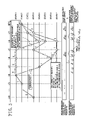
- FIG. 4 however shows a method that generates branches even on concurrent paths for trace-back, to improve the error correcting capability even from the third likely path onward as described by Marc P. C. Fossorier, Frank Burkert, Shu Lin, Joachim Hagenauer: “On the Equivalence Between SOVA and Max-Log-MAP Decodings”, IEEE Communication Letters, vol. 2, pp. 137-139, May 1998 (non-patent document 3)
- FIG. 4 is a graph for the operation of non-patent document 3.
- path- 1 is the survival path
- path- 2 , path-m are concurrent paths
- path-n is the branch from path- 2 serving as a concurrent path.
- Paths u j different from u j 1 are increased to account for the path-n, and by increasing potential paths, soft-decision output values are likely to have improved reliability.
- the number of branches from concurrent paths increase according to the length to where they merge with the survival path, so that there may be an enormous increase in the number of concurrent paths that must be traced at the same time.
- Non-patent document 1 “Near Shannon Limit Error—Correcting coding and decoding: Turbo-codes (1), Claude Berrou et al. Proc. IEEE 1993.
- the SOVA decoding method using parallel trace-back circuits (for example in JP-A No. 217748/2002) and the MAP method have a tradeoff relationship with error correction capability in terms of the operating frequency and the number of identical repeating decodings.
- Achieving a SOVA method possessing approximately the same error correcting capability as the MAP method requires either increasing the number of repetitive decodings where the decoding output is re-input to the decoder, or increasing the electrical power of the signal.
- Increasing the number of repeated decodings requires a high operating frequency due to the time required for decoding.
- Increasing the signal electrical power requires increasing the power consumption on the transmit side. Low power consumption is a critical issue in the case of mobile terminals so that the power consumption is a problem in either case.
- the present invention therefore has the object of providing a SOVA decoding method with high error correction performance and capable of operating at a low operating frequency, and on a reduced circuit scale.
- the present invention establishes the survival state flag of present state, survival state (weight), estimated binary input value, output path survival flag and path weight, based on the path information and difference of likelihood (or path metric) during ACS operation state, and the path weight and survival path flag on the input path.
- the output path weight (likelihood) prepares trace-back calculating sections (for selecting and outputting a weight state (weight state+difference in likelihood) according to the path information) that equal in number to the number of states and performs parallel processing.
- the trace-back calculating section of this invention as shown in FIG.
- the soft-decision candidates can in this way all be output during trace-back, and therefore soft decision values can be found with high accuracy.
- the technology of the related art required raising the operating frequency and increasing the number of trace-back circuits in order to improve error correction performance.
- this invention can achieve error correction performance equivalent to that of the MAP system while maintaining a low operating frequency.
- This invention renders the effect of improving error correction performance in turbo decoder utilizing the SOVA method to the same or higher standards than the MAP method, reduced the quantity of decoding processing calculations, and lowers the required operating frequency for digital signal processing.
- FIG. 1 is a block diagram of the communication system utilizing the turbo coding
- FIG. 2 is an example of the convolutional coder (supporting 3GPP2 C.S0024-A) and its trellis diagram;
- FIG. 3 is concept block diagram of the trace-back processing in the related art (SOVA method).
- FIG. 4 is a concept diagram of the trace-back processing of the related art (Bi-Directional SOVA method).
- FIG. 5 is a structural diagram of the turbo decoder of this invention.
- FIG. 6 is a block diagram for describing the operation during turbo repetitive decoding in this invention.
- FIG. 7 is a diagram of the turbo decoder ACS circuit of this invention.
- FIG. 8 is a diagram and table showing the method for calculating the branch metric of the turbo decoder ACS circuit of this invention.
- FIG. 9 is a diagram showing the trace-back circuit of the turbo decoder embodiment of this invention.
- FIG. 10 is a circuit diagram of the trace-back calculator section of the turbo decoder of this invention.
- FIG. 11 is a flow chart for the algorithm for determining the survival state flag and survival path flag in the trace-back circuit
- FIG. 12 is a flow chart for the algorithm for determining the path (or weight) information in the trace-back circuit
- FIG. 13 shows the output selector circuit of the turbo decoder of this invention
- FIG. 14 is a flow chart for the algorithm for determining the soft decision output and the decoding result (output) in the output selector circuit
- FIG. 15 is an overall concept diagram of the trace-back processing in this invention.
- FIG. 5 is a block diagram showing an embodiment of the turbo decoder ( 103 ) of this invention.
- This decoder is comprised of an input buffer memory 501 for storing received turbo coded data portions as soft decision inputs of the decoder; and a soft decision decoder 107 , and a decoder output memory 503 for storing as outputs, the soft decision values and hard decision values resulting from soft decision decoding, and an interleave controller 504 for controlling the addresses according to the interleave pattern sequence when making the specified number of repetitive calculations of decoding results and soft decision information, and an interleave pattern memory 505 for storing the interleave patterns.
- the functions of the interleavers 107 , 108 , and the deinterleavers 110 , 111 shown in FIG. 1 can be implemented by controlling the addresses according to the interleave pattern sequence with the interleave controller 504 , to regulate the flow of data according to the number of repetitive decodings.
- the soft decision decoder 107 contains a soft-output update unit 502 and a delay resistor 506 .
- the soft decision decoder 107 stores the a priori information for the next stage and the hard decision results from the input weight information delayed by the delay register 506 and output weight information from the soft output update unit 502 , into the decoder output memory 503 .
- the hard-decision output U′′ of the soft decision input U′ is obtained.
- the U′, Y 0 ′, Y 1 ′ that are values loaded in their address sequence from the input memory 501 where turbo coded data received via the channel is stored, are used as the C 0 , C 1 , C 2 inputs to the soft output update unit 502 .
- the external information weight L e (U′) n is set equal to ⁇ L(U′) n ⁇ U′ ⁇ L e (U′) n-1 ⁇ and written along with the hard decision results of L(U′) n in address sequence in the decoder output memory 503 .
- the apriori weight information L e (U′) n-1 is set to 0 at the first repetitive decoding.
- ⁇ is the weighting coefficient for the degree of reliability matching the soft decision value. This value affects the error correction characteristics.
- This coefficient ⁇ is used to measure the state of the noise on the channel from the bit error rate of the error correction results, to adaptively control the noise.
- the U′ which is a value loaded from the input memory 501 according to the interleave pattern by the interleaver 601 , is input as C 0 to the soft output update unit 502 ; and the values Y 2 ′, Y 3 ′ loaded in their address sequence are respectively used as C 1 , C 2 .
- the apriori weight information L e (U′) n-1 uses a value loaded according to the interleave pattern by the interleaver 602 from the decoder output memory 503 using the external information weight obtained in the prior decoding.
- the external information weight L e (U′) n is set equal to ⁇ L(U′) n ⁇ U′ ⁇ L e (U′) n-1 ⁇ and written along with the L e (U′) n hard decision results U′′ in the address according to the interleave pattern from the deinterleavers 603 , 604 in the decoder output memory 503 .
- the delay register 506 is a circuit for delaying operation until the output L e (U′) n from the soft output update unit 502 is found from the sum of the C 0 input to the soft output update unit 502 and the apriori weight information L e (U′) n-1 .
- addresses are generated in synchronization with the signal processing timing of the interleave controller 504 for each memory, so that the values read-out with interleave patterns in the address order of interleave pattern memory 505 , become the read-out address of the input memory 501 , and the read-out address and write address of the decoder output memory 503 , to achieve the functions of the interleavers 601 , 602 and the deinterleavers 603 , 604 .
- the interleavers 601 , 602 and the deinterleavers 603 , 604 of FIG. 6 are expressed by the interleave controller 504 and the interleave pattern memory 505 .
- the soft output update unit 502 of FIG. 5 includes an ACS (Add-Compare-Select) circuit 507 , and a state metric memory 508 for storing metric values found by the ACS circuit 507 , and a path information memory 902 for storing path values, and a Delta information memory 903 for storing the difference in likelihood, and a trace-backer 901 for following the path of the most likely transition from the path value.
- the soft output update unit 502 finds the transition likelihood (metric value), and transition information (path information), and delta (weight) information equivalent to the difference in likelihood for a transition from one state to another, for all the transition states.
- FIG. 7 An example of the embodiment of the ACS circuit 507 is shown in FIG. 7 .
- the ACS circuit 507 first of all finds the likelihood m of each transition branch for the basic state transition structure (butterfly), as a function of the C 0 , C 1 , C 2 inputs to the soft decision decoder.
- the metric values MET_P 0 , MET_P 1 corresponding to the binary states on the input side are loaded from the state metric memory 508 that stores the metric values of FIG. 5 , and metric values corresponding to the binary states on the input side are set in the ACS circuit.
- the MET_P 0 , MET_P 1 are metric values selected to correspond to the matching binary states on the input side of the ACS circuit.
- FIG. 7 shows that there is a transition to state 5 when a “0” input signal has been input for the state 2, and that there is also a transition to state 5 when a “1” input signal has been input for the state 3.
- there are two cases for a transition to the state 5 ; one case is a transition from a state 2 to a state 5 and the other is a transition from a state 3 to a state 5.
- the path D is larger than C in the example in FIG. 7 so that the transition from state 3 to state 5 is likely.
- examining the possibility for a shift at state 1 reveals that the transition from the state 2 to the state 1 in FIG. 7 is likely.
- the likely routes of state transitions are shown by a thick line in FIG. 7 .
- D possesses a larger transition likelihood than C, and so is defined by setting the path value to 1 since the transition is from a state with the larger state number. Conversely, when C is larger, then the path value is set to 0.
- the path value transitioning to the state 4 is set to 0 when A is larger than B, and is set to 1 when A is smaller than B.
- the value obtained after dividing the absolute value for the transition difference in likelihood between C and D by two, is set as the difference in likelihood (delta information) for state 5, and in the same way, the value obtained by dividing the absolute value of the difference between A and B by two, is set as the difference in likelihood (delta information) for state 1.
- the metric value, path value, difference in likelihood (delta information) for all states are found in the ACS circuit, and stored respectively in the state metric memory 508 , path memory 902 , and delta information memory 903 .
- the metric value having the largest maximum value one bit prior (state before transition) in the ACS circuit processing is stored, and after subtracting that stored metric value from each metric value, the value may be stored in the state metric memory 508 .
- the function for finding m from C 0 , C 1 , C 2 is determined according to the structure of the coder.
- One example of specifications for the 3GPP2 C.S 0024-A turbo coder are shown in the trellis diagram of FIG. 8 .
- FIG. 9 is a block diagram for describing the embodiment of the trace-back circuit.
- the initial state of the trace-back circuit 901 is set by the trace-back start flag, and the hard decision (binary output) value SIGN and soft decision value WGT (also called soft output) are found by using the path values and difference in likelihood (or delta information) for each state output respectively from the path memory 902 and delta information memory 903 .
- SIGN binary output
- WGT also called soft output
- the trace-back circuit 901 is comprised of multiple trace units 904 and one output selector 905 .
- the trace unit 904 is a circuit for finding the survival path flag for the current state, the hard decision value SIGN (binary output), the soft decision output WGT, and the path weight information and survival path flag for each output path based on the path weight information and the survival path flag for each input state.
- the survival path flag is a flag expressing the most likely path transition
- the survival state flag is a flag expressing the input state on the survival path.
- the information found in each trace unit 904 applies feedback according to the trellis state transition as one bit prior (state before transition) information in the trace unit 904 . For example, as shown in the trellis diagram of FIG.
- the output selector 905 calculates the hard decision value SIGN (binary output) and the soft decision (or soft output) WGT from the results output from each trace unit 904 .
- FIG. 10 shows an example of the structure of the trace unit 904 .
- the trace unit 904 possesses three functions. These functions are determining the survival state flag ⁇ survival path flag; determining the weight information (delta information), and determining the hard decision setting (binary output).
- the first function of the trace unit 904 which is determining the flags is shown in the operating flowchart in FIG. 11 .
- First of all the survival state flag is found.
- the survival state flag is determined by the sum of their logic values.
- the survival path flag for the output path is determined based on the survival state flag that was found.
- the survival path flag for the output path is set to equal one, based on path information for a state where the survival state flag equals one, and for all other paths the survival path flag is set to equal zero.
- FIG. 12 is an operation flow chart for setting the weight for the second function of the trace unit 904 .
- the weight of the current state is determined from the path weight of the two input paths for trace-back to its own state. The smaller the path weight, the higher the reliability so that minimum values of input path weights are selected to set the weight.
- the weights for each output path are determined by the path information and the difference in likelihood (delta information) from the delta information memory and the weight that was found.
- the output path weight is the weight state when conforming to path information, and is (weight state+difference in likelihood) when not conforming to path information.
- the path weight when determining the path weight output to a lower-numbered state, the path weight is set equal to the (weight state) when the path information equals zero; and the path weight is set equal to (weight state+difference in likelihood) when the path information equals one.
- the weight state initial value is 0 for the survival state, and is a maximum value in all other states. In this case, the weight and the survival path weight both become zero.
- the third function of the trace unit 904 is to output current state hard decision values (binary output) based on the path information. As shown in the trellis diagram in FIG. 2 , the relation between the path information and hard decision values (binary output) change according to the state number so that based on the path information and state number the binary output decision 1001 determines the hard decision value and outputs it.
- FIG. 13 shows the structure of the output selector.
- the output selector determines the hard decision value SIGN (binary output) for that bit and the soft decision value (soft output) WGT as its path information, based on the hard decision values for each state, the survival state flag, and the path difference in likelihood.
- the WGT is made the decoder result path (state path) 1404 (In other words, WGT is output as a soft output candidate.)
- state path path results (weight state+difference in likelihood ⁇ or WGT+DLTA ⁇ ) opposing the decoder results are output ( 1405 ).
- the candidate values that are obtained, show the path difference in likelihood for results opposing the hard decision (binary) outputs for that bit, so those minimum values are set as the soft decision WGT output from the output selector ( 1406 ).
- the state of the trace-back in the above described configuration is shown in FIG. 15 .
- the paths and opposing paths are output according to the path information from each state, and all output paths per transitions between bits are considered.
- the number of output paths increases per one bit transition however there are paths converging towards the same state, and thereafter there is no need to trace back on paths with lower reliability (will not become output candidates since reliability is always worse on other side.) so that the number of required trace-back circuits is limited to the number of states.
Abstract
Description
Claims (7)
Applications Claiming Priority (2)
| Application Number | Priority Date | Filing Date | Title |
|---|---|---|---|
| JP2005-008512 | 2005-01-17 | ||
| JP2005008512A JP4432781B2 (en) | 2005-01-17 | 2005-01-17 | Error correction decoder |
Publications (2)
| Publication Number | Publication Date |
|---|---|
| US20060161834A1 US20060161834A1 (en) | 2006-07-20 |
| US7636879B2 true US7636879B2 (en) | 2009-12-22 |
Family
ID=36685376
Family Applications (1)
| Application Number | Title | Priority Date | Filing Date |
|---|---|---|---|
| US11/196,410 Expired - Fee Related US7636879B2 (en) | 2005-01-17 | 2005-08-04 | Error correction decoder |
Country Status (3)
| Country | Link |
|---|---|
| US (1) | US7636879B2 (en) |
| JP (1) | JP4432781B2 (en) |
| CN (1) | CN1808912B (en) |
Cited By (4)
| Publication number | Priority date | Publication date | Assignee | Title |
|---|---|---|---|---|
| US20080152044A1 (en) * | 2006-12-20 | 2008-06-26 | Media Tek Inc. | Veterbi decoding method for convolutionally encoded signal |
| US20090041166A1 (en) * | 2007-08-09 | 2009-02-12 | Mbit Wireless, Inc. | Method and apparatus to improve information decoding when its characteristics are known a priori |
| US20100031130A1 (en) * | 2008-08-04 | 2010-02-04 | Legend Silicon Corp. | Forward error correction (fec) and variable length code (vlc) joint decoding |
| US20110211660A1 (en) * | 2010-02-27 | 2011-09-01 | Topcon Positioning Systems, Inc. | Multi -channel sequential viterbi decoder |
Families Citing this family (12)
| Publication number | Priority date | Publication date | Assignee | Title |
|---|---|---|---|---|
| US20070127458A1 (en) * | 2005-12-06 | 2007-06-07 | Micrel, Inc. | Data communication method for detecting slipped bit errors in received data packets |
| CN101584121B (en) * | 2007-01-16 | 2014-10-29 | 皇家飞利浦电子股份有限公司 | System, apparatus and method for interleaving data bits or symbols |
| CN101145789B (en) * | 2007-07-23 | 2011-06-29 | 华东师范大学 | High-speed residual path management module of Viterbi decoder |
| FR2922699A1 (en) * | 2007-10-18 | 2009-04-24 | Canon Kk | ITERATIVE DECODING IN A MESH NETWORK, CORRESPONDING METHOD AND SYSTEM |
| JP2011135163A (en) * | 2009-12-22 | 2011-07-07 | Fujitsu Ltd | Decoding method |
| TWI394378B (en) * | 2010-05-17 | 2013-04-21 | Novatek Microelectronics Corp | Viterbi decoder and writing and reading method |
| CN102142849B (en) * | 2011-02-15 | 2014-07-30 | 无锡物联网产业研究院 | Viterbi decoding method and Viterbi decoder |
| JP6155959B2 (en) | 2013-08-19 | 2017-07-05 | 富士通株式会社 | Decoding device and decoding method |
| TWI569589B (en) * | 2015-05-13 | 2017-02-01 | 晨星半導體股份有限公司 | Viterbi decoding apparatus and viterbi decoding method |
| CN106301395A (en) * | 2015-06-10 | 2017-01-04 | 晨星半导体股份有限公司 | Veterbi decoding device and Veterbi decoding method |
| CN109245856B (en) * | 2018-09-20 | 2021-03-09 | 中国人民解放军海军航空大学 | Return-to-zero Turbo code length and frame synchronization identification method based on differential likelihood difference |
| US11533126B1 (en) | 2021-08-20 | 2022-12-20 | Cisco Technology, Inc. | Soft-output Viterbi equalizer for non-binary modulation |
Citations (29)
| Publication number | Priority date | Publication date | Assignee | Title |
|---|---|---|---|---|
| US5375129A (en) * | 1990-07-19 | 1994-12-20 | Technophone Limited | Maximum likelihood sequence detector |
| US5432820A (en) * | 1990-11-19 | 1995-07-11 | Fujitsu Limited | Maximum-likelihood decoding method and device |
| US5502735A (en) * | 1991-07-16 | 1996-03-26 | Nokia Mobile Phones (U.K.) Limited | Maximum likelihood sequence detector |
| US5859861A (en) * | 1995-06-21 | 1999-01-12 | Hyundai Electronics Ind. Co., Ltd. | High speed viterbi decoder |
| US5946361A (en) * | 1994-06-23 | 1999-08-31 | Oki Electric Industry Co., Ltd. | Viterbi decoding method and circuit with accelerated back-tracing and efficient path metric calculation |
| US5974091A (en) * | 1997-10-30 | 1999-10-26 | Communication Network Systems | Composite trellis system and method |
| US5991343A (en) * | 1997-01-20 | 1999-11-23 | Hyundai Electronics Ind Co., Ltd. | Trellis decoder of a DTV |
| US5995562A (en) * | 1995-10-25 | 1999-11-30 | Nec Corporation | Maximum-likelihood decoding |
| US6031876A (en) * | 1996-06-29 | 2000-02-29 | Hyundai Electronics Ind Co., Ltd. | Trellis decoder for ATSC 8VSB |
| US6088404A (en) * | 1997-04-30 | 2000-07-11 | Daewoo Electronics Co., Ltd. | Method and apparatus for decoding trellis code data |
| US6094739A (en) * | 1997-09-24 | 2000-07-25 | Lucent Technologies, Inc. | Trellis decoder for real-time video rate decoding and de-interleaving |
| US6108811A (en) * | 1996-10-18 | 2000-08-22 | Mitsubishi Denki Kabushiki Kaisha | Error-correcting decoder continuously adding flag signals to locations preceding a first location at which a difference between path metrics is lower than the threshold |
| US6134697A (en) * | 1997-11-29 | 2000-10-17 | Daewoo Electronics Co., Ltd. | Traceback processor for use in a trellis-coded modulation decoder |
| US6141384A (en) * | 1997-02-14 | 2000-10-31 | Philips Electronics North America Corporation | Decoder for trellis encoded interleaved data stream and HDTV receiver including such a decoder |
| JP2000341137A (en) * | 1999-05-28 | 2000-12-08 | Sony Corp | Decoder |
| JP2002217748A (en) * | 2001-01-17 | 2002-08-02 | Hitachi Ltd | Error correction decoder |
| US6445755B1 (en) * | 1999-09-14 | 2002-09-03 | Samsung Electronics Co, Ltd. | Two-step soft output viterbi algorithm decoder using modified trace back |
| US6477680B2 (en) * | 1998-06-26 | 2002-11-05 | Agere Systems Inc. | Area-efficient convolutional decoder |
| US6484283B2 (en) * | 1998-12-30 | 2002-11-19 | International Business Machines Corporation | Method and apparatus for encoding and decoding a turbo code in an integrated modem system |
| US6487694B1 (en) * | 1999-12-20 | 2002-11-26 | Hitachi America, Ltd. | Method and apparatus for turbo-code decoding a convolution encoded data frame using symbol-by-symbol traceback and HR-SOVA |
| US6668026B1 (en) * | 1999-05-28 | 2003-12-23 | Sony Corporation | Decoding method and apparatus |
| US6690737B1 (en) * | 1998-12-31 | 2004-02-10 | Samsung Electronics Co., Ltd. | Device and method for determining maximum likelihood state in a decoding device |
| US6697443B1 (en) * | 1999-10-05 | 2004-02-24 | Samsung Electronics Co., Ltd. | Component decoder and method thereof in mobile communication system |
| US7032163B2 (en) * | 2001-07-06 | 2006-04-18 | Hitachi, Ltd. | Error correction decoder for turbo code |
| US7085992B2 (en) * | 2000-10-24 | 2006-08-01 | Infineon Technologies Ag | Method and device for decoding a sequence of physical signals, reliability detection unit and viterbi decoding unit |
| US7120207B2 (en) * | 2001-12-31 | 2006-10-10 | Nokia Corporation | Transmission method and radio receiver |
| US7222288B2 (en) * | 2004-07-30 | 2007-05-22 | Hellosoft, Inc. | Modified soft output Viterbi algorithm for truncated trellis |
| US7237180B1 (en) * | 2002-10-07 | 2007-06-26 | Maxtor Corporation | Symbol-level soft output Viterbi algorithm (SOVA) and a simplification on SOVA |
| US7246298B2 (en) * | 2003-11-24 | 2007-07-17 | Via Technologies, Inc. | Unified viterbi/turbo decoder for mobile communication systems |
Family Cites Families (2)
| Publication number | Priority date | Publication date | Assignee | Title |
|---|---|---|---|---|
| JP3846527B2 (en) * | 1999-07-21 | 2006-11-15 | 三菱電機株式会社 | Turbo code error correction decoder, turbo code error correction decoding method, turbo code decoding apparatus, and turbo code decoding system |
| CN1142629C (en) * | 1999-12-23 | 2004-03-17 | 华为技术有限公司 | Decoding method and decoder for Tebo code |
-
2005
- 2005-01-17 JP JP2005008512A patent/JP4432781B2/en not_active Expired - Fee Related
- 2005-08-04 US US11/196,410 patent/US7636879B2/en not_active Expired - Fee Related
- 2005-08-05 CN CN2005100897287A patent/CN1808912B/en not_active Expired - Fee Related
Patent Citations (30)
| Publication number | Priority date | Publication date | Assignee | Title |
|---|---|---|---|---|
| US5375129A (en) * | 1990-07-19 | 1994-12-20 | Technophone Limited | Maximum likelihood sequence detector |
| US5432820A (en) * | 1990-11-19 | 1995-07-11 | Fujitsu Limited | Maximum-likelihood decoding method and device |
| US5502735A (en) * | 1991-07-16 | 1996-03-26 | Nokia Mobile Phones (U.K.) Limited | Maximum likelihood sequence detector |
| US5946361A (en) * | 1994-06-23 | 1999-08-31 | Oki Electric Industry Co., Ltd. | Viterbi decoding method and circuit with accelerated back-tracing and efficient path metric calculation |
| US5859861A (en) * | 1995-06-21 | 1999-01-12 | Hyundai Electronics Ind. Co., Ltd. | High speed viterbi decoder |
| US5960011A (en) * | 1995-06-30 | 1999-09-28 | Hyundai Electrinics Ind. Co., Ltd. | Viterbi decoder |
| US5995562A (en) * | 1995-10-25 | 1999-11-30 | Nec Corporation | Maximum-likelihood decoding |
| US6031876A (en) * | 1996-06-29 | 2000-02-29 | Hyundai Electronics Ind Co., Ltd. | Trellis decoder for ATSC 8VSB |
| US6108811A (en) * | 1996-10-18 | 2000-08-22 | Mitsubishi Denki Kabushiki Kaisha | Error-correcting decoder continuously adding flag signals to locations preceding a first location at which a difference between path metrics is lower than the threshold |
| US5991343A (en) * | 1997-01-20 | 1999-11-23 | Hyundai Electronics Ind Co., Ltd. | Trellis decoder of a DTV |
| US6141384A (en) * | 1997-02-14 | 2000-10-31 | Philips Electronics North America Corporation | Decoder for trellis encoded interleaved data stream and HDTV receiver including such a decoder |
| US6088404A (en) * | 1997-04-30 | 2000-07-11 | Daewoo Electronics Co., Ltd. | Method and apparatus for decoding trellis code data |
| US6094739A (en) * | 1997-09-24 | 2000-07-25 | Lucent Technologies, Inc. | Trellis decoder for real-time video rate decoding and de-interleaving |
| US5974091A (en) * | 1997-10-30 | 1999-10-26 | Communication Network Systems | Composite trellis system and method |
| US6134697A (en) * | 1997-11-29 | 2000-10-17 | Daewoo Electronics Co., Ltd. | Traceback processor for use in a trellis-coded modulation decoder |
| US6477680B2 (en) * | 1998-06-26 | 2002-11-05 | Agere Systems Inc. | Area-efficient convolutional decoder |
| US6484283B2 (en) * | 1998-12-30 | 2002-11-19 | International Business Machines Corporation | Method and apparatus for encoding and decoding a turbo code in an integrated modem system |
| US6690737B1 (en) * | 1998-12-31 | 2004-02-10 | Samsung Electronics Co., Ltd. | Device and method for determining maximum likelihood state in a decoding device |
| JP2000341137A (en) * | 1999-05-28 | 2000-12-08 | Sony Corp | Decoder |
| US6668026B1 (en) * | 1999-05-28 | 2003-12-23 | Sony Corporation | Decoding method and apparatus |
| US6445755B1 (en) * | 1999-09-14 | 2002-09-03 | Samsung Electronics Co, Ltd. | Two-step soft output viterbi algorithm decoder using modified trace back |
| US6697443B1 (en) * | 1999-10-05 | 2004-02-24 | Samsung Electronics Co., Ltd. | Component decoder and method thereof in mobile communication system |
| US6487694B1 (en) * | 1999-12-20 | 2002-11-26 | Hitachi America, Ltd. | Method and apparatus for turbo-code decoding a convolution encoded data frame using symbol-by-symbol traceback and HR-SOVA |
| US7085992B2 (en) * | 2000-10-24 | 2006-08-01 | Infineon Technologies Ag | Method and device for decoding a sequence of physical signals, reliability detection unit and viterbi decoding unit |
| JP2002217748A (en) * | 2001-01-17 | 2002-08-02 | Hitachi Ltd | Error correction decoder |
| US7032163B2 (en) * | 2001-07-06 | 2006-04-18 | Hitachi, Ltd. | Error correction decoder for turbo code |
| US7120207B2 (en) * | 2001-12-31 | 2006-10-10 | Nokia Corporation | Transmission method and radio receiver |
| US7237180B1 (en) * | 2002-10-07 | 2007-06-26 | Maxtor Corporation | Symbol-level soft output Viterbi algorithm (SOVA) and a simplification on SOVA |
| US7246298B2 (en) * | 2003-11-24 | 2007-07-17 | Via Technologies, Inc. | Unified viterbi/turbo decoder for mobile communication systems |
| US7222288B2 (en) * | 2004-07-30 | 2007-05-22 | Hellosoft, Inc. | Modified soft output Viterbi algorithm for truncated trellis |
Non-Patent Citations (3)
| Title |
|---|
| "A Low Complexity Soft-Output Viterbi Decoder Architecture" by Berrou, et al. pp. 737-740. IEEE 1993. |
| "On the Equivalence Between SOVA and Max-Log-Map Decodings" by Fossorier, et al. pp. 137-139. IEEE 1998. |
| Near Shannon Limit Error-Correcting Coding and Decoding: Turbo-Codes (1), by Berrou, et al. pp. 1064-1070. 1993 IEEE. |
Cited By (6)
| Publication number | Priority date | Publication date | Assignee | Title |
|---|---|---|---|---|
| US20080152044A1 (en) * | 2006-12-20 | 2008-06-26 | Media Tek Inc. | Veterbi decoding method for convolutionally encoded signal |
| US20090041166A1 (en) * | 2007-08-09 | 2009-02-12 | Mbit Wireless, Inc. | Method and apparatus to improve information decoding when its characteristics are known a priori |
| US20100031130A1 (en) * | 2008-08-04 | 2010-02-04 | Legend Silicon Corp. | Forward error correction (fec) and variable length code (vlc) joint decoding |
| US20110211660A1 (en) * | 2010-02-27 | 2011-09-01 | Topcon Positioning Systems, Inc. | Multi -channel sequential viterbi decoder |
| US8290097B2 (en) | 2010-02-27 | 2012-10-16 | Topcon Positioning Systems, Inc. | Multi-channel sequential Viterbi decoder |
| US8509359B2 (en) | 2010-02-27 | 2013-08-13 | Topcon Positioning Systems, Inc. | Multi-channel sequential Viterbi decoder |
Also Published As
| Publication number | Publication date |
|---|---|
| CN1808912A (en) | 2006-07-26 |
| JP2006197422A (en) | 2006-07-27 |
| JP4432781B2 (en) | 2010-03-17 |
| CN1808912B (en) | 2011-04-06 |
| US20060161834A1 (en) | 2006-07-20 |
Similar Documents
| Publication | Publication Date | Title |
|---|---|---|
| US7636879B2 (en) | Error correction decoder | |
| US6445755B1 (en) | Two-step soft output viterbi algorithm decoder using modified trace back | |
| KR100761306B1 (en) | Decoding method and device | |
| KR100350502B1 (en) | Component decoding apparatus and method of mobile communication system | |
| US7500169B2 (en) | Turbo decoder, turbo decoding method, and turbo decoding program | |
| US6516444B1 (en) | Turbo-code decoder | |
| US8321744B2 (en) | Channel adaptive iterative turbo decoder system and method | |
| EP1564893A1 (en) | Turbo decoder, turbo decoding method, and operating program of same | |
| EP1130789A2 (en) | Soft-decision decoding of convolutionally encoded codeword | |
| US6487694B1 (en) | Method and apparatus for turbo-code decoding a convolution encoded data frame using symbol-by-symbol traceback and HR-SOVA | |
| KR101051933B1 (en) | Metric Computation for Map Decoding Using Trellis' Butterfly Structure | |
| JP3540224B2 (en) | Turbo decoder, turbo decoding method, and storage medium storing the method | |
| US8261163B2 (en) | Soft output decoder, iterative decoder, and soft decision value calculating method | |
| US7584407B2 (en) | Decoder and method for performing decoding operation using map algorithm in mobile communication system | |
| JP3823731B2 (en) | Error correction decoder | |
| JP2001127647A (en) | Decoder for parallel consecutive code, decoding method, and storage medium recording decoding program | |
| JP2002076921A (en) | Method and apparatus for error correction code decoding | |
| JP4049620B2 (en) | Method and apparatus for decoding a bit sequence | |
| KR20020066759A (en) | Processor and method for implementing MAP algorithm used in a turbo decoder | |
| JP2005102274A (en) | Error correction decoder | |
| JP2006314055A (en) | Turbo decoding method and apparatus | |
| KR20070050716A (en) | Apparatus and method for normalizing state metric of decoder | |
| Gnanamurugan et al. | Vlsi Implementation of Low Power Convolutional Coding With Viterbi Decoding Using Fsm | |
| KR20040039741A (en) | Maximum a posteriori decoder having a simple design and a method decoding thereof | |
| KR19980075618A (en) | Additive comparison selection device of trellis decoder |
Legal Events
| Date | Code | Title | Description |
|---|---|---|---|
| AS | Assignment |
Owner name: HITACHI COMMUNICATION TECHNOLOGIES, LTD., JAPAN Free format text: ASSIGNMENT OF ASSIGNORS INTEREST;ASSIGNORS:SAITO, TOSHIYUKI;YANO, TAKASHI;TAMAKI, TSUYOSHI;REEL/FRAME:016776/0044 Effective date: 20050721 |
|
| FEPP | Fee payment procedure |
Free format text: PAYOR NUMBER ASSIGNED (ORIGINAL EVENT CODE: ASPN); ENTITY STATUS OF PATENT OWNER: LARGE ENTITY |
|
| AS | Assignment |
Owner name: HITACHI, LTD., JAPAN Free format text: MERGER;ASSIGNOR:HITACHI COMMUNICATION TECHNOLOGIES, LTD.;REEL/FRAME:023772/0667 Effective date: 20090701 Owner name: HITACHI, LTD.,JAPAN Free format text: MERGER;ASSIGNOR:HITACHI COMMUNICATION TECHNOLOGIES, LTD.;REEL/FRAME:023772/0667 Effective date: 20090701 |
|
| FPAY | Fee payment |
Year of fee payment: 4 |
|
| REMI | Maintenance fee reminder mailed | ||
| LAPS | Lapse for failure to pay maintenance fees |
Free format text: PATENT EXPIRED FOR FAILURE TO PAY MAINTENANCE FEES (ORIGINAL EVENT CODE: EXP.) |
|
| STCH | Information on status: patent discontinuation |
Free format text: PATENT EXPIRED DUE TO NONPAYMENT OF MAINTENANCE FEES UNDER 37 CFR 1.362 |
|
| FP | Lapsed due to failure to pay maintenance fee |
Effective date: 20171222 |