US7626642B2 - Driving assembly of audio/video system for a vehicle - Google Patents
Driving assembly of audio/video system for a vehicle Download PDFInfo
- Publication number
- US7626642B2 US7626642B2 US10/720,350 US72035003A US7626642B2 US 7626642 B2 US7626642 B2 US 7626642B2 US 72035003 A US72035003 A US 72035003A US 7626642 B2 US7626642 B2 US 7626642B2
- Authority
- US
- United States
- Prior art keywords
- chassis
- circuit board
- printed circuit
- low
- motor
- Prior art date
- Legal status (The legal status is an assumption and is not a legal conclusion. Google has not performed a legal analysis and makes no representation as to the accuracy of the status listed.)
- Active, expires
Links
Images


Classifications
-
- G—PHYSICS
- G11—INFORMATION STORAGE
- G11B—INFORMATION STORAGE BASED ON RELATIVE MOVEMENT BETWEEN RECORD CARRIER AND TRANSDUCER
- G11B33/00—Constructional parts, details or accessories not provided for in the other groups of this subclass
- G11B33/02—Cabinets; Cases; Stands; Disposition of apparatus therein or thereon
-
- B—PERFORMING OPERATIONS; TRANSPORTING
- B60—VEHICLES IN GENERAL
- B60R—VEHICLES, VEHICLE FITTINGS, OR VEHICLE PARTS, NOT OTHERWISE PROVIDED FOR
- B60R11/00—Arrangements for holding or mounting articles, not otherwise provided for
- B60R11/02—Arrangements for holding or mounting articles, not otherwise provided for for radio sets, television sets, telephones, or the like; Arrangement of controls thereof
- B60R11/0229—Arrangements for holding or mounting articles, not otherwise provided for for radio sets, television sets, telephones, or the like; Arrangement of controls thereof for displays, e.g. cathodic tubes
- B60R11/0235—Arrangements for holding or mounting articles, not otherwise provided for for radio sets, television sets, telephones, or the like; Arrangement of controls thereof for displays, e.g. cathodic tubes of flat type, e.g. LCD
-
- B—PERFORMING OPERATIONS; TRANSPORTING
- B60—VEHICLES IN GENERAL
- B60R—VEHICLES, VEHICLE FITTINGS, OR VEHICLE PARTS, NOT OTHERWISE PROVIDED FOR
- B60R11/00—Arrangements for holding or mounting articles, not otherwise provided for
- B60R2011/0001—Arrangements for holding or mounting articles, not otherwise provided for characterised by position
- B60R2011/0003—Arrangements for holding or mounting articles, not otherwise provided for characterised by position inside the vehicle
- B60R2011/0029—Floor, e.g. side sills, fire wall
-
- B—PERFORMING OPERATIONS; TRANSPORTING
- B60—VEHICLES IN GENERAL
- B60R—VEHICLES, VEHICLE FITTINGS, OR VEHICLE PARTS, NOT OTHERWISE PROVIDED FOR
- B60R11/00—Arrangements for holding or mounting articles, not otherwise provided for
- B60R2011/0042—Arrangements for holding or mounting articles, not otherwise provided for characterised by mounting means
- B60R2011/008—Adjustable or movable supports
- B60R2011/0082—Adjustable or movable supports collapsible, e.g. for storing after use
-
- B—PERFORMING OPERATIONS; TRANSPORTING
- B60—VEHICLES IN GENERAL
- B60R—VEHICLES, VEHICLE FITTINGS, OR VEHICLE PARTS, NOT OTHERWISE PROVIDED FOR
- B60R11/00—Arrangements for holding or mounting articles, not otherwise provided for
- B60R2011/0042—Arrangements for holding or mounting articles, not otherwise provided for characterised by mounting means
- B60R2011/008—Adjustable or movable supports
- B60R2011/0084—Adjustable or movable supports with adjustment by linear movement in their operational position
-
- B—PERFORMING OPERATIONS; TRANSPORTING
- B60—VEHICLES IN GENERAL
- B60R—VEHICLES, VEHICLE FITTINGS, OR VEHICLE PARTS, NOT OTHERWISE PROVIDED FOR
- B60R11/00—Arrangements for holding or mounting articles, not otherwise provided for
- B60R2011/0042—Arrangements for holding or mounting articles, not otherwise provided for characterised by mounting means
- B60R2011/008—Adjustable or movable supports
- B60R2011/0085—Adjustable or movable supports with adjustment by rotation in their operational position
Definitions
- the present invention relates to a driving assembly of an audio/video system, more particularly, to a driving assembly of an audio/video system for a vehicle, in which a motor part and a back-and-forth motion member are mounted on a low-surface chassis, and a connecter mounted on the motor part is connected to a main printed circuit board and cable for controlling a motor.
- AV system audio/video system
- a front panel of such AV system forms a monitor, and a cassette player or compact disk player of a car audio is housed in the front panel. Therefore, when a driver wants to watch the monitor or change a cassette tape in the cassette player, the monitor is tilted at a designated angle.
- FIG. 1 is a perspective view of a related art AV system with a monitor tilting apparatus
- FIG. 2 is a perspective view of the monitor in FIG. 1 , in which the monitor is being tilted
- FIG. 3 is a perspective view of a low-surface chassis of FIG. 2
- FIG. 4 is a cross-sectional view taken along line A-A in FIG. 3
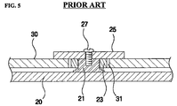
- FIG. 5 is a cross-sectional view taken along line B-B in FIG. 3 .
- the AV system having an existing monitor tilting apparatus includes a main body 10 that is built in a cartridge on the body of a car. On a front surface of the main body 10 is a monitor 15 , which is tiltable.
- a slide chassis 30 On the low-surface chassis 20 disposed at a lower end of the main body 10 is a slide chassis 30 , as depicted in FIG. 3 , through which the monitor 15 can move back and forth. At this time, a lower end of the monitor 15 is connected to a monitor mounting part 38 of the slide chassis 30 .
- a long hole 35 is formed on the slide chassis 30 back and forth, enabling a motor part 50 and a back-and-forth motion member 60 to be mounted on the low-surface chassis 20 .
- a support bar 21 is placed on the low-surface chassis around the hole 35 formed on the slide chassis 30 , and a main printed circuit board 11 is mounted on the support bar 21 , being inside out.
- the motor part 50 including a motor 53 and a worm 55 .
- the main printed circuit board 11 has a plurality of control means for the motor part 50 .
- the worm 55 of the motor part 50 is engaged (or meshed) with a wormwheel 61
- the wormwheel 61 is engaged with a wheel 63 .
- Shafts of the wheel 63 and the wormwheel 61 are mounted on the low-surface chassis 20 .
- the wheel 63 is again engaged with a rack gear part 37 of the slide chassis 30 .
- FIG. 5 there is a plurality of guide shafts 21 fixed on the right and left sides of the low-surface chassis, and guide rollers 23 are positioned centering around the guide shafts 21 . Also, long holes 31 are formed on the slide chassis 30 centering around the guide rollers 23 in such a manner that when the slide chassis 30 moves, the long holes 31 move back and forth with respect to the guide rollers 23 .
- the guide rollers 23 as their name implies, play as a guide for the slide chassis 30 .
- the motor part 50 and the back-and-forth motion member 60 are mounted on the lower side of the main printed circuit board 11 which is attached to the low-surface chassis 20 with the help of the support bar 21 , they are not visible to naked eyes, and thus it is pretty difficult to assemble them.
- an object of the present invention to provide a driving assembly of an audio/video system for a vehicle with improved assembability and productivity and less defects in products, in which diverse parts in a motor part, a back-and-forth motion member or a main printed circuit board are easily seen to naked eyes simply by separating a main chassis and a low-surface chassis, whereby any one can easily change or repair parts.
- Another object of the present invention is to provide a driving assembly of an audio/video system for a vehicle, in which a motor is more firmly fastened by means of a bracket that support the motor.
- Still another object of the present invention is to provide a driving assembly of an audio/video system for a vehicle having a reinforced slide chassis structure by reinforcing a relatively weak long hole area.
- a driving assembly of an AV system for a vehicle having a tiltable monitor disposed at a front surface of a main body of the AV system including: a low-surface chassis disposed at a lower end of the main body; and a slide chassis mounted on the low-surface chassis, moving a lower side of the monitor back and forth, wherein a back-and-forth motion member for moving a motor part and the slide chassis back and forth, using power provided by the motor part, is mounted on the low-surface chassis.
- a connecter is mounted on the motor part, and the connector is connected to a main printed circuit board and cable for controlling the motor.
- the main printed circuit board is attached to the main body.
- the motor part includes: a motor; a printed circuit board mounted with the connector, being attached to one end of the motor; and a worm attached to the other hand of the motor, for transferring power from the motor to the back-and-forth motion member.
- the back-and-forth motion member includes: a wormwheel to be engaged with the worm, and a wheel, one end thereof being engaged with the wormwheel and the other end thereof being engaged with a slide chassis.
- the relatively weak long hole area of the slide chassis can be reinforced and strengthened.
- FIG. 1 is a perspective view of a related art AV system with a monitor tilting apparatus
- FIG. 2 is a perspective view of the monitor in FIG. 1 , in which the monitor is being tilted;
- FIG. 3 is a perspective view of a low-surface chassis of FIG. 2 ;
- FIG. 4 is a cross-sectional view taken along line A-A in FIG. 3 ;
- FIG. 5 is a cross-sectional view taken along line B-B in FIG. 3 ;
- FIG. 6 is a perspective view of a driving assembly of an audio/video system for a vehicle according to a preferred embodiment of the present invention.
- FIG. 7 is an enlarged side view of a motor part and a back-and-forth member in FIG. 6 ;
- FIG. 8 is a cross-sectional view taken along line C-C in FIG. 7 .
- FIG. 6 is a perspective view of a driving assembly of an audio/video system for a vehicle according to a preferred embodiment of the present invention
- FIG. 7 is an enlarged side view of a motor part and a back-and-forth member in FIG. 6
- FIG. 8 is a cross-sectional view taken along line C-C in FIG. 7 .
- the driving assembly of an A/V system with a tiltable monitor disposed at a front surface of a main body includes a low-surface chassis 200 positioned at a lower end of the main chassis 100 , a slide chassis 300 attached to the low-surface chassis 200 , a motor part 500 positioned at the low-surface chassis 200 , and a back-and-forth motion member 600 for moving the slide chassis back and forth using power provided by the motor part 500 .
- the monitor (not shown) is disposed at the front surface of the main body 100 of the AV system, and a main printed circuit board 110 is housed in the main body 100 .
- FIG. 6 One thing to be aware of in FIG. 6 is that to show inside of the main body 100 , the front surface 100 a of the main body 100 is upside down in the drawing.
- the main printed circuit board 110 has diverse parts for controlling a motor part 500 , and a cable 130 connected to a connector 150 .
- a plurality of guide shafts 210 are fixed in the right and left sides of the low-surface chassis 200 .
- FIG. 8 illustrates, a fastening hole (not shown) to which a bolt 270 is inserted is formed on a top end of the respective guide shafts 210 , and guide rollers 230 for guiding the slide chassis 300 are installed, centering around the guide shafts 210 .
- slide chassis 300 On the slide chassis 300 is a long hole 310 to which guide rollers 230 are inserted, enabling the slide chassis 300 to move back and forth.
- guide rollers 230 of the guide shafts 210 fasted onto the low-surface chassis 200 are inserted to the long hole 310 of the slide chassis 300 , and thus, the guide shafts 210 are protruded to the long hole 310 .
- a washer 250 is mounted on the respective guide shafts 210 , to inhibit the guide roller 230 from derailing, and then the bolt 270 is inserted to the fastening hole of the guide shaft 210 .
- a “ ⁇ ”-shaped reinforcing bracket 390 is formed along the long hole 310 formed on the slide chassis 300 .
- This reinforcing bracket 390 is fastened onto the slide chassis by means of a plurality of fastening means 390 a , e.g. bolts.
- the reinforcing bracket 390 formed along the long hole 310 on the slide chassis 300 serves to reinforce and strengthen the long hole area that is a relatively weak portion of the slide chassis 200 .
- an assembly hole 391 is preferably drilled into a position on the reinforcing bracket 390 where guide shafts 210 are attached.
- Both ends of the slide chassis 300 are monitor mounting parts 380 on which the lower end of the monitor is placed.
- a long hole 350 is formed on a central portion of the slide chassis 300 in such a manner that the motor part 500 and the back-and-forth motion member 600 can be mounted on the low-surface chassis 200 .
- the motor part 500 includes a motor 530 , a printed circuit board 400 attached to one end of the motor 530 , and a worm 550 attached to the other end of the motor 530 , transferring power from the motor 530 to the back-and-forth motion member 600 .
- the printed circuit board 400 is fastened on the low-surface chassis 200 , and the motor 530 is attached to the printed circuit board 400 .
- One side of the printed circuit board 400 is a connecter 510 .
- the worm 500 is attached to a motor shaft 530 a , and it rotates as the motor 530 starts driving.
- bracket 410 attached to the motor 530 , to support the low surface of the motor 530 and the motor shaft 530 a . Thanks to this bracket 410 , the motor 530 is more firmly fastened on the printed circuit board 400 .
- the back-and-forth motion member 600 includes a wormwheel 610 , which is engaged with a worm 550 , and a wheel 630 , one end thereof being engaged with the wormwheel 610 and the other end being engaged with the slide chassis 300 .
- the wormwheel 610 constitutes a head 613 and a body 615 , each having gear teeth. And, a shaft at the center of the wormwheel 610 is mounted on the low-surface chassis 200 .
- the wheel Similar to the wormwheel 610 , the wheel also constitutes a head 633 and a body 635 , each having gear teeth. And, a shaft at the center of the wheel 630 is mounted on the low-surface chassis 200 .
- the head 633 of the wheel is engaged with the body 615 of the wormwheel 610 .
- the body 635 of the wheel is engaged with a rack gear part 370 that is formed on the slide chassis 300 in a direction of the slide chassis' motion.
- the connector 150 of a cable 130 of the main printed circuit board 110 fixed to the main chassis 100 is inserted to the connector 510 of the printed circuit board 400 fixed to the low-surface chassis 200 .
- the main chassis 100 and the low-surface chassis 200 are put together, and fastened to each other by a fastening means, e.g. bolt.
- a vehicle driver presses a switch to drive the motor part 500 .
- the wormwheel 610 of the motor 530 starts rotating, and the wormwheel 610 being perpendicularly meshed (or engaged) with the wheel 630 starts rotating. Since this wormwheel 610 is engaged with the wheel 630 , the wheel 630 also starts rotating. At this time, because the wheel 630 has a larger diameter than that of the wormwheel 610 , it plays as a reduction gear, reducing the speed.
- the rack gear part 370 of the slide chassis 300 being engaged with the wheel 630 makes a straight-line motion to the front, and thus, the slide chassis 300 moves forward.
- the motor shaft 530 rotates in a reverse direction
- the wormwheel 610 also rotates in a reverse direction of the above.
- the wormwheel 610 and the wheel 630 rotate in a reverse direction of the above, and the rack gear part 370 of the slide chassis 300 moves backward.
- the main chassis 100 is first separated from the low-surface chassis 200 , and the connector 150 of the main printed circuit board 110 is separated from the connector 510 of the printed circuit board 400 .
- the present invention unlike the related art, has better assembability because one can actually see the motor part 500 and the back-and-forth motion member 600 mounted on the low-surface chassis 200 when changing or repairing faulted parts.
- the driving assembly of the AV system of the present invention has the following advantages.
- the driving assembly of the AV system of the invention has better assembability. More specifically, according to the driving assembly of the invention, the motor part and the back-and-forth motion member for moving the slide chassis back and forth using power provided by the motor part are mounted on the low-surface chassis, and the connector attached to the motor part is connected to the main printed circuit board and the cable for controlling the motor. Hence, if there are faulted parts in the motor part or the back-and-forth motion member, or in other parts for controlling the motor part of the main printed circuit board, any one can easily identify and see the faulted parts to be changed or repaired, simply by separating the main chassis from the low-surface chassis.
- the relatively weak long hole area of the slide chassis can be reinforced and strengthened.
Abstract
Description
Claims (7)
Applications Claiming Priority (2)
| Application Number | Priority Date | Filing Date | Title |
|---|---|---|---|
| KR10-2003-0063543A KR100520991B1 (en) | 2003-09-15 | 2003-09-15 | driving assembly of audio/video system for a vehicle |
| KR10-2003-0063543 | 2003-09-15 |
Publications (2)
| Publication Number | Publication Date |
|---|---|
| US20050056733A1 US20050056733A1 (en) | 2005-03-17 |
| US7626642B2 true US7626642B2 (en) | 2009-12-01 |
Family
ID=34270698
Family Applications (1)
| Application Number | Title | Priority Date | Filing Date |
|---|---|---|---|
| US10/720,350 Active 2026-03-24 US7626642B2 (en) | 2003-09-15 | 2003-11-25 | Driving assembly of audio/video system for a vehicle |
Country Status (2)
| Country | Link |
|---|---|
| US (1) | US7626642B2 (en) |
| KR (1) | KR100520991B1 (en) |
Cited By (2)
| Publication number | Priority date | Publication date | Assignee | Title |
|---|---|---|---|---|
| US20090262507A1 (en) * | 2008-04-21 | 2009-10-22 | Fujitsu Limited | Electronic apparatus |
| US20100214760A1 (en) * | 2007-11-14 | 2010-08-26 | Fujikura Ltd. | Harness-integrated slide hinge and sliding-type electronic apparatus |
Families Citing this family (2)
| Publication number | Priority date | Publication date | Assignee | Title |
|---|---|---|---|---|
| KR100503310B1 (en) * | 2003-09-15 | 2005-07-25 | 현대모비스 주식회사 | reinforced slide chassis structure of audio/video system for a vehicle |
| US9222836B2 (en) * | 2012-11-01 | 2015-12-29 | Aaron James Conti | Hair colorant system and method |
Citations (12)
| Publication number | Priority date | Publication date | Assignee | Title |
|---|---|---|---|---|
| US2042002A (en) * | 1933-10-12 | 1936-05-26 | Budd Edward G Mfg Co | Flexible metallic closure |
| US4362108A (en) * | 1979-05-16 | 1982-12-07 | Erwin Jenkner | Conveyor system |
| US5762412A (en) * | 1995-12-28 | 1998-06-09 | Daewoo Electronics Co., Ltd. | Panel opening and closing apparatus |
| US5845897A (en) | 1996-04-25 | 1998-12-08 | Tunkers Maschinenbau Gmbh | Toggle lever clamp device for automobile body fabrication |
| US5850215A (en) * | 1995-03-20 | 1998-12-15 | Aisin Aw Co., Ltd. | Display apparatus for a car |
| US5912541A (en) * | 1994-11-30 | 1999-06-15 | Bigler; Robert A. | Integrated DC servo motor and controller |
| US5941615A (en) * | 1996-10-23 | 1999-08-24 | Harness System Technologies Research, Ltd. | Movable structure for a display |
| KR20000011042A (en) | 1996-05-14 | 2000-02-25 | 프랭크 제이. 윌리엄 삼세 | Air freshener dispenser device |
| US20020005897A1 (en) | 2000-07-11 | 2002-01-17 | Kim Kyung Wook | Apparatus for controlling angle of AV front panel for automobile |
| US6731350B2 (en) * | 2000-04-20 | 2004-05-04 | Alpine Electronics, Inc. | Vehicle-mounted display system |
| US7137676B2 (en) * | 2001-11-08 | 2006-11-21 | Pioneer Corporation | Electronic appliance |
| US7224579B2 (en) * | 2003-09-15 | 2007-05-29 | Hyundai Autonet Co., Ltd. | Reinforced slide chassis structure of audio/video system for a vehicle |
-
2003
- 2003-09-15 KR KR10-2003-0063543A patent/KR100520991B1/en not_active IP Right Cessation
- 2003-11-25 US US10/720,350 patent/US7626642B2/en active Active
Patent Citations (14)
| Publication number | Priority date | Publication date | Assignee | Title |
|---|---|---|---|---|
| US2042002A (en) * | 1933-10-12 | 1936-05-26 | Budd Edward G Mfg Co | Flexible metallic closure |
| US4362108A (en) * | 1979-05-16 | 1982-12-07 | Erwin Jenkner | Conveyor system |
| US5912541C1 (en) * | 1994-11-30 | 2002-06-11 | Animatics Corp | Integrated servo motor and controller |
| US5912541A (en) * | 1994-11-30 | 1999-06-15 | Bigler; Robert A. | Integrated DC servo motor and controller |
| US5850215A (en) * | 1995-03-20 | 1998-12-15 | Aisin Aw Co., Ltd. | Display apparatus for a car |
| US5762412A (en) * | 1995-12-28 | 1998-06-09 | Daewoo Electronics Co., Ltd. | Panel opening and closing apparatus |
| US5845897A (en) | 1996-04-25 | 1998-12-08 | Tunkers Maschinenbau Gmbh | Toggle lever clamp device for automobile body fabrication |
| KR20000011042A (en) | 1996-05-14 | 2000-02-25 | 프랭크 제이. 윌리엄 삼세 | Air freshener dispenser device |
| US5941615A (en) * | 1996-10-23 | 1999-08-24 | Harness System Technologies Research, Ltd. | Movable structure for a display |
| US6731350B2 (en) * | 2000-04-20 | 2004-05-04 | Alpine Electronics, Inc. | Vehicle-mounted display system |
| KR20020006075A (en) | 2000-07-11 | 2002-01-19 | 윤장진 | An angle controlling appartus of AV front pannel for automobile |
| US20020005897A1 (en) | 2000-07-11 | 2002-01-17 | Kim Kyung Wook | Apparatus for controlling angle of AV front panel for automobile |
| US7137676B2 (en) * | 2001-11-08 | 2006-11-21 | Pioneer Corporation | Electronic appliance |
| US7224579B2 (en) * | 2003-09-15 | 2007-05-29 | Hyundai Autonet Co., Ltd. | Reinforced slide chassis structure of audio/video system for a vehicle |
Cited By (4)
| Publication number | Priority date | Publication date | Assignee | Title |
|---|---|---|---|---|
| US20100214760A1 (en) * | 2007-11-14 | 2010-08-26 | Fujikura Ltd. | Harness-integrated slide hinge and sliding-type electronic apparatus |
| US8169794B2 (en) * | 2007-11-14 | 2012-05-01 | Fujikura Ltd. | Harness-integrated slide hinge and sliding-type electronic apparatus |
| US20090262507A1 (en) * | 2008-04-21 | 2009-10-22 | Fujitsu Limited | Electronic apparatus |
| US7881073B2 (en) * | 2008-04-21 | 2011-02-01 | Fujitsu Limited | Electronic apparatus |
Also Published As
| Publication number | Publication date |
|---|---|
| KR100520991B1 (en) | 2005-10-11 |
| US20050056733A1 (en) | 2005-03-17 |
| KR20050027317A (en) | 2005-03-21 |
Similar Documents
| Publication | Publication Date | Title |
|---|---|---|
| US7224579B2 (en) | Reinforced slide chassis structure of audio/video system for a vehicle | |
| US7626642B2 (en) | Driving assembly of audio/video system for a vehicle | |
| CN103552516A (en) | Manually or electrically overturnable vehicle-mounted display screen | |
| US7090232B2 (en) | Steering knuckle assembly for vehicles | |
| CN100358751C (en) | Vehicle mounted GPS navigation, image and sound system terminal display screen and panel control device thereof | |
| JP2002356132A (en) | On-vehicle large-sized screen display device and vehicle mounted with the device | |
| JPH11278167A (en) | Car-mounting image display unit | |
| KR100567255B1 (en) | structure to prevent from deforming shaft of gear train of driving assembly of audio/video system for a vehicle | |
| KR20040088674A (en) | Display apparatus for a vehicle | |
| KR100402218B1 (en) | Car television of roof mounted type | |
| CN212500173U (en) | Display screen mounting bracket for vehicle | |
| KR200246618Y1 (en) | Car television of roof mounted type | |
| JPH11151987A (en) | Attachment for car navigation system | |
| CN217753652U (en) | Turnover type vehicle-mounted display | |
| JP3202635B2 (en) | Power slide device for automobile seats | |
| KR200320213Y1 (en) | Apparatus for automatically receving monitor for vehicles | |
| CN1704286A (en) | Vehicle mounted GPS navigation, image and sound system display screen and panel control device thereof | |
| KR100847495B1 (en) | Supporter for indash type of vehicle | |
| JP3191916B2 (en) | Order picker car wheel indicator | |
| JP2000228082A (en) | Electronic apparatus with moving member | |
| KR960007808Y1 (en) | Steering angle displayer of front wheels | |
| KR100193432B1 (en) | Combined device of control base for automatic navigation device | |
| KR100706405B1 (en) | Structure of the monitor which is in the vehicle | |
| KR100600105B1 (en) | Monitor for automobile | |
| KR200142684Y1 (en) | Front loading apparatus of audio/video systems for a car |
Legal Events
| Date | Code | Title | Description |
|---|---|---|---|
| AS | Assignment |
Owner name: HYUNDAI MOBIS, CO., LTD., KOREA, REPUBLIC OF Free format text: ASSIGNMENT OF ASSIGNORS INTEREST;ASSIGNOR:LEE, SANG-HO;REEL/FRAME:014741/0882 Effective date: 20031113 |
|
| AS | Assignment |
Owner name: HYUNDAI AUTONET CO., LTD., KOREA, REPUBLIC OF Free format text: ASSIGNMENT OF ASSIGNORS INTEREST;ASSIGNOR:HYUNDAI MOBIS CO., LTD.;REEL/FRAME:017622/0660 Effective date: 20060509 |
|
| STCF | Information on status: patent grant |
Free format text: PATENTED CASE |
|
| FEPP | Fee payment procedure |
Free format text: PAYOR NUMBER ASSIGNED (ORIGINAL EVENT CODE: ASPN); ENTITY STATUS OF PATENT OWNER: LARGE ENTITY Free format text: PAYER NUMBER DE-ASSIGNED (ORIGINAL EVENT CODE: RMPN); ENTITY STATUS OF PATENT OWNER: LARGE ENTITY |
|
| FEPP | Fee payment procedure |
Free format text: PAYOR NUMBER ASSIGNED (ORIGINAL EVENT CODE: ASPN); ENTITY STATUS OF PATENT OWNER: LARGE ENTITY Free format text: PAYER NUMBER DE-ASSIGNED (ORIGINAL EVENT CODE: RMPN); ENTITY STATUS OF PATENT OWNER: LARGE ENTITY |
|
| FPAY | Fee payment |
Year of fee payment: 4 |
|
| FPAY | Fee payment |
Year of fee payment: 8 |
|
| MAFP | Maintenance fee payment |
Free format text: PAYMENT OF MAINTENANCE FEE, 12TH YEAR, LARGE ENTITY (ORIGINAL EVENT CODE: M1553); ENTITY STATUS OF PATENT OWNER: LARGE ENTITY Year of fee payment: 12 |