US7623536B2 - Network relaying method and device - Google Patents
Network relaying method and device Download PDFInfo
- Publication number
- US7623536B2 US7623536B2 US11/097,709 US9770905A US7623536B2 US 7623536 B2 US7623536 B2 US 7623536B2 US 9770905 A US9770905 A US 9770905A US 7623536 B2 US7623536 B2 US 7623536B2
- Authority
- US
- United States
- Prior art keywords
- leave
- join
- multicast
- information
- client
- Prior art date
- Legal status (The legal status is an assumption and is not a legal conclusion. Google has not performed a legal analysis and makes no representation as to the accuracy of the status listed.)
- Expired - Fee Related, expires
Links
Images


Classifications
-
- H—ELECTRICITY
- H04—ELECTRIC COMMUNICATION TECHNIQUE
- H04L—TRANSMISSION OF DIGITAL INFORMATION, e.g. TELEGRAPHIC COMMUNICATION
- H04L12/00—Data switching networks
- H04L12/02—Details
- H04L12/16—Arrangements for providing special services to substations
- H04L12/18—Arrangements for providing special services to substations for broadcast or conference, e.g. multicast
- H04L12/185—Arrangements for providing special services to substations for broadcast or conference, e.g. multicast with management of multicast group membership
Definitions
- the present invention relates to a network relaying method and device, and in particular to a network relaying method and device at the time of distributing data from a server to a client by multicast.
- the multicast can not perform an on-demand distribution basically, it has numerous merits in a real-time moving image distribution and voice distribution such as live broadcasting.
- a server S 1 can make numerous clients R 1 , R 2 , . . . receive data through multicast routers 1 _ 1 and 1 _ 2 (hereinafter, occasionally represented by a reference numeral “ 1 ”) and LAN switches SW 1 , SW 2 (hereinafter, occasionally represented by a reference numeral “SW”) only by transmitting a single stream to a multicast-capable network MNW, regardless of the number of users (clients) who receive the data.
- multicast routers 1 _ 1 and 1 _ 2 hereinafter, occasionally represented by a reference numeral “ 1 ”
- SW LAN switches
- a traffic amount of a certain path can be kept fixed regardless of the number of users, little influence is exerted on other communications, and facilities such as a network and a cache server specific to a distribution are not required different from the case of the unicast, so that it becomes possible to distribute the multimedia data very inexpensively.
- IP multicast address group address
- IGMP Internet Group Management Protocol
- An IP multicast distribution uses the multicast address, functions between clients R 1 , R 2 and a multicast router 1 as shown in FIGS. 28A and 28B , and is realized by operating the IGMP, which provides a function that the router 1 grasps the multicast group of the subordinate clients R 1 and R 2 and the multicast routing protocol which constructs a multicast data distribution tree from the server to a plurality of receiving clients between routers.
- the IGMP is a protocol with which the router 1 grasps/manages whether or not a receiving client exists in a local network to which the router itself belongs by transferring an IGMP message of a packet format shown in FIG. 29 between the clients R 1 , R 2 and the router 1 .
- the IGMP is a protocol between the router and the client for informing the router 1 that the clients R 1 and R 2 join a certain multicast group. Both of the router and the clients are required to mount a function specified by the IGMP (applied when a “protocol ID” in an IP header shown in FIG. 30 is “2”).
- An IGMPv1 is specified in an appendix 1 of RFC 1112
- an IGMPv2 is specified in RFC 2236
- an IGMPv3 is being standardized in IETF.
- the multicast routing protocol is a protocol between routers for a path control (or arrangement of a path tree) determining to which interface of the router 1 multicast data are copied in order for the router 1 to distribute a multicast data stream to the receiving clients R 1 and R 2 in a network composed of a plurality of multicast routers 1 and the layer 3 switches SW as shown in FIG. 1 .
- DVMRP used in MBone, specified in RFC 1075
- PIM specified in RFC 2117; new version IETF is being reviewed
- MOSPF operable only on OSFP, specified in RFC 1584 and 1585
- the above-mentioned RFC 1112 has a function of mapping between an IP address of a class D, i.e. a multicast IP address and a multicast physical address, and a filtering function of receiving only a packet of a specific multicast physical address and of transferring the packet to an upper layer.
- a correspondence between the multicast IP address and the multicast physical address is specified (in RFC 1700) to put lower 23 bits of the multicast IP address into the lower 23 bits of the multicast physical address “01.00.5E.00.00.00 16 ”.
- the multicast IP address “239.133.130.34” is the multicast physical address “01:00:5E:05:82:22”.
- IPv4 is specified as a class D address, in a range from “224.0.0.0” to “239.259.255.255” by a decimal notation.
- FIG. 31 shows the IP address of the class D.
- the class D address is identified with the first 4 bits “1110”. As shown in FIG. 31 , some multicast addresses are reserved for specific usages.
- IP multicast addresses generally used by e.g. an enterprise network, an ISP, and the like.
- FIGS. 28A and 28B A distribution procedure of the above-mentioned multicast data will now be simply described by referring to FIGS. 28A and 28B .
- the multicast router 1 In order to query the clients R 1 and R 2 connected to the local network as to a join to a multicast group, the multicast router 1 periodically transmits to “224.0.0.1” (All-Systems-Group) an “HMQ (Host Membership Query)” message (see ⁇ circle around ( 1 ) ⁇ in FIG. 28A ) in which a type value is “0x11” within an IGMP header of a packet in a format (IGMPv2) shown in FIG. 29 .
- HMQ Home Membership Query
- the client transmits an “HMR (Host Membership Report)” message (see ⁇ circle around ( 2 ) ⁇ in FIG. 28A ) whose type value is “0x12” within the IGMP header of the packet in the same format to the multicast address which the client joins.
- HMR Home Membership Report
- the multicast router 1 grasps the multicast group (identified by the above-mentioned class D address) which the client joins, and starts the transmission of multicast data (stream) to the local network.
- a transmitting server such as the server S 1 in FIG. 1 of the multicast data transmits “single” data (stream) to the multicast group identified with the class D address.
- the multicast router 1 within the network copies the data stream addressed to the group as required to be transmitted along the path to each receiving client which joins the multicast group.
- the multicast data are distributed along the path tree, formed by a multicast routing protocol, of the multicast data distribution from the transmitting server to each receiving client.
- the “single” data stream transmitted by the server is distributed to “a plurality of” clients within the network.
- the multicast router 1 In order to confirm that there is no other client which has joined the multicast group, the multicast router 1 having received the “leave” message transmits a “GS-Q (Group Specific Query)” message (see ⁇ circle around ( 4 ) ⁇ in FIG. 28B ) by designating the group address.
- GS-Q Group Specific Query
- the other client transmits the “HMR” message to inform its existence to the multicast router 1 .
- the difficulty of the management means that it is impossible to grasp e.g. the number of receiving clients at a certain time, and how long (from when until when) each client has received data, and to acquire and manage information of the client itself.
- a network relaying method comprises: a first step of discriminating join/leave information transmitted by a client to a multicast group; a second step of processing the join/leave information of the client into multicast join/leave notifying information; and a third step of transferring the multicast join/leave notifying information to a server.
- the above-mentioned multicast join/leave notifying information may include identifying information of the client, a multicast address and a join/leave starting time.
- the above-mentioned first step may discriminate the join/leave information of the client mounted on a multicast control packet from the client, the second step may process the join/leave information of the client into the multicast join/leave notifying packet and the third step may transfer the multicast join/leave notifying packet to the server.
- the above-mentioned second step may generate an aggregated join/leave notifying packet in which the join/leave information for all of the clients is aggregated in a single packet and the third step may transfer the aggregated join/leave notifying packet to the server.
- the above-mentioned third step may further transfer the multicast join/leave notifying packet to the server.
- the third step may further transfer the aggregated join/leave notifying packet to the server.
- the above-mentioned second step may generate, when the join/leave information for a same multicast group from the client itself is aggregated, an aggregated join/leave notifying packet in which all of join/leave information is aggregated in a single packet and the third step may immediately transfer the aggregated join/leave notifying packet to the server.
- the above-mentioned third step may hold the join/leave information of the client until a transfer is requested from the server.
- a transmitting source address included in a packet may be used as identifying information of the above-mentioned client.
- the third step may transmit leave notifying information of the client to the server.
- a network relaying device for realizing the network relaying method according to the present invention comprises: a discriminating portion for discriminating join/leave information transmitted by a client to a multicast group; an information processing portion for processing the join/leave information of the client into multicast join/leave notifying information; and a transfer processor for transferring the multicast join/leave notifying information to a server.
- the above-mentioned multicast join/leave notifying information may include identifying information of the client, a multicast address and a join/leave starting time.
- the above-mentioned discriminating portion may discriminate the join/leave information of the client mounted on a multicast control packet from the client, the information processing portion may process the join/leave information of the client into the multicast join/leave notifying packet and the transfer processor may transfer the multicast join/leave notifying packet to the server.
- the above-mentioned information processing portion may generate an aggregated join/leave notifying packet in which the join/leave information for all of the clients is aggregated in a single packet and the transfer processor may transfer the aggregated join/leave notifying packet to the server.
- the above-mentioned transfer processor may further transfer the multicast join/leave notifying packet to the server.
- the above-mentioned transfer processor may further transfer the aggregated join/leave notifying packet to the server.
- the above-mentioned information processing portion may generate, when the join/leave information for a same multicast group from the client itself is aggregated, an aggregated join/leave notifying packet in which all of join/leave information is aggregated in a single packet and the transfer processor may immediately transfer the aggregated join/leave notifying packet to the server.
- the above-mentioned transfer processor may hold the join/leave information of the client until a transfer is requested from the server.
- a transmitting source address included in a packet may be used as identifying information of the above-mentioned client.
- the above-mentioned transfer processor may transmit leave notifying information of the client to the server.
- a server may comprise: a discriminating portion for discriminating multicast join/leave notifying information transmitted from the above-mentioned network relay; and a holding portion for extracting information of the client in the multicast join/leave notifying information to be held.
- the server may further comprise means charging by the hour a multicast data distribution (content reception) based on the client information.
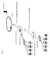
- FIG. 1 shows a network arrangement for illustrating a concept of the present invention.
- S 1 denotes a transmitting server of multicast data
- 1 _ 1 and 1 _ 2 denote multicast (-capable) routers in which the network relaying method and device of the present invention are mounted
- SW 1 and SW 2 denote LAN switches or layer 2 switches accommodating clients
- MNW denotes a network composed of the multicast routers
- R 1 denotes a client which receives normal data
- R 2 denotes a client which receives multicast data
- PKT 1 denotes a multicast control packet which functions between the receiving clients R 1 , R 2 and the multicast router 1 _ 2
- PKT 2 denotes a user information packet including join or leave (hereinafter, referred to as join/leave) information of the receiving clients and being transferred to the server S 1 .
- the packets PKT 1 and PKT 2 are occasionally represented by a reference numeral PKT.
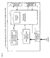
- FIG. 2 shows a diagram of a principle arrangement of a network relaying device 1 of the present invention which is a router in which a normal multicast function is mounted.
- the network relaying device 1 is composed of transmitting/receiving interfaces 2 , 7 and 8 , a discriminating portion 3 of the multicast control packet PKT 1 , a generator 4 of a client management information packet PKT 2 for notifying the user information to the server S 1 , and a transfer processor 5 which includes a routing table 6 and which performs routing processing (including multicast routing processing) or the like mounted on the normal network relay.
- the multicast control packet PKT 1 for notifying the multicast router 1 that the receiving client desires to receive the multicast data (desires to join multicast group) or stops receiving the multicast data although the data having been received (desires to leave multicast group) is transmitted from the receiving client R 2 , and the multicast router 1 receives this packet.
- the multicast router 1 examines what the received packet is by the packet discriminating portion 3 . If the packet is a multicast control packet PKT 1 , it is transferred to the transfer processor 5 for performing a normal multicast data transfer control, so that the information is reflected on the routing table 6 .
- the packet generator 4 in order to manage the user information in the server S 1 , the packet generator 4 generates the multicast join/leave notifying packet storing the user information to be transferred to the transfer processor 5 , so that it is transferred from an interface 7 or 8 in the direction where the server S 1 exists.
- the packet reaches the server S 1 , thereby enabling a reception user management of data which has been difficult by the prior art multicast data transfer to be realized.
- FIG. 1 is a diagram showing a network arrangement for illustrating a network relaying method and device according to the present invention
- FIG. 2 is a block diagram of a principle arrangement of a network relaying device according to the present invention.
- FIG. 3 is a diagram showing a network arrangement for illustrating an embodiment of the present invention.
- FIG. 4 is a diagram showing a simplified network arrangement of the network arrangement of FIG. 3 ;
- FIG. 5 is a block diagram showing an arrangement of an embodiment of a network relaying device according to the present invention.
- FIG. 6 is a format diagram of a multicast join notifying packet
- FIGS. 7A and 7B are diagrams showing a multicast join notifying sequence to a server and a receiving client management table managed by the server;
- FIG. 8 is a diagram showing a network example at the time of aggregating client information
- FIG. 9 is a format diagram of a multicast aggregated join notifying packet
- FIGS. 10A and 10B are diagrams showing a multicast aggregated join notifying sequence to a server and a receiving client management table
- FIG. 11 is a diagram showing an aggregated network example of a multicast aggregated join notifying packet from a downstream direction and a multicast join desiring message information;
- FIG. 12 is a format diagram of a multicast aggregated join notifying packet to which information is added on the way to a server;
- FIGS. 13A and 13B are diagrams showing an information addition sequence to a multicast aggregated join notifying packet and a receiving client management table
- FIG. 14 is a block diagram showing an embodiment of a server (serving as client management server and multicast data transmitting server);
- FIG. 15 is a format diagram of a multicast (aggregated) join notifying packet identified with a protocol ID field
- FIG. 16 is a format diagram showing an IP header in FIG. 15 ;
- FIG. 17 is a format diagram of a multicast leave notifying packet
- FIGS. 18A and 18B are diagrams showing a multicast leave notifying sequence to a server and a receiving client management table
- FIG. 19 is a format diagram of a multicast aggregated leave notifying packet
- FIG. 20 is a diagram of a receiving client management table managed by a server at the time of leaving multicast aggregation
- FIG. 21 is a format diagram of a multicast aggregated leave notifying packet to which information is added on the way to a server;
- FIG. 22 is a diagram of a receiving client management table managed by the server concerning FIG. 21 ;
- FIG. 23 is a general format diagram of an ICMPv6 message
- FIG. 24 is a general format diagram of an MLD message
- FIGS. 25A and 25B are diagrams showing a summary of a detection of a client fault, a server notification, and a management table update
- FIG. 26 is a concept diagram of charging service in accordance with time when a multicast content is used.
- FIG. 27 is a diagram showing an example of multicast content distribution service and a time charging system using the present invention.
- FIGS. 28A and 28B are diagrams for illustrating a general multicast join/leave procedure of an IGMP
- FIG. 29 is a general format diagram of an IGMPv2 packet
- FIG. 30 is a general format diagram of an IPv4 header
- FIG. 31 is a diagram illustrating an assignment according to a usage purpose of a multicast address.
- IGMPv2 (specified in RFC 2236) message which has the most widely spread and has been mounted will now be described.
- the present invention can be also applied to a case where the multicast control message is of the IGMPv1 or IGMPv3.
- the function corresponding to the IGMPv2 is called an MLD (Multicast Listener Discovery), and specified in RFC 2710. Also, the function corresponding to the IGMPv3 is being standardized by IETF. While the case where the network layer is of IPv4 will, be described in this embodiment, this embodiment can be also applied to the case of the IPv6, as a matter of course. The difference between the IPv6 multicast and the IPv4 multicast will be described later.
- FIG. 3 shows a general IP network such as an enterprise IP network, an IP network of an ISP (Internet Service Provider) and a carrier which are targets of the present invention.
- the IP network is composed of clients R 1 -R 3 such as personal computers, multicast-capable routers 1 _ 1 - 1 _ 8 (hereinafter, occasionally represented by a reference numeral “ 1 ”) which compose a network, a server S 1 which distributes and manages multicast data by a multicast routing protocol MRP and the like.
- a form in which the clients R 1 -R 3 are accommodated in the LAN switch/layer 2 switch to be connected to the multicast router 1 is general in an enterprise and accesses over the Internet. However, this form is not shown for simplifying the figure. It is to be noted that client management information packets CMP 1 -CMP 3 in FIG. 3 are respectively composed of the packets PKT 1 and PKT 2 of FIG. 1 .
- FIG. 4 shows a simplified embodiment [1] of the present invention in the network arrangement of FIG. 3 .
- FIG. 4 shows a state where the multicast join packet PKT 1 is transmitted to the multicast router 1 from the client R 1 , a multicast join notifying packet PKT 2 _ 1 is transmitted from the multicast router 1 to the server S 1 in response to the packet PKT 1 , and a state where the server S 1 transmits multicast data DT.
- the IGMP packet format and the IGMP message field are the same as those shown in FIG. 29 , and the IPv4 header shown in FIG. 30 may be used for the IPv4 header.
- FIG. 5 shows an arrangement of an embodiment such as a multicast router, a multicast-capable layer 3 switch of the network relay, whose principle is shown in FIG. 2 , according to the present invention.
- packet discriminating portions 3 _ 1 - 3 _ 3 detect a multicast join desiring message (IGMP Report) and a leave desiring message (IGMP Leave message) from a client to be transmitted to not only a multicast processor 9 which performs a known multicast control but also a timer 10 and a client information holding portion 11 .
- the timer 10 is used when a join/leave information notifying message (packet) in which client information is aggregated is generated together with the client information holding portion 11 and the packet generator 4 described later.
- the network relaying device 1 grasps the information of the receiving clients R 1 -R 3 of the multicast data existing in the subordinate of its own interfaces 2 , 7 , and 8 . Specifically, the packets transmitted from the clients R 1 -R 3 desiring the reception of the multicast data are examined by the packet discriminating portion 3 . If the packets include the IGMP reports (join desiring messages), it is recognized that the receiving client exists in the subordinate of the receiving interface.
- IGMP reports join desiring messages
- ⁇ circle around (1) ⁇ an IP address is a multicast address
- the ⁇ circle around (2) ⁇ “protocol No.” within the IP header is “2” indicating the IGMP
- ⁇ circle around (3) ⁇ the type value of the IGMP message is “0x16” are firstly confirmed.
- the multicast address (group address) which the receiving clients R 1 -R 3 desire to receive is stored in the IGMP report.
- the network relaying device 1 generates the multicast join notifying packet PKT 2 _ 1 with the destination address (see FIG. 30 ) as an address of the server S 1 at the packet generator 4 so that the server S 1 may manage that the client of transmitting source of the message desires to receive the multicast data (desire to join multicast). Then, the transfer processor 5 transfers the multicast join notifying packet PKT 2 _ 1 to the server S 1 by normal routing processing.
- the type value of the IGMP message is changed to be transmitted so that the server S 1 may identify the multicast join notifying message when the server S 1 receives the packet.
- the type value of the IGMP message determined by the standard there are a version 1 (IGMPv1), a version 2 (IGMPv2) and a version 3 (IGMPv3) (being standardized by IETF (Internet Engineering Task Force) which is a standardization group of the Internet technology).
- IGMPv1 version 1
- IGMPv2 version 2
- IGMPv3 version 3
- IETF Internet Engineering Task Force
- the IGMP report indicating that the clients R 1 -R 3 desire to receive multicast data DT 1 -DT 3 is transmitted to an address which the clients R 1 -R 3 desire to receive (in the IGMPv3 under review, it is transmitted to “224.0.0.22”).
- the network relaying device 1 when receiving the IGMP report, replaces its destination address field by the server address to be transmitted to the server S 1 .
- a multicast address G 1 which the client desires to receive is included in the group address.
- the addresses can be independently managed.
- FIG. 6 shows a format of the multicast join notifying packet PKT 2 _ 1 transmitted from the network relaying device 1 to the server S 1 as mentioned above.
- the address of the client R 1 desiring the multicast join and a join starting time t 1 are mounted.
- the server S 1 having received this packet confirms the message type.
- the address of the client R 1 stored in the source address field is associated with the address G 1 of the multicast data transmitted by the server S 1 and the reception time t 1 of the join notifying packet to be stored.
- the client R 1 can manage which multicast data (G 1 in this example) has been received and when (t 1 in this example) the data reception has started.
- the network relaying device 1 accommodating the receiving client R 1 in its own interface can not recognize the multicast address G 1 and the address of the server S 1 until the multicast data are received.
- the network relaying device 1 can recognize the relationship between the multicast address G 1 and its server S 1 , and can grasp the relationship between G 1 and S 1 when the IGMP report is received from the client R 1 , so that the information R 1 and G 1 can be transmitted to the server S 1 .
- the session of the multicast is distinguished by the multicast address. Therefore, if the IGMP report for e.g. a multicast address G 2 except G 1 is received, the processing is performed to G 2 in parallel with G 1 .
- FIG. 7A shows the above-mentioned operation sequence.
- the multicast router 1 When the IGMP report packet PKT 1 is transmitted from the client R 1 (see ( 1 ) in FIG. 7A ), the multicast router 1 having received the packet PKT 1 generates the multicast join notifying packet PKT 2 _ 1 (see ( 2 ) in FIG. 7A ).
- the packet PKT 2 _ 1 is further transmitted to the server S 1 through the multicast-capable network MNW (see ( 3 ) in FIG. 7A ), and a table for managing clients is prepared at the server S 1 (see ( 4 ) in FIG. 7A ).
- FIG. 7B shows an example of the table at this time.
- the network relaying device usually has a plurality of interfaces 2 , 8 and 7 as shown in FIG. 5 .
- the subnet is connected to each of the interfaces as shown in FIG. 8 , and numerous clients are connected to each subnet.
- numerous join notifying messages PKT 2 are to be transmitted to the server S 1 , which makes no problem if transmitted in a distributed manner, but which imposes processing load on the server S 1 if transmitted in a concentrated manner.
- each network relaying device 1 collects the information of the subordinate receiving clients and information of a plurality of clients is included in a single packet to be transmitted collectively.
- the network relaying device 1 receives a reception request control message, i.e. the IGMP report for the multicast address G 1 , the timer 10 is operated.
- the timer value when e.g. a server or an administrator who transmits multicast data or the like desires to manage information per minute for the purpose of charging, the timer value may be set with 60 sec.
- FIG. 10A shows a schematic operation sequence among the clients R 1 -R 3 , the multicast router 1 and the server S 1 .
- the multicast router 1 When the IGMP report packet is transmitted from the client R 1 (see ( 1 ) in FIG. 10A ), the multicast router 1 having received the packet starts up the timer 10 (see ( 2 ) in FIG. 10A ). After that, when the similar packets are received from the clients R 3 and R 2 (see ( 3 ) and ( 4 ) in FIG. 10A ), the aggregated join notifying packet is generated (see ( 6 ) in FIG. 10A ) on the condition that the timer 10 has expired (see ( 5 ) in FIG. 10A ), and the packet is transmitted to the server S 1 (see ( 7 ) in FIG. 10A ). The server S 1 prepares the management table of the client in response to the packet (see ( 8 ) in FIG. 10A ).
- FIG. 10B shows an example of an information table held by the server S 1 at this time. It is to be noted that “xx” and “tx” in FIG. 10B indicate a state in which a status concerning other multicasts and clients is possessed.
- the network relaying device 1 _ 1 also has the receiving client on a local interface at this time in the same way as the network relaying device 1 _ 2 .
- the network relaying device 1 _ 1 receives the join desiring message concerning multicast data G 1 from receiving clients R 11 -R 14 , and receives the aggregated join notifying packet PKT 2 _ 21 concerning the multicast data G 1 from the network relaying device 1 _ 2 in a state where the timer 10 is operated for collecting information, the network relaying device 1 _ 1 cancels the timer 10 in order to avoid delaying the information of the network relaying device 1 _ 2 and being delivered to the server S 1 .
- the network relaying device 1 _ 1 generates a packet PKT 2 _ 22 in which the information of the local receiving clients R 11 -R 14 which the network relaying device 1 _ 1 has held for the multicast data G 1 is added to the received aggregated join notifying packet PKT 2 _ 21 , and immediately transmits the packet PKT 2 _ 22 .
- FIG. 12 shows a format of the aggregated join notifying packet PKT 2 _ 22 transmitted from the network relaying device 1 _ 1 .
- the network relaying device 1 _ 1 transfers the packet to the interface in the direction of server as it is. Also, the operation is independently performed for every multicast address.
- FIG. 13A shows a sequence at this time.
- the timer is started up (see ( 2 ) in FIG. 13A ).
- the network relaying device 1 _ 1 receives the aggregated join notifying packet from the network relaying device 1 _ 2 (see ( 4 ) in FIG. 13A ) after receiving the multicast join packet from the client R 12 (see ( 3 ) in FIG. 13A ) after receiving the multicast join packet from the client R 12 (see ( 3 ) in FIG. 13A )
- the timer is compulsorily ended (see ( 5 ) in FIG.
- FIG. 13B shows an example of a table managed by the server S 1 at this time.
- the server also has a packet discriminating portion 22 for examining/identifying a user information packet.
- the packet is the user information packet
- client information, a status, and a reception starting time e.g. per minute are recorded in a client management table 23 .
- a management application 24 can grasp the number of users and information for calculating a charge in accordance with time. Also, when the number of users is large, the information can be made reference information for designing a server site such as an addition of a server having e.g. the same contents.
- FIG. 14 shows a case where the server also performs a receiver management and also a transmission of the multicast data. Also, a communication process 25 and an application 26 drive a multicast transmission controller 27 , and perform a function of transmitting the multicast data DT from the contents 28 to the multicast-capable network through a transmitting/receiving interface 21 .
- the multicast join notifying packet and the aggregated join notifying packet as shown in FIGS. 9 and 12 , a method of using the IGMP report received from the client for a necessary information transmission may be adopted, or the packets may be IP packets having an original format.
- multicast data address information may be included in a payload portion for a data link layer header (e.g. MAC header) and an IP header.
- a data link layer header e.g. MAC header
- IP header e.g. IP header
- a presently not specified value is used for the protocol ID of the IP header, and by confirming the value, the packet can be identified.
- protocol ID is managed by IANA (Internet Assigned Numbers Authority) or ICANN (The Internet Corporation for Assigned Names and Numbers)
- IANA Internet Assigned Numbers Authority
- ICANN The Internet Corporation for Assigned Names and Numbers
- the protocol ID can be used for an actual operation if a protocol ID for message is applied.
- a normal leave desiring message (packet), i.e. “IGMP Leave” is transmitted.
- the IGMP leave message is used, and in the IGMPv3, the IGMP report (transmitted to “224.0.0.22” indicating ALL-IGMPv3 router) in which the multicast address desiring reception is made “empty” is used.
- the leave message transmitted by the client which has received the multicast data is transmitted to “224.0.0.2” which is “All-Routers-Group address” (It is to be noted that the IGMP report of the IGMPv3 in which a multicast address desiring a reception is made “empty” is transmitted to “224.0.0.22”).
- the network relaying device 1 having received the leave message examines whether or not the message is the IGMP leave message by the packet discriminating portion 3 .
- the identification method of the IGMP leave message is firstly to confirm ⁇ circle around (1) ⁇ IP address is “224.0.0.2”, ⁇ circle around (2) ⁇ the “protocol No.” within the IP header is “2” indicating the IGMP, and ⁇ circle around (3) ⁇ the type value of the IGMP message is “0x17”.
- a multicast address which a receiving client desires to leave is similarly stored in the IGMP leave message.
- the packet generator 4 In order to inform to the server S 1 that the transmitting source client of the message desires to stop the reception of the multicast data which have been received, the packet generator 4 generates a leave notifying packet which has the address of the server S 1 as a destination address, and the transfer processor 5 transfers the packet to the server S 1 by general routing processing.
- FIG. 17 shows a format example of such a leave notifying packet.
- the server S 1 having received the packet confirms the message type.
- the address of the client R 1 stored in the source address field is associated with the address G 1 of the multicast data transmitted by the server S 1 , and a reception time t 2 of the leave notifying packet is added to the packet, thereby enabling which multicast data reception (G 1 in this example) was stopped and when the reception was stopped (t 2 in this example) to be managed.
- the server S 1 holds information that the client R 1 started the data transmission to the multicast address G 1 at the time t 1 (i.e. “R 1 , G 1 and t 1 ”), as mentioned above.
- the server S 1 holds information that the client R 1 started the data transmission to the multicast address G 1 at the time t 1 (i.e. “R 1 , G 1 and t 1 ”), as mentioned above.
- t 2 ⁇ t 1 a time when the client R 1 has received data, “t 2 ⁇ t 1 ” can be calculated. Namely, it is indicated that the client R 1 has received the multicast data G 1 for the time (t 2 ⁇ t 1 ).
- FIG. 18A shows procedures ( 1 )-( 4 ) in the same way as FIG. 7A .
- FIG. 18B shows an example of a table managed by the server S 1 . As shown in FIG. 18B , leaving time information and time information indicating a reception time are added.
- the network relaying device 1 has a plurality of interfaces 2 , 7 and 8 .
- the subnet is connected to each of the interfaces, and numerous clients are connected to each subnet as shown in FIG. 8 .
- numerous leave notifying messages are transmitted to the server.
- they are transmitted in a concentrated manner, there is a possibility that the processing load is imposed to the server S 1 .
- the network relaying device 1 operates the timer 10 when the leave message i.e. the IGMP leave message for the multicast address G 1 is firstly received.
- the information of all of the IGMP leave messages i.e. the source addresses of the receiving clients received until the timer 10 expires are included in the client information of a single packet as shown in the packet format of FIG. 17 , and it is transmitted to the server as the multicast aggregated leave notifying message.
- the timer value when e.g. a server, or an administrator who transmits multicast data desires to manage information per one minute for the purpose of charging, the timer value may be set with 60 sec. After the timer expires, the timer 10 is started up when the IGMP leave message is received again.
- an IGMP type value not specified by the standard and different from those of the above-mentioned join notifying message, aggregated join notifying message, and the above-mentioned leave notifying message may be used in the type field of the IGMP leave message.
- the “maximum response time field” of the IGMP message shown in FIG. 29 is unnecessary in the processing, the method of setting “0” in the “maximum response time field” or the like can be considered. Also, as for the “check sum”, it is desirable to set a newly calculated value for the integrity of data.
- the addresses can be distinctively managed.
- FIG. 19 shows a format example of the aggregated leave notifying packet in which information in a case where three receiving clients R 1 -R 3 leave the multicast group G 1 almost at the same time is included.
- FIG. 20 shows the client management table 23 when the server S 1 receives the aggregated leave notifying packet.
- the aggregated leave notifying message is also received by the subsequent network relaying device 1 _ 1 in the direction of server after it is transmitted from the network relaying device 1 _ 2 to the server S 1 .
- the network relaying device 1 _ 1 examines the packet, and when it is the aggregated leave notifying message, it is further transferred in the direction of server.
- the network relaying device 1 _ 1 also has receiving clients on the local interface in the same way as the network relaying device 1 _ 2 .
- the network relaying device 1 _ 1 receives the IGMP leave message concerning the multicast G 1 from the receiving clients R 11 -R 14 , and receives the aggregated join notifying packet concerning the multicast data G 1 from the network relaying device 1 _ 2 with the timer 10 being operated for aggregating information.
- the timer 10 is cancelled, and the information of the local receiving clients R 11 -R 14 which the network relaying device 1 _ 1 has held for the multicast data G 1 is added to the received aggregated join notifying packet to be immediately transmitted.
- the packet is transferred as it is to the interface in the direction of server. Also, this operation is performed independently for every multicast address.
- This operation in FIG. 11 is as follows:
- the network relaying device 1 _ 1 receives the leave desiring message from directly connected clients such as clients R 11 -R 14 and the timer 10 is started up for aggregating the information
- the network relaying device 1 _ 2 transmits the aggregated leave notifying packet in the direction of server.
- the timer 10 is stopped when the packet is received at the network relaying device 1 _ 1 .
- the information of the clients R 11 -R 14 is further added to the aggregated leave notifying packet from the network relaying device 1 _ 2 to be immediately transferred to the server S 1 .
- FIG. 21 shows a format example of the aggregated leave notifying packet transmitted from the network relaying device 1 _ 1 in this case. Also, FIG. 22 shows a state of the client management table 23 of the server S 1 when the aggregated leave notifying packet is received.
- the receiving client management in the multicast data distribution has been described above.
- the identification of each client by the IP address of the client is the most convenient. Namely, the IGMP report packet transmitted from a user, or the IP address of the source address of the IGMP leave packet can be used.
- IP address is assigned to a personal computer in a user's house from an ISP (Internet Service Provider) with which the user establishes an account in case of e.g. a dial-up user
- ISP Internet Service Provider
- the IP address is used.
- FTTH Fiber to the Home
- ADSL Asymmetric Digital Subscriber Line
- an address is assigned to an outward interface of a compact router (SOHO (Small Office Home Office) router) within the user's house, so that it can be used.
- SOHO Small Office Home Office
- the address assignment of the ISP is performed, as a matter of course for charging management, with information “to which user the IP address is assigned, which IP address is assigned, and how long (from when until when) the IP address has been assigned”. Accordingly, if this information, the IP address information of the receiving client of the multicast and the reception time (t 2 ⁇ t 1 ) are combined, a charge calculation in accordance with time of the multicast contents is made possible.
- the network relaying device When an SOHO router exists in the user's house, and a plurality of terminals exist within the router to receive the same multicast, if one terminal transmits a leave message, i.e. the IGMP leave message, the network relaying device (multicast router) receives the message. Then, the network relaying device transmits a “GS-Q (Group Specific Query)” message described in FIG. 28B in order to confirm whether or not other clients which desire to receive the multicast data exist under the subordinate of the interface.
- GS-Q Group Specific Query
- the same address i.e. the address assigned to the SOHO router remains as the information of the receiving client, so that it does not occur that the reception becomes disabled.
- the operation can be performed without problems.
- the method and device for managing the receiving client by transferring the join/leave information of the client to the server based on the IGMP join/leave message transmitted by the client have been described.
- a method of holding/accumulating the client information of the network relaying device which generally accommodates a plurality of clients, and of collectively transmitting the information to a management server upon necessity of the management information as a trigger can be considered.
- the processing load of the client management on the server side can be reduced.
- the receiving clients R 1 and R 2 are accommodated in the LAN switches/layer 2 switches SW 1 and SW 2 , and are further connected to the upper network relaying device (multicast).
- each network relaying device holds, by the above-mentioned means, the information of the subordinate receiving client of the respective interface and information of which multicast address the data are addressed, and from when until when the data have been received.
- the IP address of the receiving client the multicast address G 1 requested and the join time t 1 are recorded.
- the time t 2 of receiving the IGMP leave message is added to the client address information. If this operation is performed for every multicast at each interface, the information required for the management can be acquired.
- the management information which each network relaying device has collected for the respective local subnet connected to its own network relaying device is not immediately transmitted in the direction of server, but the information of the receiving client held is collectively transmitted to a carrier composing a network and a management server such as an ISP which provides service upon e.g. the end of a multicast session as a trigger.
- a management server such as an ISP which provides service upon e.g. the end of a multicast session as a trigger.
- the information concerning the multicast may be transmitted or it may be transmitted by a command from a server.
- the information of the receiving client is not required to be grasped at the server in real time, the information is collectively transmitted at a certain time after the end of the multicast data transmission, thereby making the operation and the management on the server side simple.
- such information can be used for a purpose of a charge calculation in accordance with time per user and the examination of the number of receiving users (audience rating).
- the above-mentioned local user information holding function may be provided in the LAN switches SW 1 and SW 2 referring to FIG. 1 , or may be provided in the multicast routers 1 _ 1 and 1 _ 2 .
- a value not used in the standard shown in FIG. 29 may be used as follows for example:
- the present invention can be applied to the IPv6 multicast.
- a main difference between the IPv6 multicast and the IPv4 multicast will now be described.
- the multicast MAC address is generated by mapping lower 32 bits of 128-bit IPv6 address to 48-bit MAC address 33: 33: xx: xx: xx: xx.
- an ICMPv6 message (specified in RFC 2463) shown in FIG. 23 is used.
- the type value “130” of the ICMPv6 is a query message of the IGMP, “131” is the IGMP report, “132” is a Done (same as the IGMP leave). (see FIG. 24 ).
- An IPv6 multicast address is identified by an FF0X: 0: 0: 0: 0: 0: 0: 0:0:0:0:0 (head 8 bits is 11111111).
- the method of the present invention can be applied to the multicast in the IPv6 environment.
- the management of the receiving client is made possible.
- the leave message i.e. the IGMP leave message can not be transmitted.
- an accurate leave management of the client can not be performed.
- the multicast router periodically transmits (default 125 sec.) the IGMP query message to “224.0.0.1” which is an “All-Systems Group” address, so that the client during reception receives the query message and transmits the IGMP report.
- the above-mentioned IGMP report is voluntarily transmitted by the client upon determining the reception of the multicast data in many cases, and is transmitted in response to the IGMP query message periodically transmitted from the network relaying device in a few cases.
- client's living is periodically monitored. This is an operation specified by a general standard.
- the receiving client does not respond to the IGMP query message periodically transmitted from the network relay, and does not transmit the IGMP report.
- the network relaying device regards the receiving client which does not respond to the IGMP query message as a reception stop, fills in a leaving time in the client management table of its own device, fills in “reception stop/error” in the status, generates the leave notifying message for client to be transmitted to the server S 1 , thereby enabling a client management corresponding to a fault to be performed.
- the information is written by the IGMP report which the client has voluntarily transmitted upon determining the reception of the multicast data in many cases.
- operation of confirming living is performed by the reception of the IGMP report in response to the IGMP query message periodically transmitted.
- the timer of the query message periodically transmitted may be set with the default 125 sec. to 60 sec. to be operated. In a case where the timer is set with ten minutes, the default value is sufficient.
- the starting time and the leaving time afterward may be reflected in the management table.
- the information may be reflected in the management table of the network relay, and may be collectively transmitted to the server with a certain trigger.
- FIGS. 25A and 25B show the summary.
- FIG. 25A is divided into 3 phases PS 1 -PS 3 .
- the client R 1 transmits the IGMP report (see ( 1 ) in FIG. 25A )
- the multicast router 1 generates the join notifying packet (see ( 2 ) in FIG. 25A ) and transmits the packet to the server S 1 through the multicast-capable network MNW (see ( 3 ) in FIG. 25A ).
- the server S 1 prepares the client management table 23 from the packet (see ( 4 ) in FIG. 25A ).
- the phase PS 2 indicates a fault detection phase.
- the client R 1 can not transmit the IGMP report to the query if the client R 1 is supposed to be in a fault state (see ( 6 ) in FIG. 25A ).
- the multicast router 1 detects that the client R 1 is in the fault state, and fills in the state in its own client management table (see ( 7 ) in FIG. 25A ). Then, the multicast router 1 generates the leave notifying packet concerning the client R 1 (see ( 8 ) in FIG. 25A ) to be transmitted to the server S 1 (see ( 9 ) in FIG. 25A ). The server S 1 updates the management information concerning the client R 1 (see ( 10 ) FIG. 25A ).
- the phase PS 3 indicates a reception restart phase.
- the client R 1 transmits the IGMP report packet after the fault recovery (see ( 11 ) in FIG. 25A ).
- the multicast router 1 In response to the packet, the multicast router 1 generates the join notifying packet (see ( 12 ) in FIG. 25A ) to be transmitted to the server S 1 (see ( 13 ) in FIG. 25A ).
- the server S 1 updates the client management table (see ( 14 ) in FIG. 25A ).
- the information concerning the client R 1 within the client management table 23 in the server S 1 includes the information of the time t 3 at which the reception is started, which is as shown in FIG. 25B .
- the receiving client management system in the server has been described in the above. New service can be provided by using this mechanism.
- the network relaying method and device provided by the present invention enable a user management service in the multicast data distribution and charging service in accordance with time for a content usage per receiving client which has been impossible in the prior art.
- the multicast is effective in terms of cutting down new plant and equipment.
- services are provided since the multicast can not manage the user itself, there has been no other method except purchasing the right of a content access.
- the multicast not an on-demand distribution but a real-time content distribution is performed. Therefore, it has been necessary to make access without fail when the reception is possible.
- the receiving client management is performed by the present invention, charging in accordance with the time when the client has accessed can be performed, so that it becomes very easy for a carrier to provide services.
- FIGS. 26 and 27 show examples of the service provision form.
- a server site ST such as an ISP/NSP is provided with a client management/authentication server S 11 , a charging server SR, and a multicast content distribution/client management server S 13 .
- the server S 13 performs client management/authentication to the multicast join/leave information of the client 20 or the like at the server S 11 , whereby the server S 13 collects the multicast join/leave information through a client accommodating switch SW and multicast-capable routers 1 _ 1 - 1 _ 5 or the like.
- an Internet connection/content distribution carrier 30 provides general Internet connection service 32 to the client 20 ⁇ circle around ( 2 ) ⁇ , and charges the client (user) for the Internet connection fee ⁇ circle around ( 3 ) ⁇ . Also, when the Internet connection/content distribution carrier 30 provides the content distribution service to the client 20 ⁇ circle around ( 1 ) ⁇ as a further added value service, multicast content distribution service DS by the pay-as-you-go system for the multicast usage can be provided.
- the content distribution service DS charging in accordance with the program reception time of the client 20 can be provided, and the Internet connection/content distribution carrier 30 charges the program reception fee for the client 20 in accordance with the program reception time of the client 20 .
- the present invention enables a receiving user management in the data distribution, which has been difficult, by the multicast in the same way as the present unicast communication, thereby reliability of the multicast communication to be provided.
- the present invention can contribute to the spread of the multicast-capable network device, the end system, and the multicast-capable application.
- the present invention enables the number of receiving clients at a certain time and the number of receivers in total to be grasped and managed by providing a user management function in the multicast environment, and contributes to the spread of the content distribution service and the Internet real-time broadcasting by the multicast.
- the present invention can provide charging service in accordance with time in the multicast content distribution which has been impossible, by providing a user management even in the multicast distribution, and contributes to spreads of a content distribution business, and a broadband network for the purpose of a content reception.
Abstract
Description
(2) A client which desires the join to the multicast group responds to the above-mentioned “HMQ”. In order to inform the multicast address of a group which the client desires to join, the client transmits an “HMR (Host Membership Report)” message (see {circle around (2)} in
(3) An IPv6 multicast address is identified by an FF0X: 0: 0: 0: 0: 0: 0:0 (
Claims (16)
Priority Applications (1)
| Application Number | Priority Date | Filing Date | Title |
|---|---|---|---|
| US11/097,709 US7623536B2 (en) | 2002-11-05 | 2005-04-01 | Network relaying method and device |
Applications Claiming Priority (2)
| Application Number | Priority Date | Filing Date | Title |
|---|---|---|---|
| PCT/JP2002/011528 WO2004043019A1 (en) | 2002-11-05 | 2002-11-05 | Network relay method and apparatus |
| US11/097,709 US7623536B2 (en) | 2002-11-05 | 2005-04-01 | Network relaying method and device |
Related Parent Applications (1)
| Application Number | Title | Priority Date | Filing Date |
|---|---|---|---|
| PCT/JP2002/011528 Continuation WO2004043019A1 (en) | 2002-11-05 | 2002-11-05 | Network relay method and apparatus |
Publications (2)
| Publication Number | Publication Date |
|---|---|
| US20050180448A1 US20050180448A1 (en) | 2005-08-18 |
| US7623536B2 true US7623536B2 (en) | 2009-11-24 |
Family
ID=32310227
Family Applications (1)
| Application Number | Title | Priority Date | Filing Date |
|---|---|---|---|
| US11/097,709 Expired - Fee Related US7623536B2 (en) | 2002-11-05 | 2005-04-01 | Network relaying method and device |
Country Status (3)
| Country | Link |
|---|---|
| US (1) | US7623536B2 (en) |
| JP (1) | JP4297875B2 (en) |
| WO (1) | WO2004043019A1 (en) |
Cited By (1)
| Publication number | Priority date | Publication date | Assignee | Title |
|---|---|---|---|---|
| US20120093152A1 (en) * | 2010-10-15 | 2012-04-19 | Fujitsu Network Communications, Inc. | Method and System for Communicating Multicast Traffic Over Protected Paths |
Families Citing this family (54)
| Publication number | Priority date | Publication date | Assignee | Title |
|---|---|---|---|---|
| KR100594737B1 (en) * | 2004-05-04 | 2006-06-30 | 삼성전자주식회사 | The network system whose public IP address is unnecessary, and the system setting method |
| CN1674576B (en) * | 2004-06-03 | 2010-04-28 | 华为技术有限公司 | Method for transmitting strategic information inter-network equipment |
| JP2006101471A (en) * | 2004-09-06 | 2006-04-13 | Hitachi Communication Technologies Ltd | Multicast redundant path router, multicast redundant method |
| EP1635504A1 (en) | 2004-09-10 | 2006-03-15 | Nederlandse Organisatie voor toegepast-natuurwetenschappelijk Onderzoek TNO | Method and device for inverse multiplexing of multicast transmission |
| CN100499800C (en) * | 2004-11-11 | 2009-06-10 | 华为技术有限公司 | Method and system for obtaining received visual information in wideband video-frequency system |
| US8089964B2 (en) * | 2005-04-05 | 2012-01-03 | Cisco Technology, Inc. | Transporting multicast over MPLS backbone using virtual interfaces to perform reverse-path forwarding checks |
| JP4554420B2 (en) * | 2005-04-06 | 2010-09-29 | エヌ・ティ・ティ・コミュニケーションズ株式会社 | Gateway device and program thereof |
| US8054842B2 (en) | 2005-10-31 | 2011-11-08 | Alcatel Lucent | Apparatus for providing internet protocol television service and internet service |
| US20070097970A1 (en) * | 2005-11-01 | 2007-05-03 | Georgios Margaritis | Packet retransmitter |
| JP4579152B2 (en) * | 2005-12-27 | 2010-11-10 | Kddi株式会社 | Multicast distribution system, multicast reception information collection device, multicast reception information collection method, and computer program |
| US7746858B2 (en) * | 2006-01-03 | 2010-06-29 | Cisco Technology, Inc. | Scaling enhancement for PIM control messages in multicast VPNs |
| JP4487948B2 (en) * | 2006-02-17 | 2010-06-23 | パナソニック株式会社 | Packet transmission method, relay node, and reception node |
| JP4948039B2 (en) * | 2006-05-30 | 2012-06-06 | アラクサラネットワークス株式会社 | Switch and network failure recovery methods |
| US20090207839A1 (en) * | 2006-06-02 | 2009-08-20 | Mats Cedervall | Multicast delivery |
| JP2008035401A (en) * | 2006-07-31 | 2008-02-14 | Toshiba Corp | Ip broadcast system, ip multicast broadcasting signal provision method, broadcast transfer apparatus and broadcast receiver |
| KR100814401B1 (en) * | 2006-09-20 | 2008-03-18 | 삼성전자주식회사 | System and method for processing multi-cast in voip system basis of unicast |
| KR100922730B1 (en) * | 2006-09-29 | 2009-10-22 | 한국전자통신연구원 | System for gathering TV audience rating in real time in IPTV network and method thereof |
| JP4800916B2 (en) * | 2006-12-14 | 2011-10-26 | 三菱電機株式会社 | Data relay device |
| US8180283B2 (en) * | 2007-02-14 | 2012-05-15 | Alcatel Lucent | Method of providing feedback to a media server in a wireless communication system |
| JP4773387B2 (en) * | 2007-03-19 | 2011-09-14 | 株式会社日立製作所 | Network system |
| JP2008271294A (en) | 2007-04-23 | 2008-11-06 | Oki Electric Ind Co Ltd | Channel selection information transmitting apparatus, method, and program |
| US20080263130A1 (en) * | 2007-04-23 | 2008-10-23 | Nir Michalowitz | Apparatus, system and method of digital content distribution |
| WO2009001553A1 (en) * | 2007-06-26 | 2008-12-31 | Panasonic Corporation | Communication method, communication system, mobile node, server and node |
| US8059574B2 (en) | 2007-07-19 | 2011-11-15 | E.F. Johnson Company | Method and system for peer-to-peer communication among sites |
| US8255684B2 (en) | 2007-07-19 | 2012-08-28 | E.F. Johnson Company | Method and system for encryption of messages in land mobile radio systems |
| US8190750B2 (en) | 2007-08-24 | 2012-05-29 | Alcatel Lucent | Content rate selection for media servers with proxy-feedback-controlled frame transmission |
| WO2009049659A1 (en) | 2007-10-15 | 2009-04-23 | Soporte Multivendor S.L. | Method for managing multicast traffic in a data network and network equipment using said method |
| US20090109859A1 (en) * | 2007-10-31 | 2009-04-30 | At&T Knowledge Ventures, Lp | Method and System for Detecting a Fault Condition Based on Failed IGMP Join Attempts |
| US8054766B2 (en) * | 2007-12-21 | 2011-11-08 | Alcatel Lucent | Method and tool for IP multicast network address translation (MNAT) |
| JP2011101068A (en) * | 2008-01-22 | 2011-05-19 | Hitachi Ltd | Management device in network where contents are distributed, and receiving terminal |
| US9031068B2 (en) * | 2008-02-01 | 2015-05-12 | Media Patents, S.L. | Methods and apparatus for managing multicast traffic through a switch |
| WO2009095041A1 (en) * | 2008-02-01 | 2009-08-06 | Soporte Multivendor S.L. | Method for managing multicast traffic through a switch operating in the layer 2 of the osi model, and router and switch involved in said method |
| WO2009109684A1 (en) * | 2008-03-05 | 2009-09-11 | Media Patents, S. L. | Method for monitoring or managing devices connected to a data network |
| JP4492740B2 (en) * | 2008-08-29 | 2010-06-30 | 沖電気工業株式会社 | Communication apparatus, method and program |
| JP4548533B2 (en) * | 2008-08-29 | 2010-09-22 | 沖電気工業株式会社 | Communication apparatus, method and program |
| JP4506885B2 (en) * | 2008-08-29 | 2010-07-21 | 沖電気工業株式会社 | Communication apparatus, method and program |
| JP4492739B2 (en) * | 2008-08-29 | 2010-06-30 | 沖電気工業株式会社 | Communication apparatus, method and program |
| JP5399276B2 (en) * | 2010-01-19 | 2014-01-29 | 日本電信電話株式会社 | Content distribution system and method and program |
| JP5325142B2 (en) * | 2010-03-03 | 2013-10-23 | アラクサラネットワークス株式会社 | Multicast relay system, multicast relay device, and method for restoring relay control information of multicast relay device |
| JP5321535B2 (en) * | 2010-05-17 | 2013-10-23 | 沖電気工業株式会社 | COMMUNICATION DEVICE, COMMUNICATION METHOD, AND COMMUNICATION PROGRAM |
| JP5725746B2 (en) * | 2010-07-14 | 2015-05-27 | 沖電気工業株式会社 | COMMUNICATION DEVICE, COMMUNICATION METHOD, AND COMMUNICATION PROGRAM |
| JP5765895B2 (en) * | 2010-07-14 | 2015-08-19 | 沖電気工業株式会社 | COMMUNICATION DEVICE, COMMUNICATION METHOD, AND COMMUNICATION PROGRAM |
| US9252982B2 (en) | 2010-10-21 | 2016-02-02 | Marshall Jobe | System and method for simulating a land mobile radio system |
| US8849989B2 (en) * | 2010-10-22 | 2014-09-30 | Telefonaktiebolaget L M Ericsson (Publ) | Mechanism for tracking host participation in multicast groups |
| JP5659139B2 (en) * | 2011-12-21 | 2015-01-28 | アラクサラネットワークス株式会社 | Aggregation apparatus, packet transfer apparatus, multicast network system, and multicast relay control method |
| US9641649B2 (en) * | 2012-02-21 | 2017-05-02 | Futurewei Technologies, Inc. | IGMP/MLD translation |
| JP6262436B2 (en) * | 2013-02-15 | 2018-01-17 | 日本無線株式会社 | Multicast communication method |
| US9774386B2 (en) | 2013-03-15 | 2017-09-26 | E.F. Johnson Company | Distributed simulcast architecture |
| US9356789B1 (en) * | 2013-09-25 | 2016-05-31 | Juniper Networks, Inc. | Robust control plane assert for protocol independent multicast (PIM) |
| US9407555B2 (en) * | 2014-03-31 | 2016-08-02 | Juniper Networks, Inc. | Systems and methods for load balancing multicast traffic |
| US9800460B2 (en) | 2014-08-01 | 2017-10-24 | E.F. Johnson Company | Interoperability gateway for land mobile radio system |
| US9763260B2 (en) | 2014-11-06 | 2017-09-12 | E.F. Johnson Company | System and method for dynamic channel allocaton |
| US9935782B1 (en) * | 2015-04-14 | 2018-04-03 | Cisco Technology, Inc. | Scalable internet group management protocol (IGMP) snooping in a switch fabric |
| JP6993883B2 (en) * | 2018-01-12 | 2022-01-14 | アラクサラネットワークス株式会社 | Multicast relay device, multicast relay system and multicast relay method |
Citations (21)
| Publication number | Priority date | Publication date | Assignee | Title |
|---|---|---|---|---|
| JPH06252936A (en) | 1993-02-24 | 1994-09-09 | Nippon Telegr & Teleph Corp <Ntt> | Distribution/collection system for control information |
| JPH07264243A (en) | 1994-03-25 | 1995-10-13 | Nippon Telegr & Teleph Corp <Ntt> | Message transmission control method |
| US5608726A (en) * | 1995-04-25 | 1997-03-04 | Cabletron Systems, Inc. | Network bridge with multicast forwarding table |
| JPH10285220A (en) | 1997-04-10 | 1998-10-23 | Nippon Telegr & Teleph Corp <Ntt> | Multi-cast communication system and atm cell converting device |
| JPH11112499A (en) | 1997-09-30 | 1999-04-23 | Nec Corp | Fault monitoring system |
| JPH11298498A (en) | 1998-04-13 | 1999-10-29 | Nec Corp | Multi-cast transfer system |
| JP2000078196A (en) | 1998-09-03 | 2000-03-14 | Nippon Telegr & Teleph Corp <Ntt> | Ip network charging system |
| US20010024446A1 (en) * | 2000-03-21 | 2001-09-27 | Craig Robert George Alexander | System and method for adaptive, slot-mapping input/output queuing for TDM/TDMA systems |
| JP2002044143A (en) | 2000-07-27 | 2002-02-08 | Mitsubishi Electric Corp | Communication control system and router and communication control method |
| JP2002064558A (en) | 2000-08-22 | 2002-02-28 | Nec Corp | Ip multi-cast path control method and router |
| JP2002111649A (en) | 2000-09-29 | 2002-04-12 | Nippon Telegr & Teleph Corp <Ntt> | Multicasting communication method, server device and client device |
| JP2002185528A (en) | 2000-12-11 | 2002-06-28 | Nippon Telegr & Teleph Corp <Ntt> | Ip multicast communication device and method for providing contents |
| JP2002217973A (en) | 2001-01-15 | 2002-08-02 | Nippon Telegr & Teleph Corp <Ntt> | Multicast communication system |
| US20020120769A1 (en) * | 2000-12-21 | 2002-08-29 | Ammitzboell Benny Loenstrup | Multicast traffic control protocol pruning in a layer 2 switch |
| US20020143951A1 (en) * | 2001-03-30 | 2002-10-03 | Eyeball.Com Network Inc. | Method and system for multicast to unicast bridging |
| US20020150094A1 (en) * | 2000-10-27 | 2002-10-17 | Matthew Cheng | Hierarchical level-based internet protocol multicasting |
| US6501763B1 (en) * | 1999-05-06 | 2002-12-31 | At&T Corp. | Network-based service for originator-initiated automatic repair of IP multicast sessions |
| US20030233540A1 (en) * | 2002-06-13 | 2003-12-18 | International Business Machines Corporation | System and method for secured delivery of content stream across multiple channels |
| US20050091313A1 (en) * | 2002-01-30 | 2005-04-28 | Peng Zhou | System and implementation method of controlled multicast |
| US6892359B1 (en) * | 2000-02-18 | 2005-05-10 | Xside Corporation | Method and system for controlling a complementary user interface on a display surface |
| US7236465B2 (en) * | 2002-06-13 | 2007-06-26 | International Business Machines Corporation | System and method for gathering multicast content receiver data |
-
2002
- 2002-11-05 WO PCT/JP2002/011528 patent/WO2004043019A1/en active Application Filing
- 2002-11-05 JP JP2004549557A patent/JP4297875B2/en not_active Expired - Fee Related
-
2005
- 2005-04-01 US US11/097,709 patent/US7623536B2/en not_active Expired - Fee Related
Patent Citations (21)
| Publication number | Priority date | Publication date | Assignee | Title |
|---|---|---|---|---|
| JPH06252936A (en) | 1993-02-24 | 1994-09-09 | Nippon Telegr & Teleph Corp <Ntt> | Distribution/collection system for control information |
| JPH07264243A (en) | 1994-03-25 | 1995-10-13 | Nippon Telegr & Teleph Corp <Ntt> | Message transmission control method |
| US5608726A (en) * | 1995-04-25 | 1997-03-04 | Cabletron Systems, Inc. | Network bridge with multicast forwarding table |
| JPH10285220A (en) | 1997-04-10 | 1998-10-23 | Nippon Telegr & Teleph Corp <Ntt> | Multi-cast communication system and atm cell converting device |
| JPH11112499A (en) | 1997-09-30 | 1999-04-23 | Nec Corp | Fault monitoring system |
| JPH11298498A (en) | 1998-04-13 | 1999-10-29 | Nec Corp | Multi-cast transfer system |
| JP2000078196A (en) | 1998-09-03 | 2000-03-14 | Nippon Telegr & Teleph Corp <Ntt> | Ip network charging system |
| US6501763B1 (en) * | 1999-05-06 | 2002-12-31 | At&T Corp. | Network-based service for originator-initiated automatic repair of IP multicast sessions |
| US6892359B1 (en) * | 2000-02-18 | 2005-05-10 | Xside Corporation | Method and system for controlling a complementary user interface on a display surface |
| US20010024446A1 (en) * | 2000-03-21 | 2001-09-27 | Craig Robert George Alexander | System and method for adaptive, slot-mapping input/output queuing for TDM/TDMA systems |
| JP2002044143A (en) | 2000-07-27 | 2002-02-08 | Mitsubishi Electric Corp | Communication control system and router and communication control method |
| JP2002064558A (en) | 2000-08-22 | 2002-02-28 | Nec Corp | Ip multi-cast path control method and router |
| JP2002111649A (en) | 2000-09-29 | 2002-04-12 | Nippon Telegr & Teleph Corp <Ntt> | Multicasting communication method, server device and client device |
| US20020150094A1 (en) * | 2000-10-27 | 2002-10-17 | Matthew Cheng | Hierarchical level-based internet protocol multicasting |
| JP2002185528A (en) | 2000-12-11 | 2002-06-28 | Nippon Telegr & Teleph Corp <Ntt> | Ip multicast communication device and method for providing contents |
| US20020120769A1 (en) * | 2000-12-21 | 2002-08-29 | Ammitzboell Benny Loenstrup | Multicast traffic control protocol pruning in a layer 2 switch |
| JP2002217973A (en) | 2001-01-15 | 2002-08-02 | Nippon Telegr & Teleph Corp <Ntt> | Multicast communication system |
| US20020143951A1 (en) * | 2001-03-30 | 2002-10-03 | Eyeball.Com Network Inc. | Method and system for multicast to unicast bridging |
| US20050091313A1 (en) * | 2002-01-30 | 2005-04-28 | Peng Zhou | System and implementation method of controlled multicast |
| US20030233540A1 (en) * | 2002-06-13 | 2003-12-18 | International Business Machines Corporation | System and method for secured delivery of content stream across multiple channels |
| US7236465B2 (en) * | 2002-06-13 | 2007-06-26 | International Business Machines Corporation | System and method for gathering multicast content receiver data |
Non-Patent Citations (2)
| Title |
|---|
| Notification of Reason(s) for Refusal dated Sep. 4, 2007, from the corresponding Japanese Application. |
| Preliminary Report dated Sep. 9, 2008 from corresponding Japanese Application No. 2004-549557. |
Cited By (2)
| Publication number | Priority date | Publication date | Assignee | Title |
|---|---|---|---|---|
| US20120093152A1 (en) * | 2010-10-15 | 2012-04-19 | Fujitsu Network Communications, Inc. | Method and System for Communicating Multicast Traffic Over Protected Paths |
| US8659994B2 (en) * | 2010-10-15 | 2014-02-25 | Fujitsu Limited | Method and system for communicating multicast traffic over protected paths |
Also Published As
| Publication number | Publication date |
|---|---|
| JPWO2004043019A1 (en) | 2006-03-09 |
| US20050180448A1 (en) | 2005-08-18 |
| JP4297875B2 (en) | 2009-07-15 |
| WO2004043019A1 (en) | 2004-05-21 |
Similar Documents
| Publication | Publication Date | Title |
|---|---|---|
| US7623536B2 (en) | Network relaying method and device | |
| JP4077330B2 (en) | Data generator | |
| US8028324B2 (en) | Method for transmitting policy information between network equipment | |
| EP1715628B1 (en) | A method for realizing the multicast service | |
| US8369246B2 (en) | Method and apparatus for sending and receiving multicast packets on a multicast tree | |
| JP3644009B2 (en) | Multicast session management device | |
| Holbrook et al. | IP multicast channels: EXPRESS support for large-scale single-source applications | |
| US7474669B2 (en) | Multicast accounting control system and broadband access server | |
| US20080232368A1 (en) | Network system | |
| CN103975556A (en) | Improved replication management for remote multicast replication network | |
| EP1134932B1 (en) | System for receiving multicast data | |
| US7457288B2 (en) | Relay multicast system and method for providing efficient group communication service | |
| CN101166194B (en) | A system and method for realizing distributed acceptance control | |
| CN102227893A (en) | Method and system for establishing digital media streams | |
| CN101166084B (en) | Secure method for preventing multicast user from attacking | |
| CN1852080B (en) | Method for treating abnormal multicast business | |
| CN101163002B (en) | Highly effective multicast authenticating method | |
| CN101453345B (en) | Multicast access control method based on service provider and access equipment thereof | |
| CN101345641A (en) | Multicast access equipment and method | |
| EP2066073A1 (en) | Access system and method for multicast management | |
| JP2010183506A (en) | Multicast communication system, routing apparatus, authentication server device, routing apparatus program, authentication server device program, and routing method and authentication method | |
| CN101212315A (en) | Multicast service billing method and device | |
| SECTOR | FG IPTV-DOC-0157 | |
| CN112383560A (en) | Video system based on multicast and QoS | |
| JP2009165039A (en) | Data receiving apparatus, data receiving method, and data distribution system |
Legal Events
| Date | Code | Title | Description |
|---|---|---|---|
| AS | Assignment |
Owner name: FUJITSU LIMITED, JAPAN Free format text: ASSIGNMENT OF ASSIGNORS INTEREST;ASSIGNOR:KOBAYASHI, NAOFUMI;REEL/FRAME:016451/0505 Effective date: 20050314 |
|
| AS | Assignment |
Owner name: FUJITSU LIMITED, JAPAN Free format text: ASSIGNMENT OF ASSIGNORS INTEREST;ASSIGNOR:KOBAYASHI, NAOFUMI;REEL/FRAME:016436/0595 Effective date: 20050314 |
|
| STCF | Information on status: patent grant |
Free format text: PATENTED CASE |
|
| FEPP | Fee payment procedure |
Free format text: PAYOR NUMBER ASSIGNED (ORIGINAL EVENT CODE: ASPN); ENTITY STATUS OF PATENT OWNER: LARGE ENTITY |
|
| FPAY | Fee payment |
Year of fee payment: 4 |
|
| FPAY | Fee payment |
Year of fee payment: 8 |
|
| FEPP | Fee payment procedure |
Free format text: MAINTENANCE FEE REMINDER MAILED (ORIGINAL EVENT CODE: REM.); ENTITY STATUS OF PATENT OWNER: LARGE ENTITY |
|
| LAPS | Lapse for failure to pay maintenance fees |
Free format text: PATENT EXPIRED FOR FAILURE TO PAY MAINTENANCE FEES (ORIGINAL EVENT CODE: EXP.); ENTITY STATUS OF PATENT OWNER: LARGE ENTITY |
|
| STCH | Information on status: patent discontinuation |
Free format text: PATENT EXPIRED DUE TO NONPAYMENT OF MAINTENANCE FEES UNDER 37 CFR 1.362 |
|
| FP | Lapsed due to failure to pay maintenance fee |
Effective date: 20211124 |