US7609925B2 - Fiber optic cable breakout configuration with tensile reinforcement - Google Patents
Fiber optic cable breakout configuration with tensile reinforcement Download PDFInfo
- Publication number
- US7609925B2 US7609925B2 US11/787,218 US78721807A US7609925B2 US 7609925 B2 US7609925 B2 US 7609925B2 US 78721807 A US78721807 A US 78721807A US 7609925 B2 US7609925 B2 US 7609925B2
- Authority
- US
- United States
- Prior art keywords
- fiber optic
- block
- breakout
- cable
- tensile reinforcing
- Prior art date
- Legal status (The legal status is an assumption and is not a legal conclusion. Google has not performed a legal analysis and makes no representation as to the accuracy of the status listed.)
- Active
Links
Images


Classifications
-
- G—PHYSICS
- G02—OPTICS
- G02B—OPTICAL ELEMENTS, SYSTEMS OR APPARATUS
- G02B6/00—Light guides; Structural details of arrangements comprising light guides and other optical elements, e.g. couplings
- G02B6/44—Mechanical structures for providing tensile strength and external protection for fibres, e.g. optical transmission cables
- G02B6/4439—Auxiliary devices
- G02B6/4471—Terminating devices ; Cable clamps
- G02B6/4472—Manifolds
Definitions
- the principles disclosed herein relate to fiber optic cable systems. More particularly, the present disclosure relates to fiber optic cable systems having main cables and branch cables.
- FIG. 1 illustrates a fiber optic network 100 deploying passive fiber optic lines.
- the network 100 may include a central office 110 that connects a number of end subscribers 115 (also called end users 115 herein) in a network.
- the central office 110 may additionally connect to a larger network such as the Internet (not shown) and a public switched telephone network (PSTN).
- PSTN public switched telephone network
- the network 100 may also include fiber distribution hubs (FDHs) 130 having one or more optical splitters (e.g., 1-to-8 splitters, 1-to-16 splitters, or 1-to-32 splitters) that generate a number of individual fibers that may lead to the premises of an end user 115 .
- the various lines of the network can be aerial or housed within underground conduits (e.g., see conduit 105 ).
- the portion of network 100 that is closest to central office 110 is generally referred to as the F1 region, where F1 is the “feeder fiber” or “feeder distribution cable” from the central office.
- the F1 portion of the network may include an F1 distribution cable having on the order of 12 to 48 feeder fibers; however, alternative implementations may include fewer or more fibers.
- the portion of network 100 near the end users 115 may be referred to as an F2 portion of network 100 .
- Splitters used in an FDH 130 may accept fibers from an F1 distribution cable and may split those incoming fibers into, for example, 216 to 432 individual distribution fibers that may be associated with one or more F2 distribution cables.
- the F2 distribution cables are routed in fairly close proximity to the subscriber locations. Each fiber within the F2 distribution cable is adapted to correspond to a separate end user location.
- the network 100 includes a plurality of breakout locations 125 at which branch cables (e.g., drop cables, stub cables, etc.) are separated out from main cables (e.g., distribution cables).
- Breakout locations can also be referred to as tap locations or branch locations and branch cables can also be referred to as breakout cables.
- fibers of the branch cables are typically spliced to selected fibers of the main cable.
- the interface between the fibers of the main cable and the fibers of the branch cables can be connectorized.
- Stub cables are typically branch cables that are routed from breakout locations to intermediate access locations 104 such as a pedestals, drop terminals or hubs. Intermediate access locations 104 can provide connector interfaces located between breakout locations and subscriber locations.
- a drop cable is a cable that typically forms the last leg to a subscriber location 115 . For example, drop cables are routed from intermediate access locations 104 to subscriber locations 115 . Drop cables can also be routed directly from breakout locations 125 to subscriber locations 115 hereby bypassing any intermediate access locations.
- Branch cables can manually be separated out from a main cable in the field using field splices.
- Field splices are typically housed within sealed splice enclosures. Manual splicing in the field is time consuming and expensive.
- Pre-terminated cable systems include factory integrated breakout locations manufactured at predetermined positions along the length of a main cable (e.g., see U.S. Pat. Nos. 4,961,623; 5,125,060; and 5,210,812).
- aspects of the present disclosure relate to mid-span breakout configurations for pre-terminated fiber optic distribution cables.
- One aspect of the present disclosure relates to a mid-span breakout configuration including an over-molded enclosure and tensile reinforcement for strengthening the breakout configuration.
- Another aspect of the present disclosure relates to a mid-span breakout configuration including an optical fiber breakout block and a tether retention block each having structure for anchoring tensile reinforcement that resists stretching of the breakout configuration.
- a further aspect of the present disclosure relates to a mid-span breakout configuration including an optical fiber breakout block having structure that prevents overmold material from entering the interior of the optical fiber breakout block.
- Still another aspect of the present disclosure relates to a mid-span breakout configuration including an optical fiber breakout block having structure that prevents a bonding material such as epoxy from entering an optical fiber breakout passage defined within the interior of the optical fiber breakout block.
- inventive aspects can relate to individual features and to combinations of features. It is to be understood that both the forgoing general description and the following detailed description are exemplary and explanatory only and are not restrictive of the broad inventive concepts upon which the embodiments disclosed herein are based.
- FIG. 1 shows a prior art passive fiber optic network
- FIG. 2 is a cross-sectional view of an example distribution cable
- FIG. 3 is a left side view of a mid-span breakout location having features that are examples of inventive aspects in accordance with the principles of the present disclosure
- FIG. 4 is an enlarged right side view of the mid-span breakout location of FIG. 3 with an over-mold, wrapping tape, and a protective sleeve removed but represented by dashed outlines;
- FIG. 5 is an enlarged right side view of the mid-span breakout location of FIG. 3 with the over-mold and tensile reinforcing member removed, the wrapping tape showing as transparent, and the protective sleeve removed but represented in dashed outline;
- FIG. 6 is a cross-sectional view of an example tether cable
- FIG. 7 is a perspective view showing the front, top, and right side of an example breakout block
- FIG. 8 is a perspective view showing the rear, top, and left side of the breakout block of FIG. 7 ;
- FIG. 9 is a top view of the breakout block of FIG. 7 ;
- FIG. 10 is a right side view of the breakout block of FIG. 7 ;
- FIG. 11 is a bottom view of the breakout block of FIG. 7 ;
- FIG. 12 is a rear view of the breakout block of FIG. 7 ;
- FIG. 13 is a perspective view showing the rear, top, and inside of a first piece of the breakout block of FIG. 7 ;
- FIG. 14 is a perspective view showing the front, top, and outside of the first breakout block piece of FIG. 13 ;
- FIG. 15 is a top view of the first breakout block piece of FIG. 13 ;
- FIG. 16 is a left side (inside) view of the first breakout block piece of FIG. 13 ;
- FIG. 17 is a bottom view of the first breakout block piece of FIG. 13 ;
- FIG. 18 is a rear view of the first breakout block piece of FIG. 13 ;
- FIG. 19 is a front view of the first breakout block piece of FIG. 13 ;
- FIG. 20 is a projected view of the first breakout block piece of FIG. 13 taken along projection line 20 - 20 of FIG. 16 ;
- FIG. 21 is a cross-sectional view of the first breakout block piece of FIG. 13 taken along section line 21 - 21 of FIG. 16 ;
- FIG. 22 is a perspective view showing the rear, top, and outside of a second piece of the breakout block of FIG. 7 ;
- FIG. 23 is a perspective view showing the front, top, and inside of the second breakout block piece of FIG. 22 ;
- FIG. 24 is a top view of the second breakout block piece of FIG. 22 ;
- FIG. 25 is a right side (inside) view of the second breakout block piece of FIG. 22 ;
- FIG. 26 is a bottom view of the second breakout block piece of FIG. 22 ;
- FIG. 27 is a rear view of the second breakout block piece of FIG. 22 ;
- FIG. 28 is a front view of the second breakout block piece of FIG. 22 ;
- FIG. 29 is a projected view of the second breakout block piece of FIG. 22 taken along projection line 29 - 29 of FIG. 25 ;
- FIG. 30 is a cross-sectional view of the second breakout block piece of FIG. 22 taken along section line 30 - 30 of FIG. 25 ;
- FIG. 31 is a perspective view showing the rear, top, and right side of an example retention block
- FIG. 32 is a perspective view showing the front, top, and left side of the retention block of FIG. 31 ;
- FIG. 33 is a top view of the retention block of FIG. 31 ;
- FIG. 34 is a left side view of the retention block of FIG. 31 ;
- FIG. 35 is a bottom view of the retention block of FIG. 31 ;
- FIG. 36 is a rear view of the retention block of FIG. 31 ;
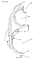
- FIG. 37 is a front view of the retention block of FIG. 31 ;
- FIG. 38 is a perspective view showing the rear, top, and inside of a first piece of the retention block of FIG. 31 ;
- FIG. 39 is a top view of the first retention block piece of FIG. 38 ;
- FIG. 40 is a right side (inside) view of the first retention block piece of FIG. 38 ;
- FIG. 41 is a bottom view of the first retention block piece of FIG. 38 ;
- FIG. 42 is a front view of the first retention block piece of FIG. 38 ;
- FIG. 43 is a cross-sectional view of the first retention block piece of FIG. 38 taken along section line 43 - 43 of FIG. 40 ;
- FIG. 44 is a rear view of the first retention block piece of FIG. 38 ;
- FIG. 45 is an enlarged partial view of the first retention block piece of FIG. 38 taken as indicated from FIG. 44 ;
- FIG. 46 is a perspective view showing the rear, top, and outside of a second piece of the retention block of FIG. 31 ;
- FIG. 47 is a top view of the second retention block piece of FIG. 46 ;
- FIG. 48 is a left side (inside) view of the second retention block piece of FIG. 46 ;
- FIG. 49 is a bottom view of the second retention block piece of FIG. 46 ;
- FIG. 50 is a front view of the second retention block piece of FIG. 46 ;
- FIG. 51 is a cross-sectional view of the second retention block piece of FIG. 46 taken along section line 51 - 51 of FIG. 48 ;
- FIG. 52 is a rear view of the second retention block piece of FIG. 46 ;
- FIG. 53 is an enlarged partial view of the second retention block piece of FIG. 46 taken as indicated from FIG. 52 ;
- FIG. 54 shows a first preparation step for the tether cable of FIG. 6 used at the mid-span breakout location of FIG. 3 ;
- FIG. 55 shows an initial preparation of the distribution cable of FIG. 2 at the mid-span breakout location of FIG. 3 ;
- FIG. 56 shows a second preparation step for the tether of FIG. 54 ;
- FIG. 57 is an enlarged cross-sectional view of the tether of FIG. 56 taken along section line 57 - 57 of FIG. 56 ;
- FIG. 58 is a cross-sectional view of an alternate tether similar to that shown in FIG. 57 .
- the present disclosure relates to mid-span breakout arrangements provided on distribution cables.
- FIG. 2 shows an example distribution cable 220 including six separate buffer tubes 222 each containing twelve optical fibers 224 .
- the fibers can include either ribbon fibers or loose fibers.
- the buffer tubes 222 may be gel filled.
- the distribution cable 220 also includes a central strength member 226 for reinforcing the cable 220 .
- the distribution cable 220 further includes an outer jacket 230 that encloses the buffer tubes 222 .
- ripcords 232 can be provided for facilitating tearing away portions of the jacket 230 to access the optical fibers 224 within the jacket 230 .
- the distribution cable 220 can also include a strength layer 228 for providing further tensile reinforcement to the distribution cable 220 .
- the strength layer includes a plurality of strength members such as aramid yarn (i.e., KEVLAR®) for further reinforcing the cable.
- the distribution cable 220 of FIG. 2 is merely one example of a type of cable to which the various aspects of the present disclosure apply.
- the distribution cable can include an outer jacket enclosing a single buffer tube and at least two strength members extending on opposite sides of the single buffer tube.
- An outer strength member such as aramid yarn can surround the single buffer tube within the jacket.
- the single buffer tube can enclose loose fibers or ribbon fibers.
- a typical mid-span breakout location is provided at an intermediate point along the length of a distribution cable.
- one or more tethers branch out from the distribution cable at the breakout location.
- Each tether most commonly has a fewer number of fibers as compared to the number of fibers provided within the distribution cable. In an example embodiment, each tether has no more than twelve fibers.
- the tethers include fibers that extend between first and second ends. The first ends of the tether fibers are preferably spliced to selected fibers of the distribution cable at the breakout location. The second ends of the tether fibers can either be connectorized or unconnectorized. In certain embodiments, the tether 244 is less than 3 feet long.
- the tether 244 is more than 3 feet long. In certain embodiments, the tether forms a drop cable. In other embodiments, the tether forms a stub cable. In certain embodiments, the tether extends to an intermediate access locations 104 . In other embodiments, the tether may extend to the premises of an end user 115 . In still other embodiments, the tether may extend to a fiber distribution hub (FDH) 130 .
- FDH fiber distribution hub
- FIGS. 3-5 illustrate a fiber optic cable assembly 240 having features that are examples of inventive aspects in accordance with the principles of the present disclosure.
- the fiber optic cable assembly includes a distribution cable 220 and tethers 244 that branch from the distribution cable 220 at a mid-span breakout location 246 .
- Multi-fiber optic connectors 243 are mounted at free ends of the tethers 244 .
- the breakout location 246 includes splice locations 245 where selected optical fibers 224 dc of the main distribution cable 220 are spliced to corresponding optical fibers 224 t of the tethers 244 .
- Splice sleeves 248 are provided over the splices at the splice locations 245 .
- the splice sleeves 248 are within a protective sleeve 250 (e.g., a plastic tube) that extends along a length of the breakout location 246 and has a first end 252 supported by a breakout block 254 and an opposite second end 256 supported by a retention block 258 .
- a protective sleeve 250 e.g., a plastic tube
- the breakout location 246 has a front end 292 and a rear end 294 that correspond to a common field installation process of pulling the front end 292 through a conduit 105 first with the rear end 294 and the tethers 244 trailing. Other installation processes are also possible.
- the breakout block 254 of the mid-span breakout location 246 is secured (e.g., bonded) to the distribution cable 220 and functions to guide the optical fibers 224 dc outwardly from the distribution cable 220 into the first end 252 of the protective sleeve 250 .
- the retention block 258 of the mid-span breakout location 246 is also secured (e.g., bonded) to the distribution cable 220 and functions to direct the optical fibers 224 , from the tethers 244 into the second end 256 of the protective sleeve 250 .
- the retention block 258 further functions to anchor the tethers 244 to the distribution cable 220 .
- An over-mold 260 is provided at the breakout location 246 for covering the breakout components (e.g., the breakout block 254 , the protective sleeve 250 and the retention block 258 ).
- the over-mold 260 forms a flexible, protective enclosure/package that surrounds the distribution cable 220 and seals mid-span breakout location 246 .
- a wrap of heat resistant tape 263 can be wrapped about the distribution cable 220 at the mid-span breakout location 246 to provide an intermediate layer between the breakout components and the over-mold 260 .
- a non-heat resistant tape can be substituted for the heat resistant tape 263 .
- Wrapping the heat resistant tape 263 about and between the breakout block 254 and the retention block 258 , as shown in FIG. 5 , may also provide a fixturing function in the manufacturing process (e.g., securing various pieces together during the over-mold 260 application process).
- the heat resistant tape 263 may be used to prevent the over-mold material from flowing into undesired areas during the over-mold 260 application process.
- FIG. 6 is a cross-sectional view representative of an example configuration for the tethers 244 joined to the distribution cable 220 at the breakout location 246 .
- the depicted configuration has a flat profile and includes a central buffer tube 262 containing a plurality of optical fibers 224 t (e.g., typically one to twelve loose or ribbonized fibers).
- Strength members 264 e.g., flexible rods formed by glass fiber reinforced epoxy
- An outer jacket 266 surrounds the strength members 264 and the buffer tube 262 .
- the outer jacket 266 includes an outer perimeter having an elongated transverse cross-sectional shape.
- An additional strength layer 265 e.g., aramid yarn
- the tethers 244 When the tethers 244 are secured to the distribution cable 220 , the tethers 244 should each preferably be able to withstand a pullout force of at least 100 pounds. To meet this pullout force requirement, the retention block 258 is used to strengthen the mechanical interface between the tethers 244 and the distribution cable 220 .
- the optical fibers 224 t of the tethers 244 are terminated at the multi-fiber fiber optic connectors 243 mounted at the free ends of the tethers 244 .
- the over-mold 260 prefferably be sized with a cross-sectional shape sufficient to allow the breakout location to be readily passed through a one and one-half inch inner diameter conduit or a one and one-quarter inch inner diameter conduit.
- the breakout location has a cross-sectional area that can be passed through a one inch inner diameter conduit.
- the mid-span breakout location 246 is preferably configured to be bent/flexed in any orientation without damaging the optical fibers 224 dc , 224 t and without significantly negatively affecting cable performance. In one embodiment, this flexibility is provided by making sure that the optical fibers 224 dc , 224 t have sufficient excess fiber length (i.e., slack) to allow the breakout location to be bent/flexed the requisite amount. In one embodiment, the optical fibers 224 dc , 224 t that extend along the mid-span breakout location 246 are provided with at least 2% excess fiber length. Further details regarding providing excess fiber length at a breakout location can be found at U.S.
- the mid-span breakout location 246 includes a tensile reinforcing arrangement that mechanically ties or links the breakout block 254 to the retention block 258 .
- the tensile reinforcing structure assists in maintaining the spacing S by resisting stretching of the over-mold 260 at the mid-span breakout location 246 .
- the tensile reinforcing arrangement includes a tensile reinforcing member 270 that extends between the breakout block 254 and the retention block 258 , and is anchored to the breakout block 254 and the retention block 258 .
- the tensile reinforcing member 270 is a flexible member such as a rope, string, strand, or wire.
- the tensile reinforcing member 270 is constructed of aramid yarn (i.e., KEVLAR®).
- the breakout block 254 and the retention block 258 include features that facilitate anchoring the tensile reinforcing member 270 thereto.
- the breakout block 254 includes two anchoring posts 272 1 , 272 2 and an anchoring tab 273 1 .
- the anchoring post 272 1 , 272 2 and the anchoring tab 273 1 are centered along a plane P 1 (see FIGS. 9 and 11 ) that bisects the breakout block 254 and also bisects the distribution cable 220 .
- the anchoring posts 272 1 , 272 2 are positioned at one side of the distribution cable 220 while the anchoring tab 273 1 is located at the opposite side of the distribution cable 220 . As depicted in FIG.
- the anchoring posts 272 1 , 272 2 are located at top side of the breakout block 254 while the anchoring tab 273 1 is located at a bottom side of the breakout block 254 .
- the retention block 258 also includes an anchoring post 272 3 and an anchoring tab 273 2 .
- the anchoring post 272 3 and anchoring tab 273 2 are centered along a plane P 2 (see FIGS. 33 and 35 ) that bisects the retention block 258 and also bisects the distribution cable 220 . As shown in FIG.
- the anchoring post 272 3 is located at a top side of the retention block 258 in axial alignment with the anchoring posts 272 1 , 272 2 of the breakout block 254
- the anchoring tab 273 2 is located at a bottom side of the retention block 258 in axial alignment with the anchoring tab 273 1 of the breakout block 254 .
- the plane P 1 bisecting the breakout block 254 and the plane P 2 bisecting the retention block 258 are preferably coplanar when the breakout block 254 and the retention block 258 are mounted on the distribution cable 220 .
- the tensile reinforcing member 270 includes a first segment 270 1 and a second segment 270 2 .
- the first segment 270 1 extends from the breakout block 254 to the retention block 258 at a location on a first side (e.g., a bottom side) of the distribution cable 220 .
- the second segment 270 2 extends from the breakout block 254 to the retention block 258 at an opposite second side (e.g., a top side) of the distribution cable 220 .
- the first and second segments 270 1 , 270 2 are preferably generally parallel to the central axis of the distribution cable 220 .
- Portions of the tensile reinforcing member 270 are wrapped about and/or tied to the anchoring posts 272 1 - 272 3 and the anchoring tabs 273 1 , 273 2 to mechanically secure the tensile reinforcing member 270 to the breakout block 254 and the retention block 258 .
- the anchoring tabs 273 1 , 273 2 assist in maintaining the first segment 270 1 of the tensile reinforcing member 270 centered along the bottom side of the distribution cable 220 .
- Centering members 276 provided on the breakout block 254 and the retention block 258 assist in maintaining the second segment 270 2 of the tensile reinforcing member 270 centered along a top side of the protective sleeve 250 .
- the first and second segments 270 1 , 270 2 cooperate to provide tensile reinforcement to the breakout location 246 to maintain the spacing S between the breakout block 254 and the retention block 258 .
- the first and second segments 270 1 , 270 2 also provide reinforcing redundancy such that reinforcement is still provided in the event one of the segments breaks.
- the tensile reinforcing member 270 is initially wrapped about or tied to the anchoring post 272 1 and routed down to anchoring tab 273 1 .
- the tensile reinforcing member 270 is then routed about the anchoring tab 273 1 and extended from the anchoring tab 273 1 across the bottom of the mid-span breakout location 246 to the anchoring tab 273 2 .
- the tensile reinforcing member 270 then loops about the anchoring tab 273 2 and is routed back to the anchoring tab 273 1 where the tensile reinforcing member 270 loops about the tab 273 1 and is routed back up to the anchoring post 272 1 .
- the tensile reinforcing member 270 is wrapped about or tied to the anchoring post 272 1 so that the first segment 270 1 is independently anchored. Thereafter, the tensile reinforcing member 270 is routed from the anchoring post 272 1 to the anchoring post 272 2 where the tensile reinforcing member 270 is wrapped about or tied to the anchoring post 272 2 . The tensile reinforcing member 270 is then routed from the anchoring post 272 2 to the anchoring post 272 3 , is wrapped about or tied to the anchoring post 272 3 , and is then routed back to the anchoring post 272 2 .
- the tensile reinforcing member 270 is then wrapped about or tied to the anchoring post 272 2 to provide independent anchoring of the second segment 270 2 .
- the tensile reinforcing member 270 can be wrapped multiple times about the breakout block 254 and the retention block 258 (e.g., looped about the top and bottom sides of the blocks 254 , 258 ) to provide for further anchoring of the tensile reinforcing member 270 . Wrapping the tensile reinforcing member 270 about the breakout block 254 and the retention block 258 , as shown in FIG.
- the tensile reinforcing member 270 may also provide a fixturing function in the manufacturing process (e.g., securing various pieces together during the over-mold 260 application process).
- the tensile reinforcing member 270 can include multiple separate pieces.
- the tensile reinforcing member 270 can be secured to the breakout block 254 and the retention block 258 by a bonding material.
- the tensile reinforcing member 270 may significantly contribute to the strength of the mid-span breakout location 246 and carry a significant portion of a tensile load applied across the breakout location 246 .
- the tensile reinforcing member 270 may develop significant friction with the over-mold 260 and/or the heat resistant tape 263 . This friction may further contribute to stretch resistance across the breakout location 246 .
- the breakout block 254 provided at the mid-span breakout location 246 includes a first piece 300 1 ( FIGS. 13-21 ) that forms a right side of the breakout block 254 and a second piece 300 2 ( FIGS. 22-30 ) that forms a left side of the breakout block 254 .
- the first and second pieces 300 1 , 300 2 are connected at an upper seam 302 and a lower seam 304 .
- a bonding material e.g., epoxy
- the breakout block 254 defines a straight-through channel 306 and a breakout channel 308 .
- the straight-through channel 306 has an inner diameter 310 that generally matches the inner diameter of the outer jacket 230 of the distribution cable 220 .
- the breakout channel 308 is configured to separate the accessed optical fibers 224 dc from the distribution cable 220 by routing the optical fibers 224 dc outwardly from the distribution cable 220 to the protective sleeve 250 .
- the breakout channel 308 includes an opening 312 (see FIGS. 16 and 25 ) for routing the optical fibers 224 dc radially outwardly from the distribution cable 220 into the breakout channel 308 .
- the breakout channel 308 also includes a second opening 314 (see FIGS. 16 and 25 ) for routing the optical fibers 224 dc outwardly from the breakout channel 308 and into the protective sleeve 250 .
- the opening 314 is oriented along an axis 316 that is generally parallel to the central axis of the distribution cable 220 . As best shown at FIG. 8 , the opening 314 is defined by a cylindrical stem 315 sized to fit within the first end 252 of the protective sleeve 250 .
- the breakout block 254 also includes structure for enhancing the mechanical interlock provided between the breakout block 254 and the over-mold 260 .
- first and second sets of parallel fins 320 , 322 project outwardly from opposite sides of the main body of the breakout block 254 .
- the fins 320 , 322 can also be used to facilitate wrapping the tensile reinforcing member 270 about the breakout block 254 .
- the tensile reinforcing member 270 can be wrapped around the breakout block 254 at a location between the sets of fins 320 , 322 such that the fins prevent the wrap from sliding off the breakout block 254 .
- the tensile reinforcing member 270 can be wrapped between the fins 320 and tabs 324 to prevent the wrapped tensile reinforcing member 270 from sliding off the breakout block 254 .
- the upper and lower seams 302 , 304 of the breakout block 254 are preferably configured to prevent over-mold material from seeping into the interior of the breakout block 254 during the over-molding process.
- the first piece 300 1 has an outer overlap member 326 (see FIG. 21 ) that extends substantially along the entire length of the upper seam 302 .
- a recess 328 is positioned below the outer overlap member 326 .
- the second piece 300 2 of the breakout block 254 includes an inner overlap member 330 (see FIG. 30 ) that extends substantially along the entire length of the upper seam 302 .
- a recess 332 is positioned above the inner overlap member 330 .
- the outer overlap member 326 of the first piece 300 1 overlaps the inner overlap member 330 of the second piece 300 2 .
- the lower seam 304 has a similar configuration with the first piece 300 1 having an outer overlap member 334 (see FIG. 19 ) that extends along the length of the lower seam 304 and a recess 336 positioned above the outer overlap member 334 , and the second piece 300 2 having an inner overlap member 338 (see FIG. 27 ) that extends along the length of the lower seam 304 and a recess 340 positioned below the inner overlap member 338 .
- the inner overlap member 338 overlaps the outer overlap member 334 and fits in recess 336 while the outer overlap member 334 fits within recess 340 .
- a bonding material such as epoxy is used to secure the first and second pieces 300 1 , 300 2 of the breakout block 254 together.
- the bonding material can be applied along the upper and lower seams 302 , 304 .
- Bonding material is also applied to a bottom surface 342 of the straight-through channel 306 to secure the breakout block 254 to the distribution cable 220 . It is desirable to prevent the bonding material from entering the breakout channel 308 so that the optical fibers 224 dc are not exposed to the bonding material.
- the breakout block 254 includes overlapping members or fins 343 that form a dam or barrier positioned below the upper seam 302 .
- the breakout block 254 also includes barrier ribs 346 that extend across the entrance opening 312 of the breakout channel 308 .
- the barrier ribs 346 are oriented generally parallel to the longitudinal axis of the distribution cable 220 .
- the bonding material is applied to the bottom surface 342 at a location below the barrier ribs 346 .
- the barrier ribs 346 engage the sides of the distribution cable 220 to form a barrier that prevents the bonding material from migrating upwardly into the breakout channel 308 .
- the breakout block 254 includes a front end 350 positioned opposite from a back end 352 .
- the straight-through channel 306 extends through the breakout block 254 from the front end 350 to the back end 352 .
- the exit opening 314 of the breakout channel 308 defined by the cylindrical stem 315 is positioned at the back end 352 of the breakout block 254 .
- the front end 350 of the breakout block 254 includes a semi-circular skirt or extension 353 that extends rearwardly from a front end face 355 of the breakout block 254 .
- the extension 353 has an inner diameter that is generally equal to the outer diameter of the outer jacket 230 of the distribution cable 220 .
- the front end face 355 of the breakout block 254 abuts against an end surface 231 (see FIG. 55 ) of the outer jacket 230 and the extension 353 overlaps the outer jacket 230 .
- the breakout block 254 also includes curved overlap members 360 positioned along the breakout channel 308 .
- the curved overlap members 360 define a curved inner surface 362 that has a curvature designed to prevent the optical fibers 224 dc from being bent beyond acceptable bend radius requirements. Additionally, the curved overlap members 360 are configured to overlap and nest with one another to assist in maintaining alignment between the first and second pieces 300 1 , 300 2 of the breakout block when the pieces 300 1 , 300 2 are inserted together during assembly.
- the retention block 258 used at the mid-span breakout location 246 includes a first piece 400 1 (see FIGS. 38-45 ) that forms a left side of the retention block 258 and a second piece 400 2 (see FIGS. 46-53 ) that forms a right side of the retention block 258 .
- the retention block 258 includes a front end 402 positioned opposite from a back end 404 .
- the first and second pieces 400 1 , 400 2 of the retention block 258 are joined together at upper and lower seams 406 , 408 that extend generally from the front end 402 to the rear end 404 of the retention block 258 .
- a bonding material such as epoxy can be used to secure the first and second pieces 400 1 , 400 2 together at the upper and lower seams 406 , 408 .
- the retention block 258 also includes structure for enhancing the mechanical interlock provided between the retention block 258 and the over-mold 260 .
- groves 482 shown in FIGS. 31 and 32 ) project inwardly from opposite sides of the main body of the retention block 258 .
- the retention block 258 defines a generally cylindrical straight-through passage 410 that extends through the retention block 258 in a direction extending from the front end 402 to the back end 404 .
- the straight-through passage 410 defines an inner diameter sized to correspond with the inner diameter of the outer jacket 230 of the distribution cable 220 .
- the distribution cable 220 extends through the straight-through passage 410 and is bonded to the straight-through passage 410 .
- the retention block 258 also defines a tether passage arrangement 412 that passes through the retention block 258 in the direction extending from the front end 402 to the back end 404 .
- the tether passage arrangement 412 is adapted for receiving ends of the tethers 244 .
- the tether passage arrangement 412 Adjacent the front end 402 of the retention block 258 , the tether passage arrangement 412 is defined by a generally cylindrical stem 414 that fits within the second end 256 of the protective sleeve 250 . At the rear end 404 of the retention block 258 , the tether passage arrangement defines two tether receptacles 416 . Each tether receptacle 416 includes an outer pocket 418 (see FIGS. 40 and 48 ) sized to receive a jacketed end of one of the tethers 244 . When the tether is mounted within the tether receptacle 416 , an end wall 269 (see FIG.
- each tether anchor portion 430 includes a central buffer tube receiver 432 and strength member receivers 434 positioned on opposite sides of the central buffer tube receiver 432 .
- Crimp recesses 452 are provided along the tether anchor portions 430 to engage a crimp 282 secured to the tether strength members 264 .
- the central buffer tubes 262 of the tethers 244 are bonded within the central buffer tube receivers 432 and the strength members 264 of the tethers are bonded (e.g., with epoxy) within the strength member receivers 434 .
- the optical fibers 224 t of the tethers 244 are routed through the tether passage arrangement 412 and into the protective sleeve 250 where the optical fibers 224 t are spliced to the optical fibers 224 dc of the distribution cable 220 .
- each tether 244 is stripped away to expose the central buffer tube 262 and the strength members 264 (see FIG. 54 ).
- the central buffer tube 262 and the strength members 264 project outwardly beyond the end 269 of the outer jacket 266 .
- the strength layer 265 has been removed from around the exposed buffer tube 262 . After removing the end portion of the outer jacket 266 , the strength members 264 are trimmed and an end portion of the central buffer tube 262 is removed to expose the optical fibers 224 t .
- the crimp 282 is then secured to the tether strength members 264 as shown in FIGS. 56 and 57 .
- the crimp 282 can be secured to both strength members 264 , or separate crimps 282 can each be secured to each strength member 264 as shown in FIG. 58 .
- a crimp tool may be used to secure the crimp 282 to the strength member 264 providing an accurate and consistent attachment location.
- the crimp 282 engages the crimp recess 452 of the retention block 258 thereby securing the tether 244 .
- the accurate and repeatable location of the crimp 282 may be used to facilitate an accurate and repeatable assembly process.
- a portion of the outer jacket 230 is first ring cut and stripped away (see FIG. 55 ) to provide a stripped region 500 having an upstream end 502 and a downstream end 504 .
- the outer strength member 228 can also be displaced (e.g., bunched at the bottom side of the cable) adjacent the ends 502 , 504 to facilitate accessing the buffer tubes 222 .
- One of the buffer tubes 222 is then selected and a first window 508 is cut into the buffer tube adjacent the upstream end 502 of the stripped region 500 and a second window 510 is cut into the buffer tube 222 adjacent the downstream end 504 of the stripped region 500 .
- optical fibers 224 dc desired to be broken out are then accessed and severed at the second window 510 .
- the optical fibers 224 dc are pulled from the buffer tube 222 through the first window 508 (see FIG. 55 ).
- the optical fibers 224 dc are ready to be terminated to the prepared tether 244 of FIG. 54 .
- the protective sleeve 250 is first slid over the exterior of the pre-prepared tethers 244 .
- the splice sleeves 248 can also be slid over the optical fibers 224 t of each of the tethers 244 .
- a polymeric binder or resin is then applied to the ends of the exposed optical fibers 224 dc , 224 t to encase and ribbonize the ends of the optical fibers 224 dc , 224 t .
- the ribbonized ends of the optical fibers 224 dc , 224 t are then fusion spliced together.
- the splice sleeves 248 are slid over the fusion splices to protect the splice locations 245 .
- the breakout block 254 is mounted to the distribution cable 220 .
- a bonding material can be applied to the bottom surface 342 of the straight-through channel 306 and the bonding material can also be applied along the upper and lower seams 302 , 304 .
- the first and second pieces 300 1 , 300 2 of the breakout block 254 are then mounted over the distribution cable 220 adjacent the upstream end 502 of the stripped region 500 . As so positioned, the bottom surface 342 is bonded to the outer strength layer 228 provided at the stripped region of the distribution cable 220 .
- the end 231 of the jacket 230 abuts against the end face 355 provided at the front end of the breakout block 254 , and the semi-circular extension 353 at the front end of the breakout block 254 extends over the outer jacket 230 .
- the optical fibers 224 dc are positioned to extend through the breakout channel 308 and out the opening 314 of the breakout channel 308 .
- the protective sleeve 250 is slid over the optical fibers 224 dc , 224 t such that the first end 252 fits over the cylindrical stem 315 provided at the rear end of the breakout block 254 .
- the retention block 258 is mounted at the downstream end 504 of the stripped region 500 .
- a bonding material can be applied to the upper and lower seams 406 , 408 , to the interior of the straight-through passage 410 , to the central buffer tube receivers 432 and to the strength member receivers 434 .
- the first and second pieces 400 1 , 400 2 of the retention block 258 are then mounted around the distribution cable 220 with the tether optical fibers 224 t extending through the tether passage arrangement 412 and the stripped region 500 of the distribution cable 220 extending through the straight through-channel 410 .
- central buffer tubes 262 of the tethers 244 are positioned within the central buffer tube receivers 432 and the strength members 264 of the tethers 244 are positioned within the strength member receivers 434 .
- the bonding material provided in the straight-through passage 410 provides a bond between the strength layer 228 of the distribution cable 220 and the retention block 258 .
- the cylindrical stem 414 of the retention block 258 is then inserted into the second end 256 of the protective sleeve 250 .
- the tensile reinforcing member 270 can be secured to the assembly in the manner previously described. Thereafter, the heat resistant tape 263 can be wrapped about the mid-span breakout location 246 . Finally, the over-mold layer 260 is over-molded about the mid-span breakout location 246 to complete the manufacturing process. Thereafter, the distribution cable 220 can be spooled.
- optical fibers 224 t of the tether pre-terminated to the optical fibers 224 dc of the distribution cable. “Pre-terminated” means that the optical fibers 224 t are fused or otherwise connected to the optical fibers 224 dc of the distribution cable 220 at the factory as part of the cable manufacturing process rather than being field terminated. The remainder of the mid-span breakout assembly is also preferably factory installed.
- the term “fiber access location” can be any type of location where a fiber can be routed out of a buffer tube.
- Example fiber access locations include windows, ring cut regions, or other openings in a buffer tube.
- the optical fibers 224 dc , 224 t can collectively be referred to as an optical fiber structure.
- the optical fiber structure includes a first length of optical fiber within the distribution cable, a second length of optical fiber that extends through the breakout location and a third length of optical fiber that extends through the tether.
- the first, second and third lengths are in optical communication with one another so as to define a signal path that extends from the distribution cable, through the breakout location, to the end of the tether.
- optical fiber structure also includes lengths of optical fibers that do not include intermediate splices.
- breakout portions of optical fiber include portions of optical fiber that extend along the length of a breakout location.
Abstract
Description
Claims (25)
Priority Applications (3)
| Application Number | Priority Date | Filing Date | Title |
|---|---|---|---|
| US11/787,218 US7609925B2 (en) | 2007-04-12 | 2007-04-12 | Fiber optic cable breakout configuration with tensile reinforcement |
| PCT/US2008/058220 WO2008127852A1 (en) | 2007-04-12 | 2008-03-26 | Fiber optic cable breakout configuration with tensile reinforcement |
| ARP080101499A AR066026A1 (en) | 2007-04-12 | 2008-04-11 | MULTICONNECTION CONFIGURATION OF OPTICAL FIBER CABLES WITH TRACTIONAL REINFORCEMENT |
Applications Claiming Priority (1)
| Application Number | Priority Date | Filing Date | Title |
|---|---|---|---|
| US11/787,218 US7609925B2 (en) | 2007-04-12 | 2007-04-12 | Fiber optic cable breakout configuration with tensile reinforcement |
Publications (2)
| Publication Number | Publication Date |
|---|---|
| US20080253729A1 US20080253729A1 (en) | 2008-10-16 |
| US7609925B2 true US7609925B2 (en) | 2009-10-27 |
Family
ID=39590821
Family Applications (1)
| Application Number | Title | Priority Date | Filing Date |
|---|---|---|---|
| US11/787,218 Active US7609925B2 (en) | 2007-04-12 | 2007-04-12 | Fiber optic cable breakout configuration with tensile reinforcement |
Country Status (3)
| Country | Link |
|---|---|
| US (1) | US7609925B2 (en) |
| AR (1) | AR066026A1 (en) |
| WO (1) | WO2008127852A1 (en) |
Cited By (15)
| Publication number | Priority date | Publication date | Assignee | Title |
|---|---|---|---|---|
| US20090174160A1 (en) * | 2007-10-16 | 2009-07-09 | Adc Telecommunications, Inc. | Method for manufacturing fiber optic cable and related equipment for use in manufacturing fiber optic cable |
| US20090252464A1 (en) * | 2008-04-04 | 2009-10-08 | Baker Hughes Incorporated | Fiber deployment assembly and method |
| US20100135630A1 (en) * | 2007-02-07 | 2010-06-03 | David Frederick Hawkins | Cable duct restraining device |
| US20100158453A1 (en) * | 2008-12-22 | 2010-06-24 | Joseph Todd Cody | Distribution Cable Assembly Having Mid-Span Access Location |
| US20100209059A1 (en) * | 2009-02-16 | 2010-08-19 | Conrad Craig M | Micromodule Cables and Breakout Cables Therefor |
| WO2013025855A1 (en) * | 2011-08-16 | 2013-02-21 | Corning Cable Systems Llc | Preconnectorized cable assemblies for indoor/outdoor applications |
| US8731354B2 (en) | 2010-07-30 | 2014-05-20 | Corning Cable Systems Llc | Array cable assemblies |
| US8842954B2 (en) | 2012-05-02 | 2014-09-23 | Corning Cable Systems Llc | Cable assembly |
| US9507102B2 (en) | 2013-05-02 | 2016-11-29 | Corning Optical Communications LLC | Connector assemblies and methods for providing sealing and strain-relief |
| US20170343433A1 (en) * | 2009-11-13 | 2017-11-30 | Optasense Holdings Limited | Optic Fibres and Fibre Optic Sensing |
| US9893813B2 (en) | 2009-03-05 | 2018-02-13 | Commscope Technologies Llc | Methods, systems, and devices for integrating wireless technology into a fiber optic network |
| US10379311B1 (en) | 2018-04-04 | 2019-08-13 | Northrop Grumman Systems Corporation | Over-molded multi-optical fiber ribbon cable and method of making same |
| US10495825B2 (en) | 2010-08-02 | 2019-12-03 | Commscope Technologies Llc | Architecture for a fiber optic network |
| WO2021211346A1 (en) * | 2020-04-15 | 2021-10-21 | Corning Research & Development Corporation | An interconnect system and methods of installing the same |
| US20210356687A1 (en) * | 2016-05-23 | 2021-11-18 | CommScope Connectivity Belgium BVBA | Optical termination enclosure with ruggedized self-supporting tethers |
Families Citing this family (9)
| Publication number | Priority date | Publication date | Assignee | Title |
|---|---|---|---|---|
| US7609925B2 (en) * | 2007-04-12 | 2009-10-27 | Adc Telecommunications, Inc. | Fiber optic cable breakout configuration with tensile reinforcement |
| DK2517059T3 (en) * | 2009-12-23 | 2019-02-25 | Prysmian Spa | Microbound optical cable |
| US10379308B2 (en) | 2012-03-19 | 2019-08-13 | Brian D. Coate | Apparatus and method for splicing all-dielectric self-supporting fiber optic cable |
| US9201205B2 (en) | 2013-01-16 | 2015-12-01 | 3M Innovative Properties Company | Telecommunications cable inlet device |
| US9989711B2 (en) * | 2013-03-11 | 2018-06-05 | Commscope Technologies Llc | Fiber optic connector and fiber optic cable assembly with fiber optic cable anchored to boot of fiber optic connector |
| US10451830B2 (en) * | 2016-12-29 | 2019-10-22 | Corning Optical Communications LLC | Fiber optic cable assembly and fabrication method using sequentially arranged boots for multi-fiber ferrule |
| US10712519B2 (en) | 2017-06-28 | 2020-07-14 | Corning Research & Development Corporation | High fiber count pre-terminated optical distribution assembly |
| MX2020010133A (en) | 2018-03-29 | 2020-10-19 | Corning Res & Dev Corp | Pre-mold assembly for branched optical cable and related method. |
| US11531178B2 (en) * | 2020-05-07 | 2022-12-20 | viaPhoton, Inc. | Fiber breakout assembly |
Citations (122)
| Publication number | Priority date | Publication date | Assignee | Title |
|---|---|---|---|---|
| US2047152A (en) | 1932-10-22 | 1936-07-07 | Galvin Mfg Corp | Automobile radio cable |
| US3076737A (en) | 1957-11-15 | 1963-02-05 | Fred T Roberts & Company | Corrugated annularly reinforced hose and method for its manufacture |
| US3691505A (en) | 1970-08-20 | 1972-09-12 | Gen Electric | Heater cable splice and method of forming |
| US3750058A (en) | 1971-12-08 | 1973-07-31 | Bell Telephone Labor Inc | Waveguide structure utilizing compliant helical support |
| US3845552A (en) | 1972-03-02 | 1974-11-05 | Method of making an encapsulated assembly | |
| US3879575A (en) | 1974-02-21 | 1975-04-22 | Bell Telephone Labor Inc | Encapsulating compound and closure |
| US3912855A (en) | 1973-04-20 | 1975-10-14 | John T Thompson | Encapsulating splice assembly |
| US3912854A (en) | 1970-01-26 | 1975-10-14 | John T Thompson | Encapsulated conductor junction |
| US4085286A (en) | 1974-09-27 | 1978-04-18 | Raychem Corporation | Heat-recoverable sealing article with self-contained heating means and method of sealing a splice therewith |
| US4107451A (en) | 1975-11-19 | 1978-08-15 | Trech, Inc. | Reinforced splice joint and method of making same |
| US4146302A (en) | 1975-06-02 | 1979-03-27 | General Cable Corporation | Construction of cable made of optical fibres |
| US4152539A (en) | 1977-10-21 | 1979-05-01 | Northern Telecom Limited | Telecommunication cable splices |
| US4322573A (en) | 1980-03-11 | 1982-03-30 | Northern Telecom Limited | Encapsulation of telecommunications cable splices |
| US4343844A (en) | 1980-11-17 | 1982-08-10 | Eaton Corporation | Shrinkable sleeve adapted for cable and tubing gas flow blocking |
| US4405083A (en) | 1982-03-19 | 1983-09-20 | Northern Telecom Limited | Moulding apparatus for encapsulating cable splices |
| US4413881A (en) | 1979-07-26 | 1983-11-08 | Northern Telecom Limited | Optical fiber hermetic seal |
| US4467137A (en) | 1982-06-21 | 1984-08-21 | Raychem Limited | Cable breakout article |
| US4475935A (en) | 1981-07-24 | 1984-10-09 | Nippon Telegraph & Telephone Public Corporation | Joining method to obtain elongated coated optical fiber |
| US4481380A (en) | 1982-08-26 | 1984-11-06 | Alden Research Foundation | High voltage insulator for electrical components having telescoping insulative sleeves |
| US4490315A (en) | 1982-02-04 | 1984-12-25 | Northern Telecom Limited | Methods of moulding of plastics articles |
| US4512628A (en) | 1983-05-31 | 1985-04-23 | Gte Products Corporation | Splice casing assembly |
| US4528419A (en) | 1983-12-12 | 1985-07-09 | Northern Telecom Limited | Forming of cable splice closures |
| US4528150A (en) | 1982-09-23 | 1985-07-09 | Northern Telecom Limited | Methods and apparatus for sealing articles |
| US4549039A (en) | 1983-06-08 | 1985-10-22 | Northern Telecom Limited | Telecommunications cable splice closures |
| US4550220A (en) | 1983-11-04 | 1985-10-29 | National Industries, Inc. | Splice insulator assembly |
| US4556281A (en) | 1983-12-19 | 1985-12-03 | Gte Products Corporation | End plug for a fiber optic in-line splice case assembly |
| US4570032A (en) | 1984-09-07 | 1986-02-11 | Northern Telecom Limited | Sealing closure for a cable splice |
| US4581480A (en) | 1984-09-07 | 1986-04-08 | Northern Telecom Limited | Cable splice closure and strain relief |
| US4589939A (en) | 1984-02-17 | 1986-05-20 | Raychem Corporation | Insulating multiple-conductor cables using coated insert means |
| US4591330A (en) | 1984-11-05 | 1986-05-27 | Northern Telecom Limited | Moulding equipment |
| US4592721A (en) | 1982-09-23 | 1986-06-03 | Northern Telecom Limited | Apparatus for sealably encapsulating articles |
| US4595256A (en) | 1982-04-08 | 1986-06-17 | Les Cables De Lyon | Connection between the ends of two undersea optical fiber cables and method of manufacturing said connection |
| US4609773A (en) | 1985-07-08 | 1986-09-02 | Northern Telecom Limited | Seal assembly |
| US4625073A (en) | 1985-03-11 | 1986-11-25 | Raychem Corporation | Cable having a branch-off region sealed with a branch-off article and method of making same |
| US4629597A (en) | 1985-07-08 | 1986-12-16 | Northern Telecom Limited | Forming of cable splice closures |
| US4648919A (en) | 1984-09-18 | 1987-03-10 | Raychem Corp. | Protection of cable splice |
| US4648606A (en) | 1985-07-08 | 1987-03-10 | Northern Telecom Limited | Seals |
| US4654474A (en) | 1985-06-19 | 1987-03-31 | Northern Telecom Limited | Forming of cable splice closures |
| US4666537A (en) | 1980-04-24 | 1987-05-19 | Thomas & Betts Corporation | Method of sealing and repairing electrical cables |
| US4670069A (en) | 1984-09-18 | 1987-06-02 | Raychem Corp. | Protection of cable splice |
| US4670980A (en) | 1985-06-28 | 1987-06-09 | Northern Telecom Limited | Manufacture of sealing closures for a telecommunications cable splice |
| US4678866A (en) | 1985-07-08 | 1987-07-07 | Northern Telecom Limited | Forming of cable splice closures |
| US4684764A (en) | 1985-12-09 | 1987-08-04 | Amerace Corporation | High voltage cable splice protector |
| US4691081A (en) | 1986-04-16 | 1987-09-01 | Comm/Scope Company | Electrical cable with improved metallic shielding tape |
| US4701574A (en) | 1985-02-06 | 1987-10-20 | Raychem Corp. | Cable sealing apparatus |
| US4725035A (en) | 1985-06-28 | 1988-02-16 | Northern Telecom Limited | Apparatus for manufacture of sealing closures for a telecommunications cable splice |
| US4732628A (en) | 1980-04-24 | 1988-03-22 | Thomas & Betts Corporation | Method of sealing and repairing electrical cables |
| US4747020A (en) | 1986-05-16 | 1988-05-24 | Adc Telecommunications, Inc. | Wire distribution apparatus |
| US4759602A (en) | 1981-03-12 | 1988-07-26 | Siemens Aktiengesellschaft | Method of manufacturing an optical transmission element |
| US4761052A (en) | 1986-01-31 | 1988-08-02 | N. V. Raychem S.A. | Optical fibre splice case |
| US4764232A (en) | 1986-09-26 | 1988-08-16 | Raychem Corporation | Method of protecting a cable splice with a splice closure having pressure measuring means |
| US4818824A (en) | 1987-08-19 | 1989-04-04 | American Telephone And Telegraph Company, At&T Bell Laboratories | Closure for aerial telephone cable splices |
| US4822434A (en) | 1986-07-10 | 1989-04-18 | Yazaki Corporation | Method for forming cover layer over wire joint |
| US4822134A (en) | 1986-10-14 | 1989-04-18 | Raychem Corp. | Optical fiber cable marker |
| US4826277A (en) | 1987-10-30 | 1989-05-02 | Amp Incorporated | Transition of a multiple fiber cable to single fiber cable |
| US4875952A (en) | 1984-06-11 | 1989-10-24 | American Telephone And Telegraph Company, At&T Bell Laboratories | Forced encapsulation means for a cable |
| US4884863A (en) | 1989-03-06 | 1989-12-05 | Siecor Corporation | Optical fiber splicing enclosure for installation in pedestals |
| US4913512A (en) | 1983-12-19 | 1990-04-03 | Gte Products Corporation | Fiber optic in-line splice case assembly |
| US4961623A (en) | 1989-09-05 | 1990-10-09 | Siecor Corporation | Preterminated optical cable |
| US4963698A (en) | 1985-05-02 | 1990-10-16 | Raychem Corporation | Cable sealing |
| US4983013A (en) | 1988-08-30 | 1991-01-08 | Siemens Aktiengesellschaft | Optical cable comprising a carrier member |
| US4983333A (en) | 1989-02-16 | 1991-01-08 | Siecor Corporation | Method for controlling excess fiber length in a loose tube optical fiber buffer tube |
| US4985185A (en) | 1988-03-10 | 1991-01-15 | Siemens Aktiengesellschaft | Method for manufacturing an optical cable |
| US5004315A (en) | 1983-10-20 | 1991-04-02 | Furukawa Electric Co., Ltd. | Optical cable and optical cable line |
| US5018825A (en) | 1989-06-14 | 1991-05-28 | Bicc Public Limited Company | Overhead optical transmission system |
| US5042901A (en) | 1990-07-31 | 1991-08-27 | Siecor Corporation | Preconnectorized optical splice closure |
| US5046811A (en) | 1989-07-17 | 1991-09-10 | Jung Roger E | Junction box for optical communications cords, and gland assembly for cord |
| US5054868A (en) | 1990-08-29 | 1991-10-08 | The United States Of America As Represented By The Secretary Of The Navy | Armored optical fiber cable interconnection for dual payout systems |
| US5066095A (en) | 1990-02-09 | 1991-11-19 | Alcatel Cable | Jointing box for optical fiber cables |
| US5074808A (en) | 1991-02-06 | 1991-12-24 | Amp Incorporated | Molded strain relief in back shell |
| US5097529A (en) | 1991-03-22 | 1992-03-17 | At&T Bell Laboratories | Space-saving optical fiber cable closure |
| US5099088A (en) | 1989-07-19 | 1992-03-24 | Three Bond Co., Ltd. | Means for splicing wires |
| US5115105A (en) | 1990-02-21 | 1992-05-19 | Amphenol Corporation | Overbraided in-line data bus loom |
| US5121458A (en) | 1991-04-05 | 1992-06-09 | Alcatel Na Cable Systems, Inc. | Preterminated fiber optic cable |
| US5125060A (en) | 1991-04-05 | 1992-06-23 | Alcatel Na Cable Systems, Inc. | Fiber optic cable having spliceless fiber branch and method of making |
| US5163116A (en) | 1989-06-28 | 1992-11-10 | Siemens Aktiengesellschaft | Optical cable with at least one optical waveguide |
| US5185844A (en) | 1991-07-29 | 1993-02-09 | At&T Bell Laboratories | Closure for optical fiber connective arrangements and method of providing same |
| US5194692A (en) | 1990-09-27 | 1993-03-16 | Amphenol Corporation | Uncased data bus coupler |
| US5210812A (en) * | 1991-04-05 | 1993-05-11 | Alcatel Na Cable Systems, Inc. | Optical fiber cable having spliced fiber branch and method of making the same |
| US5217808A (en) | 1989-11-29 | 1993-06-08 | At&T Bell Laboratories | Water blocked cable portion and methods of making same |
| US5241611A (en) | 1989-10-04 | 1993-08-31 | British Telecommunications Public Limited Company | Cable joint |
| US5245151A (en) | 1989-04-07 | 1993-09-14 | Minnesota Mining And Manufacturing Company | Method and article for microwave bonding of splice closure |
| US5283014A (en) | 1991-06-21 | 1994-02-01 | Siemens Aktiengesellschaft | Method and apparatus for manufacturing an optical cable |
| US5347089A (en) | 1990-06-22 | 1994-09-13 | Raychem Limited | Branch off |
| US5353367A (en) | 1993-11-29 | 1994-10-04 | Northern Telecom Limited | Distribution frame and optical connector holder combination |
| US5371824A (en) | 1992-09-30 | 1994-12-06 | Siecor Corporation | Buffer tube material for the pedestal environment |
| US5376196A (en) | 1991-07-11 | 1994-12-27 | Kabelmetal Electro Gmbh | Method for sealing the end of a heat-shrunk sleeve |
| US5378853A (en) | 1992-01-29 | 1995-01-03 | Filotex | Shielded multibranch harness |
| US5394502A (en) | 1993-12-21 | 1995-02-28 | United Technologies Corporation | Fiber optic cable harness break-out fitting |
| US5402515A (en) | 1994-03-01 | 1995-03-28 | Minnesota Mining And Manufacturing Company | Fiber distribution frame system, cabinets, trays and fiber optic connector couplings |
| US5410105A (en) | 1992-09-21 | 1995-04-25 | Nitto Denko Corporation | Method for waterproofing junction of main and branch wires and cover therefor |
| USRE34955E (en) | 1989-07-31 | 1995-05-30 | Adc Telecommunications, Inc. | Optical fiber distribution frame |
| US5420958A (en) | 1990-05-21 | 1995-05-30 | Minnesota Mining And Manufacturing Company | Optical fiber distribution center |
| US5440665A (en) * | 1993-04-16 | 1995-08-08 | Raychem Corporation | Fiber optic cable system including main and drop cables and associated fabrication method |
| US5442726A (en) | 1994-02-22 | 1995-08-15 | Hubbell Incorporated | Optical fiber storage system |
| US5450517A (en) | 1994-07-01 | 1995-09-12 | The Whitaker Corporation | Re-enterable fiber optic splicer for data communications |
| US5456959A (en) | 1990-10-09 | 1995-10-10 | Raychem Corporation | Environmental antioxidant wrap/enclosure for an aerial enclosure |
| US5491766A (en) | 1993-04-16 | 1996-02-13 | Raychem Corporation | Bonding assembly for fiber optic cable and associated method |
| US5509202A (en) | 1992-11-19 | 1996-04-23 | The United States Of America As Represented By The Secretary Of The Navy | Hydrostatic sealing sleeve method for utilizing wire connections |
| US5517592A (en) | 1993-10-22 | 1996-05-14 | Kabelmetal Electro Gmbh | Sleeve for branch or joint areas in optical or electrical cables |
| US5997186A (en) * | 1998-05-13 | 1999-12-07 | Huynh; Van L. | Hybrid cable splice closure and related methods |
| US20040223699A1 (en) * | 2000-05-26 | 2004-11-11 | Melton Stuart R. | Figure-eight preconnectorized fiber optic drop cables and assemblies |
| US20050053342A1 (en) * | 2000-05-26 | 2005-03-10 | Melton Stuart R. | Fiber optic drop cables and preconnectorized assemblies having toning portions |
| US20050111800A1 (en) * | 2003-11-26 | 2005-05-26 | Cooke Terry L. | Pre-connectorized fiber optic distribution cable having multifiber connector |
| US20050265672A1 (en) * | 2004-05-27 | 2005-12-01 | Thomas Theuerkorn | Distribution cable having articulated optical connection nodes |
| US20060153517A1 (en) * | 2004-11-03 | 2006-07-13 | Randy Reagan | Methods for configuring and testing fiber drop terminals |
| US20060193594A1 (en) * | 2005-02-28 | 2006-08-31 | Greenwood Jody L | Distribution fiber optic cables having at least one access optical fiber |
| US20070025668A1 (en) * | 2005-07-29 | 2007-02-01 | Greenwood Jody L | Fiber optic cables and assemblies for fiber to the subscriber applications |
| US20070098339A1 (en) * | 2002-12-19 | 2007-05-03 | Bringuier Anne G | Dry fiber optic cables and assemblies |
| US20070104446A1 (en) * | 2005-11-10 | 2007-05-10 | Adc Telecommunications, Inc. | Fiber optic cable breakout system, packaging arrangement, and method of installation |
| US20070212005A1 (en) * | 2006-03-09 | 2007-09-13 | Adc Telecommunications, Inc. | Mid-span breakout with helical fiber routing |
| US20070212009A1 (en) * | 2006-03-09 | 2007-09-13 | Adc Telecommunications, Inc. | Fiber optic cable breakout configuration with retention block |
| US7272283B2 (en) * | 2005-11-01 | 2007-09-18 | Corning Cable Systems, Llc. | Distribution fiber optic cables for fiber to the subscriber applications |
| US7272282B1 (en) * | 2006-07-31 | 2007-09-18 | Corning Cable Systems. Llc. | Fiber optic cables and assemblies suitable for distribution |
| US20070263965A1 (en) * | 2006-05-11 | 2007-11-15 | Cody Joseph T | Tools and methods for manufacturing fiber optic distribution cables |
| US20080013898A1 (en) * | 2006-07-11 | 2008-01-17 | Wells Dennis R | Multi-piece protective mold |
| US7330621B2 (en) * | 2004-05-24 | 2008-02-12 | Corning Cable Systems Llc | Flexible optical closure and other flexible optical assemblies |
| US20080089652A1 (en) * | 2006-10-13 | 2008-04-17 | Dennis Ray Wells | Overmold zip strip |
| US20080175542A1 (en) * | 2007-01-24 | 2008-07-24 | Yu Lu | Hardened fiber optic adapter |
| US20080175541A1 (en) * | 2007-01-24 | 2008-07-24 | Yu Lu | Hardened fiber optic connector |
| US20080253729A1 (en) * | 2007-04-12 | 2008-10-16 | Erik Gronvall | Fiber optic cable breakout configuration with tensile reinforcement |
| US20080253722A1 (en) * | 2007-04-12 | 2008-10-16 | Erik Gronvall | Fiber optic telecommunications cable assembly |
Family Cites Families (40)
| Publication number | Priority date | Publication date | Assignee | Title |
|---|---|---|---|---|
| JPH07107570B2 (en) * | 1989-11-07 | 1995-11-15 | 株式会社フジクラ | Optical fiber cable branch connection |
| DE4214377A1 (en) * | 1992-04-30 | 1993-11-04 | Siemens Ag | Shrink wrapped branching sleeve for optical cables - has plastic housing for splicing point, end pieces with cable passages, supporting body and shrink wrapped rubber sleeve outside |
| EP0584600A1 (en) * | 1992-08-13 | 1994-03-02 | RXS Schrumpftechnik-Garnituren GmbH | Method for tapping individual optical fibers from an uncut optical cable and device used for this method |
| DE4312121B4 (en) * | 1993-04-14 | 2004-04-15 | CCS Technology, Inc., Wilmington | Optical cable with several optical fibers arranged in a given structure |
| DE4314520C1 (en) * | 1993-05-03 | 1994-07-07 | Ant Nachrichtentech | Cuff set for optical fibre communications cable |
| US5425121A (en) * | 1994-02-02 | 1995-06-13 | Siecor Corporation | Cable assembly for use with opto-electronic equipment enclosures |
| US5416874A (en) * | 1994-07-01 | 1995-05-16 | Siecor Corporation | Optical receiver stub fitting |
| AU4259596A (en) * | 1994-12-01 | 1996-06-19 | Akzo Nobel N.V. | Sealing strip for sealing pipe connections |
| DE19517118A1 (en) * | 1995-05-10 | 1996-11-14 | Siemens Ag | Optical fibre transmission element for optical or electrical cable |
| DE19542637A1 (en) * | 1995-11-15 | 1997-05-22 | Siemens Ag | Tap joint or Tee-box for optical fibre cables |
| US5892870A (en) * | 1995-11-16 | 1999-04-06 | Fiber Connections Inc. | Fibre optic cable connector |
| US5861575A (en) * | 1996-03-19 | 1999-01-19 | Broussard; Blaine L. | Device and method for a fluid stop splice for a submersible cable |
| US6376774B1 (en) * | 1996-08-22 | 2002-04-23 | Littelfuse Inc. | Housing for cable assembly |
| US5734776A (en) * | 1996-08-28 | 1998-03-31 | Adc Telecommunications, Inc. | Outside plant cross-connect apparatus |
| US5767448A (en) * | 1996-09-30 | 1998-06-16 | Raychem Corporation | Sealing device |
| US6407338B1 (en) * | 1997-01-15 | 2002-06-18 | Uniseal, Inc. | Composite sealant and splice case therefor |
| DE59813727D1 (en) * | 1997-02-14 | 2006-11-02 | Nexans Deutschland Ind Ag & Co | Arrangement for branching to a telecommunications cable containing a plurality of stranding elements with optical fibers |
| US6215930B1 (en) * | 1998-05-11 | 2001-04-10 | Bellsouth Intellectual Property Management Corporation | Remote-splitter fiber optic cable |
| EP1001294A1 (en) * | 1998-11-13 | 2000-05-17 | Alcatel | Lightwaveguide with mantle |
| JP4053202B2 (en) * | 1999-08-11 | 2008-02-27 | トヨクニ電線株式会社 | Optical communication trunk cable branch and optical communication trunk cable |
| US6706968B2 (en) * | 2000-04-24 | 2004-03-16 | Tyco Electronics Corporation | Environmentally sealed wrap-around sleeves having a longitudinal sealant chamber |
| US6539160B2 (en) * | 2000-10-27 | 2003-03-25 | Corning Cable Systems Llc | Optical fiber splicing and connecting assembly with coupler cassette |
| US6466725B2 (en) * | 2000-11-29 | 2002-10-15 | Corning Cable Systems Llc | Apparatus and method for splitting optical fibers |
| US6619697B2 (en) * | 2000-12-27 | 2003-09-16 | Nkf Kabel B.V. | Y-branch splittable connector |
| US6579014B2 (en) * | 2001-09-28 | 2003-06-17 | Corning Cable Systems Llc | Fiber optic receptacle |
| US6813421B2 (en) * | 2001-12-26 | 2004-11-02 | Corning Cable Systems Llc | Fiber optic cable having a ripcord |
| EP1468319A2 (en) * | 2002-01-23 | 2004-10-20 | Tyco Electronics Raychem N.V. | Optical fibre tube sealing |
| US20040016564A1 (en) * | 2002-07-25 | 2004-01-29 | 3M Innovative Properties Company | Expanded insulating sleeve with edge support |
| US7086539B2 (en) * | 2002-10-21 | 2006-08-08 | Adc Telecommunications, Inc. | High density panel with rotating tray |
| US7035510B2 (en) * | 2003-07-02 | 2006-04-25 | Adc Telecommunications, Inc. | Fiberoptic furcation device with crimp |
| US6866430B1 (en) * | 2003-08-22 | 2005-03-15 | Sci Systems, Inc. | Cable splicing apparatus and method |
| US6856748B1 (en) * | 2003-09-30 | 2005-02-15 | Corning Cable Systems Llc | Interconnection enclosure having a connector port and preterminated optical connector |
| US7184633B2 (en) * | 2003-11-26 | 2007-02-27 | Corning Cable Systems Llc | Preterminated fiber optic distribution cable |
| US7006739B2 (en) * | 2003-12-15 | 2006-02-28 | Corning Cable Systems Llc | Pre-connectorized fiber optic distribution cable |
| US7120347B2 (en) * | 2004-01-27 | 2006-10-10 | Corning Cable Systems Llc | Multi-port optical connection terminal |
| US7197214B2 (en) * | 2004-05-24 | 2007-03-27 | Corning Cable Systems Llc | Methods and apparatus for facilitating cable locating |
| US7228036B2 (en) * | 2004-11-30 | 2007-06-05 | Corning Cable Systems Llc | Adjustable tether assembly for fiber optic distribution cable |
| KR20080003433A (en) * | 2005-04-19 | 2008-01-07 | 에이디씨 텔레커뮤니케이션스 인코포레이티드 | Loop back plug and method |
| WO2008021253A2 (en) * | 2006-08-14 | 2008-02-21 | Adc Telecommunications, Inc. | Factory spliced cable assembly |
| US7480436B2 (en) * | 2006-10-10 | 2009-01-20 | Adc Telecommunications, Inc. | Systems and methods for securing a tether to a distribution cable |
-
2007
- 2007-04-12 US US11/787,218 patent/US7609925B2/en active Active
-
2008
- 2008-03-26 WO PCT/US2008/058220 patent/WO2008127852A1/en active Application Filing
- 2008-04-11 AR ARP080101499A patent/AR066026A1/en unknown
Patent Citations (125)
| Publication number | Priority date | Publication date | Assignee | Title |
|---|---|---|---|---|
| US2047152A (en) | 1932-10-22 | 1936-07-07 | Galvin Mfg Corp | Automobile radio cable |
| US3076737A (en) | 1957-11-15 | 1963-02-05 | Fred T Roberts & Company | Corrugated annularly reinforced hose and method for its manufacture |
| US3912854A (en) | 1970-01-26 | 1975-10-14 | John T Thompson | Encapsulated conductor junction |
| US3691505A (en) | 1970-08-20 | 1972-09-12 | Gen Electric | Heater cable splice and method of forming |
| US3750058A (en) | 1971-12-08 | 1973-07-31 | Bell Telephone Labor Inc | Waveguide structure utilizing compliant helical support |
| US3845552A (en) | 1972-03-02 | 1974-11-05 | Method of making an encapsulated assembly | |
| US3912855A (en) | 1973-04-20 | 1975-10-14 | John T Thompson | Encapsulating splice assembly |
| US3879575A (en) | 1974-02-21 | 1975-04-22 | Bell Telephone Labor Inc | Encapsulating compound and closure |
| US4085286A (en) | 1974-09-27 | 1978-04-18 | Raychem Corporation | Heat-recoverable sealing article with self-contained heating means and method of sealing a splice therewith |
| US4146302A (en) | 1975-06-02 | 1979-03-27 | General Cable Corporation | Construction of cable made of optical fibres |
| US4107451A (en) | 1975-11-19 | 1978-08-15 | Trech, Inc. | Reinforced splice joint and method of making same |
| US4152539A (en) | 1977-10-21 | 1979-05-01 | Northern Telecom Limited | Telecommunication cable splices |
| US4413881A (en) | 1979-07-26 | 1983-11-08 | Northern Telecom Limited | Optical fiber hermetic seal |
| US4322573A (en) | 1980-03-11 | 1982-03-30 | Northern Telecom Limited | Encapsulation of telecommunications cable splices |
| US4666537A (en) | 1980-04-24 | 1987-05-19 | Thomas & Betts Corporation | Method of sealing and repairing electrical cables |
| US4732628A (en) | 1980-04-24 | 1988-03-22 | Thomas & Betts Corporation | Method of sealing and repairing electrical cables |
| US4343844A (en) | 1980-11-17 | 1982-08-10 | Eaton Corporation | Shrinkable sleeve adapted for cable and tubing gas flow blocking |
| US4759602A (en) | 1981-03-12 | 1988-07-26 | Siemens Aktiengesellschaft | Method of manufacturing an optical transmission element |
| US4475935A (en) | 1981-07-24 | 1984-10-09 | Nippon Telegraph & Telephone Public Corporation | Joining method to obtain elongated coated optical fiber |
| US4490315A (en) | 1982-02-04 | 1984-12-25 | Northern Telecom Limited | Methods of moulding of plastics articles |
| US4405083A (en) | 1982-03-19 | 1983-09-20 | Northern Telecom Limited | Moulding apparatus for encapsulating cable splices |
| US4595256A (en) | 1982-04-08 | 1986-06-17 | Les Cables De Lyon | Connection between the ends of two undersea optical fiber cables and method of manufacturing said connection |
| US4467137A (en) | 1982-06-21 | 1984-08-21 | Raychem Limited | Cable breakout article |
| US4481380A (en) | 1982-08-26 | 1984-11-06 | Alden Research Foundation | High voltage insulator for electrical components having telescoping insulative sleeves |
| US4528150A (en) | 1982-09-23 | 1985-07-09 | Northern Telecom Limited | Methods and apparatus for sealing articles |
| US4592721A (en) | 1982-09-23 | 1986-06-03 | Northern Telecom Limited | Apparatus for sealably encapsulating articles |
| US4512628A (en) | 1983-05-31 | 1985-04-23 | Gte Products Corporation | Splice casing assembly |
| US4549039A (en) | 1983-06-08 | 1985-10-22 | Northern Telecom Limited | Telecommunications cable splice closures |
| US5004315A (en) | 1983-10-20 | 1991-04-02 | Furukawa Electric Co., Ltd. | Optical cable and optical cable line |
| US4550220A (en) | 1983-11-04 | 1985-10-29 | National Industries, Inc. | Splice insulator assembly |
| US4528419A (en) | 1983-12-12 | 1985-07-09 | Northern Telecom Limited | Forming of cable splice closures |
| US4556281A (en) | 1983-12-19 | 1985-12-03 | Gte Products Corporation | End plug for a fiber optic in-line splice case assembly |
| US4913512A (en) | 1983-12-19 | 1990-04-03 | Gte Products Corporation | Fiber optic in-line splice case assembly |
| US4589939A (en) | 1984-02-17 | 1986-05-20 | Raychem Corporation | Insulating multiple-conductor cables using coated insert means |
| US4875952A (en) | 1984-06-11 | 1989-10-24 | American Telephone And Telegraph Company, At&T Bell Laboratories | Forced encapsulation means for a cable |
| US4581480A (en) | 1984-09-07 | 1986-04-08 | Northern Telecom Limited | Cable splice closure and strain relief |
| US4570032A (en) | 1984-09-07 | 1986-02-11 | Northern Telecom Limited | Sealing closure for a cable splice |
| US4648919A (en) | 1984-09-18 | 1987-03-10 | Raychem Corp. | Protection of cable splice |
| US4670069A (en) | 1984-09-18 | 1987-06-02 | Raychem Corp. | Protection of cable splice |
| US4591330A (en) | 1984-11-05 | 1986-05-27 | Northern Telecom Limited | Moulding equipment |
| US4701574A (en) | 1985-02-06 | 1987-10-20 | Raychem Corp. | Cable sealing apparatus |
| US4625073A (en) | 1985-03-11 | 1986-11-25 | Raychem Corporation | Cable having a branch-off region sealed with a branch-off article and method of making same |
| US4963698A (en) | 1985-05-02 | 1990-10-16 | Raychem Corporation | Cable sealing |
| US4654474A (en) | 1985-06-19 | 1987-03-31 | Northern Telecom Limited | Forming of cable splice closures |
| US4670980A (en) | 1985-06-28 | 1987-06-09 | Northern Telecom Limited | Manufacture of sealing closures for a telecommunications cable splice |
| US4725035A (en) | 1985-06-28 | 1988-02-16 | Northern Telecom Limited | Apparatus for manufacture of sealing closures for a telecommunications cable splice |
| US4629597A (en) | 1985-07-08 | 1986-12-16 | Northern Telecom Limited | Forming of cable splice closures |
| US4648606A (en) | 1985-07-08 | 1987-03-10 | Northern Telecom Limited | Seals |
| US4609773A (en) | 1985-07-08 | 1986-09-02 | Northern Telecom Limited | Seal assembly |
| US4678866A (en) | 1985-07-08 | 1987-07-07 | Northern Telecom Limited | Forming of cable splice closures |
| US4684764A (en) | 1985-12-09 | 1987-08-04 | Amerace Corporation | High voltage cable splice protector |
| US4761052A (en) | 1986-01-31 | 1988-08-02 | N. V. Raychem S.A. | Optical fibre splice case |
| US4691081A (en) | 1986-04-16 | 1987-09-01 | Comm/Scope Company | Electrical cable with improved metallic shielding tape |
| US4747020A (en) | 1986-05-16 | 1988-05-24 | Adc Telecommunications, Inc. | Wire distribution apparatus |
| US4822434A (en) | 1986-07-10 | 1989-04-18 | Yazaki Corporation | Method for forming cover layer over wire joint |
| US4764232A (en) | 1986-09-26 | 1988-08-16 | Raychem Corporation | Method of protecting a cable splice with a splice closure having pressure measuring means |
| US4822134A (en) | 1986-10-14 | 1989-04-18 | Raychem Corp. | Optical fiber cable marker |
| US4818824A (en) | 1987-08-19 | 1989-04-04 | American Telephone And Telegraph Company, At&T Bell Laboratories | Closure for aerial telephone cable splices |
| US4826277A (en) | 1987-10-30 | 1989-05-02 | Amp Incorporated | Transition of a multiple fiber cable to single fiber cable |
| US4985185A (en) | 1988-03-10 | 1991-01-15 | Siemens Aktiengesellschaft | Method for manufacturing an optical cable |
| US4983013A (en) | 1988-08-30 | 1991-01-08 | Siemens Aktiengesellschaft | Optical cable comprising a carrier member |
| US4983333A (en) | 1989-02-16 | 1991-01-08 | Siecor Corporation | Method for controlling excess fiber length in a loose tube optical fiber buffer tube |
| US4884863A (en) | 1989-03-06 | 1989-12-05 | Siecor Corporation | Optical fiber splicing enclosure for installation in pedestals |
| US5245151A (en) | 1989-04-07 | 1993-09-14 | Minnesota Mining And Manufacturing Company | Method and article for microwave bonding of splice closure |
| US5018825A (en) | 1989-06-14 | 1991-05-28 | Bicc Public Limited Company | Overhead optical transmission system |
| US5163116A (en) | 1989-06-28 | 1992-11-10 | Siemens Aktiengesellschaft | Optical cable with at least one optical waveguide |
| US5046811A (en) | 1989-07-17 | 1991-09-10 | Jung Roger E | Junction box for optical communications cords, and gland assembly for cord |
| US5099088A (en) | 1989-07-19 | 1992-03-24 | Three Bond Co., Ltd. | Means for splicing wires |
| USRE34955E (en) | 1989-07-31 | 1995-05-30 | Adc Telecommunications, Inc. | Optical fiber distribution frame |
| US4961623A (en) | 1989-09-05 | 1990-10-09 | Siecor Corporation | Preterminated optical cable |
| US5241611A (en) | 1989-10-04 | 1993-08-31 | British Telecommunications Public Limited Company | Cable joint |
| US5217808A (en) | 1989-11-29 | 1993-06-08 | At&T Bell Laboratories | Water blocked cable portion and methods of making same |
| US5335408A (en) | 1989-11-29 | 1994-08-09 | At&T Bell Laboratories | Method of making a water blocked optical fiber cable |
| US5066095A (en) | 1990-02-09 | 1991-11-19 | Alcatel Cable | Jointing box for optical fiber cables |
| US5115105A (en) | 1990-02-21 | 1992-05-19 | Amphenol Corporation | Overbraided in-line data bus loom |
| US5420958A (en) | 1990-05-21 | 1995-05-30 | Minnesota Mining And Manufacturing Company | Optical fiber distribution center |
| US5347089A (en) | 1990-06-22 | 1994-09-13 | Raychem Limited | Branch off |
| US5042901A (en) | 1990-07-31 | 1991-08-27 | Siecor Corporation | Preconnectorized optical splice closure |
| US5054868A (en) | 1990-08-29 | 1991-10-08 | The United States Of America As Represented By The Secretary Of The Navy | Armored optical fiber cable interconnection for dual payout systems |
| US5194692A (en) | 1990-09-27 | 1993-03-16 | Amphenol Corporation | Uncased data bus coupler |
| US5456959A (en) | 1990-10-09 | 1995-10-10 | Raychem Corporation | Environmental antioxidant wrap/enclosure for an aerial enclosure |
| US5074808A (en) | 1991-02-06 | 1991-12-24 | Amp Incorporated | Molded strain relief in back shell |
| US5097529A (en) | 1991-03-22 | 1992-03-17 | At&T Bell Laboratories | Space-saving optical fiber cable closure |
| US5121458A (en) | 1991-04-05 | 1992-06-09 | Alcatel Na Cable Systems, Inc. | Preterminated fiber optic cable |
| US5125060A (en) | 1991-04-05 | 1992-06-23 | Alcatel Na Cable Systems, Inc. | Fiber optic cable having spliceless fiber branch and method of making |
| US5210812A (en) * | 1991-04-05 | 1993-05-11 | Alcatel Na Cable Systems, Inc. | Optical fiber cable having spliced fiber branch and method of making the same |
| US5283014A (en) | 1991-06-21 | 1994-02-01 | Siemens Aktiengesellschaft | Method and apparatus for manufacturing an optical cable |
| US5376196A (en) | 1991-07-11 | 1994-12-27 | Kabelmetal Electro Gmbh | Method for sealing the end of a heat-shrunk sleeve |
| US5185844A (en) | 1991-07-29 | 1993-02-09 | At&T Bell Laboratories | Closure for optical fiber connective arrangements and method of providing same |
| US5378853A (en) | 1992-01-29 | 1995-01-03 | Filotex | Shielded multibranch harness |
| US5410105A (en) | 1992-09-21 | 1995-04-25 | Nitto Denko Corporation | Method for waterproofing junction of main and branch wires and cover therefor |
| US5371824A (en) | 1992-09-30 | 1994-12-06 | Siecor Corporation | Buffer tube material for the pedestal environment |
| US5509202A (en) | 1992-11-19 | 1996-04-23 | The United States Of America As Represented By The Secretary Of The Navy | Hydrostatic sealing sleeve method for utilizing wire connections |
| US5528718A (en) * | 1993-04-16 | 1996-06-18 | Raychem Corporation | Fiber optic cable system including main and drop cables and associated fabrication method |
| US5440665A (en) * | 1993-04-16 | 1995-08-08 | Raychem Corporation | Fiber optic cable system including main and drop cables and associated fabrication method |
| US5491766A (en) | 1993-04-16 | 1996-02-13 | Raychem Corporation | Bonding assembly for fiber optic cable and associated method |
| US5517592A (en) | 1993-10-22 | 1996-05-14 | Kabelmetal Electro Gmbh | Sleeve for branch or joint areas in optical or electrical cables |
| US5353367A (en) | 1993-11-29 | 1994-10-04 | Northern Telecom Limited | Distribution frame and optical connector holder combination |
| US5394502A (en) | 1993-12-21 | 1995-02-28 | United Technologies Corporation | Fiber optic cable harness break-out fitting |
| US5442726A (en) | 1994-02-22 | 1995-08-15 | Hubbell Incorporated | Optical fiber storage system |
| US5402515A (en) | 1994-03-01 | 1995-03-28 | Minnesota Mining And Manufacturing Company | Fiber distribution frame system, cabinets, trays and fiber optic connector couplings |
| US5450517A (en) | 1994-07-01 | 1995-09-12 | The Whitaker Corporation | Re-enterable fiber optic splicer for data communications |
| US5997186A (en) * | 1998-05-13 | 1999-12-07 | Huynh; Van L. | Hybrid cable splice closure and related methods |
| US20050053342A1 (en) * | 2000-05-26 | 2005-03-10 | Melton Stuart R. | Fiber optic drop cables and preconnectorized assemblies having toning portions |
| US20040223699A1 (en) * | 2000-05-26 | 2004-11-11 | Melton Stuart R. | Figure-eight preconnectorized fiber optic drop cables and assemblies |
| US20070098339A1 (en) * | 2002-12-19 | 2007-05-03 | Bringuier Anne G | Dry fiber optic cables and assemblies |
| US20050111800A1 (en) * | 2003-11-26 | 2005-05-26 | Cooke Terry L. | Pre-connectorized fiber optic distribution cable having multifiber connector |
| US7330621B2 (en) * | 2004-05-24 | 2008-02-12 | Corning Cable Systems Llc | Flexible optical closure and other flexible optical assemblies |
| US20050265672A1 (en) * | 2004-05-27 | 2005-12-01 | Thomas Theuerkorn | Distribution cable having articulated optical connection nodes |
| US20060153517A1 (en) * | 2004-11-03 | 2006-07-13 | Randy Reagan | Methods for configuring and testing fiber drop terminals |
| US20060193594A1 (en) * | 2005-02-28 | 2006-08-31 | Greenwood Jody L | Distribution fiber optic cables having at least one access optical fiber |
| US20070025668A1 (en) * | 2005-07-29 | 2007-02-01 | Greenwood Jody L | Fiber optic cables and assemblies for fiber to the subscriber applications |
| US7272283B2 (en) * | 2005-11-01 | 2007-09-18 | Corning Cable Systems, Llc. | Distribution fiber optic cables for fiber to the subscriber applications |
| US20070104446A1 (en) * | 2005-11-10 | 2007-05-10 | Adc Telecommunications, Inc. | Fiber optic cable breakout system, packaging arrangement, and method of installation |
| US20070212005A1 (en) * | 2006-03-09 | 2007-09-13 | Adc Telecommunications, Inc. | Mid-span breakout with helical fiber routing |
| US20070212009A1 (en) * | 2006-03-09 | 2007-09-13 | Adc Telecommunications, Inc. | Fiber optic cable breakout configuration with retention block |
| US20070263965A1 (en) * | 2006-05-11 | 2007-11-15 | Cody Joseph T | Tools and methods for manufacturing fiber optic distribution cables |
| US20080013898A1 (en) * | 2006-07-11 | 2008-01-17 | Wells Dennis R | Multi-piece protective mold |
| US7272282B1 (en) * | 2006-07-31 | 2007-09-18 | Corning Cable Systems. Llc. | Fiber optic cables and assemblies suitable for distribution |
| US20080089652A1 (en) * | 2006-10-13 | 2008-04-17 | Dennis Ray Wells | Overmold zip strip |
| US7403685B2 (en) * | 2006-10-13 | 2008-07-22 | Adc Telecommunications, Inc. | Overmold zip strip |
| US20080175542A1 (en) * | 2007-01-24 | 2008-07-24 | Yu Lu | Hardened fiber optic adapter |
| US20080175541A1 (en) * | 2007-01-24 | 2008-07-24 | Yu Lu | Hardened fiber optic connector |
| US20080253729A1 (en) * | 2007-04-12 | 2008-10-16 | Erik Gronvall | Fiber optic cable breakout configuration with tensile reinforcement |
| US20080253722A1 (en) * | 2007-04-12 | 2008-10-16 | Erik Gronvall | Fiber optic telecommunications cable assembly |
Non-Patent Citations (6)
| Title |
|---|
| "Cable Assemblies: Molding & Termination," http://www.dgo.com/prodcable.htm, 8 pages (Copyright 2001). |
| "DAM/BLOK(TM) Electrical Splice Kit," http://www.pmiind.com/products/damblok.html, 2 pages (Copyright 2000). |
| "Factory Installed Termination Systems for Fiber Optic Cable Splices," 1 page (Publicly known at least as early as Jul. 21, 2006). |
| "Installation Instructions for Pre-Connectorized MIC(R) Cable (2-6 Fiber) Equipped with Plug & Play(TM) Systems Pulling Grips," Corning Cable Systems, Issue 7, pp. 1-3 (Jul. 2001). |
| "Pre-Connectorized (4-24 Fiber) Fiber Optic Cables Equipped with Plug & Play(TM) Systems Pulling Sleeves and Grips," Corning Cable Systems, Issue 1, pp. 1-7 (Mar. 2005). |
| International Search Report and Written Opinion mailed Aug. 8, 2008. |
Cited By (37)
| Publication number | Priority date | Publication date | Assignee | Title |
|---|---|---|---|---|
| US20100135630A1 (en) * | 2007-02-07 | 2010-06-03 | David Frederick Hawkins | Cable duct restraining device |
| US20090174160A1 (en) * | 2007-10-16 | 2009-07-09 | Adc Telecommunications, Inc. | Method for manufacturing fiber optic cable and related equipment for use in manufacturing fiber optic cable |
| US7976031B2 (en) | 2007-10-16 | 2011-07-12 | Adc Telecommunications, Inc. | Cart Assembly |
| US20130051739A1 (en) * | 2008-04-04 | 2013-02-28 | Carl Stoesz | Fiber deployment assembly and method |
| US20090252464A1 (en) * | 2008-04-04 | 2009-10-08 | Baker Hughes Incorporated | Fiber deployment assembly and method |
| US20090252463A1 (en) * | 2008-04-04 | 2009-10-08 | Baker Hughes Incorporated | Rtci cable and method |
| US7792405B2 (en) | 2008-04-04 | 2010-09-07 | Baker Hughes Incorporated | Fiber deployment assembly and method |
| US8326103B2 (en) * | 2008-04-04 | 2012-12-04 | Baker Hughes Incorporated | Cable and method |
| US20100158453A1 (en) * | 2008-12-22 | 2010-06-24 | Joseph Todd Cody | Distribution Cable Assembly Having Mid-Span Access Location |
| US7941021B2 (en) * | 2008-12-22 | 2011-05-10 | Corning Cable Systems Llc | Distribution cable assembly having mid-span access location |
| US9188758B2 (en) * | 2009-02-16 | 2015-11-17 | Corning Optical Communications LLC | Micromodule cables and breakout cables therefor |
| US8582941B2 (en) * | 2009-02-16 | 2013-11-12 | Corning Cable Systems Llc | Micromodule cables and breakout cables therefor |
| US20140037256A1 (en) * | 2009-02-16 | 2014-02-06 | Corning Cable Systems Llc | Micromodule cables and breakout cables therefor |
| US8934747B2 (en) * | 2009-02-16 | 2015-01-13 | Corning Cable Systems Llc | Micromodule cables and breakout cables therefor |
| US20150139594A1 (en) * | 2009-02-16 | 2015-05-21 | Corning Optical Communications LLC | Micromodule cables and breakout cables therefor |
| US20100209059A1 (en) * | 2009-02-16 | 2010-08-19 | Conrad Craig M | Micromodule Cables and Breakout Cables Therefor |
| US9304275B2 (en) | 2009-02-16 | 2016-04-05 | Corning Optical Communications LLC | Micromodule cables and breakout cables therefor |
| US9893813B2 (en) | 2009-03-05 | 2018-02-13 | Commscope Technologies Llc | Methods, systems, and devices for integrating wireless technology into a fiber optic network |
| US11438070B2 (en) | 2009-03-05 | 2022-09-06 | Commscope Technologies Llc | Methods, systems, and devices for integrating wireless technology into a fiber optic network |
| US11044014B2 (en) | 2009-03-05 | 2021-06-22 | Commscope Technologies Llc | Methods, systems, and devices for integrating wireless technology into a fiber optic network |
| US10630388B2 (en) | 2009-03-05 | 2020-04-21 | Commscope Technologies Llc | Methods, systems, and devices for integrating wireless technology into a fiber optic network |
| US10135534B2 (en) | 2009-03-05 | 2018-11-20 | Commscope Technologies Llc | Methods, systems, and devices for integrating wireless technology into a fiber optic network |
| US20170343433A1 (en) * | 2009-11-13 | 2017-11-30 | Optasense Holdings Limited | Optic Fibres and Fibre Optic Sensing |
| US11099085B2 (en) * | 2009-11-13 | 2021-08-24 | Optasense Holdings Limited | Optic fibres and fibre optic sensing |
| US8731354B2 (en) | 2010-07-30 | 2014-05-20 | Corning Cable Systems Llc | Array cable assemblies |
| US10495825B2 (en) | 2010-08-02 | 2019-12-03 | Commscope Technologies Llc | Architecture for a fiber optic network |
| US10830965B2 (en) | 2010-08-02 | 2020-11-10 | Commscope Technologies Llc | Architecture for a fiber optic network |
| US9709756B2 (en) | 2011-08-16 | 2017-07-18 | Corning Optical Communications LLC | Preconnectorized cable assemblies for indoor/outdoor applications |
| WO2013025855A1 (en) * | 2011-08-16 | 2013-02-21 | Corning Cable Systems Llc | Preconnectorized cable assemblies for indoor/outdoor applications |
| US9285556B2 (en) | 2012-05-02 | 2016-03-15 | Corning Optical Communications LLC | Cable assembly |
| US8842954B2 (en) | 2012-05-02 | 2014-09-23 | Corning Cable Systems Llc | Cable assembly |
| US9507102B2 (en) | 2013-05-02 | 2016-11-29 | Corning Optical Communications LLC | Connector assemblies and methods for providing sealing and strain-relief |
| US20210356687A1 (en) * | 2016-05-23 | 2021-11-18 | CommScope Connectivity Belgium BVBA | Optical termination enclosure with ruggedized self-supporting tethers |
| US10379311B1 (en) | 2018-04-04 | 2019-08-13 | Northrop Grumman Systems Corporation | Over-molded multi-optical fiber ribbon cable and method of making same |
| WO2021211346A1 (en) * | 2020-04-15 | 2021-10-21 | Corning Research & Development Corporation | An interconnect system and methods of installing the same |
| US11474307B2 (en) | 2020-04-15 | 2022-10-18 | Corning Research & Development Corporation | Interconnect system and methods of installing the same |
| US11774684B2 (en) | 2020-04-15 | 2023-10-03 | Corning Research & Development Corporation | Interconnect system and methods of installing the same |
Also Published As
| Publication number | Publication date |
|---|---|
| WO2008127852A1 (en) | 2008-10-23 |
| AR066026A1 (en) | 2009-07-15 |
| US20080253729A1 (en) | 2008-10-16 |
Similar Documents
| Publication | Publication Date | Title |
|---|---|---|
| US7609925B2 (en) | Fiber optic cable breakout configuration with tensile reinforcement | |
| US7532799B2 (en) | Fiber optic telecommunications cable assembly | |
| US7590321B2 (en) | Mid-span breakout with helical fiber routing | |
| US7317863B2 (en) | Fiber optic cable breakout configuration with retention block | |
| JP4733115B2 (en) | Wiring cable assembly with composite molded intermediate branch point | |
| US7251411B1 (en) | Fiber optic cable breakout configuration with “Y” block | |
| US7840109B2 (en) | Factory spliced cable assembly | |
| JP5121448B2 (en) | Wiring cable with composite molded intermediate branch point with preferential bending | |
| US7403685B2 (en) | Overmold zip strip | |
| US7454106B2 (en) | Factory spliced cable assembly | |
| US7422378B2 (en) | Fiber optic cable breakout configuration with excess fiber length | |
| US7424189B2 (en) | Mid-span breakout with potted closure | |
| US7769261B2 (en) | Fiber optic distribution cable | |
| US7289714B1 (en) | Tubing wrap procedure | |
| WOOD | Overmold zip strip |
Legal Events
| Date | Code | Title | Description |
|---|---|---|---|
| AS | Assignment |
Owner name: ADC TELECOMMUNICATION, INC., MINNESOTA Free format text: ASSIGNMENT OF ASSIGNORS INTEREST;ASSIGNORS:GRONVALL, ERIK;SUCK, PAUL;SCHMIDT, ANDY;AND OTHERS;REEL/FRAME:019715/0696 Effective date: 20070619 |
|
| STCF | Information on status: patent grant |
Free format text: PATENTED CASE |
|
| FPAY | Fee payment |
Year of fee payment: 4 |
|
| AS | Assignment |
Owner name: TYCO ELECTRONICS SERVICES GMBH, SWITZERLAND Free format text: ASSIGNMENT OF ASSIGNORS INTEREST;ASSIGNOR:ADC TELECOMMUNICATIONS, INC.;REEL/FRAME:036060/0174 Effective date: 20110930 |
|
| AS | Assignment |
Owner name: COMMSCOPE EMEA LIMITED, IRELAND Free format text: ASSIGNMENT OF ASSIGNORS INTEREST;ASSIGNOR:TYCO ELECTRONICS SERVICES GMBH;REEL/FRAME:036956/0001 Effective date: 20150828 |
|
| AS | Assignment |
Owner name: COMMSCOPE TECHNOLOGIES LLC, NORTH CAROLINA Free format text: ASSIGNMENT OF ASSIGNORS INTEREST;ASSIGNOR:COMMSCOPE EMEA LIMITED;REEL/FRAME:037012/0001 Effective date: 20150828 |
|
| AS | Assignment |
Owner name: JPMORGAN CHASE BANK, N.A., AS COLLATERAL AGENT, ILLINOIS Free format text: PATENT SECURITY AGREEMENT (TERM);ASSIGNOR:COMMSCOPE TECHNOLOGIES LLC;REEL/FRAME:037513/0709 Effective date: 20151220 Owner name: JPMORGAN CHASE BANK, N.A., AS COLLATERAL AGENT, ILLINOIS Free format text: PATENT SECURITY AGREEMENT (ABL);ASSIGNOR:COMMSCOPE TECHNOLOGIES LLC;REEL/FRAME:037514/0196 Effective date: 20151220 Owner name: JPMORGAN CHASE BANK, N.A., AS COLLATERAL AGENT, IL Free format text: PATENT SECURITY AGREEMENT (TERM);ASSIGNOR:COMMSCOPE TECHNOLOGIES LLC;REEL/FRAME:037513/0709 Effective date: 20151220 Owner name: JPMORGAN CHASE BANK, N.A., AS COLLATERAL AGENT, IL Free format text: PATENT SECURITY AGREEMENT (ABL);ASSIGNOR:COMMSCOPE TECHNOLOGIES LLC;REEL/FRAME:037514/0196 Effective date: 20151220 |
|
| FPAY | Fee payment |
Year of fee payment: 8 |
|
| AS | Assignment |
Owner name: COMMSCOPE, INC. OF NORTH CAROLINA, NORTH CAROLINA Free format text: RELEASE BY SECURED PARTY;ASSIGNOR:JPMORGAN CHASE BANK, N.A.;REEL/FRAME:048840/0001 Effective date: 20190404 Owner name: REDWOOD SYSTEMS, INC., NORTH CAROLINA Free format text: RELEASE BY SECURED PARTY;ASSIGNOR:JPMORGAN CHASE BANK, N.A.;REEL/FRAME:048840/0001 Effective date: 20190404 Owner name: COMMSCOPE TECHNOLOGIES LLC, NORTH CAROLINA Free format text: RELEASE BY SECURED PARTY;ASSIGNOR:JPMORGAN CHASE BANK, N.A.;REEL/FRAME:048840/0001 Effective date: 20190404 Owner name: ANDREW LLC, NORTH CAROLINA Free format text: RELEASE BY SECURED PARTY;ASSIGNOR:JPMORGAN CHASE BANK, N.A.;REEL/FRAME:048840/0001 Effective date: 20190404 Owner name: ALLEN TELECOM LLC, ILLINOIS Free format text: RELEASE BY SECURED PARTY;ASSIGNOR:JPMORGAN CHASE BANK, N.A.;REEL/FRAME:048840/0001 Effective date: 20190404 Owner name: REDWOOD SYSTEMS, INC., NORTH CAROLINA Free format text: RELEASE BY SECURED PARTY;ASSIGNOR:JPMORGAN CHASE BANK, N.A.;REEL/FRAME:049260/0001 Effective date: 20190404 Owner name: COMMSCOPE TECHNOLOGIES LLC, NORTH CAROLINA Free format text: RELEASE BY SECURED PARTY;ASSIGNOR:JPMORGAN CHASE BANK, N.A.;REEL/FRAME:049260/0001 Effective date: 20190404 Owner name: ALLEN TELECOM LLC, ILLINOIS Free format text: RELEASE BY SECURED PARTY;ASSIGNOR:JPMORGAN CHASE BANK, N.A.;REEL/FRAME:049260/0001 Effective date: 20190404 Owner name: ANDREW LLC, NORTH CAROLINA Free format text: RELEASE BY SECURED PARTY;ASSIGNOR:JPMORGAN CHASE BANK, N.A.;REEL/FRAME:049260/0001 Effective date: 20190404 Owner name: COMMSCOPE, INC. OF NORTH CAROLINA, NORTH CAROLINA Free format text: RELEASE BY SECURED PARTY;ASSIGNOR:JPMORGAN CHASE BANK, N.A.;REEL/FRAME:049260/0001 Effective date: 20190404 |
|
| AS | Assignment |
Owner name: JPMORGAN CHASE BANK, N.A., NEW YORK Free format text: ABL SECURITY AGREEMENT;ASSIGNORS:COMMSCOPE, INC. OF NORTH CAROLINA;COMMSCOPE TECHNOLOGIES LLC;ARRIS ENTERPRISES LLC;AND OTHERS;REEL/FRAME:049892/0396 Effective date: 20190404 Owner name: WILMINGTON TRUST, NATIONAL ASSOCIATION, AS COLLATE Free format text: PATENT SECURITY AGREEMENT;ASSIGNOR:COMMSCOPE TECHNOLOGIES LLC;REEL/FRAME:049892/0051 Effective date: 20190404 Owner name: JPMORGAN CHASE BANK, N.A., NEW YORK Free format text: TERM LOAN SECURITY AGREEMENT;ASSIGNORS:COMMSCOPE, INC. OF NORTH CAROLINA;COMMSCOPE TECHNOLOGIES LLC;ARRIS ENTERPRISES LLC;AND OTHERS;REEL/FRAME:049905/0504 Effective date: 20190404 Owner name: WILMINGTON TRUST, NATIONAL ASSOCIATION, AS COLLATERAL AGENT, CONNECTICUT Free format text: PATENT SECURITY AGREEMENT;ASSIGNOR:COMMSCOPE TECHNOLOGIES LLC;REEL/FRAME:049892/0051 Effective date: 20190404 |
|
| FEPP | Fee payment procedure |
Free format text: MAINTENANCE FEE REMINDER MAILED (ORIGINAL EVENT CODE: REM.); ENTITY STATUS OF PATENT OWNER: LARGE ENTITY Free format text: 11.5 YR SURCHARGE- LATE PMT W/IN 6 MO, LARGE ENTITY (ORIGINAL EVENT CODE: M1556); ENTITY STATUS OF PATENT OWNER: LARGE ENTITY |
|
| MAFP | Maintenance fee payment |
Free format text: PAYMENT OF MAINTENANCE FEE, 12TH YEAR, LARGE ENTITY (ORIGINAL EVENT CODE: M1553); ENTITY STATUS OF PATENT OWNER: LARGE ENTITY Year of fee payment: 12 |
|
| AS | Assignment |
Owner name: WILMINGTON TRUST, DELAWARE Free format text: SECURITY INTEREST;ASSIGNORS:ARRIS SOLUTIONS, INC.;ARRIS ENTERPRISES LLC;COMMSCOPE TECHNOLOGIES LLC;AND OTHERS;REEL/FRAME:060752/0001 Effective date: 20211115 |