US7607783B2 - Imaging apparatus, image processing apparatus, image processing method of imaging apparatus and computer program - Google Patents
Imaging apparatus, image processing apparatus, image processing method of imaging apparatus and computer program Download PDFInfo
- Publication number
- US7607783B2 US7607783B2 US10/964,538 US96453804A US7607783B2 US 7607783 B2 US7607783 B2 US 7607783B2 US 96453804 A US96453804 A US 96453804A US 7607783 B2 US7607783 B2 US 7607783B2
- Authority
- US
- United States
- Prior art keywords
- image
- original
- projection
- equation
- processing apparatus
- Prior art date
- Legal status (The legal status is an assumption and is not a legal conclusion. Google has not performed a legal analysis and makes no representation as to the accuracy of the status listed.)
- Active, expires
Links
- 238000012545 processing Methods 0.000 title claims abstract description 188
- 238000003384 imaging method Methods 0.000 title claims description 64
- 238000004590 computer program Methods 0.000 title description 3
- 238000003672 processing method Methods 0.000 title description 3
- 230000009466 transformation Effects 0.000 claims abstract description 161
- 238000000034 method Methods 0.000 claims description 116
- 230000008569 process Effects 0.000 claims description 101
- 230000000694 effects Effects 0.000 claims description 98
- 238000012937 correction Methods 0.000 claims description 62
- 239000013598 vector Substances 0.000 claims description 15
- 230000001131 transforming effect Effects 0.000 claims description 4
- 239000011159 matrix material Substances 0.000 description 47
- PXFBZOLANLWPMH-UHFFFAOYSA-N 16-Epiaffinine Natural products C1C(C2=CC=CC=C2N2)=C2C(=O)CC2C(=CC)CN(C)C1C2CO PXFBZOLANLWPMH-UHFFFAOYSA-N 0.000 description 37
- 230000000994 depressogenic effect Effects 0.000 description 34
- 230000015654 memory Effects 0.000 description 33
- 230000008859 change Effects 0.000 description 30
- 230000006870 function Effects 0.000 description 13
- 238000006073 displacement reaction Methods 0.000 description 10
- 239000000284 extract Substances 0.000 description 10
- 230000003287 optical effect Effects 0.000 description 9
- 230000001105 regulatory effect Effects 0.000 description 9
- 238000000605 extraction Methods 0.000 description 8
- 229910052704 radon Inorganic materials 0.000 description 8
- SYUHGPGVQRZVTB-UHFFFAOYSA-N radon atom Chemical compound [Rn] SYUHGPGVQRZVTB-UHFFFAOYSA-N 0.000 description 8
- 230000002087 whitening effect Effects 0.000 description 7
- 230000002093 peripheral effect Effects 0.000 description 6
- 238000010586 diagram Methods 0.000 description 4
- 230000009467 reduction Effects 0.000 description 4
- 238000006243 chemical reaction Methods 0.000 description 3
- 239000007787 solid Substances 0.000 description 3
- 238000004891 communication Methods 0.000 description 2
- 230000033001 locomotion Effects 0.000 description 2
- 230000004044 response Effects 0.000 description 2
- 238000000844 transformation Methods 0.000 description 2
- 230000003936 working memory Effects 0.000 description 2
- 238000012935 Averaging Methods 0.000 description 1
- 230000015556 catabolic process Effects 0.000 description 1
- 239000003086 colorant Substances 0.000 description 1
- 230000006835 compression Effects 0.000 description 1
- 238000007906 compression Methods 0.000 description 1
- 230000001276 controlling effect Effects 0.000 description 1
- 238000006731 degradation reaction Methods 0.000 description 1
- 238000001514 detection method Methods 0.000 description 1
- 238000011161 development Methods 0.000 description 1
- 230000035620 dolor Effects 0.000 description 1
- 238000002372 labelling Methods 0.000 description 1
- 238000012986 modification Methods 0.000 description 1
- 230000004048 modification Effects 0.000 description 1
- 230000007363 regulatory process Effects 0.000 description 1
- 238000005070 sampling Methods 0.000 description 1
- 238000012546 transfer Methods 0.000 description 1
Images


Classifications
-
- G06T3/02—
-
- H—ELECTRICITY
- H04—ELECTRIC COMMUNICATION TECHNIQUE
- H04N—PICTORIAL COMMUNICATION, e.g. TELEVISION
- H04N23/00—Cameras or camera modules comprising electronic image sensors; Control thereof
Definitions
- This invention relates to an imaging apparatus, an image processing apparatus, an imaging method of an image processing apparatus and an image processing computer program.
- a document camera is adapted to pickup an image of the original placed on an original table by the user by means of a camera and the data of the original obtained by picking up the image of the original are stored in the memory of a computer and processed so that the original is enlarged and projected on a screen by means of a projector (see, inter alia, Patent Document 1: Unexamined Japanese Patent Application KOKAI Publication No. 2002-354331 (pp. 2-3, FIG. 1)).
- the picked-up image may contain an unnecessary part. Then, if the image containing such an unnecessary part is processed for luminance, color difference and so on to improve the effects of the image, the image can be improperly processed and, if such an image is projected on a screen, again the viewers will find difficulty in viewing the projected image.
- an imaging apparatus an image processing apparatus, an image processing method of an imaging apparatus and an image processing computer program capable of obtaining a clearly visible image.
- an imaging apparatus for shooting an original including a shape acquiring unit which acquires: (i) an image of the original that is obtained by shooting the original, (ii) a contour of the image of the original that is of an image representing the original within a shot image, and (iii) a shape of the image of the original based on the acquired contour; a correction parameter acquiring unit which acquires image effect correction parameters for correcting an image effect based on only an area of the image of the original whose shape is acquired by the shape acquiring unit; and an image effect processing unit which performs an image effect process for the image of the original by using the image effect correction parameters acquired by the correction parameter acquiring unit.
- the correction parameter acquiring unit comprises a projection parameter acquiring unit which determines projection parameters indicating a relationship between the shape of the image of the original and an actual shape of the original based on the shape of the image of the original acquired by the shape acquiring unit.
- the correction parameter acquiring unit acquires the actual shape of the original from a projected transformed image that is obtained by projection/transformation using the projection parameters determined by the projection parameter acquiring unit and acquires the image effect correction parameters based on the image of the original having the actual shape of the image thus acquired.
- the shape acquiring unit cuts out the image of the original at a specified timing subsequent to acquiring the shape of the image of the original.
- FIG. 1 is a schematic diagram of Embodiment 1 of the present invention, which is an imaging/image projection apparatus;
- FIG. 2 is a schematic block diagram of the document camera in FIG. 1 , illustrating the configuration thereof,
- FIGS. 3A and 3B are schematic illustrations of the function of the image processing apparatus in FIG. 2 ;
- FIG. 4 is a schematic illustration of the keys of the operation unit in FIG. 2 ;
- FIG. 5 is a flowchart of the basic projection process to be executed by the imaging/image projection apparatus of FIG. 1 ;
- FIG. 6 is a schematic illustration of the cutting out process to be executed by the image processing apparatus in FIG. 2 ;
- FIG. 7 is a schematic illustration of the basic concept of extraction of projection parameters and affine transformation
- FIG. 8 is a flowchart of the projection parameter extraction process to be executed by the image processing apparatus in FIG. 2 ;
- FIG. 9 is a flowchart of the quadrangle contour extraction process to be executed by the image processing apparatus in FIG. 2 ;
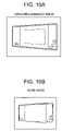
- FIG. 10A is a schematic illustration of a reduced luminance image and FIG. 10B is a schematic illustration of an edge image;
- FIGS. 11A and 11B are schematic illustrations of the function of a Roberts filter
- FIGS. 12A and 12B are schematic illustrations of Radon transformation
- FIGS. 13A and 13B are schematic illustrations of an operation of acquiring data for a polar coordinate system by Radon transformation of a line of an X, Y coordinate system;
- FIG. 14 is a flowchart of the process of detecting a peak point from the data for a polar system to be executed by the image processing apparatus in FIG. 2 ;
- FIGS. 15A , 15 B, 15 C and 15 D are schematic illustrations of the concept of detecting a quadrangle from the lines extracted by detecting peak points;
- FIG. 16 is a flowchart of the quadrangle detection process to be executed by the image processing apparatus in FIG. 2 ;
- FIG. 17 is a flowchart of the quadrangle selection process to be executed by the image processing apparatus in FIG. 2 ;
- FIG. 18 is a flowchart of the process of determining affine parameters from the corners of a quadrangle to be executed by the image processing apparatus of FIG. 2 ;
- FIG. 19 is a schematic illustration of inverse transformation for acquiring the original image from an image obtained after projective transformation
- FIG. 20 is a flowchart of the image transformation process using affine transformation to be executed by the image processing apparatus in FIG. 2 ;
- FIG. 21 is a schematic illustration of an exemplar image cut out by the image processing apparatus in FIG. 2 ;
- FIG. 22A is a schematic illustration of an exemplar luminance histogram and FIG. 22B is a schematic illustration of an exemplar color difference histogram;
- FIG. 23 is a flowchart of the image effect correction parameter extraction process to be executed by the image processing apparatus in FIG. 2 ;
- FIG. 24A is a schematic illustration of the image effect process to be executed when the background color is white and FIG. 24B is a schematic illustration of the image effect process to be executed when the background color is black, whereas FIG. 24C is a schematic illustration of the image effect process to be executed when the background color is other than white and black,
- FIG. 25 is a schematic illustration of an exemplar luminance transformation graph to be used for color adjustment
- FIGS. 26A and 26B are schematic illustrations of whitening the background
- FIG. 27 is a flowchart of the image effect process to be executed by the image processing apparatus in FIG. 2 ;
- FIG. 28 is a flowchart of the background whitening process to be executed by the image processing apparatus in FIG. 2 ;
- FIGS. 29A and 29B are schematic illustrations of an exemplar image for which the image distortion cannot be corrected by projective transformation
- FIG. 30 is a schematic illustration of the corresponding relationship of the original image, the image obtained after projective transformation and an enlarged image obtained after projective transformation;
- FIG. 31 is a former half of a flowchart of the correction adjustment and image transformation process to be executed by the image processing apparatus in FIG. 2 ;
- FIG. 32 is a latter half of a flowchart of the correction adjustment and image transformation process to be executed by the image processing apparatus in FIG. 2 ;
- FIG. 33 is a schematic illustration of Embodiment 2 of the present invention, which is an imaging/image projection apparatus;
- FIG. 34 is a schematic block diagram of the document camera in FIG. 33 , illustrating the configuration thereof;
- FIG. 35 is a flowchart of the basic process to be executed by the document camera in FIG. 34 ;
- FIG. 36 is a former half of a flowchart of the basic document process to be executed by the computer in FIG. 33 ;
- FIG. 37 is a latter half of a flowchart of the basic document process to be executed by the computer in FIG. 33 .
- imaging/image projecting apparatuses adapted to project an image that corresponds to the image of an original obtained by shooting the original.
- FIG. 1 is a schematic diagram of Embodiment 1 of the present invention, which is an imaging/image projection apparatus.
- the imaging/image projection apparatus comprises a document camera 1 and a projector 2 .
- the text/picture (document) camera 1 is a camera system for shooting an object of projection, which is an original 4 and has a camera section 11 , a pillar 12 , a base seat 13 and an operation table 14 .
- the camera section 11 operates to pick up an image of the original 4 .
- a digital camera is used for the camera section 11 .
- the camera section 11 is mounted on the pillar 12 .
- the base seat 13 supports the pillar 12 .
- the document camera 1 has an image data generating unit 21 and a data processing unit 22 .
- the image data generating unit 21 operates for shooting the original 4 and taking in the image data of the original 4 .
- the data processing unit 22 receives the image data taken in by the image data generating unit 21 from the latter and processes them so as to output the processed image data to the projector 2 .
- the image data generating unit 21 and the data processing unit 22 may be arranged in the camera section 11 shown in FIG. 1 or alternatively they may be arranged respectively in the camera section 11 and the operation table 14 .
- the image data generating unit 21 includes an optical lens section 101 and an image sensor 102 .
- the optical lens section 101 includes condenser lens and other lenses for the purpose of picking up an image of the original 4 .
- the image sensor 102 is adapted to take in the image data obtained by digitizing the image formed by the optical lens section 101 that converges beams of light. It includes a CCD (Charge Coupled Device) and other components.
- CCD Charge Coupled Device
- the data processing unit 22 has a memory 201 , a display device 202 , an image processing apparatus 203 , an operation unit 204 , a program code memory device 205 and a CPU (Central Processing Unit) 206 .
- a memory 201 a memory 201 , a display device 202 , an image processing apparatus 203 , an operation unit 204 , a program code memory device 205 and a CPU (Central Processing Unit) 206 .
- CPU Central Processing Unit
- the memory 201 temporarily stores the image from the image sensor 102 and the image data to be transmitted to the display device 202 .
- the display device 202 displays the image to be transmitted to the projector 2 .
- the image processing apparatus 203 performs image processes on the image data temporarily stored in the memory 201 for the purpose of correcting the distortion of the image and processing the image effect.
- the image processing apparatus 203 generates an image of the original 4 same as an image picked up from the right front of the original 4 as shown in FIG. 3B by correcting the distortion (keystone correction) of the image of the original 4 picked up from an angle that is inclined or rotated relative to the imaging plane of the camera section 11 as shown in FIG. 3A .
- the image processing apparatus 203 cuts out a quadrangle from the distorted image of the original 4 and performs an operation of inverse transformation by projection/transformation of the image of the original 4 using the quadrangle in order to correct the distortion of the image.
- the image processing apparatus 203 performs the following operations under the control of the CPU 206 .
- the operation unit 204 includes switches and keys for controlling the document projecting operation. As the user operates any of the keys and the switches, the operation unit 204 transmits information on the operation to the CPU 206 .
- the operation unit 204 has image regulation keys including a upper enlarging key 211 , a lower enlarging key 212 , a left enlarging key 213 , a right enlarging key 214 , a right rotation key 215 , a left rotation key 216 , an enlarging key 217 , a reducing key 218 and a shooting/release key 219 .
- the upper enlarging key 211 , the lower enlarging key 212 , the left enlarging key 213 and the right enlarging key 214 are projection/transformation keys to be used for projection/transformation.
- the upper enlarging key 211 is used to rotate the upper half of the image around a horizontal line passing through the center of the image toward the viewer who compares the upper half and the lower half of the image.
- the lower enlarging key 212 is used to rotate the lower half of the image toward the viewer around the horizontal line.
- the left enlarging key 213 and the right enlarging key 214 are used to regulate the distortion of the left half and that of the right half of the image respectively by rotating the image around a vertical line passing through the center of the image.
- the left enlarging key 213 is operated when the left half of the image is small, whereas the right enlarging key 214 is operated when the right half of the image is small.
- the right rotation key 215 and the left rotation key 216 are rotation correction keys for regulating the rotation of the image.
- the right rotation key 215 is used to rotate the image clockwise, whereas the left rotation key 216 is used to rotate the image counterclockwise.
- the enlarging key 217 and the reducing key 218 are keys for transforming the image.
- the enlarging key 217 is used to enlarge the image, whereas the reducing key 218 is used to reduce the image.
- the memory 201 stores the predetermined ratio for enlargement and reduction. If 2 is selected for the ratio, the image processing apparatus 203 doubles the size of the image when the user depresses the enlarging key 217 once. When the user depresses the enlarging key 217 for another time, the operation unit 204 and the CPU 206 control the image processing apparatus 203 to further double the size of the image in response to the key depression so that consequently the size of the image is quadrupled from that of the original image. When the reducing key 218 is depressed, the size of the enlarged image is reduced to a half. The operation unit 204 and the CPU 206 control the image processing apparatus 203 to reduce the enlarged image.
- the upper enlarging key 211 , the lower enlarging key 212 , the left enlarging key 213 and the right enlarging key 214 operate as cursor keys when the enlarging key 217 is operated. More specifically, the upper enlarging key 211 functions as upward moving key for moving the image of the original 4 being displayed on the display device 202 upward when the enlarging key 217 is operated.
- the lower enlarging key 212 functions as downward moving key for moving the image of the original 4 being displayed on the display device 202 downward when the enlarging key 217 is operated and the left enlarging key 213 functions as leftward moving key for moving the image of the original 4 being displayed on the display device 202 leftward when the enlarging key 217 is operated, whereas the right enlarging key 214 functions as rightward moving key for moving the image of the original 4 being displayed on the display device 202 rightward when the enlarging key 217 is operated.
- the shooting/release key 219 is the key that is operated when shooting the original 4 .
- the program code memory device 205 operates to store the program that the CPU 206 executes. Typically, it comprises a ROM (Read Only Memory).
- the CPU 206 controls the various components according to the program stored in the program code memory device 205 .
- the memory 201 operates also as working memory for the CPU 206 .
- the CPU 206 determines if the image of the original 4 , which is the shooting target (hereinafter referred to as shooting target), is moving or not and switches the imaging mode according to a flowchart, which will be described in greater detail hereinafter.
- the imaging mode includes a movie mode and a still mode.
- the movie mode is selected at the time when the user places the original 4 , whose image he or she wants to project on the base seat 13 . Then, the image picked up by the camera section 11 is projected by the projector 2 .
- the CPU 206 controls the related components so as to project a moving image with a resolution of VGA (Video Graphics Array) (640 ⁇ 480 dots) at a rate of 30 fps (frames per second).
- VGA Video Graphics Array
- the movie mode is a mode where real time has high priority but resolution has low priority.
- the still mode is selected after the user places the original 4 .
- the camera section 11 shoots the original 4 to obtain a high resolution image so as to project a high resolution still image. If the camera section 11 has about 3 million pixels, the still image cut out for projection shows a resolution of XGA (eXtended Graphics Array) (1,024 ⁇ 768).
- XGA extended Graphics Array
- the CPU 206 determines if the image of the original 4 is moving or not in order to select either the movie mode or the still mode. To do this, the CPU 206 firstly determines the quantity of image change MD that is found between the image obtained last time and the current image.
- the quantity of image change MD is the quantity that represents the extent of change that is found between the image obtained last time and the image of the original that is currently being shot.
- the CPU 206 may determine the total sum of the absolute values of the differences of all the pixels from the data of the image obtained by the last shooting operation and the data of the image obtained by the current shooting operation as the quantity of image change MD.
- the quantity of image change MD is expressed by an equation 1 shown below.
- the quantity of image change MD may alternatively be determined by sampling pixels.
- Threshold Thresh 1 and threshold Thresh 2 are defined in advance as thresholds for determining if the image moves or not. In other words, the quantity of image change MD is compared with these thresholds.
- the threshold Thresh 1 is used to determine if there is a move or not.
- the CPU 206 determines that there is no move if the quantity of image change MD is smaller than the threshold Thresh 1.
- the threshold Thresh 2 is used to determine if the move, if any, requires the movie mode to be selected or not. Even if there is a move such as a move of a shadow or that of placing a pen in the still mode, it may not be necessary to select the movie mode provided that the move is smaller than the threshold Thresh 2.
- the threshold Thresh 2 is defined to be higher than the threshold Thresh 1 (Thresh 1 ⁇ Thresh 2).
- the memory 201 stores the thresholds Thresh 1 and Thresh 2 in advance.
- the CPU 206 When the CPU 206 switches from the movie mode to the still mode because there is not any move, it waits for a predetermined period of time. More specifically, the CPU 206 measures the stationary time Ptime after it determines that there is not any move. The memory 201 stores a predetermined period of time Holdtime that is compared with the stationary time Ptime.
- the projector 2 forms an image of the original 4 by projecting light onto a screen 3 .
- the document camera 1 and the projector 2 are connected to each other typically by way of an RGB cable 15 .
- the document camera 1 outputs the image data of the original 4 taken by the camera section 11 to the projector 2 by way of the cable 15 .
- the CPU 206 of the document camera 1 reads out the program code from the program code memory device 205 and executes the basic projection process.
- the CPU 206 initializes the camera defining parameters including those of the focal point the exposure, the white balance of the camera section 11 of the document camera 11 (step S 11 ).
- the CPU 206 initializes the imaging mode to the movie mode (step S 12 ). More specifically, the CPU 206 selects the movie mode for the specified region on the memory 201 in order to initialize the imaging mode. Then, the CPU 206 so controls the operation that the image data read out from the image sensor 102 of the camera section 11 may be used as those of VGA.
- the scene being shot by the camera section 11 is transmitted to the image sensor 102 by way of the optical lens section 101 as converged light and the image sensor 102 prepares a low resolution digital image as movie on the basis of the image of the converged light. Then, the image sensor 102 transmits the prepared digital image periodically to the memory 201 typically at a rate of 30 frames per second.
- the CPU 206 resets the stationary time Ptime (step S 13 ).
- the CPU 206 controls the image sensor 102 and the memory 201 so as to transfer the image data for the low resolution digital image to the memory 201 from the image sensor 102 (step S 14 ). Note that only the image data is transferred to the memory 201 and no image is displayed on the display device 202 . No image is displayed on the display device 202 because the image data for displaying the image on the display device 202 is stored in a region indicated by a different address on the memory 201 .
- the CPU 206 determines the quantity of image change MD between the image obtained last time and the current image according to the equation 1 (step S 15 ).
- the CPU 206 determines if the imaging mode is the movie mode or the still mode (step S 16 ).
- the movie mode is selected for the imaging mode. Therefore, the CPU 206 determines that the imaging mode is the movie mode in the initial state and copies the image data of the moving image stored in the memory 201 to a predetermined region of the memory 201 in order to project the picked-up moving image (step S 17 ). As a result, the display device 202 reads the image data of the picked-up moving image from the memory 201 and outputs the RGB signal to the projector 2 . The projector 2 projects the image according to the signal.
- the CPU 206 compares the above-described predetermined threshold Thresh 1 and the quantity of image change MD determined at step S 15 and determines if there is a move in the image or not on the basis of the outcome of the comparison (step S 18 ).
- the CPU 206 determines that there is a move in the image (YES at step S 18 ) and resets the stationary time Ptime to read the image data for the low resolution digital image. Then, the CPU 206 determines the quantity of image change MD and writes the data in the projection image region of the memory 201 (steps S 13 through S 17 ). As a result, the imaging/image projection apparatus keeps on the movie mode so that a low resolution moving image is projected on the screen 3 .
- the CPU 206 determines that there is no move in the image (NO at step S 18 ) and adds 1 to the stationary time Ptime (step S 19 ).
- the CPU 206 determines if the stationary time Ptime has got to a predetermined period of time HoldTime or not (step S 20 ).
- the CPU 206 If it is determined that the stationary time Ptime has not got to the predetermined period of time HoldTime (NO at step S 20 ) yet, the CPU 206 reads in the image data for the low resolution digital image once again and determines the quantity of image change MD. Then, if there is no longer any move in the image, the CPU 206 adds 1 to the stationary time Ptime (steps S 14 through S 19 ). In this case, since the stationary time Ptime is not reset, it is counted up by the CPU 206 each time the CPU 206 reads the image data for the moving image.
- the CPU 206 determines that the user holds the move of the image and selects the still mode for the imaging mode (step S 21 ).
- the CPU 206 controls the image sensor 102 so as to pick up a high resolution still image (step S 22 ). Then, the CPU 206 writes the image data acquired by the image sensor 102 in the memory 201 . Note that, after writing the image data in the memory 201 , the CPU 206 brings back the resolution of the camera section 11 to the low resolution for imaging.
- the CPU 206 controls the image processing apparatus 203 and the image processing apparatus 203 extracts projection parameters necessary for oblique correction for the picked-up high resolution still image (step S 23 ).
- the projection parameters indicate the relationship between the shape of the image of the original 4 and the actual shape of the original 4 .
- the image processing apparatus 203 cuts out the object of projection and also operates for projection transformation to acquire a proper square image according to the extracted projection parameters (step S 24 ).
- the image processing apparatus 203 extracts image effect correction parameters that are to be used for transforming the corrected image into a clear and easily identifiable image by performing certain processes including correction of the contrast (step S 25 ).
- the image processing apparatus 203 performs an image effect process, using the extracted image effect correction parameters (step S 26 ).
- the CPU 206 writes the image data of the corrected image to a predetermined region of the memory 201 in order to project the image data having been subjected to image effect process as in the case of a moving image. Then, the CPU 206 outputs the image data from the display device 202 to the projector 2 as RGB signal (step S 27 ).
- the CPU 206 resets the stationary time Ptime once again to read the image data for the low resolution digital image and then determines the quantity of image change MD (steps S 13 through S 15 ).
- the CPU 206 compares the determined quantity of image change MD and the other predetermined threshold Thresh 2 (Thresh 1 ⁇ Thresh 2) to determine if there is a move in the image or not (step S 28 ).
- the CPU 206 determines that there is not any move in the image (NO at step S 28 ). Then, subsequently, the CPU 206 compares the quantity of image change MD and the threshold Thresh 1 to determine if there is a move in the image or not (step S 30 ).
- the CPU 206 determines that there is a move in the image (YES at step S 30 ) and selects the movie mode for the imaging mode (step S 40 ). Then, the CPU 206 resets the stationary time Ptime (step S 12 ).
- the CPU 206 determines that there is a move (YES at step S 30 ). In this case, since the quantity of image change MD is between the threshold Thresh 1 and the threshold Thresh 2, the CPU 206 picks up a high resolution still image once again without selecting the movie mode for the imaging mode and the image processing apparatus 203 performs an image process on the image data of the acquire high resolution still image (steps S 22 through S 27 ).
- the CPU 206 determines that the stationary state is continuing (NO at step S 30 ). In this case, the CPU 206 determines if any of the image regulation keys is operated or not according to the operation information output from the operation unit 204 to obtain command information for regulating the image effect (step S 31 ).
- step S 31 If it is determined that none of the image regulation keys is operated (NO at step S 31 ), the CPU 206 returns to step S 13 to rest the stationary time Ptime.
- any of the image regulation keys is operated (YES at step S 31 )
- the CPU 206 performs the specified regulating operation for the purpose of image transformation, which may be enlarging and/or rotating the image (step S 32 ).
- the CPU 206 determines if the image transformation is projection transformation of the image, rotating the image or the like or enlarging the image, reducing the image, moving the image or the like (step S 33 ).
- the image processing apparatus 203 extracts image effect correction parameters once again under the control of the CPU 206 (step S 25 ) and performs an image effect process (step S 26 ). If, on the other hand, the CPU 206 determines that the image transformation is enlarging the image, reducing the image, moving the image or the like, the image processing apparatus 203 performs an image effect process, using the image effect correction parameters that are extracted from the image last time (step S 26 ).
- the CPU 206 controls the operation of projecting the image, while selecting either the movie mode or the still mode. As a result, so long as the user is operating the imaging/image projection apparatus, priority is given to the frame frequency for image projection. On the other hand, once the image becomes stationary, the original 4 , which is the shooting target, is cut out and an image effect process is performed to project a high resolution image.
- Affine transformation is being widely used for spatial transformation of images.
- projection transformation is realized not by using three-dimensional camera parameters but by using two-dimensional affine transformation.
- the coordinates (u, v) of a point before transformation is related by transformation such as move, enlargement, reduction, turn or the like and the coordinates (x,y) of the point after transformation is related by the formula 2 below.
- Affine transformation is also used for projection transformation.
- the equation 3 is for projection transformation.
- the coordinates (x,y) are reduced toward 0 according to the value of z′.
- the parameters contained in z′ affects the projection.
- the parameters are a 13 , a 23 and a 33 . Since the other parameters can be normalized by parameter a 33 , it is possible to make a 33 equal to 1.
- FIG. 6 shows the coordinates of each of the corners of the quadrangular original 4 shown in FIG. 3A .
- the relationship between the quadrangle picked up by the camera section 11 and the image of the actual original 4 will be described by referring to FIG. 7 .
- the U-V-W coordinate system is the three-dimensional coordinate system of the image that is picked up by the camera section 11 .
- Vector A(Au, Av, Aw) and vector B(Bu, By, Bw) show the sheet of the original 4 in the three-dimensional coordinate system U-V-W.
- Vector S(Su, Sv, Sw) shows the distance between the origin of the three-dimensional coordinate system U-V-W and the original 4 in the coordinate system.
- the projection screen shown in FIG. 7 is used to project an image of the original 4 (and corresponds to the screen 3 in FIG. 1 ).
- the coordinate system on the projection screen is an x,y coordinate system
- the image projected on the screen can be taken for the image picked up by the camera section 11 .
- the projection screen is arranged vertically and separated from the origin by distance f as measured on the W-axis.
- An arbitrarily selected point P(u,v,w) on the sheet of the original 4 and the origin are connected by a straight line and it is assumed that the straight line intersects the projection screen at point p(x,y) as expressed by using an X-Y coordinate system.
- the coordinates of the point p are expressed by an equation 4 below as a result of projection transformation.
- the corresponding point (x,y) of the picked-up image can be determined. While the corresponding point (x,y) may not necessarily be expressed by integers, the coordinate values of the point, or the pixel, can be determined by means of the image interpolation technique or some other technique.
- the image processing apparatus 203 firstly extracts projection parameters from the picked-up image of the original 4 for performing such affine transformation (step S 23 in FIG. 5 ).
- the image processing apparatus 203 extracts the coordinates of each of the four corners (the contour of the quadrangle) of the image of the original 4 (step S 41 ).
- the image processing apparatus 203 extracts the contour of the quadrangle following the flowchart illustrated in FIG. 9 .
- the image processing apparatus 203 generates a reduced luminance image from the input image in order to reduce the number of computational operations of the image processing process (step S 51 ).
- the image processing apparatus 203 generates an edge image of the original 4 from the generated reduced luminance image (step S 52 ).
- the image processing apparatus 203 detects the straight line parameters contained in the edge image (step S 53 ).
- the image processing apparatus 203 generates quadrangles as candidates for forming the contour of the original 4 from the detected straight line parameters (step S 54 ).
- the image processing apparatus 203 generates quadrangles as candidates and gives priority to each of the generated quadrangles (step S 42 in FIG. 8 ).
- the image processing apparatus 203 selects a quadrangle according to the priority and determines if the selected quadrangle can be extracted or not (step S 43 ).
- the image processing apparatus 203 acquires the quadrangle as the shape of the image of the original 4 and computes the affine parameters from the vertex of the acquired quadrangle (step S 44 ).
- the image processing apparatus 203 acquires the image of the quadrangle having the largest area as image of the original 4 (step S 45 ) and computes the affine parameter from the vertex of the acquired quadrangle (step S 44 ).
- FIG. 10A shows a reduced luminance image generated at step S 51 by the image processing apparatus 203 as an example.
- the image processing apparatus 203 generates an edge image as shown in FIG. 10B from such a reduced luminance image by using an edge detecting filter referred to as Roberts filter (step S 52 ).
- a Roberts filter is a filter that detects the edges of an image by weighting two groups of four neighboring pixels to acquire two filters ⁇ 1 , ⁇ 2 averaging them.
- FIG. 11A illustrates the coefficients of the filter ⁇ 1 and FIG. 11B illustrates those of the filter ⁇ 2 .
- the pixel value g(x,y) after transformation is expressed by an equation 10 below when the coefficient of the two filters ⁇ 1 , ⁇ 2 are applied to the pixel value f(x,y) of certain selected coordinates (x,y).
- the edge image illustrated in FIG. 10B contains straight line parameters.
- the image processing apparatus 203 detects the straight line parameters by Radon transformation of the edge image (step S 53 ).
- Radon transformation is integral transformation for establishing correspondence of n-dimensional data to (n ⁇ 1)-dimensional data. More specifically, as shown in FIGS. 12A , 12 B, take f(x,y) as image data and consider an r- ⁇ coordinate system obtained by rotating from the x-y coordinate system by angle ⁇ .
- the image projection data p(r, ⁇ ) in the ⁇ direction is defined by an equation 11 below.
- ⁇ ( ) Dirac's delta function.
- the image data f(x,y) shown in FIG. 12A is transformed into image projection data p(r, ⁇ ) as shown in FIG. 12B by Radon transformation.
- the image processing apparatus 203 generates data p(r, ⁇ ) from the edge image by Radon transformation, using this principle.
- the image processing apparatus 203 extracts the peak point from the generated data p(r, ⁇ ).
- the image processing apparatus 203 follows the flowchart of FIG. 14 for this peak point extracting process.
- the image processing apparatus 203 firstly detects the maximum value pmax at p(r, ⁇ ) (step S 61 ).
- the image processing apparatus 203 generates a binary image B(r, ⁇ ) from p(r, ⁇ ) using pth as threshold (step S 63 ).
- the image processing apparatus 203 performs an image labeling operation for B(r, ⁇ ).
- the number of labels obtained at this time is expressed by N 1 (step S 64 ).
- the image processing apparatus 203 excludes remarkably distorted quadrangles from the candidates in order to generate quadrangle candidates (step S 54 ) by using the detected straight line parameters. This is because it is safe to assume that a remarkably distorted quadrangle does not show the contour of the original 4 since the document camera 1 does not shoot an original 4 that is separated from the base seat 13 to a large extent.
- the straight lines a 1 through a 4 make candidates of straight lines that can form a quadrangle.
- the set of straight lines does not make a candidate set of straight lines for forming a quadrangle.
- the angle most similar to the angle ⁇ 11 of the straight lineal is the angle ⁇ 12 of the straight line a 2 .
- the straight line a 1 and the straight line a 2 are determined to be those that are arranged oppositely.
- the set of straight lines a 5 through a 8 does not make a candidate set of straight lines for forming a quadrangle because the document camera 1 does not shoot the original 4 when the original 4 is at a position separated from the base seat 13 to a large extent.
- the straight lines in the display area are those formed by the edges of the original 4 or not.
- thresholds d ⁇ 1 th, d ⁇ 2 th are defined in advance respectively for the angular differences d ⁇ 1 , d ⁇ 2 and stored in the memory 201 .
- the image processing apparatus 203 acquires candidate quadrangles from a plurality of straight lines. More specifically, the image processing apparatus 203 executes the quadrangle detecting process by following the flowchart of FIG. 16 .
- the image processing apparatus 203 initializes the number of candidate quadrangles Nr to 0 (step S 71 ).
- the image processing apparatus 203 acquires the number of straight lines N 1 that are being displayed in the display area (step S 72 ).
- the image processing apparatus 203 determines if the acquired number of straight lines N 1 is not smaller than 4 or not (step S 73 ).
- the image processing apparatus 203 terminates the process. In this case, the number of candidate quadrangles Nr is equal to 0.
- the image processing apparatus 203 determines if there is a set of straight lines that form a quadrangle or not (step S 74 ).
- the image processing apparatus 203 determines that there is not any set of straight lines that form a quadrangle (NO at step S 74 ) and terminates the process.
- the image processing apparatus 203 acquires the angular differences d ⁇ 1 , d ⁇ 2 of the pairs of oppositely disposed straight lines (step S 75 ).
- the image processing apparatus 203 determines if the angular difference d ⁇ 1 is smaller than d ⁇ 1 th that is defined in advance or not (step S 76 ).
- the image processing apparatus 203 repeats the process for the next candidate of a set of straight lines for forming a quadrangle (steps S 74 through 75 ).
- the image processing apparatus 203 determines if the angular difference d ⁇ 2 is smaller than the threshold d ⁇ 2 th or not (step S 77 ).
- the image processing apparatus 203 repeats the process for the next candidate of a set of straight lines for forming a quadrangle (steps S 74 through 76 ).
- the image processing apparatus 203 selects the quadrangle having four points of intersection as candidate and increments the number of candidates Nr by one(step S 78 ) and stores the number of candidates Nr in the memory 201 .
- the image processing apparatus 203 then stores the set of straight lines that can form a quadrangle in the memory 201 (step S 79 ).
- step S 74 determines that there is no longer any candidate for a set of straight lines that form a quadrangle as a result of repeating the process from step S 74 to step S 79 (NO at step S 74 ), it terminates the quadrangle detecting operation.
- the image processing apparatus 203 selects the most adequate candidate that represents the edges of the original 4 out of the candidates of quadrangle.
- the outermost quadrangle is selected as most adequate candidate out of the picked-up quadrangles.
- the outermost quadrangle is defined as the quadrangle that is surrounded by two pairs of lines running respectively in parallel with the X-axis and the Y-axis, or two pairs of lines forming a rectangle, as shown in FIG. 6 and makes the area largest.
- the image processing apparatus 203 selects the quadrangle, following the flowchart of FIG. 17 .
- the image processing apparatus 203 selects a candidate quadrangle out of the Nr candidate quadrangles (step S 81 ).
- the image processing apparatus 203 determines the area of the selected quadrangle, using the equation 12 (step S 82 ).
- the image processing apparatus 203 decrements the number of candidate quadrangles Nr by one (step S 83 ).
- the image processing apparatus 203 determines if the number of candidates Nr is equal to 0 or not (step S 84 ).
- step S 84 If it is determined that the number of candidates Nr is not equal to 0 (NO at step S 84 ), the image processing apparatus 203 repeats the process from step S 81 to step S 83 .
- the image processing apparatus 203 rearranges the data of the candidate quadrangles in the descending order of the determined areas Si (step S 85 ).
- the image processing apparatus 203 selects the first quadrangle as the highest priority quadrangle showing the contour of the original. In this way, if there are a plurality of candidate quadrangles, the outermost quadrangle is always selected as the highest priority quadrangle. This is because, in the case of an original 4 containing texts/pictures, while one or more than one quadrangles may be contained in the original 4 , no quadrangle will be found outside the original 4 . Additionally, in the case of a quadrangular table being shot, the user can adjust the zoom lens and the shooting position with ease so that the user may be able to extract the contour of the shooting target.
- the affine transformation matrix Af is expressed by an equation 15 below.
- each of the elements of the affine transformation matrix Af is an affine parameter.
- the focal length of the camera section 11 is normally designed to be equal to the distance between the lens and the base seat 13 on which an original 4 is mounted. Therefore, the focal length of the camera section 11 may be made equal to the distance between the camera section 11 and the original 4 .
- the focal length or the distance between the camera section 11 and the original 4 is known.
- the image processing apparatus 203 acquires affine parameters from the corners of the quadrangle. This process will be described by referring to the flowchart of FIG. 18 .
- the image processing apparatus 203 computes the projection coefficients ⁇ , ⁇ by using the coordinates of the four corners of the quadrangle (x0,y0), (x1,y1), (x2,y2), (x3,y3) and the equation 6 (step S 91 ).
- the image processing apparatus 203 computes the aspect ratio k of the original 4 , using the equation 16 (step S 92 ).
- the image processing apparatus 203 specifies the center (uc, vc) of the image, using the equation 17 (step S 93 ).
- the image processing apparatus 203 compares the vmax/umax of the largest image size and the aspect ratio k expressed by the equation 16 (step S 94 ).
- the image processing apparatus 203 determines that largest image size at the V-axis side (longitudinal side), or vmax, is greater than the corresponding size of the image of the original 4 provided that the aspect ratio k is not changed. Then, the image processing apparatus 203 determines usc, vsc, using the equation 18 so as to make the largest image size agree with the corresponding size of the image of the original 4 at the side of the U-axis side and decides the scale of the image of the original 4 at the V-axis side (step S 95 ).
- the image processing apparatus 203 determines that the largest image size at the U-axis side (transversal side), or umax, is greater than the corresponding size of the image of the original 4 provided that the aspect ratio k is not changed. Then, the image processing apparatus 203 determines usc, vsc, using the equation 19 so as to make the largest image size agree with the corresponding size of the image of the original 4 at the side of the V-axis side and decides the scale of the image of the original 4 at the U-axis side (step S 96 ).
- the image processing apparatus 203 determines the affine transformation matrix Af, using the equation 15, from the computed usc, vsc, uc, vc and the coordinates of the four corners of the quadrangle (x0,y0), (x1,y1), (x2,y2), (x3,y3) (step S 97 ).
- the image processing apparatus 203 acquires the affine parameters A, which are the elements of the affine transformation matrix Af (step S 98 ).
- affine transformation which may be projection transformation or some other transformation
- affine parameters For affine transformation, which may be projection transformation or some other transformation, using the affine parameters, assume that point p(x,y) of the original image corresponds to point P(u,v) of the image obtained by the transformation, which may be projection transformation, using a transformation matrix Ap as shown in FIG. 19 . Then, it is more preferable to determine the point p(x,y) of the original image that corresponds to the point P(u,v) of the transformed image than to determine the point P(u,v) of the transformed image that corresponds to the point p(x,y) of the original image.
- the interpolation method derived from the bilinear method is a method of detecting the coordinates of the point of an image (transformed image) that correspond to the coordinates of a point of another image (original image) and determining the (pixel) value of the point P(u,v) of the transformed image from the (pixel) values of four peripheral points of the point (as expressed by coordinates) of the other image.
- the pixel value P of the point P of the transformed image is computed by an equation 20 below.
- the image processing apparatus 203 executes the process of the flowchart of FIG. 20 in order to determine the point p(x,y) of the original image that corresponds to the point P(u,v) of the transformed image.
- the image processing apparatus 203 initializes the pixel position u of the transformed image to 0 (step S 101 ).
- the image processing apparatus 203 initializes the pixel position v of the transformed image to 0 (step S 102 ).
- the image processing apparatus 203 substitutes the pixel position (u,v) of the transformed image, using the affine parameters A obtained from the equation 15 and determines the pixel position (x,y) of the original image, using the equation 3 (step S 103 ).
- the image processing apparatus 203 determines the pixel value P(u,v) by means of the bilinear method, using the equation 20, from the determined pixel position (x,y) (step S 104 ).
- the image processing apparatus 203 increments the coordinate v of the corrected image by one (step S 105 ).
- the image processing apparatus 203 compares the coordinate v of the corrected image and the maximum value vmax of the coordinate v and determines if the coordinate v of the corrected image is not smaller than the maximum value vmax or not (step S 106 ).
- the image processing apparatus 203 repeats the process of steps S 103 through S 105 .
- the image processing apparatus 203 increments the coordinate u of the corrected image by one (step S 107 ).
- the image processing apparatus 203 compares the coordinate u of the corrected image and the maximum value umax of the coordinate u and determines if the coordinate u of the corrected image is not smaller than the maximum value umax or not (step S 108 ).
- the image processing apparatus 203 repeats the process of steps S 102 through S 107 .
- the image processing apparatus 203 terminates the image transformation process.
- the image effect process is an operation for obtaining a clearer image.
- Image effect correction parameters include the maximum value, the minimum value and the peak value of a luminance histogram, the peak value and the average value of a color difference histogram and other variables that are necessary for processing the image effect.
- an image of the original 4 may contain not only solid parts such as photographs, graphics and characters but also the base seat 13 and the shadow of the sheet of the original 4 or the like that have nothing to do with the contents of the original 4 . Therefore, an inner frame and an outer frame of the entire image are defined and then a real original section within the inner frame where the solid image of the original 4 is found and a peripheral part between the inner frame and the outer frame where the shadow of the sheet of the original 4 may typically be found are defined. Generally, the contour of the original 4 that is found in the peripheral part is black more often than not and there may be cases where it is preferable that the image data contains the data for the peripheral part.
- the image of the real original section is cut out to generate a luminance histogram and a color difference histogram only at the time of taking out image effect correction parameters from them and the entire area of the image is subjected to an image effect process, using the image effect correction parameters taken out from the histograms.
- the parameters can be acquired more effectively in this way.
- the pixel data for the M to K rows that are pixel data for the real original section are acquired at the X-axis side, while the pixel data for the N to K columns that are pixel data for the real original section are acquired at the Y-axis side.
- the pixel data for the real original section are those of(M ⁇ 2*K) rows and (N ⁇ 2*K) columns.
- a luminance histogram and a color difference histogram are generated for the image of the real original section that is cut out in this way.
- the luminance histogram shows the distribution of the luminance values (Y) found in the real original section and is generated by counting the number of pixels of the real original section for each luminance value.
- FIG. 22A is a schematic illustration of an exemplar luminance histogram.
- the horizontal axis represents the luminance value (Y) while the vertical axis represents the number of pixels.
- the maximum value is the value that shows the highest luminance value out of the luminance values having a count number greater than a predetermined number obtained by counting the number of pixels for each luminance value and the minimum value is the value that shows the lowest luminance value out of the luminance values having a count number greater than a predetermined number obtained by counting the number of pixels for each luminance value.
- the peak value is the luminance value where the largest count number. It is assumed that the peak value represents the luminance value of the background color of the original 4 that is the shooting target.
- the color difference histogram shows the distribution of the color differences (U, V) found in the real original section and is generated by counting the number of pixels of the real original section for each color difference.
- FIG. 22B is a schematic illustration of an exemplar color difference histogram.
- the horizontal axis represents the color difference and the vertical axis represents the number of pixels.
- a peak value (Upeak, Vpeak) of color difference where the count number of pixels is maximum appears. It is also assumed that the peak value represents the color difference of the background color of the original 4 .
- the average value is the value of the color difference showing the average count number.
- the background color of the original 4 is determined from the peak value of the luminance histogram and that of the color difference histogram.
- the background color of the original 4 is of one of three categories.
- the first category is white.
- a white board or a notebook provides a white background color.
- the second category is black.
- a blackboard typically provides a black background color.
- the third category is other than white and black.
- a magazine or a pamphlet provides such a background color.
- the background color of the original 4 is determined by means of the determining equations shown below.
- the requirement for white background color is expressed by an equation 21 below.
- the background color or the original 4 is determined to be white (W).
- requirement for white (
- the requirement for black background color is expressed by an equation 22 below.
- the background color of the original 4 is determined to be black (b).
- requirement for black (
- the background color of the original 4 is determined to be a color (C) other than white and black.
- C color
- 50 and 128 are selected for the color threshold and 128 is selected for the white determining threshold, while 50 is selected for the black determining threshold.
- the image processing apparatus 203 extracts image effect correction parameters, following the flowchart illustrated in FIG. 23 .
- the image processing apparatus 203 counts the number of pixels for each luminance (Y) value in the real original section and generates a luminance histogram as shown in FIG. 22A (step S 111 ).
- the image processing apparatus 203 acquires the luminance maximum value (Ymax), the luminance minimum value (Ymin) and a luminance peak value (Ypeak) from the generated luminance histogram (step S 112 ).
- the image processing apparatus 203 generates a color difference histogram for color differences (U, V) as shown in FIG. 22B (step S 113 ).
- the image processing apparatus 203 determines the peak values (Upeak, Vpeak) of the color differences (U, V) as image effect correction parameters (step S 114 ).
- the image processing apparatus 203 determines the average values (U mean, V mean) of the color differences (U, V) as image effect correction parameters (step S 115 ).
- the image processing apparatus 203 determines the background color of the original 4 from the peak values (Y peak, U peak, V peak) of the image histograms, using the background color determining requirement equations 21 and 22 (step S 116 ).
- the image processing apparatus 203 stores the image effect correction parameters and the data on the background color of the original 4 in the memory 201 (step S 1117 ).
- the image processing apparatus 203 processes the image effect, using the image effect correction parameters that are extracted in the above-described manner (step S 26 in FIG. 5 ).
- a luminance transformation as shown in FIG. 24A is carried out.
- a luminance transformation as shown in FIG. 24B is carried out.
- a luminance transformation as shown in FIG. 24C is carried out.
- the horizontal axis represents the input pixel value and the vertical axis represents the output pixel value.
- the angle of inclination of the luminance transformation line is changed before and after the peak value as shown in FIG. 24A .
- 230 is selected as predetermined luminance value and the input luminance peak value is raised to the luminance level of 230 . Then, the maximum value is brought up to the maximum luminance value. Therefore, the luminance transformation line is expressed by two straight line segments as shown in FIG. 24A .
- a luminance transformation is carried out to bring the peak value to a predetermined luminance level ( 20 ) as shown in FIG. 24B .
- the luminance transformation line is expressed by two straight line segments as shown in FIG. 24B .
- the part lower than the minimum value and the part higher than the maximum value are cut to define a luminance transformation line that is expressed by a single line segment as in the case of ordinary extension as shown in FIG. 24C .
- a transformation table of the luminance (Y) of the background and the output (Y′) may be prepared in advance and stored in the memory 201 . Then, the output value of each pixel will be determined from the input pixel value by referring to the prepared transformation table and the image effect process will be executed. A light pixel becomes lighter and a dark pixel becomes darker in an image obtained by such a transformation process to broaden the luminance distribution and make the image more visually recognizable.
- FIG. 25 is a schematic illustration of an exemplar luminance transformation graph to be used for color adjustment.
- the horizontal axis represents the input color difference value and the vertical axis represents the output color difference value.
- an operation of luminance transformation is conducted by referring to a luminance transformation graph as shown in FIG. 25 so as to make the average values (U mean, Vmean) of the color differences (U, V) shown in FIG. 22B equal to those of grey.
- the background color is whitened by making the color of the part that is taken for the background in the image show white (Y: 255, U: 0, V: 0) or a color close to white.
- FIG. 26A is a graph illustrating the ratio by which the luminance value of a pixel is raised, using the luminance value of a pixel as reference ( 0 ).
- the horizontal axis represents the luminance value and the vertical value represents the ratio by which the luminance value is raised.
- FIG. 26B is a graph illustrating the relationship between the color difference and the color difference changing ratio. In FIG. 26B , the horizontal axis represents the color difference and the vertical axis represents the color difference changing ratio.
- C 0 indicates the whitening range from 0 when the luminance and the color difference are raised by 100% and C 1 indicates the range of changing the raising ratio as a function of the luminance value.
- the color of each pixel whose luminance value (Y) is not smaller than a predetermined level (Y w) and whose dolor differences (U, V) are found within a predetermined range (C 0 ) is regarded to be within the whitening range and its luminance value is raised and its color differences are made equal to 0.
- the image effect process is very effective by whitening the background in this way when the background is not sufficiently whitened by simply extending the luminance.
- the image processing apparatus 203 executes the image effect process, following the flowchart of FIG. 27 .
- the image processing apparatus 203 reads out the stored image effect correction parameters from the memory 201 (step S 121 ).
- the image processing apparatus 203 determines if the background color is white or not (step S 122 ).
- the image processing apparatus 203 operates for luminance transformation to regulate the luminance histogram in a manner as described above by referring to FIG. 24A in order to make the background whiter and more visible (step S 123 ).
- the image processing apparatus 203 determines if the background color is black or not (Step S 124 ).
- the image processing apparatus 203 operates for luminance transformation to regulate the luminance histogram in a manner as described above by referring to FIG. 24B (step S 125 ).
- the image processing apparatus 203 operates for luminance transformation to regulate the luminance histogram that corresponds to the background color of the original 4 in a manner as described above by referring to FIG. 24C (step S 126 ).
- the image processing apparatus 203 operates for transformation in a manner as described above by referring to FIG. 25 for color adjustment on the regulated image (step S 127 ).
- i max and j max indicate the size of the x-axis and that of the y-axis of the input image respectively.
- the image processing apparatus 203 initializes the count value j to 0 (step S 131 ).
- the image processing apparatus 203 initializes the count value i to 0 (step S 132 ).
- the image processing apparatus 203 determines if the luminance (Y) of the pixel (i,j) of the input image is not smaller than a predetermined value (Y w) or not (step S 133 ).
- the image processing apparatus 203 determines if the absolute values of the color differences U, V are smaller than the predetermined value C 0 or not (step S 134 ).
- the image processing apparatus 203 selects 255 for the luminance value (Y) and 0 for the color differences (u, v) (S 135 ), rewrites the value of the pixel (i,j) and increments the count value i by 1 (step S 136 ).
- the image processing apparatus 203 determines if the absolute values of the color differences U, V of the pixel (i,j) of the input image are smaller than the predetermined value C 1 or not (step S 137 ).
- the image processing apparatus 203 increments the count value i by 1 without changing the luminance value (step S 136 ).
- the image processing apparatus 203 compares the count value i with the maximum value i max and determines if the count value i gets to the maximum value i max or not (step S 139 ).
- the image processing apparatus 203 repeats the process of steps S 133 through S 138 once again.
- the image processing apparatus 203 increments the count value j by 1 (step S 140 ).
- the image processing apparatus 203 compares the count value j with the maximum value j max and determines if the count value gets to the maximum value j max or not (step S 141 ).
- the image processing apparatus 203 repeats the process of steps S 132 through S 140 once again.
- the image processing apparatus 203 terminates the background whitening process.
- the imaging/image projection apparatus of this embodiment is adapted such that the user can regulate the obtained projection transformation.
- the operation unit 204 transmits information on the user operation to the CPU 206 as command information in response to the operation. Then, the CPU 206 recognizes the information on the user operation and controls the image processing apparatus 203 according to its recognition.
- interpolated pixel Q(u′,v′) is further subjected to inverse transformation Ai to determine corrected image P(u,v) that corresponds to the interpolated pixel Q(u′,v′) and the corrected image P(u,v) is by turn subjected to inverse transformation to determine p(x,y) of the original image so as to perform an operation of pixel interpolation on the image p(x,y).
- inverse transformation Ai to determine corrected image P(u,v) that corresponds to the interpolated pixel Q(u′,v′)
- the corrected image P(u,v) is by turn subjected to inverse transformation to determine p(x,y) of the original image so as to perform an operation of pixel interpolation on the image p(x,y).
- a transformation matrix of two transformations is synthetically determined and the transformations are conducted at a time relative to the original image. This is a way for determining an image that is faster and less subject to image degradation than the above-described method
- the rotary inverse transformation matrix Ar for acquiring the pre-transformation image from the post-transformation image obtained by rotating the pre-transformation image by angle ⁇ , using X-axis and Y-axis as center of rotation, is expressed by an equation 24 below.
- the enlargement matrix Asc for acquiring the pre-transformation image from the post-transformation image obtained by enlarging the pre-transformation image by Sc times, using X-axis and Y-axis as center of enlargement, is expressed by an equation 25 below.
- the displacement matrix As for acquiring the pre-transformation image from the post-transformation image obtained by displacing the pre-transformation image by Tx and Ty in the X- and Y-directions respectively is expressed by an equation 26 below.
- the projection effect matrix Ap for acquiring the pre-transformation image from the post-transformation image obtained by inclining the pre-transformation image by ⁇ and ⁇ in the X- and Y-directions respectively is expressed by an equation 27 below.
- the CPU 206 determines if the enlargement ratio Zoom is equal to 1 or not (step S 151 ).
- the CPU 206 at first determines that the enlargement ratio Zoom is equal to 1 because the enlargement ratio Zoom is initialized to 1 in advance. If it is determined that the enlargement ratio Zoom is equal to 1 (YES at step S 151 ), the CPU 206 determines if any of the upper enlarging key 211 , the lower enlarging key 212 , the left enlarging key 213 and the right enlarging key 214 is depressed as one of the projection transformation keys or not (step S 152 ).
- the CPU 206 identifies the operated projection transformation key.
- step S 152 the CPU 206 determines if any of the rotation keys is depressed or not (step S 157 ).
- the CPU 206 identifies the depressed rotation key.
- the CPU 206 saves the current affine parameters in the matrix Af so as to allow the affine parameters to restore the original size before the enlarging process (step S 160 ).
- step S 151 the CPU 206 determines if any of the cursor keys is depressed or not (step S 161 ).
- the CPU 206 identifies the depressed cursor key.
- step S 161 determines if it is determined that no cursor key is depressed (NO at step S 161 ) or if it is determined that no rotation correction key is depressed and the current affine parameters are saved in the matrix Af(step S 160 ).
- the CPU 206 determines if either the enlarging key 217 or the reducing key 218 is depressed or not (step S 166 ).
- the CPU 206 terminates the image transformation regulating process.
- the CPU 206 identifies the depressed key.
- the CPU 206 determines if the enlargement ratio Zoom exceeds 1 or not (step S 170 ).
- the CPU 206 determines the inverse transformation matrix A, using the equation 28 (step S 172 ).
- the CPU 206 supplies the determined transformation matrix A to the image processing apparatus 203 and controls the image processing apparatus 203 so as to execute an image transformation process according to the inverse transformation matrix A. Then, the image processing apparatus 203 executes the image transformation process by affine transformation according to the supplied inverse transformation matrix A (step S 173 ).
- the CPU 206 similarly supplies the determined inverse transformation matrix A to the image processing apparatus 203 and controls the image processing apparatus 203 so as to execute an image transformation process by affine transformation according to the supplied inverse transformation matrix A (step S 173 ).
- the image prepared by enlargement or some other process is part of the original 4 .
- an enlarged original 4 that is to be used for a lecture or the like contains one or more than one graphs and/or one or more than one pictures and, if an image effect process of extending the contrast or the like is executed by using only the enlarged part, there may be occasions where it is not possible to achieve the expected image quality. This is because the ratio of the background color is small if the original 4 contains one or more than one graphs and/or one or more than one pictures.
- the CPU 206 skips the step of extracting image effect correction parameters and the image processing apparatus 203 operates for the image effect process, using the image effect correction parameters before the image transformation.
- the image transformation is image projection transformation, image rotation or the like
- the transformation process can be executed without problem even when the shooting target (original 4 ) is not cut out properly so that it is preferable to newly extract image effect correction parameters from the newly prepared image obtained by such image transformation.
- the image transformation is image projection transformation, image rotation or the like
- the CPU 206 moves to the process of extracting image effect correction parameters (step S 25 in FIG. 5 ).
- the image processing apparatus 203 acquires the contour of the image of the original 4 and also the shape of the quadrangle of the original 4 and then executes an operation of projection transformation of the image of the original 4 by determining the projection parameters from the positions of the corners of the quadrangle.
- the embodiment 1 automatically cuts out an image of the original 4 and transforms it to a proper square image. Thus, it is not necessary to shoot the shooting target from right above and it is possible to project the image of the original 4 in the right direction on the screen 3 regardless of the direction in which the original 4 is placed.
- the cut-out image is subjected to an optimal image effect process, it is possible to acquire a highly readable image even if the original 4 is not illuminated.
- the image effect correction parameters obtained at the first cutting out operation are used so that it is possible to prepare a clearly visible image with ease.
- the obtained image can be regulated by processing the image with a simple operation.
- the cut-out image can be enlarged, reduced or subjected to a similar operation and the final image is acquired not from the cut out image but by way of image transformation where the original image is cut out and enlarged simultaneously, it is possible to prepare an image that is least degraded.
- the image effect correction parameters obtained before the enlargement are stored and used for the image effect process so that it is possible to acquire a high quality image on a stable basis.
- Embodiment 2 of the present invention which is an imaging/image projection apparatus, is provided with a computer, which operates for processing images.
- FIG. 33 is a schematic illustration of Embodiment 2 of the present invention, which is an imaging/image projection apparatus.
- the imaging/image projection apparatus of Embodiment 2 comprises a computer 5 in addition to a document camera 1 and a projector 2 .
- the document camera 1 and the computer 5 are connected to each other by way of a communication cable 31 such as USB (Universal Serial Bus) and the computer 5 and the projector 2 are connected to each other by way of a video cable 32 such as RGB cable.
- a communication cable 31 such as USB (Universal Serial Bus)
- a video cable 32 such as RGB cable.
- the document camera 1 of Embodiment 2 comprises an image compressor 207 , an interface 208 and a data processing unit 22 in place of the image processing apparatus 203 of
- the image compressor 207 compresses the image data in order to reduce the amount of data to be transmitted to the computer 5 .
- the image compressor 207 compresses still images, using techniques conforming to the JPEG (Joint Photographic Expert Group) Standards or the like.
- the interface 208 is used to transmit compressed image data to the computer 5 and receive an imaging command from the computer 5 .
- the CPU 206 has the functional feature of initializing the camera specifying parameters such as the focal point, the exposure and the white balance of the optical lens section 101 to the movie mode.
- the scene taken by the camera section 11 is converged to the image sensor 102 by way of the optical lens section 101 and the image sensor 102 prepares image data for a low resolution digital image as movie data from the image of the converged light.
- the image sensor 102 transmits the prepared digital image data periodically to the memory 201 typically at a rate of 30 frames per second.
- the computer 5 controls the document camera 1 so as to send an imaging command to the document camera 1 and receives image data, which are to be processed and transmitted to the projector 2 .
- the computer 5 has an interface 231 , a display device 232 , an image processing apparatus 233 , an operation unit 234 , an HDD (Hard Disk Drive) 235 , a CPU 236 , a ROM (Read Only Memory) 237 and a RAM (Random Access Memory) 238 .
- an HDD Hard Disk Drive
- a CPU central processing unit
- ROM Read Only Memory
- RAM Random Access Memory
- the interface 231 is used to receive compressed image data and transit imaging commands and the like.
- the display device 232 is used to display the image to be transmitted to the projector 2 .
- the image processing apparatus 233 corrects the distortion of the image of the received image data and performs image processes including image effect processes. In short, it operates like the image processing apparatus 203 of Embodiment 1. Additionally, the image processing apparatus 233 generates non-compression data by compression-decoding the compressed image.
- the image processing apparatus 233 may be realized by hardware or by software. However, it is preferable to realize the image processing apparatus 233 by software because the functional features of the image processing apparatus 233 can be updated by version ups.
- the computer 5 Since the computer 5 is provided with the functional features of the image processing apparatus 203 of the document camera 1 of Embodiment 1, it is no longer necessary to mount hardware for image processing on the camera section 11 so that it is possible to use a commercially available standard digital camera.
- the operation unit 234 has switches and keys that the user uses to input data and commands.
- the HDD 235 stores data.
- the HDD 235 also stores the software for processing images/pictures that is installed in advance.
- the CPU 236 controls the components of the computer 5 and also the document camera 1 by transmitting an imaging command for picking up a high resolution still image to the document camera 1 .
- the ROM 237 stores the basic program codes that the CPU 236 executes.
- the RAM 238 stores data necessary for the CPU 236 to execute program.
- the CPU 206 of the document camera 1 initializes the interface 208 , the image compressor 207 and the working memory in the memory 201 (step S 201 ).
- the CPU 206 also initializes the camera defining parameters including those of the focal point, the exposure, the white balance of the optical lens section 101 of the document camera 11 to the movie mode (step S 202 ).
- the CPU 206 checks the interface 208 to determine if the latter receives an imaging command from the computer 5 or not (step S 203 ).
- the CPU 206 determines if any of the image regulation keys of the operation unit 204 is depressed or not according to the operation information from the operation unit 204 (step S 204 ).
- the CPU 206 transmits information identifying the depressed image regulation key to the computer 5 by way of the interface 208 (step S 205 ) and reads a low resolution image from the image sensor 102 (step S 206 ).
- the CPU 206 does not transmit any identification information and reads a low resolution image from the image sensor 102 (step S 206 ).
- the image compressor 207 compresses the image data that the CPU 206 read under the control of the CPU 206 (step S 207 ).
- the CPU 206 transmits the data of the low resolution image compressed by the image compressor 207 to the computer 5 by way of the interface 208 typically at a rate of 30 frames per second (step S 208 ).
- the CPU 206 and the image compressor 207 repeat the process of steps S 203 through S 208 .
- the document camera 1 periodically transmits a low resolution image to the computer 5 unless it receives an imaging command.
- the CPU 206 selects the high resolution still mode for the imaging mode of the image sensor 102 and that of the optical lens section 101 (step S 209 ).
- the CPU 206 controls the camera section 11 so as to pick up a high resolution stationary image (step S 210 ).
- the CPU 206 transmits the image data of the image picked up by the camera section 11 to the image compressor 207 .
- the image compressor 207 by turn compresses the received image data (step S 211 ).
- the image compressor 207 transmits the compressed image data of the high resolution stationary image to the computer 5 by way of the interface 208 (step S 212 ).
- the CPU 206 selects the low resolution movie mode (step S 213 ). It then repeats the process of steps S 203 through S 208 until it receives an imaging command and transmits the acquired low resolution image to the computer 5 by way of the interface 208 .
- the computer 5 executes the process for the functions of the document camera according to the flowchart of FIGS. 35 and 36 .
- the CPU 236 initializes the functions such as communication (step S 221 ).
- the CPU 236 determines if it receives data or not and then determines the contents of the received data (step S 222 ).
- the image processing apparatus 233 transforms the compressed data into uncompressed data by performing a compression-decoding operation on the compressed image (step S 223 ).
- the CPU 236 computes the quantity of image change MD by means of the equation 1 (step S 224 ).
- the CPU 236 determines if it is the movie mode or the still mode that is selected for the imaging mode (step S 225 ).
- the CPU 236 determines that the movie mode is selected for the imaging mode (YES at step S 225 ). Then, the CPU 236 draws the received low resolution image (step S 226 ). The image processing apparatus 233 outputs the data of the drawn low resolution image to the projector 2 and the projector 2 projects the image onto the screen 3 .
- the CPU 236 determines the quantity of image change MD between the image and the image picked up last time by means of the equation 1 and compares the determined quantity of image change MD with the predefined threshold Thresh 1 so as to determine if there is a move in the image or not on the basis of the outcome of the comparison (step S 227 ).
- step S 227 If it is determined that there is a move in the image (MD ⁇ Thresh 1) (YES at step S 227 ), the CPU 236 clears the stationary time Ptime (step S 235 ) and continues the movie mode.
- the CPU 236 adds 1 to the stationary time Ptime (step S 228 ).
- the CPU 236 determines if the move is stopped and the predetermined period of time HoldTime has elapsed or not (step S 229 ).
- the CPU 236 maintains the movie mode and waits for reception of the next data (step S 222 ).
- the CPU 236 selects the still mode for the imaging mode (step S 230 ).
- the CPU 236 transmits an imaging command for picking up a high resolution still image (step S 231 ) and waits for reception of stationary image data from the document camera 1 (step S 222 ).
- step S 222 If data is received and it is determined that the received data is for a low resolution image (step S 222 ), the CPU 236 decodes the low resolution image (step S 223 ) and computes the quantity of image change MD (step S 224 ). Then, it determines if the movie mode is selected for the imaging mode or not (step S 224 ).
- the CPU 236 determines if there is a move or not by comparing the quantity of image change MD with the two thresholds Thresh 1 and Thresh 2 (steps S 232 , S 233 ) as in the case of Embodiment 1.
- step S 232 If MD ⁇ Threshold 1 (NO at step S 232 and YES at step S 233 ), the CPU 236 transmits an imaging command (step S 231 ).
- the CPU 236 holds the stationary image that is currently being displayed and also the movie mode for the imaging mode (step S 234 ). Then, the CPU 236 resets the stationary time Ptime to 0 (step S 235 ). Thereafter, the CPU 236 waits for reception of the next data (step S 222 ).
- step S 222 If it is determined that the received data is for a high resolution image (step S 222 ), the CPU 236 decodes the high resolution image (step S 236 in FIG. 37 ).
- the image processing apparatus 233 extracts projection parameters and executes an image effect process (steps S 237 through S 240 ) as in the case of Embodiment 1.
- the image processing apparatus 233 draws the image and outputs it to the projector 2 (step S 241 ) and the CPU 236 waits for reception of the next data (step S 222 ).
- the CPU 236 determines if the still mode is selected for the imaging mode or not and, if it is determined that the still mode is not selected (NO at step S 242 ), it waits for reception of the next data (step S 222 ).
- the CPU 236 regulates and converts the image (step S 243 ) and executes an image effect process that may vary depending on the specific current image conversion (steps S 244 , S 239 , S 240 ) as in the case of Embodiment 1.
- the image processing apparatus 233 draws the image and outputs it to the projector 2 (step S 241 ). Then, the CPU 236 waits for reception of the next data (step S 222 ).
- Embodiment 2 comprises a computer 5 that executes image processes. Therefore, it is not necessary to mount image processing hardware on the camera section 11 and hence it is possible to use a commercially available digital camera for the imaging/image projection apparatus. Thus, it is possible to provide the system at low cost.
- the present invention may be embodied in various different ways. In other words, the present invention is by no means limited to the above-described embodiments.
- an image cutting out operation is conducted on the image acquired by transforming an image of the original 4 by means of projection parameters when extracting image effect correction parameters in Embodiment 1.
- image effect correction parameters from the real original section without projection transformation even if the image of the original 4 is distorted.
- the original 4 is assumed to have a quadrangular shape and a quadrangle is acquired from the contour of the original 4 to perform various processes in the above-described embodiments.
- the shape of the original 4 is not limited to quadrangle and may be pentagon or the like, although such a shape may not be realistic.
- an imaging apparatus is described as imaging/image projection apparatus for each of the above embodiments.
- an imaging apparatus according to the invention is not limited to such an imaging/image projection apparatus.
- an imaging apparatus according to the invention may not necessarily comprise a projector 2 .
- Either or both of the above-described embodiments may be so configured as to shoot an original 4 by means of a digital camera.
- Programs are stored in a memory in advance in the above description of the embodiments. However, it may alternatively be so arranged that the programs for causing a computer to operate as all or part of the device or execute the above-described processes are stored in a computer-readable storage medium such as a flexible disk, CD-ROM (Compact Disk Read-Only Memory), DVD (Digital Versatile Disk), MO (Magneto-Optical disk) or the like, delivered and installed in a computer so that the computer may operate as the above-described various means or execute the above-described steps.
- a computer-readable storage medium such as a flexible disk, CD-ROM (Compact Disk Read-Only Memory), DVD (Digital Versatile Disk), MO (Magneto-Optical disk) or the like.
- the programs are stored in a disk device or the like of a server on the Internet, they may be downloaded to a computer by way of a carrier wave.
Abstract
Description
- (1) Extraction of affine parameters from the image of the original 4
- (2) Image transformation using the extracted affine parameters
- (3) Extraction of image effect correction parameters relating to luminance or color difference and image effect processing
- (4) Regulation of image transformation
where k1=Sw/f.
P=S+m·A+n·B Equation 7
where
-
- m: the coefficient of vector A (0≦m≦1)
- n: the coefficient of vector B (0≦n≦1).
where
-
- g(x,y): pixel value of the coordinates (x,y) (after transformation)
- f(x,y): pixel value of the coordinates (x,y) (before transformation).
where δ( ): Dirac's delta function.
Si={max(x0,x1,x2,x3)−min(x0,x1,x2,x3)}*{max(y0,y1,y2,y3)−min(y0,y1,y2,y3)}
u=m/usc+0.5−uc/usc
v=n/vsc+0.5−vc/
(x′,y′,z′)=(u,v,1)·
where Af represents the affine transformation matrix.
where f: camera parameter.
uc=umax/2
vc=vmax/2 Equation 17
usc=umax
vsc=k*umax Equation 18
usc=vmax/k
vsc=vmax Equation 19
P(u,v)=(1−kx)*(1−ky)*p(X,Y)+kx*(1−ky)*p(X+1,Y)+(1−kx)*ky*p(X,Y+1)+kx*ky*p(X+1, Y+1) Equation 20
where
-
- kx: the decimal value of x,
- ky: the decimal value of y,
- X: integer part (x) and
- Y: integer part (y)
provided that the coordinates of the point p of the other image is expressed p(x,y).
requirement for white=(|Upeak|<color threshold) &(|Vpeak|<color threshold) &(Ypeak>white determining value)
(2-b) Requirement for Black Background Color
requirement for black=(|Upeak|<color threshold) &(|Vpeak|<color threshold) &(Ypeak<black determining value)
A=Ai(2)*Ai(1) Equation 28
Claims (12)
P=S+m·A+·B Equation 29
Applications Claiming Priority (2)
| Application Number | Priority Date | Filing Date | Title |
|---|---|---|---|
| JP2003-354398 | 2003-10-14 | ||
| JP2003354398A JP2005122323A (en) | 2003-10-14 | 2003-10-14 | Photographing apparatus, image processor, and image processing method and program for photographing device |
Publications (2)
| Publication Number | Publication Date |
|---|---|
| US20050078879A1 US20050078879A1 (en) | 2005-04-14 |
| US7607783B2 true US7607783B2 (en) | 2009-10-27 |
Family
ID=34373563
Family Applications (1)
| Application Number | Title | Priority Date | Filing Date |
|---|---|---|---|
| US10/964,538 Active 2026-09-26 US7607783B2 (en) | 2003-10-14 | 2004-10-13 | Imaging apparatus, image processing apparatus, image processing method of imaging apparatus and computer program |
Country Status (5)
| Country | Link |
|---|---|
| US (1) | US7607783B2 (en) |
| EP (1) | EP1524624A3 (en) |
| JP (1) | JP2005122323A (en) |
| KR (1) | KR100610569B1 (en) |
| CN (1) | CN1645241B (en) |
Cited By (5)
| Publication number | Priority date | Publication date | Assignee | Title |
|---|---|---|---|---|
| US20110254832A1 (en) * | 2006-02-28 | 2011-10-20 | Microsoft Corporation | Compact Interactive Tabletop with Projection-Vision |
| US20120008101A1 (en) * | 2010-07-06 | 2012-01-12 | Canon Kabushiki Kaisha | Display system |
| US20120218524A1 (en) * | 2011-02-24 | 2012-08-30 | Hon Hai Precision Industry Co., Ltd. | Projector and method for correcting keystone distortion |
| US20150015796A1 (en) * | 2013-07-11 | 2015-01-15 | Michael Stahl | Techniques for adjusting a projected image |
| US10026177B2 (en) | 2006-02-28 | 2018-07-17 | Microsoft Technology Licensing, Llc | Compact interactive tabletop with projection-vision |
Families Citing this family (31)
| Publication number | Priority date | Publication date | Assignee | Title |
|---|---|---|---|---|
| JP4182937B2 (en) * | 2004-09-28 | 2008-11-19 | カシオ計算機株式会社 | Image capturing apparatus, image processing method for image capturing apparatus, and program |
| JP2006163360A (en) * | 2004-11-11 | 2006-06-22 | Casio Comput Co Ltd | Projector device, projecting method and projection control program |
| US20060203207A1 (en) * | 2005-03-09 | 2006-09-14 | Ikeda Roger M | Multi-dimensional keystone correction projection system and method |
| JP2007074578A (en) * | 2005-09-08 | 2007-03-22 | Casio Comput Co Ltd | Image processor, photography instrument, and program |
| JP4556813B2 (en) * | 2005-09-08 | 2010-10-06 | カシオ計算機株式会社 | Image processing apparatus and program |
| JP4344888B2 (en) | 2005-12-09 | 2009-10-14 | 株式会社カシオ日立モバイルコミュニケーションズ | Imaging apparatus, captured image processing method, and program |
| JP4587224B2 (en) * | 2006-02-24 | 2010-11-24 | 株式会社エルモ社 | Document presentation device |
| JP2008149685A (en) | 2006-12-20 | 2008-07-03 | Brother Ind Ltd | Image processing device, image forming device, image processing program, and image processing method |
| JP4539886B2 (en) * | 2007-08-20 | 2010-09-08 | セイコーエプソン株式会社 | Image processing system, projector, program, and information storage medium |
| KR100903394B1 (en) * | 2007-09-18 | 2009-06-18 | (주)디지탈아리아 | Processing Method for Character Animation in Mobile Terminal By Reducing Animation Data |
| JP4910975B2 (en) * | 2007-10-15 | 2012-04-04 | 富士ゼロックス株式会社 | Information processing apparatus, instruction system, and control program |
| KR100889935B1 (en) * | 2007-12-15 | 2009-03-20 | 한국전자통신연구원 | Method and apparatus for sharpening blurred images by radial distortion compensation |
| KR101097450B1 (en) * | 2008-01-09 | 2011-12-23 | 한국외국어대학교 연구산학협력단 | Image reading apparatus for the real things and reading method using the same |
| JP5217537B2 (en) * | 2008-03-18 | 2013-06-19 | セイコーエプソン株式会社 | Projector, electronic device, and projector control method |
| TWI354198B (en) * | 2008-04-18 | 2011-12-11 | Primax Electronics Ltd | Notebook computer and method of capturing document |
| JP4715888B2 (en) * | 2008-09-02 | 2011-07-06 | カシオ計算機株式会社 | Image processing apparatus and computer program |
| KR101324224B1 (en) * | 2008-09-08 | 2013-11-01 | 삼성테크윈 주식회사 | Video presenting system having image adjusting function |
| JP5233868B2 (en) * | 2009-06-23 | 2013-07-10 | 株式会社リコー | Image cutting device |
| JP5257618B2 (en) * | 2009-08-07 | 2013-08-07 | セイコーエプソン株式会社 | Projector, program, information storage medium, and exposure adjustment method |
| JP2012065246A (en) * | 2010-09-17 | 2012-03-29 | Sony Corp | Information processor, information processing system, information processing method, and program |
| CN102831578B (en) | 2011-06-15 | 2014-12-17 | 富士通株式会社 | Image processing method and image processing device |
| JP5761061B2 (en) * | 2012-02-08 | 2015-08-12 | 株式会社島津製作所 | Imaging apparatus, microscope, and program used therefor |
| US9124786B1 (en) * | 2012-06-22 | 2015-09-01 | Amazon Technologies, Inc. | Projecting content onto semi-persistent displays |
| CN103777438A (en) * | 2012-10-19 | 2014-05-07 | 国基电子(上海)有限公司 | Mobile terminal with miniature projector and projection method |
| WO2015026346A1 (en) * | 2013-08-22 | 2015-02-26 | Hewlett Packard Development Company, L.P. | Projective computing system |
| JP5802249B2 (en) * | 2013-09-30 | 2015-10-28 | シャープ株式会社 | Display device, source device, and display system |
| JP2016189517A (en) | 2015-03-30 | 2016-11-04 | セイコーエプソン株式会社 | Display device, control method of display device, painting camera, and control method of painting camera |
| JP2017191572A (en) * | 2016-04-15 | 2017-10-19 | キヤノン株式会社 | Image processor, method thereof, and program |
| JP6804022B2 (en) * | 2016-05-02 | 2020-12-23 | 富士ゼロックス株式会社 | Change degree derivation device, change degree derivation method and program |
| US10154238B2 (en) * | 2016-11-11 | 2018-12-11 | Roland Dg Corporation | Projection system and modeling machine |
| TWI636691B (en) * | 2017-06-20 | 2018-09-21 | 圓展科技股份有限公司 | Method of switching videoconference signals and the related videoconference system |
Citations (18)
| Publication number | Priority date | Publication date | Assignee | Title |
|---|---|---|---|---|
| JPH05101221A (en) | 1991-10-04 | 1993-04-23 | Mitsubishi Heavy Ind Ltd | Image distortion corrector |
| JPH05266161A (en) | 1992-03-18 | 1993-10-15 | Meidensha Corp | Device for correcting vector type data |
| JPH06274649A (en) | 1993-03-23 | 1994-09-30 | Dainippon Printing Co Ltd | Image synthesizer |
| JPH08111778A (en) | 1995-07-17 | 1996-04-30 | Toshiba Corp | Image processor |
| CN1196151A (en) | 1995-09-08 | 1998-10-14 | 奥瑞德高技术系统有限公司 | Method and apparatus for determining position of TV camera for use in virtual studio |
| CN1307714A (en) | 1998-06-30 | 2001-08-08 | 夏普公司 | Image correction device |
| US20020054217A1 (en) * | 2000-11-07 | 2002-05-09 | Minolta Co., Ltd. | Method for connecting split images and image shooting apparatus |
| US20020060743A1 (en) * | 2000-11-21 | 2002-05-23 | Tetsuya Hori | Image processing apparatus and method |
| JP2002354331A (en) | 2001-05-25 | 2002-12-06 | Canon Inc | Imaging equipment and electronic component |
| JP2003015218A (en) | 2001-07-03 | 2003-01-15 | Ricoh Co Ltd | Projection display device |
| JP2003078725A (en) | 2001-02-14 | 2003-03-14 | Ricoh Co Ltd | Image input apparatus |
| JP2003141520A (en) | 2001-10-31 | 2003-05-16 | Fuji Xerox Co Ltd | Image reading apparatus, image inspection apparatus, and program |
| JP2003250056A (en) | 2002-02-22 | 2003-09-05 | Canon Inc | Image processor and method thereof |
| JP2003283916A (en) | 2002-03-20 | 2003-10-03 | Seiko Epson Corp | Digital camera |
| JP2003288588A (en) | 2002-03-27 | 2003-10-10 | Toshiba Corp | Apparatus and method for image processing |
| US6721465B1 (en) * | 1998-09-30 | 2004-04-13 | Hitachi, Ltd. | Non-contact image reader and system using the same |
| US20050168705A1 (en) * | 2004-02-02 | 2005-08-04 | Baoxin Li | Projection system |
| US20060239537A1 (en) * | 2003-03-23 | 2006-10-26 | Meir Shragai | Automatic processing of aerial images |
Family Cites Families (11)
| Publication number | Priority date | Publication date | Assignee | Title |
|---|---|---|---|---|
| JPH07222052A (en) * | 1994-02-08 | 1995-08-18 | Nippon Telegr & Teleph Corp <Ntt> | Method for separating paper material area from picked-up image and remote presentation method |
| US5982926A (en) * | 1995-01-17 | 1999-11-09 | At & T Ipm Corp. | Real-time image enhancement techniques |
| JP3643203B2 (en) * | 1997-01-27 | 2005-04-27 | コニカミノルタフォトイメージング株式会社 | Digital camera |
| JP3820751B2 (en) * | 1998-06-18 | 2006-09-13 | コニカミノルタフォトイメージング株式会社 | Image processing apparatus and method, and recording medium on which image processing program is recorded |
| JP3507727B2 (en) | 1999-05-26 | 2004-03-15 | 株式会社東芝 | Video display device with camera device |
| JP2001238177A (en) * | 1999-10-28 | 2001-08-31 | Fuji Photo Film Co Ltd | Image processing method and image processing apparatus |
| JP2001144962A (en) * | 1999-11-11 | 2001-05-25 | Fuji Xerox Co Ltd | Image processing unit |
| AU2002312676A1 (en) * | 2001-06-12 | 2002-12-23 | Silicon Optix Inc. | System and method for correcting keystone distortion |
| JP2003153040A (en) | 2001-11-14 | 2003-05-23 | Canon Inc | Calligraphy camera |
| JP2003204452A (en) | 2002-01-04 | 2003-07-18 | Canon Inc | Camera for painting and calligraphy |
| JP2003204559A (en) | 2002-01-04 | 2003-07-18 | Canon Inc | Camera for document and drawing |
-
2003
- 2003-10-14 JP JP2003354398A patent/JP2005122323A/en not_active Abandoned
-
2004
- 2004-10-12 CN CN2004100997219A patent/CN1645241B/en not_active Expired - Fee Related
- 2004-10-13 KR KR1020040081596A patent/KR100610569B1/en active IP Right Grant
- 2004-10-13 US US10/964,538 patent/US7607783B2/en active Active
- 2004-10-14 EP EP04024557A patent/EP1524624A3/en not_active Withdrawn
Patent Citations (19)
| Publication number | Priority date | Publication date | Assignee | Title |
|---|---|---|---|---|
| JPH05101221A (en) | 1991-10-04 | 1993-04-23 | Mitsubishi Heavy Ind Ltd | Image distortion corrector |
| JPH05266161A (en) | 1992-03-18 | 1993-10-15 | Meidensha Corp | Device for correcting vector type data |
| JPH06274649A (en) | 1993-03-23 | 1994-09-30 | Dainippon Printing Co Ltd | Image synthesizer |
| JPH08111778A (en) | 1995-07-17 | 1996-04-30 | Toshiba Corp | Image processor |
| CN1196151A (en) | 1995-09-08 | 1998-10-14 | 奥瑞德高技术系统有限公司 | Method and apparatus for determining position of TV camera for use in virtual studio |
| US6304298B1 (en) * | 1995-09-08 | 2001-10-16 | Orad Hi Tec Systems Limited | Method and apparatus for determining the position of a TV camera for use in a virtual studio |
| CN1307714A (en) | 1998-06-30 | 2001-08-08 | 夏普公司 | Image correction device |
| US6721465B1 (en) * | 1998-09-30 | 2004-04-13 | Hitachi, Ltd. | Non-contact image reader and system using the same |
| US20020054217A1 (en) * | 2000-11-07 | 2002-05-09 | Minolta Co., Ltd. | Method for connecting split images and image shooting apparatus |
| US20020060743A1 (en) * | 2000-11-21 | 2002-05-23 | Tetsuya Hori | Image processing apparatus and method |
| JP2003078725A (en) | 2001-02-14 | 2003-03-14 | Ricoh Co Ltd | Image input apparatus |
| JP2002354331A (en) | 2001-05-25 | 2002-12-06 | Canon Inc | Imaging equipment and electronic component |
| JP2003015218A (en) | 2001-07-03 | 2003-01-15 | Ricoh Co Ltd | Projection display device |
| JP2003141520A (en) | 2001-10-31 | 2003-05-16 | Fuji Xerox Co Ltd | Image reading apparatus, image inspection apparatus, and program |
| JP2003250056A (en) | 2002-02-22 | 2003-09-05 | Canon Inc | Image processor and method thereof |
| JP2003283916A (en) | 2002-03-20 | 2003-10-03 | Seiko Epson Corp | Digital camera |
| JP2003288588A (en) | 2002-03-27 | 2003-10-10 | Toshiba Corp | Apparatus and method for image processing |
| US20060239537A1 (en) * | 2003-03-23 | 2006-10-26 | Meir Shragai | Automatic processing of aerial images |
| US20050168705A1 (en) * | 2004-02-02 | 2005-08-04 | Baoxin Li | Projection system |
Non-Patent Citations (2)
| Title |
|---|
| Chinese Office Action (and English translation thereof) dated Apr. 4, 2008, issued in a counterpart Chinese Application. |
| Japanese Office Action dated Jul. 29, 2008 (and English translation thereof) issued in counterpart Japanese Patent Application 2003-354398. |
Cited By (8)
| Publication number | Priority date | Publication date | Assignee | Title |
|---|---|---|---|---|
| US20110254832A1 (en) * | 2006-02-28 | 2011-10-20 | Microsoft Corporation | Compact Interactive Tabletop with Projection-Vision |
| US8611667B2 (en) * | 2006-02-28 | 2013-12-17 | Microsoft Corporation | Compact interactive tabletop with projection-vision |
| US10026177B2 (en) | 2006-02-28 | 2018-07-17 | Microsoft Technology Licensing, Llc | Compact interactive tabletop with projection-vision |
| US20120008101A1 (en) * | 2010-07-06 | 2012-01-12 | Canon Kabushiki Kaisha | Display system |
| US8870385B2 (en) * | 2010-07-06 | 2014-10-28 | Canon Kabushiki Kaisha | Display system |
| US20120218524A1 (en) * | 2011-02-24 | 2012-08-30 | Hon Hai Precision Industry Co., Ltd. | Projector and method for correcting keystone distortion |
| US20150015796A1 (en) * | 2013-07-11 | 2015-01-15 | Michael Stahl | Techniques for adjusting a projected image |
| US9152022B2 (en) * | 2013-07-11 | 2015-10-06 | Intel Corporation | Techniques for adjusting a projected image |
Also Published As
| Publication number | Publication date |
|---|---|
| EP1524624A2 (en) | 2005-04-20 |
| CN1645241A (en) | 2005-07-27 |
| EP1524624A3 (en) | 2011-07-27 |
| KR20050036741A (en) | 2005-04-20 |
| US20050078879A1 (en) | 2005-04-14 |
| KR100610569B1 (en) | 2006-08-09 |
| JP2005122323A (en) | 2005-05-12 |
| CN1645241B (en) | 2011-06-15 |
Similar Documents
| Publication | Publication Date | Title |
|---|---|---|
| US7607783B2 (en) | Imaging apparatus, image processing apparatus, image processing method of imaging apparatus and computer program | |
| US7486310B2 (en) | Imaging apparatus and image processing method therefor | |
| US8111949B2 (en) | Image processing device, image projection apparatus, image processing method, recording medium, and computer data signal | |
| US7643701B2 (en) | Imaging apparatus for correcting a distortion of an image | |
| US7760962B2 (en) | Image capture apparatus which synthesizes a plurality of images obtained by shooting a subject from different directions, to produce an image in which the influence of glare from a light is reduced | |
| JP4341629B2 (en) | Imaging apparatus, image processing method, and program | |
| EP1922693B1 (en) | Image processing apparatus and image processing method | |
| US8023743B2 (en) | Image processing apparatus and image processing method | |
| US7139439B2 (en) | Method and apparatus for generating texture for 3D facial model | |
| JP2005275447A (en) | Image processing device, image processing method and program | |
| JP4363154B2 (en) | Imaging apparatus, image processing method thereof, and program | |
| JP4238749B2 (en) | Image processing apparatus, image projection apparatus, image processing method, and program | |
| JP4363152B2 (en) | Captured image projection device, image processing method and program for captured image projection device | |
| JP4363153B2 (en) | Imaging apparatus, image processing method thereof, and program | |
| JP4225224B2 (en) | Image processing apparatus, captured image projection apparatus, image processing method, and program | |
| JP2005122319A (en) | Photographing device, its image processing method, and program | |
| JP4591343B2 (en) | Image processing apparatus, imaging apparatus, image processing method, and program | |
| JP4305229B2 (en) | Image processing apparatus, image projection apparatus, image processing method, and program |
Legal Events
| Date | Code | Title | Description |
|---|---|---|---|
| AS | Assignment |
Owner name: CASIO COMPUTER CO., LTD., JAPAN Free format text: ASSIGNMENT OF ASSIGNORS INTEREST;ASSIGNORS:SAKURAI, KEIICHI;NAGASAKA, AKIHIKO;MAKINO, TETSUJI;AND OTHERS;REEL/FRAME:015895/0802 Effective date: 20041008 |
|
| FEPP | Fee payment procedure |
Free format text: PAYOR NUMBER ASSIGNED (ORIGINAL EVENT CODE: ASPN); ENTITY STATUS OF PATENT OWNER: LARGE ENTITY |
|
| STCF | Information on status: patent grant |
Free format text: PATENTED CASE |
|
| FPAY | Fee payment |
Year of fee payment: 4 |
|
| FEPP | Fee payment procedure |
Free format text: PAYOR NUMBER ASSIGNED (ORIGINAL EVENT CODE: ASPN); ENTITY STATUS OF PATENT OWNER: LARGE ENTITY Free format text: PAYER NUMBER DE-ASSIGNED (ORIGINAL EVENT CODE: RMPN); ENTITY STATUS OF PATENT OWNER: LARGE ENTITY |
|
| FPAY | Fee payment |
Year of fee payment: 8 |
|
| MAFP | Maintenance fee payment |
Free format text: PAYMENT OF MAINTENANCE FEE, 12TH YEAR, LARGE ENTITY (ORIGINAL EVENT CODE: M1553); ENTITY STATUS OF PATENT OWNER: LARGE ENTITY Year of fee payment: 12 |