US7591061B2 - Method for securing a subpad to a subpad support - Google Patents
Method for securing a subpad to a subpad support Download PDFInfo
- Publication number
- US7591061B2 US7591061B2 US10/310,256 US31025602A US7591061B2 US 7591061 B2 US7591061 B2 US 7591061B2 US 31025602 A US31025602 A US 31025602A US 7591061 B2 US7591061 B2 US 7591061B2
- Authority
- US
- United States
- Prior art keywords
- subpad
- support
- polishing
- backing
- polishing pad
- Prior art date
- Legal status (The legal status is an assumption and is not a legal conclusion. Google has not performed a legal analysis and makes no representation as to the accuracy of the status listed.)
- Expired - Fee Related, expires
Links
Images


Classifications
-
- B—PERFORMING OPERATIONS; TRANSPORTING
- B24—GRINDING; POLISHING
- B24B—MACHINES, DEVICES, OR PROCESSES FOR GRINDING OR POLISHING; DRESSING OR CONDITIONING OF ABRADING SURFACES; FEEDING OF GRINDING, POLISHING, OR LAPPING AGENTS
- B24B37/00—Lapping machines or devices; Accessories
- B24B37/11—Lapping tools
- B24B37/20—Lapping pads for working plane surfaces
-
- B—PERFORMING OPERATIONS; TRANSPORTING
- B24—GRINDING; POLISHING
- B24B—MACHINES, DEVICES, OR PROCESSES FOR GRINDING OR POLISHING; DRESSING OR CONDITIONING OF ABRADING SURFACES; FEEDING OF GRINDING, POLISHING, OR LAPPING AGENTS
- B24B37/00—Lapping machines or devices; Accessories
- B24B37/04—Lapping machines or devices; Accessories designed for working plane surfaces
- B24B37/042—Lapping machines or devices; Accessories designed for working plane surfaces operating processes therefor
-
- Y—GENERAL TAGGING OF NEW TECHNOLOGICAL DEVELOPMENTS; GENERAL TAGGING OF CROSS-SECTIONAL TECHNOLOGIES SPANNING OVER SEVERAL SECTIONS OF THE IPC; TECHNICAL SUBJECTS COVERED BY FORMER USPC CROSS-REFERENCE ART COLLECTIONS [XRACs] AND DIGESTS
- Y10—TECHNICAL SUBJECTS COVERED BY FORMER USPC
- Y10T—TECHNICAL SUBJECTS COVERED BY FORMER US CLASSIFICATION
- Y10T29/00—Metal working
- Y10T29/49—Method of mechanical manufacture
- Y10T29/49718—Repairing
- Y10T29/49721—Repairing with disassembling
- Y10T29/4973—Replacing of defective part
-
- Y—GENERAL TAGGING OF NEW TECHNOLOGICAL DEVELOPMENTS; GENERAL TAGGING OF CROSS-SECTIONAL TECHNOLOGIES SPANNING OVER SEVERAL SECTIONS OF THE IPC; TECHNICAL SUBJECTS COVERED BY FORMER USPC CROSS-REFERENCE ART COLLECTIONS [XRACs] AND DIGESTS
- Y10—TECHNICAL SUBJECTS COVERED BY FORMER USPC
- Y10T—TECHNICAL SUBJECTS COVERED BY FORMER US CLASSIFICATION
- Y10T29/00—Metal working
- Y10T29/49—Method of mechanical manufacture
- Y10T29/49815—Disassembling
-
- Y—GENERAL TAGGING OF NEW TECHNOLOGICAL DEVELOPMENTS; GENERAL TAGGING OF CROSS-SECTIONAL TECHNOLOGIES SPANNING OVER SEVERAL SECTIONS OF THE IPC; TECHNICAL SUBJECTS COVERED BY FORMER USPC CROSS-REFERENCE ART COLLECTIONS [XRACs] AND DIGESTS
- Y10—TECHNICAL SUBJECTS COVERED BY FORMER USPC
- Y10T—TECHNICAL SUBJECTS COVERED BY FORMER US CLASSIFICATION
- Y10T29/00—Metal working
- Y10T29/49—Method of mechanical manufacture
- Y10T29/49826—Assembling or joining
-
- Y—GENERAL TAGGING OF NEW TECHNOLOGICAL DEVELOPMENTS; GENERAL TAGGING OF CROSS-SECTIONAL TECHNOLOGIES SPANNING OVER SEVERAL SECTIONS OF THE IPC; TECHNICAL SUBJECTS COVERED BY FORMER USPC CROSS-REFERENCE ART COLLECTIONS [XRACs] AND DIGESTS
- Y10—TECHNICAL SUBJECTS COVERED BY FORMER USPC
- Y10T—TECHNICAL SUBJECTS COVERED BY FORMER US CLASSIFICATION
- Y10T29/00—Metal working
- Y10T29/53—Means to assemble or disassemble
- Y10T29/5313—Means to assemble electrical device
- Y10T29/53191—Means to apply vacuum directly to position or hold work part
Definitions
- the present invention relates to subpad supports in web format and belt format polishing apparatus. Particularly, the present invention relates to subpad supports including nonadhesive subpad securing elements and to polishing apparatus including the subpad supports. The present invention also relates to assemblies including a subpad and a subpad support of the present invention, as well as to methods of assembling a subpad with, securing a subpad to, removing a subpad from, and replacing a subpad on a subpad support of the present invention.
- Web format polishing apparatus typically include a wafer support and a polishing pad.
- the wafer support is typically configured to hold a semiconductor wafer, to bring the wafer into contact with the polishing pad, and to rotate the wafer while the wafer is in contact with the polishing pad so as to create friction between the wafer and the polishing pad and, thereby, effect polishing of one or more layers on the wafer.
- polishing encompasses removal of material from a semiconductor wafer. “Polishing,” as used herein, need not achieve a certain surface finish or planarity.
- a subpad located on the opposite side of the polishing pad from the wafer support, is configured to prevent the formation of defects on a wafer secured to the wafer support during polishing thereof, as well as to cushion the polishing pad and wafer being polished so as to prevent damage to the wafer during polishing.
- the subpad is held in place by a subpad support and, conventionally, has been secured to the subpad supports by way of an adhesive material.
- Fresh portions of a web format, film-type polishing pad are supplied by a supply reel of the web format polishing apparatus, while used portions of the web format polishing pad are taken up on a take-up reel of the apparatus.
- the positions of supply reels and take-up reels on conventional web format polishing apparatus are fixed relative to the remainder of these apparatus.
- the web format polishing pad As a subpad wears, it must be replaced. Typically, in order to remove a subpad from a web format polishing apparatus, the web format polishing pad must either be cut or slack formed in the polishing pad by, for example, loosening the web format pad from the supply reel of the polishing apparatus without winding the pad around the take-up reel. Creating slack in a web format polishing pad facilitates pulling of the polishing pad away from the subpad. When a web format polishing pad is cut or given slack, it is common that a portion of the polishing pad is damaged and, thus, that portion of the polishing pad is wasted. In addition, as the subpad is typically secured to the subpad support with an adhesive material, removal of the subpad from the subpad support is often very difficult since the subpad may rip or need to be scraped from the subpad support.
- Belt format polishing apparatus are very similar to web format polishing apparatus, with the major exception being that the polishing pad is in the format of a continuous belt that may be recycled, rather than a web that is supplied from a supply reel and, after use, taken away on a take-up reel.
- the belt format polishing pad is removed from the polishing apparatus, which is time consuming and may result in damage to the pad, or the pad may be stretched, which may also damage the pad. Damage that may occur to a belt format polishing pad as a subpad is removed and replaced is, however, even more costly than similar damage to a web format polishing pad because a damaged belt format polishing pad must be completely replaced.
- the inventor is not aware of a subpad support to which a subpad may be nonadhesively secured and from which a subpad may be readily removed. Moreover, the inventor is not aware of a web format or belt format polishing apparatus configured to facilitate subpad removal and replacement without a significant potential for damaging the polishing pad.
- the present invention includes a subpad support with a retention element for removably, nonadhesively securing a subpad thereto, as well as web format and belt format polishing apparatus including the subpad support.
- the subpad support of the present invention includes a subpad supporting surface and a subpad retention element.
- the subpad supporting surface is configured to receive a backing of a subpad.
- the subpad retention element is configured to nonadhesively secure a subpad to the subpad support.
- the subpad retention element may be configured to at least partially engage a periphery of a subpad, mechanically engage a backing of a subpad, apply a negative pressure to a backing of a subpad through the subpad support, or otherwise nonadhesively secure a subpad to the subpad support.
- the subpad support may also include one or more lips, columns, or other lateral confinement structures protruding from the supporting surface thereof and that are configured and located so as to at least partially prevent lateral movement of a subpad relative to the subpad support to which the subpad is secured.
- the subpad may include a substantially rigid structure on the backing thereof.
- the substantially rigid structure may be secured to the backing of the subpad or formed by a denser region of the material of the subpad. If the substantially rigid structure is secured to the backing of the subpad, a material such as a polymer, a metal, a glass, or a ceramic may be used as the substantially rigid structure.
- Polishing apparatus including the subpad of the present invention are also within the scope of the present invention.
- a polishing apparatus incorporating teachings of the present invention may include a component that at least partially moves the polishing pad of the apparatus away from the subpad support thereof, as well as a subpad secured to the subpad support.
- a component may include, by way of example only and not to limit the scope of the present invention, a releasable latch that secures one or both of the supply reel and the take-up reel to the remainder of the polishing apparatus.
- such an exemplary polishing apparatus may also include a member that effects the controlled movement of one or both of the supply and take-up reels and, thus, the polishing pad away from the remainder of the polishing apparatus.
- Exemplary members include, but are not limited to, one or more hydraulic pistons, gear drive mechanisms, and screw drive mechanisms.
- Methods of assembling and securing a subpad to the subpad support, removing a subpad from the subpad support, and replacing a subpad on the subpad support are also within the scope of the present invention, as are methods of at least partially moving a polishing pad away from a subpad support so as to facilitate such assembly, securing, removal, and replacing.
- FIG. 1 is a perspective assembly view illustrating an exemplary embodiment of a subpad support incorporating teachings of the present invention and a subpad configured to be secured to the subpad support by way of complementary threads on the subpad and the subpad support;
- FIG. 2 is a perspective view of another exemplary embodiment of an assembly of a subpad support that includes a clamping member configured to engage at least a portion of a periphery of a subpad;
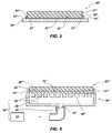
- FIG. 3 is a cross-sectional representation of an embodiment of a subpad support-subpad assembly wherein the subpad support includes clamping members configured to engage recessed portions of a complementary subpad;
- FIG. 4 is a cross-sectional representation of yet another exemplary embodiment of an assembly including a subpad support and a subpad of the present invention, wherein the subpad support is configured to apply a relatively negative pressure to the backside of the subpad to secure the subpad thereto;
- FIG. 5 is a partial perspective view of an embodiment of a subpad support configured to slidingly engage a complementarily configured subpad;
- FIG. 6 is a partial top view of an embodiment of subpad support with recesses and slots configured to receive tabs protruding from the periphery of a complementarily configured subpad;
- FIGS. 7A and 7B illustrate still another embodiment of subpad support and subpad incorporating teachings of the present invention, wherein the subpad support includes keyhole-shaped recesses configured to receive headed studs protruding from the backing of the subpad;
- FIGS. 8 and 8A are schematic representations of a belt format polishing apparatus incorporating teachings of the present invention, depicting at least partial movement of the polishing pad thereof away from the subpad support thereof;
- FIGS. 9 and 9A are schematic representations of a belt format polishing apparatus incorporating teachings of the present invention, depicting movement of the polishing pad thereof away from the subpad support thereof.
- Subpad support 10 includes a supporting surface 12 and a retention element 14 .
- Supporting surface 12 is configured to engage a backing 22 of a subpad 20 .
- Retention element 14 is configured to secure subpad 20 to subpad support 10 .
- Subpad support 10 may also include one or more lips 16 protruding therefrom and positioned so as to facilitate the alignment of subpad 20 with subpad support 10 during assembly thereof or to at least partially prevent lateral movement of subpad 20 relative to supporting surface 12 during use.
- Retention element 14 is configured to mechanically engage a corresponding, complementary structure of a known type, such as the illustrated threaded locking element 24 , on backing 22 of subpad 20 .
- a corresponding, complementary structure of a known type such as the illustrated threaded locking element 24
- retention element 14 and locking element 24 interlock so as to secure subpad 20 to subpad support 10 .
- locking element 24 is secured to a backing 22 of subpad 20 by known means, such as with a suitable adhesive.
- locking element 24 may be integral with backing 22 .
- Backing 22 may be formed from a relatively denser region of the same material as the remainder of subpad 20 , which may be formed from a material such as closed-cell polyurethane foam, and may be integral therewith, or may comprise a separate element secured to the remainder, or contact surface 23 , of subpad 20 .
- backing 22 may be formed from another polymer (e.g., polycarbonate), a metal, a ceramic, or any other suitable material, different from the material of contact surface 23 , which cushions a wafer during polishing thereof.
- a backing 22 that is separate from the remainder of subpad 20 may be secured thereto as known in the art, such as by use of adhesives or by thermally bonding contact surface 23 of subpad 20 to backing 22 thereof.
- Subpad support 10 ′ includes a supporting surface 12 ′ and a retention element 14 ′.
- supporting surface 12 ′ is configured to engage a backing 22 ′ of a subpad 20 ′ to be assembled with subpad support 10 ′.
- retention element 14 ′ is configured to mechanically secure a subpad 20 ′ to subpad support 10 ′.
- Retention element 14 ′ of subpad support 10 ′ includes a clamping member 15 ′ that is configured to be positioned around the periphery 21 ′ of at least a rigid backing 22 ′ of subpad 20 ′ upon assembly of subpad 20 ′ with subpad support 10 ′ and to be biased against periphery 21 ′ so as to secure backing 22 ′ against supporting surface 12 ′ while substantially maintaining the planarity of contact surface 23 ′ of subpad 20 ′ and, thus, the planarity of an area of a polishing pad to be supported by subpad 20 ′.
- clamping member 15 ′ at least partially prevents lateral movement of subpad 20 ′ relative to supporting surface 12 ′.
- subpad 20 ′ includes a cushioning contact surface 23 ′ and a substantially rigid backing 22 ′.
- Backing 22 ′ may be formed from a dense region of the same material as contact surface 23 ′ or from another material, such as another polymer, a metal, a ceramic, or another suitable material. If backing 22 ′ is formed from the same material as contact surface 23 ′, backing 22 ′ may be integral with contact surface 23 ′ or a separate element that is secured to contact surface 23 ′. Of course, if another material is used to form backing 22 ′, backing 22 ′ is secured to contact surface 23 ′.
- Backing 22 ′ and contact surface 23 ′ of subpad 20 ′ may be secured to one another by known means, such as by use of a suitable adhesive material or by thermally bonding backing 22 ′ and contact surface 23 ′ to one another.
- Subpad support 10 ′′ includes a supporting surface 12 ′′ that is configured to engage a backing 22 ′′ of a subpad 20 ′′.
- Subpad support 10 ′′ also includes retention elements 14 ′′ that are configured to clamp onto corresponding receptacles 26 ′′ recessed in periphery 21 ′′ of subpad 20 ′′.
- backing 22 ′′ of subpad 20 ′′ is held against supporting surface 12 ′′ of subpad support 10 ′′.
- FIG. 4 illustrates yet another embodiment of a subpad support 10 ′′′ incorporating teachings of the prevent intention.
- subpad support 10 ′′′ includes a supporting surface 12 ′′′ and a retention element 14 ′′′.
- Subpad support 10 ′′′ may also include one or more columns 16 ′′′, lips, or other structures protruding from supporting surface 12 ′′′.
- Columns 16 ′′′ are preferably configured so as to laterally surround a periphery 21 ′′′ of subpad 20 ′′′ upon assembly thereof with subpad support 10 ′′′.
- Columns 16 ′′′ are configured to align a subpad 20 ′′′ with subpad support 10 ′′′, to substantially laterally surround a subpad 20 ′′′ assembled with subpad support 10 ′′′, or to at least substantially inhibit subpad 20 ′′′ from moving laterally relative to supporting surface 12 ′′′.
- Supporting surface 12 ′′′ is configured to engage a backing 22 ′′′ of a subpad 20 ′′′ upon assembly of subpad 20 ′′′ with subpad support 10 ′′′.
- Retention element 14 ′′′ employs a negative pressure to secure a subpad 20 ′′′ to subpad support 10 ′′′.
- Retention element 14 ′′′ includes one or more apertures 30 formed through subpad support 10 ′′′ from supporting surface 12 ′′′ to an opposite surface 18 ′′′. Apertures 30 communicate with a negative pressure, or vacuum, source 34 by way of a negative pressure conduit 32 between apertures 30 and negative pressure source 34 .
- retention element 14 ′′′ also includes a chamber 35 formed within subpad support 10 ′′′ and communicating with each aperture 30 . In turn, chamber 35 communicates with conduit 32 by way of a connection port 37 on subpad support 10 ′′′.
- each aperture 30 of a retention element 14 ′′′ incorporating teachings of the present invention may communicate with negative pressure source 34 by way of separate conduits 32 .
- retention element 14 ′′′ secures a subpad 20 ′′′ to supporting surface 12 ′′′ of subpad support 10 ′′′ by applying a negative pressure to backing 22 ′′′ of subpad 20 ′′′ through apertures 30 formed in subpad support 10 ′′′.
- Subpad support 110 configured to receive a rectangular subpad 120 is illustrated.
- Subpad support 110 includes a recessed retention element 114 that is continuous with at least one end of subpad support 110 .
- Retention element 114 includes elongated retention slots 115 at opposite sides thereof.
- Retention slots 115 are configured to engage corresponding, opposite ends of a complementarily configured subpad 120 upon sliding subpad 120 in the direction of arrow A to position backing 122 of subpad 120 in substantial contact with supporting surface 112 of subpad support 110 and to effect engagement of subpad 120 by retention element 114 .
- retention slots 115 may extend laterally beneath a supporting surface 112 of subpad support 110 so as to engage thin or tapered edges 125 of subpad 120 .
- a subpad support 110 ′ may include a subpad receptacle 115 ′ formed in a supporting surface 112 ′ of subpad support 110 ′ and configured to receive at least a backing (not shown) of a complementarily configured subpad 120 ′.
- retention elements 114 ′ are disposed around the periphery 116 ′ of receptacle 115 ′ and include recesses 114 a ′ and slots 114 b ′ that are continuous with receptacle 115 ′.
- Recesses 114 a ′ are formed in supporting surface 112 ′ and, upon introduction of the backing of subpad 120 ′ into receptacle 115 ′, are configured to receive tabs 128 ′ that protrude laterally from periphery 121 ′ of subpad 120 ′, in a plane substantially parallel to the plane of subpad 120 ′, and are located proximate the backing of subpad 120 ′.
- Retention elements 114 ′ also include slots 114 b ′ that are continuous with recesses 114 a ′ and that underlie supporting surface 112 ′.
- Subpad support 110 ′′ includes a supporting surface 112 ′′ with a series of keyhole-shaped retention elements 114 ′′ formed therein.
- Retention elements 114 ′′ include an enlarged end 114 a ′′ and a narrower, elongated slot 114 b ′′ formed through and continuous with supporting surface 112 ′′, as well as a receptacle 114 c ′′ underlying supporting surface 112 ′′, enlarged end 114 a ′′, and elongated slot 114 b ′′.
- Enlarged end 114 a ′′ of each retention element 114 ′′ is configured to receive a head 128 a ′′ of a corresponding retention stud 128 ′′ that protrudes from a backing 122 ′′ of subpad 120 ′′.
- Slot 114 b ′′ is narrower than end 114 a ′′ and is configured to receive a neck 128 b ′′ of retention stud 128 ′′ as head 128 a ′′ is positioned within the portion of receptacle 114 c ′′ that underlies slot 114 b ′′. As shown in FIGS.
- retention elements 114 ′′ may be slightly curved so as to facilitate engagement of a subpad 120 ′′ by subpad support 110 ′′ upon slight rotation of subpad 120 ′′ in the direction of arrow C relative to subpad support 110 ′′.
- slot 114 b ′′ and receptacle 114 c ′′ of a retention element 114 ′′ may be angled so as to facilitate the retention of a complementary retention stud 128 ′′ therein.
- subpad support 10 may be included in a web format polishing apparatus 40 , illustrated in FIGS. 8 and 8A , or in a belt-type polishing apparatus 40 ′, shown in FIGS. 9 and 9A .
- polishing apparatus 40 is positioned adjacent a web format polishing pad, which is referred to herein and known in the art as a “web” 42 .
- Polishing apparatus 40 also includes a supply reel 44 from which fresh portions of web 42 are supplied, as well as a take-up reel 46 , which receives previously used portions of web 42 .
- a semiconductor device structure 1 is brought into frictional contact with web 42 , on an opposite side thereof from subpad support 10 .
- the portion of web 42 that is being used to polish semiconductor device structure 1 is supported from beneath by a subpad 20 assembled with subpad support 10 .
- Polishing apparatus 40 includes a polishing pad movement element 50 , which is also referred to herein as a subpad access element, to effect the movement of web 42 at least partially away from subpad 20 so as to avoid physical contact of an operator with web 42 while facilitating access to a worn or damaged subpad 20 .
- polishing pad movement element 50 is associated with at least one of supply reel 44 and take-up reel 46 of polishing apparatus 40 .
- Polishing pad movement element 50 preferably effects the movement of web 42 away from subpad support 10 in a controlled manner and at a controlled rate to minimize stress on web 42 .
- polishing pad movement element 50 examples include hydraulic pistons, screw drive motors, gear drive motors, and the like.
- Polishing apparatus 40 may also include a latch 52 or other known releasable locking element that is configured to prevent movement of web 42 away from subpad 20 and subpad support 10 when such movement is not desired.
- end 42 b may be pivotally connected to apparatus 40 , such as by a pivot pin 54 ′ that connects one conveyor support 48 to a fixed structure of apparatus 40 or otherwise, as known in the art (see FIGS. 9 and 9A ).
- polishing apparatus 40 ′ includes a belt format polishing pad, which is referred to herein and known in the art as a “belt” 42 ′.
- Belt 42 ′ may be continually moved around conveyor supports 48 to supply fresh or newly conditioned portions of belt 42 ′ for use in polishing a semiconductor device structure 1 .
- the portion of belt 42 ′ that is being used to polish semiconductor device structure 1 is supported from beneath by a subpad 20 assembled with subpad support 10 .
- polishing apparatus 40 ′ is supplied with a polishing pad movement element 50 ′ that effects the movement of belt 42 ′ at least partially away from subpad 20 .
- polishing pad movement element 50 ′ is associated with at least one conveyor support 48 of polishing apparatus 40 ′. Polishing pad movement element 50 ′ preferably effects the movement of belt 42 ′ away from subpad support 10 in a controlled manner and at a controlled rate.
- polishing pad movement element 50 ′ examples include hydraulic cylinders, pneumatic cylinders, screw drive motors, gear drive motors, and the like.
- Polishing apparatus 40 ′ may also include a latch 52 ′ configured to prevent movement of belt 42 ′ away from subpad 20 and subpad support 10 when such movement is not desired.
- end 42 b ′ may be pivotally connected to apparatus 40 ′, such as by a pivot pin 54 ′ that connects one conveyor support 48 to a fixed structure of apparatus 40 ′ or otherwise, as known in the art.
- Latch 52 ′ of polishing apparatus 40 ′ is positioned so as to facilitate the movement of end 42 a ′ of belt 42 ′ while end 42 b ′ of belt 42 ′ pivots around pivot pin 54 ′, thereby at least partially moving belt 42 ′ away from subpad 20 and subpad support 10 so as to facilitate access to subpad 20 .
- Belt 42 ′ is then at least partially moved away from subpad 20 and subpad support 10 with the assistance of or by way of polishing pad movement element 50 ′.
- apparatus 40 ′ could be configured such that both ends 42 a ′, 42 b ′ of belt 42 ′ may be moved so as to effect movement of belt 42 ′ away from subpad support 10 .
- subpad 20 is released by retention element 14 (see, e.g., FIGS. 1-3 ) and disassembled from subpad support 10 .
- Another subpad 20 may be assembled with subpad support 10 and secured thereto by retention element 14 .
- Belt 42 ′ may then be repositioned adjacent subpad 20 and subpad support 10 with the assistance or by way of polishing pad movement element 50 ′.
- Latch 52 ′ may be repositioned so as to secure belt 42 ′ in place.
Abstract
Description
Claims (16)
Priority Applications (1)
| Application Number | Priority Date | Filing Date | Title |
|---|---|---|---|
| US10/310,256 US7591061B2 (en) | 2000-08-31 | 2002-12-04 | Method for securing a subpad to a subpad support |
Applications Claiming Priority (2)
| Application Number | Priority Date | Filing Date | Title |
|---|---|---|---|
| US09/652,878 US7077733B1 (en) | 2000-08-31 | 2000-08-31 | Subpad support with a releasable subpad securing element and polishing apparatus including the subpad support |
| US10/310,256 US7591061B2 (en) | 2000-08-31 | 2002-12-04 | Method for securing a subpad to a subpad support |
Related Parent Applications (1)
| Application Number | Title | Priority Date | Filing Date |
|---|---|---|---|
| US09/652,878 Division US7077733B1 (en) | 2000-08-31 | 2000-08-31 | Subpad support with a releasable subpad securing element and polishing apparatus including the subpad support |
Publications (2)
| Publication Number | Publication Date |
|---|---|
| US20040072502A1 US20040072502A1 (en) | 2004-04-15 |
| US7591061B2 true US7591061B2 (en) | 2009-09-22 |
Family
ID=24618561
Family Applications (4)
| Application Number | Title | Priority Date | Filing Date |
|---|---|---|---|
| US09/652,878 Expired - Lifetime US7077733B1 (en) | 2000-08-31 | 2000-08-31 | Subpad support with a releasable subpad securing element and polishing apparatus including the subpad support |
| US10/310,256 Expired - Fee Related US7591061B2 (en) | 2000-08-31 | 2002-12-04 | Method for securing a subpad to a subpad support |
| US10/310,721 Expired - Fee Related US7377018B2 (en) | 2000-08-31 | 2002-12-04 | Method of replacing a subpad of a polishing apparatus |
| US11/398,834 Expired - Fee Related US7361078B2 (en) | 2000-08-31 | 2006-04-06 | Subpad support with releasable subpad securing element and polishing apparatus |
Family Applications Before (1)
| Application Number | Title | Priority Date | Filing Date |
|---|---|---|---|
| US09/652,878 Expired - Lifetime US7077733B1 (en) | 2000-08-31 | 2000-08-31 | Subpad support with a releasable subpad securing element and polishing apparatus including the subpad support |
Family Applications After (2)
| Application Number | Title | Priority Date | Filing Date |
|---|---|---|---|
| US10/310,721 Expired - Fee Related US7377018B2 (en) | 2000-08-31 | 2002-12-04 | Method of replacing a subpad of a polishing apparatus |
| US11/398,834 Expired - Fee Related US7361078B2 (en) | 2000-08-31 | 2006-04-06 | Subpad support with releasable subpad securing element and polishing apparatus |
Country Status (1)
| Country | Link |
|---|---|
| US (4) | US7077733B1 (en) |
Cited By (1)
| Publication number | Priority date | Publication date | Assignee | Title |
|---|---|---|---|---|
| US20080274679A1 (en) * | 2007-05-04 | 2008-11-06 | Lg Electronics Inc. | Sheet metal finished by continuous hair-line on its plane and curved surface and apparatus and method for finishing by continuous hair-line on the same |
Families Citing this family (9)
| Publication number | Priority date | Publication date | Assignee | Title |
|---|---|---|---|---|
| US7048615B2 (en) * | 2004-08-05 | 2006-05-23 | United Microelectronics Corp. | Pad backer and CMP process using the same |
| US6921324B1 (en) * | 2004-08-05 | 2005-07-26 | United Microelectronics Corp. | Pad backer |
| TWI303595B (en) * | 2006-11-24 | 2008-12-01 | Univ Nat Taiwan Science Tech | Polishing apparatus and pad replacing method thereof |
| US7820005B2 (en) * | 2008-07-18 | 2010-10-26 | Rohm And Haas Electronic Materials Cmp Holdings, Inc. | Multilayer chemical mechanical polishing pad manufacturing process |
| US7645186B1 (en) * | 2008-07-18 | 2010-01-12 | Rohm And Haas Electronic Materials Cmp Holdings, Inc. | Chemical mechanical polishing pad manufacturing assembly |
| US20100099342A1 (en) * | 2008-10-21 | 2010-04-22 | Applied Materials, Inc. | Pad conditioner auto disk change |
| US9457447B2 (en) | 2011-03-28 | 2016-10-04 | Ebara Corporation | Polishing apparatus and polishing method |
| CN102756340B (en) * | 2011-04-29 | 2015-04-22 | 中芯国际集成电路制造(上海)有限公司 | Chemical mechanical polishing machine and polishing pad part thereof |
| JP6920849B2 (en) * | 2017-03-27 | 2021-08-18 | 株式会社荏原製作所 | Substrate processing method and equipment |
Citations (22)
| Publication number | Priority date | Publication date | Assignee | Title |
|---|---|---|---|---|
| US3813825A (en) * | 1969-09-30 | 1974-06-04 | Alliance Tool And Die Corp | Polishing machine or the like with a removable platen |
| US5593344A (en) * | 1994-10-11 | 1997-01-14 | Ontrak Systems, Inc. | Wafer polishing machine with fluid bearings and drive systems |
| US5704827A (en) | 1994-10-19 | 1998-01-06 | Ebara Corporation | Polishing apparatus including cloth cartridge connected to turntable |
| US5722877A (en) | 1996-10-11 | 1998-03-03 | Lam Research Corporation | Technique for improving within-wafer non-uniformity of material removal for performing CMP |
| US5810964A (en) | 1995-12-06 | 1998-09-22 | Nec Corporation | Chemical mechanical polishing device for a semiconductor wafer |
| US5871390A (en) | 1997-02-06 | 1999-02-16 | Lam Research Corporation | Method and apparatus for aligning and tensioning a pad/belt used in linear planarization for chemical mechanical polishing |
| US5921852A (en) | 1996-06-21 | 1999-07-13 | Ebara Corporation | Polishing apparatus having a cloth cartridge |
| US5931724A (en) * | 1997-07-11 | 1999-08-03 | Applied Materials, Inc. | Mechanical fastener to hold a polishing pad on a platen in a chemical mechanical polishing system |
| US5980368A (en) | 1997-11-05 | 1999-11-09 | Aplex Group | Polishing tool having a sealed fluid chamber for support of polishing pad |
| US6033293A (en) | 1997-10-08 | 2000-03-07 | Lucent Technologies Inc. | Apparatus for performing chemical-mechanical polishing |
| US6059643A (en) | 1997-02-21 | 2000-05-09 | Aplex, Inc. | Apparatus and method for polishing a flat surface using a belted polishing pad |
| US6083083A (en) | 1994-04-22 | 2000-07-04 | Kabushiki Kaisha Toshiba | Separation type grinding surface plate and grinding apparatus using same |
| US6126527A (en) | 1998-07-10 | 2000-10-03 | Aplex Inc. | Seal for polishing belt center support having a single movable sealed cavity |
| US6135859A (en) * | 1999-04-30 | 2000-10-24 | Applied Materials, Inc. | Chemical mechanical polishing with a polishing sheet and a support sheet |
| US6220942B1 (en) * | 1999-04-02 | 2001-04-24 | Applied Materials, Inc. | CMP platen with patterned surface |
| US6224474B1 (en) | 1999-01-06 | 2001-05-01 | Buehler, Ltd. | Magnetic disc system for grinding or polishing specimens |
| US6244944B1 (en) * | 1999-08-31 | 2001-06-12 | Micron Technology, Inc. | Method and apparatus for supporting and cleaning a polishing pad for chemical-mechanical planarization of microelectronic substrates |
| US6273800B1 (en) | 1999-08-31 | 2001-08-14 | Micron Technology, Inc. | Method and apparatus for supporting a polishing pad during chemical-mechanical planarization of microelectronic substrates |
| US6296557B1 (en) | 1999-04-02 | 2001-10-02 | Micron Technology, Inc. | Method and apparatus for releasably attaching polishing pads to planarizing machines in mechanical and/or chemical-mechanical planarization of microelectronic-device substrate assemblies |
| US6394887B1 (en) | 1999-04-19 | 2002-05-28 | Stillman Eugene Edinger | Apparatus for use with automated abrading equipment |
| US6439967B2 (en) * | 1998-09-01 | 2002-08-27 | Micron Technology, Inc. | Microelectronic substrate assembly planarizing machines and methods of mechanical and chemical-mechanical planarization of microelectronic substrate assemblies |
| US6602380B1 (en) | 1998-10-28 | 2003-08-05 | Micron Technology, Inc. | Method and apparatus for releasably attaching a polishing pad to a chemical-mechanical planarization machine |
-
2000
- 2000-08-31 US US09/652,878 patent/US7077733B1/en not_active Expired - Lifetime
-
2002
- 2002-12-04 US US10/310,256 patent/US7591061B2/en not_active Expired - Fee Related
- 2002-12-04 US US10/310,721 patent/US7377018B2/en not_active Expired - Fee Related
-
2006
- 2006-04-06 US US11/398,834 patent/US7361078B2/en not_active Expired - Fee Related
Patent Citations (23)
| Publication number | Priority date | Publication date | Assignee | Title |
|---|---|---|---|---|
| US3813825A (en) * | 1969-09-30 | 1974-06-04 | Alliance Tool And Die Corp | Polishing machine or the like with a removable platen |
| US6083083A (en) | 1994-04-22 | 2000-07-04 | Kabushiki Kaisha Toshiba | Separation type grinding surface plate and grinding apparatus using same |
| US5593344A (en) * | 1994-10-11 | 1997-01-14 | Ontrak Systems, Inc. | Wafer polishing machine with fluid bearings and drive systems |
| US5704827A (en) | 1994-10-19 | 1998-01-06 | Ebara Corporation | Polishing apparatus including cloth cartridge connected to turntable |
| US5810964A (en) | 1995-12-06 | 1998-09-22 | Nec Corporation | Chemical mechanical polishing device for a semiconductor wafer |
| US5921852A (en) | 1996-06-21 | 1999-07-13 | Ebara Corporation | Polishing apparatus having a cloth cartridge |
| US5722877A (en) | 1996-10-11 | 1998-03-03 | Lam Research Corporation | Technique for improving within-wafer non-uniformity of material removal for performing CMP |
| US5871390A (en) | 1997-02-06 | 1999-02-16 | Lam Research Corporation | Method and apparatus for aligning and tensioning a pad/belt used in linear planarization for chemical mechanical polishing |
| US6059643A (en) | 1997-02-21 | 2000-05-09 | Aplex, Inc. | Apparatus and method for polishing a flat surface using a belted polishing pad |
| US5931724A (en) * | 1997-07-11 | 1999-08-03 | Applied Materials, Inc. | Mechanical fastener to hold a polishing pad on a platen in a chemical mechanical polishing system |
| US6033293A (en) | 1997-10-08 | 2000-03-07 | Lucent Technologies Inc. | Apparatus for performing chemical-mechanical polishing |
| US5980368A (en) | 1997-11-05 | 1999-11-09 | Aplex Group | Polishing tool having a sealed fluid chamber for support of polishing pad |
| US6126527A (en) | 1998-07-10 | 2000-10-03 | Aplex Inc. | Seal for polishing belt center support having a single movable sealed cavity |
| US6439967B2 (en) * | 1998-09-01 | 2002-08-27 | Micron Technology, Inc. | Microelectronic substrate assembly planarizing machines and methods of mechanical and chemical-mechanical planarization of microelectronic substrate assemblies |
| US6602380B1 (en) | 1998-10-28 | 2003-08-05 | Micron Technology, Inc. | Method and apparatus for releasably attaching a polishing pad to a chemical-mechanical planarization machine |
| US6224474B1 (en) | 1999-01-06 | 2001-05-01 | Buehler, Ltd. | Magnetic disc system for grinding or polishing specimens |
| US6296557B1 (en) | 1999-04-02 | 2001-10-02 | Micron Technology, Inc. | Method and apparatus for releasably attaching polishing pads to planarizing machines in mechanical and/or chemical-mechanical planarization of microelectronic-device substrate assemblies |
| US6220942B1 (en) * | 1999-04-02 | 2001-04-24 | Applied Materials, Inc. | CMP platen with patterned surface |
| US6394887B1 (en) | 1999-04-19 | 2002-05-28 | Stillman Eugene Edinger | Apparatus for use with automated abrading equipment |
| US6135859A (en) * | 1999-04-30 | 2000-10-24 | Applied Materials, Inc. | Chemical mechanical polishing with a polishing sheet and a support sheet |
| US6244944B1 (en) * | 1999-08-31 | 2001-06-12 | Micron Technology, Inc. | Method and apparatus for supporting and cleaning a polishing pad for chemical-mechanical planarization of microelectronic substrates |
| US6273800B1 (en) | 1999-08-31 | 2001-08-14 | Micron Technology, Inc. | Method and apparatus for supporting a polishing pad during chemical-mechanical planarization of microelectronic substrates |
| US6331139B2 (en) | 1999-08-31 | 2001-12-18 | Micron Technology, Inc. | Method and apparatus for supporting a polishing pad during chemical-mechanical planarization of microelectronic substrates |
Cited By (2)
| Publication number | Priority date | Publication date | Assignee | Title |
|---|---|---|---|---|
| US20080274679A1 (en) * | 2007-05-04 | 2008-11-06 | Lg Electronics Inc. | Sheet metal finished by continuous hair-line on its plane and curved surface and apparatus and method for finishing by continuous hair-line on the same |
| US8192253B2 (en) * | 2007-05-04 | 2012-06-05 | Lg Electronics Inc. | Finishing apparatus |
Also Published As
| Publication number | Publication date |
|---|---|
| US20030110609A1 (en) | 2003-06-19 |
| US7361078B2 (en) | 2008-04-22 |
| US7077733B1 (en) | 2006-07-18 |
| US7377018B2 (en) | 2008-05-27 |
| US20060178096A1 (en) | 2006-08-10 |
| US20040072502A1 (en) | 2004-04-15 |
Similar Documents
| Publication | Publication Date | Title |
|---|---|---|
| US7361078B2 (en) | Subpad support with releasable subpad securing element and polishing apparatus | |
| US6932672B2 (en) | Apparatus for in-situ optical endpointing on web-format planarizing machines in mechanical or chemical-mechanical planarization of microelectronic-device substrate assemblies and methods for making and using same | |
| US6302767B1 (en) | Chemical mechanical polishing with a polishing sheet and a support sheet | |
| US6729944B2 (en) | Chemical mechanical polishing apparatus with rotating belt | |
| JP4128343B2 (en) | Wafer notch polishing machine and wafer orientation notch polishing method | |
| US20140237905A1 (en) | Method of forming polishing sheet | |
| JP2002524281A (en) | Carrier head for chemical mechanical polishing of substrates | |
| JP2001205549A (en) | One side polishing method and device for substrate edge portion | |
| US6419559B1 (en) | Using a purge gas in a chemical mechanical polishing apparatus with an incrementally advanceable polishing sheet | |
| US6309278B1 (en) | Method and apparatus for polishing optical connector end faces | |
| US7210985B2 (en) | Shaped polishing pads for beveling microfeature workpiece edges, and associated systems and methods | |
| KR101411293B1 (en) | Polishing head, polishing apparatus and work removing method | |
| EP1025955B1 (en) | Chemical mechanical polishing with a moving polishing sheet | |
| US6520841B2 (en) | Apparatus and methods for chemical mechanical polishing with an incrementally advanceable polishing sheet | |
| US7156933B2 (en) | Configuration and method for mounting a backing film to a polish head | |
| JPH10244455A (en) | Glass substrate smoothing device | |
| JPH07276218A (en) | Wire type cutting device | |
| JPS59172110A (en) | Head grinding device | |
| JPH10217239A (en) | Slicing method and wire sawing device | |
| JP3179373B2 (en) | Rollers for processing wire saws | |
| KR20100094466A (en) | Polishing head and polishing apparatus | |
| JP4719966B2 (en) | Tamaki hoisting device | |
| JP2914099B2 (en) | Polishing device for elastic roll | |
| JP4176562B2 (en) | Wafer edge polishing equipment | |
| US3029180A (en) | Splicing of ribbon rubber thread |
Legal Events
| Date | Code | Title | Description |
|---|---|---|---|
| FEPP | Fee payment procedure |
Free format text: PAYOR NUMBER ASSIGNED (ORIGINAL EVENT CODE: ASPN); ENTITY STATUS OF PATENT OWNER: LARGE ENTITY |
|
| FPAY | Fee payment |
Year of fee payment: 4 |
|
| AS | Assignment |
Owner name: U.S. BANK NATIONAL ASSOCIATION, AS COLLATERAL AGENT, CALIFORNIA Free format text: SECURITY INTEREST;ASSIGNOR:MICRON TECHNOLOGY, INC.;REEL/FRAME:038669/0001 Effective date: 20160426 Owner name: U.S. BANK NATIONAL ASSOCIATION, AS COLLATERAL AGEN Free format text: SECURITY INTEREST;ASSIGNOR:MICRON TECHNOLOGY, INC.;REEL/FRAME:038669/0001 Effective date: 20160426 |
|
| AS | Assignment |
Owner name: MORGAN STANLEY SENIOR FUNDING, INC., AS COLLATERAL AGENT, MARYLAND Free format text: PATENT SECURITY AGREEMENT;ASSIGNOR:MICRON TECHNOLOGY, INC.;REEL/FRAME:038954/0001 Effective date: 20160426 Owner name: MORGAN STANLEY SENIOR FUNDING, INC., AS COLLATERAL Free format text: PATENT SECURITY AGREEMENT;ASSIGNOR:MICRON TECHNOLOGY, INC.;REEL/FRAME:038954/0001 Effective date: 20160426 |
|
| REMI | Maintenance fee reminder mailed | ||
| AS | Assignment |
Owner name: U.S. BANK NATIONAL ASSOCIATION, AS COLLATERAL AGENT, CALIFORNIA Free format text: CORRECTIVE ASSIGNMENT TO CORRECT THE REPLACE ERRONEOUSLY FILED PATENT #7358718 WITH THE CORRECT PATENT #7358178 PREVIOUSLY RECORDED ON REEL 038669 FRAME 0001. ASSIGNOR(S) HEREBY CONFIRMS THE SECURITY INTEREST;ASSIGNOR:MICRON TECHNOLOGY, INC.;REEL/FRAME:043079/0001 Effective date: 20160426 Owner name: U.S. BANK NATIONAL ASSOCIATION, AS COLLATERAL AGEN Free format text: CORRECTIVE ASSIGNMENT TO CORRECT THE REPLACE ERRONEOUSLY FILED PATENT #7358718 WITH THE CORRECT PATENT #7358178 PREVIOUSLY RECORDED ON REEL 038669 FRAME 0001. ASSIGNOR(S) HEREBY CONFIRMS THE SECURITY INTEREST;ASSIGNOR:MICRON TECHNOLOGY, INC.;REEL/FRAME:043079/0001 Effective date: 20160426 |
|
| LAPS | Lapse for failure to pay maintenance fees |
Free format text: PATENT EXPIRED FOR FAILURE TO PAY MAINTENANCE FEES (ORIGINAL EVENT CODE: EXP.) |
|
| STCH | Information on status: patent discontinuation |
Free format text: PATENT EXPIRED DUE TO NONPAYMENT OF MAINTENANCE FEES UNDER 37 CFR 1.362 |
|
| FP | Lapsed due to failure to pay maintenance fee |
Effective date: 20170922 |
|
| AS | Assignment |
Owner name: MICRON TECHNOLOGY, INC., IDAHO Free format text: RELEASE BY SECURED PARTY;ASSIGNOR:U.S. BANK NATIONAL ASSOCIATION, AS COLLATERAL AGENT;REEL/FRAME:047243/0001 Effective date: 20180629 |
|
| AS | Assignment |
Owner name: MICRON TECHNOLOGY, INC., IDAHO Free format text: RELEASE BY SECURED PARTY;ASSIGNOR:MORGAN STANLEY SENIOR FUNDING, INC., AS COLLATERAL AGENT;REEL/FRAME:050937/0001 Effective date: 20190731 |