US7583316B2 - Digital camera and mobile telephone having digital camera - Google Patents
Digital camera and mobile telephone having digital camera Download PDFInfo
- Publication number
- US7583316B2 US7583316B2 US10/532,399 US53239905A US7583316B2 US 7583316 B2 US7583316 B2 US 7583316B2 US 53239905 A US53239905 A US 53239905A US 7583316 B2 US7583316 B2 US 7583316B2
- Authority
- US
- United States
- Prior art keywords
- camera
- digital camera
- portable telephone
- user
- image
- Prior art date
- Legal status (The legal status is an assumption and is not a legal conclusion. Google has not performed a legal analysis and makes no representation as to the accuracy of the status listed.)
- Expired - Fee Related, expires
Links
Images


Classifications
-
- H—ELECTRICITY
- H04—ELECTRIC COMMUNICATION TECHNIQUE
- H04N—PICTORIAL COMMUNICATION, e.g. TELEVISION
- H04N23/00—Cameras or camera modules comprising electronic image sensors; Control thereof
-
- H—ELECTRICITY
- H04—ELECTRIC COMMUNICATION TECHNIQUE
- H04B—TRANSMISSION
- H04B1/00—Details of transmission systems, not covered by a single one of groups H04B3/00 - H04B13/00; Details of transmission systems not characterised by the medium used for transmission
-
- H—ELECTRICITY
- H04—ELECTRIC COMMUNICATION TECHNIQUE
- H04M—TELEPHONIC COMMUNICATION
- H04M1/00—Substation equipment, e.g. for use by subscribers
-
- H—ELECTRICITY
- H04—ELECTRIC COMMUNICATION TECHNIQUE
- H04N—PICTORIAL COMMUNICATION, e.g. TELEVISION
- H04N23/00—Cameras or camera modules comprising electronic image sensors; Control thereof
- H04N23/45—Cameras or camera modules comprising electronic image sensors; Control thereof for generating image signals from two or more image sensors being of different type or operating in different modes, e.g. with a CMOS sensor for moving images in combination with a charge-coupled device [CCD] for still images
-
- H—ELECTRICITY
- H04—ELECTRIC COMMUNICATION TECHNIQUE
- H04N—PICTORIAL COMMUNICATION, e.g. TELEVISION
- H04N23/00—Cameras or camera modules comprising electronic image sensors; Control thereof
- H04N23/50—Constructional details
- H04N23/51—Housings
-
- H—ELECTRICITY
- H04—ELECTRIC COMMUNICATION TECHNIQUE
- H04N—PICTORIAL COMMUNICATION, e.g. TELEVISION
- H04N23/00—Cameras or camera modules comprising electronic image sensors; Control thereof
- H04N23/60—Control of cameras or camera modules
- H04N23/63—Control of cameras or camera modules by using electronic viewfinders
-
- H—ELECTRICITY
- H04—ELECTRIC COMMUNICATION TECHNIQUE
- H04N—PICTORIAL COMMUNICATION, e.g. TELEVISION
- H04N23/00—Cameras or camera modules comprising electronic image sensors; Control thereof
- H04N23/60—Control of cameras or camera modules
- H04N23/66—Remote control of cameras or camera parts, e.g. by remote control devices
-
- H—ELECTRICITY
- H04—ELECTRIC COMMUNICATION TECHNIQUE
- H04M—TELEPHONIC COMMUNICATION
- H04M2250/00—Details of telephonic subscriber devices
- H04M2250/16—Details of telephonic subscriber devices including more than one display unit
-
- H—ELECTRICITY
- H04—ELECTRIC COMMUNICATION TECHNIQUE
- H04N—PICTORIAL COMMUNICATION, e.g. TELEVISION
- H04N7/00—Television systems
- H04N7/14—Systems for two-way working
- H04N7/141—Systems for two-way working between two video terminals, e.g. videophone
- H04N7/142—Constructional details of the terminal equipment, e.g. arrangements of the camera and the display
- H04N2007/145—Handheld terminals
Definitions
- the present invention relates to a digital camera and a portable telephone equipped with a digital camera on which a digital camera is mounted.
- a recent digital camera has been progressively miniaturized and a portable telephone on which the digital camera is mounted to photograph the face of a user or the landscape in a neighborhood has been put to practical use. Further, to photograph both a front side and an opposite side, a method that one digital camera mounted on the portable telephone is rotated or detachably attached to the portable telephone to change its direction has been known (for instance, see Patent Document 1). However, most of the portable telephones that have been used have the cameras fixed on either the front sides or the opposite sides.
- FIG. 16 shows a schematic sectional view of a usual portable telephone 200 with a digital camera.
- the portable telephone 200 with the digital camera supports a second casing member 214 at the hinge 213 of an end of an arm extending from a first casing member 212 so as to freely open and close.
- a magnet 222 for detecting opening and closing operations To the second casing member 214 , a magnet 222 for detecting opening and closing operations, a receiver 224 , a liquid crystal display device 201 viewed by an operator when the second casing member 214 is opened, a back light 209 for the liquid crystal display device 201 and a camera 230 are attached.
- the camera 230 is arranged so that while the user (not shown in the drawing) of the portable telephone 200 holds the portable telephone, the user can photograph the face or the user can recognize a monitor image on the liquid crystal display device 201 .
- the liquid crystal display device 201 is driven by a driver circuit 241 .
- the liquid crystal display device 201 , the back light 209 , the receiver 224 and the camera 230 are respectively connected to a flexible controlling board 216 having a branching end.
- the other end of the flexible controlling board 216 is connected to a main body board 215 in the first casing member 212 .
- the main body board 215 of the portable telephone is provided in the first casing member 212 .
- the respective circuits of a control part 218 , a memory 219 and a radio part 220 , a key operating part 217 , a microphone 223 and an opening and closing detecting unit 221 are attached to realize a radio communication function as the portable telephone.
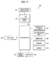
- FIG. 17 the schematic block diagram of the usual portable telephone 200 having the digital camera is shown.
- the driver circuit 241 is connected to the control part 218 and the liquid crystal display device 201 is connected to the driver circuit 241 .
- a memory part 251 for temporarily storing image information to be displayed is provided in the driver circuit 241 .
- the memory 219 in which the image information is stored the back light 209 for the liquid crystal display device 201 as a completely transmitting type liquid crystal display device, the radio part 220 for performing a radio communication, the microphone 223 for transmitting voice, the receiver 224 for receiving voice, the key operating part 217 , the opening and closing detecting unit 221 and the camera 230 are connected.
- a photographing operation carried out by the camera 230 of the usual portable telephone 200 equipped with the digital camera will be described below.
- the user of the portable telephone 200 holds the first casing member 212 and opens the second casing member 214 to input a camera mode selecting signal by using the key operating unit 217 and operate a camera mode by the control part 218 .
- the user picks up an image by an image pick-up unit of the camera 230 that is not in the drawing to display a monitor image on the liquid crystal display device 201 .
- the image photographed by the camera 230 is stored in the memory 219 and the stored image is displayed on the liquid crystal display device 201 .
- the control part 218 turns off the power of the camera 230 to complete the camera mode.
- the image stored in the memory 219 can be read and displayed on the liquid crystal display device 201 by operating the key operating unit 217 or transmitted to other portable telephone by using the radio part 220 or the photographed image can be printed by connecting the portable telephone 200 to a printer that is not shown in the drawing by a cable.
- Patent Document 1 JP-A-2001-245034 (Pages 3 to 4, FIG. 1)
- An existing ordinary digital camera has a camera on one surface of a casing member and a monitor screen on a surface opposite to the camera.
- the camera has a structure in which when the user photographs an object, the user (photographer) directs the camera to the object to be photographed and views the monitor screen in the opposite side to the camera and presses a shutter button. Accordingly, when the user holds the digital camera to photograph the face of the user himself or herself, the user turns the inside of the digital camera out. In this case, since the user himself or herself is the object to be photographed, the user cannot inconveniently view the monitor screen located in the opposite side of the camera.
- the portable telephone having the digital camera on which the digital camera is mounted even when the camera 230 and the liquid crystal display device 201 are provided on the same plane as shown in FIG. 16 , operations for turning out the portable telephone having the digital came are necessary when the face of the user is photographed and when an image located in the opposite side to the face of the user is photographed.
- the shutter button is undesirably hardly pressed down.
- a shutter chance is taken aim at once under a camera mode, however, the chance does not come so that a next shutter chance is taken aim at.
- the opening and closing detecting unit 221 detects that the second casing member 214 is closed and the control part 218 turns off the power of the camera 230 to complete the camera mode. Therefore, when the second casing member 214 is subsequently opened, the camera mode needs to be started from its setting operation so that the shutter chance is undesirably missed.
- a digital camera comprises: a first camera provided on a first surface of a casing member; a second camera provided on a second surface in the back side of the first surface of the casing member; and a camera selecting unit for selecting a photographing camera to photograph an image by selecting the photographing camera.
- the user can selectively photograph an image located in the side of the face of the user and an image located in an opposite side to the face of the user without turning out the digital camera or the portable telephone having the digital camera.
- both the first camera and the second camera are selected by the camera selecting unit to photograph images by both the first camera and the second camera at the same time.
- the image located in the side of the face of the user and the image located in the opposite side to the face of the user can be photographed at the same time.
- an image synthesizing unit is further provided for synthesizing the images photographed by the first camera and the second camera to photograph the synthesized image obtained by synthesizing the images photographed by the first camera and the second camera.
- a synthesized photograph can be obtained in which the image located in the side of the face of the user is synthesized with the image located in the opposite side to the face of the user as one image.
- a camera mode completing unit completes the camera mode.
- the opening and closing detecting unit detects that the casing member of the foldable portable telephone is opened without an input of other signal, the camera mode is operated again by the camera mode setting unit.
- the camera mode is operated, only when the casing member of the foldable portable telephone is closed, the camera mode is completed. Further, only when the casing member is directly opened, the camera mode is operated again to prevent a shutter chance from being missed.
- FIG. 1 is a schematic sectional view of a portable telephone equipped with a digital camera according to a first embodiment of the present invention
- FIG. 2 is a schematic block diagram of the portable telephone having the digital camera according to the first embodiment of the present invention
- FIG. 3 is a conceptual view showing a using state of the portable telephone having the digital camera according to the first embodiment of the present invention
- FIG. 4 is an external appearance view when the portable telephone having the digital camera according to the first embodiment of the present invention is opened;
- FIG. 5 is a conceptual view showing a using state of a portable telephone equipped with a digital camera according to a second embodiment of the present invention
- FIG. 6 is an external appearance view of the portable telephone having the digital camera according to the second embodiment of the present invention.
- FIG. 7 is an external appearance view of the portable telephone having the digital camera according to the second embodiment of the present invention.
- FIG. 8 is an external appearance view of a portable telephone equipped with a digital camera according to a third embodiment of the present invention.
- FIG. 9 is an external appearance view of the portable telephone having the digital camera according to the third embodiment of the present invention.
- FIG. 10 is a flowchart of a camera mode of a portable telephone equipped with a digital camera according to the present invention.
- FIG. 11 is a flowchart of a camera mode of a portable telephone equipped with a digital camera according to a fourth embodiment of the present invention.
- FIG. 12 is a flowchart of a camera mode of a portable telephone equipped with a digital camera according to a fifth embodiment of the present invention.
- FIG. 13 is an external appearance view of the portable telephone having the digital camera according to the fifth embodiment of the present invention.
- FIG. 14 is a schematic sectional view of a portable telephone equipped with a digital camera according to a sixth embodiment of the present invention.
- FIG. 15 is a schematic sectional view of a portable telephone equipped with a digital camera according to a seventh embodiment of the present invention.
- FIG. 16 is a schematic sectional view of a usual portable telephone equipped with a digital camera.
- FIG. 17 is a schematic block diagram of the usual portable telephone having the digital camera.
- reference numeral 1 designates a first liquid crystal display part.
- 2 designates a second liquid crystal display part.
- 3 designates a connecting flexible board.
- 4 designates a driver circuit.
- 9 designates a back light.
- 18 designates a control part.
- 19 designates a memory.
- 23 designates a first camera.
- 24 designates a second camera.
- 41 designates a memory part.
- 42 designates a display switching part.
- 212 designates a first casing member.
- 213 designates a hinge.
- 214 designates a second casing member.
- 215 designates a main body board.
- 217 designates a key operating part.
- 219 designates a memory.
- 220 designates a radio part.
- 221 designates an opening and closing detecting unit.
- 223 designates a microphone.
- 224 designates a receiver.
- 310 designates a holder.
- a digital camera includes: a first camera provided on a first surface of a casing member; a second camera provided on a second surface in the back side of the first surface of the casing member; a control unit for controlling the photographing operations of the first camera and the second camera; a camera selecting unit for selecting a photographing camera; a camera shutter unit; a monitor unit; and an image storing unit.
- the photographing camera is selected by the camera selecting unit to photograph an image.
- an image located in the side of the face of a user and an image located in an opposite side to the face of the user can be selectively photographed without turning out the digital camera.
- both the first camera and the second camera are selected by the camera selecting unit to photograph images by both the first camera and the second camera at the same time.
- an image located in the side of the face of a user and an image located in an opposite side to the face of the user can be photographed at the same time.
- an image synthesizing unit is further provided for synthesizing the images photographed by the first camera and the second camera in addition to the above-described structure to photograph the synthesized image obtained by synthesizing the images photographed by the first camera and the second camera.
- a synthesized photograph can be obtained in which the image located in the side of the face of the user is synthesized with the image located in the opposite side to the face of the user as one image.
- one screen of the monitor unit is divided into a first display area and a second display area to display all part or a part of the image photographed by the first camera in the first display area and display all part or a part of the image photographed by the second camera in the second display area.
- the images photographed by the first camera and the second camera that are displayed on the monitor unit are photographed as the synthesized image.
- all part or a part of the image photographed by the first camera can be displayed in the first display area and all part or a part of the image photographed by the second camera can be displayed in the second display area.
- the monitor unit is formed with a first liquid crystal display part and a second liquid crystal display part.
- the first liquid crystal display part is provided in the surface side of the casing member in which the first camera is provided.
- the second liquid crystal display part is provided in the surface side of the casing member in which the second camera is provided. The image photographed by the first camera or the second camera is displayed on the first liquid crystal display part or the second liquid crystal display part of the monitor unit.
- the image photographed by the first camera or the second camera can be viewed on the first liquid crystal display part or the second liquid crystal display part of the monitor unit.
- a moving image is photographed by the first camera or the second camera to store the moving image in the image storing unit.
- a moving image located in the side of the face of the user and a moving image located in the opposite side to the face of the user can be photographed without turning out the digital camera.
- a portable telephone with a digital camera has a structure as the portable telephone equipped with a digital camera on which any of the above-described digital cameras is mounted. According to this structure, under a state that the portable telephone having the digital camera is held by a hand, an image located in the side of the face of the user and an image located in the opposite side to the face of the user can be photographed without turning out the portable telephone having the digital camera.
- a foldable portable telephone equipped with a digital camera on which a digital camera is mounted comprises: a camera mode setting unit; a camera mode completing unit; and an opening and closing detecting unit.
- the camera mode setting unit When a state that a camera mode is operated by the camera mode setting unit, when the opening and closing detecting unit detects that a casing member of the foldable portable telephone is closed, the camera mode completing unit completes the camera mode.
- the opening and closing detecting unit detects that the casing member of the foldable portable telephone is opened without an input of other signal, the camera mode is operated again by the camera mode setting unit.
- the camera mode is operated, only when the casing member of the foldable portable telephone is closed, the camera mode is completed. Further, only when the casing member is directly opened, the camera mode is operated again to prevent a shutter chance from being missed.
- FIG. 1 sows a schematic sectional view of a portable telephone equipped with a digital camera according to a first embodiment of the present invention.
- the structure of the portable telephone 100 equipped with the digital camera of the present invention shown in FIG. 1 is greatly different from the structure of the existing example from the viewpoint that two cameras and two liquid crystal display parts are provided in a second casing member 214 .
- many parts of the portable telephone 100 having the digital camera are the same as those of the usual example explained by referring to FIG. 16 as well as the basic structures of the first casing member 212 and the second casing member 214 .
- the same parts are designated by the same reference numerals and an explanation thereof is omitted.
- a back light 9 is fitted to a first recessed part 311 of a holder 310 to which a plurality of liquid crystal display parts are attached.
- a first liquid crystal display part 1 is fitted to a second recessed part 312 of the holder 310 in the upper part of the back light 9 .
- a driver circuit 4 is provided in the first liquid crystal display part 1 .
- a connecting flexible board 3 is connected to one end of the first liquid crystal display part 1 and a second liquid crystal display part 2 is connected to the end of the connecting flexible board 3 .
- the second liquid crystal display device 2 is added to the first liquid crystal display part 1 through the connecting flexible board 3 . Both the liquid crystal display parts are driven by the driver circuit 4 .
- the connecting flexible board 3 is bent in a U shape from the first liquid crystal display part of the holder 310 to the second liquid crystal display part to fit the second liquid crystal display part 2 connected to the end of the connecting flexible board 3 to a third recessed part 313 of the holder 310 .
- a hole part 314 corresponding to the size of the second liquid crystal display part 2 is opened to allow the light of the back light 9 to pass to the second liquid crystal display part 2 .
- an end part 1 a of the first liquid crystal display part 1 and an end part 9 a of the back light 9 are respectively connected to a controlling flexible board 216 whose end branches.
- the controlling flexible board 216 is connected to a main body board 215 of a first casing member 212 .
- a liquid crystal display device in the second casing member 214 has a structure that the back light 9 , the first liquid crystal display part 1 and the second liquid crystal display part 2 integrally formed with the first liquid crystal display part 1 by the connecting flexible board 3 are respectively fitted to the first recessed part 311 , the second recessed part 312 and the third recessed part 313 of the holder 310 to assemble one liquid crystal display unit.
- a first camera 23 and a second camera 24 are respectively provided in the first liquid crystal display part side and the second liquid crystal display part side.
- the first camera 23 and the second camera 24 are respectively connected to the controlling flexible board 216 whose end branches, which is not shown in the drawing.
- FIG. 2 shows a schematic block diagram of the portable telephone 100 having the digital camera according to the first embodiment of the present invention.
- the portable telephone 100 having the digital camera of the present invention is greatly different from the existing example from the viewpoint that two cameras and two liquid crystal display parts are provided.
- many parts of the portable telephone 100 having the digital camera are the same as those of the usual example. Thus, the same parts are designated by the same reference numerals and an explanation thereof is omitted.
- the first liquid crystal display part 1 and the second liquid crystal display part 2 are driven by the one driver circuit 4 .
- a display switching part 42 is provided as well as a memory part 41 .
- the display switching part 42 switches whether image information that is read from a memory 19 of the main body board, a below-described memory 27 for the first camera, a memory 28 for the second camera or a memory 29 for a synthesized photograph and stored in the memory part 41 by a control part 18 is displayed on the first liquid crystal display part 1 , or on the second liquid crystal display part 2 or on both the first liquid crystal display part and the second liquid crystal display part at the same time.
- Driver circuits may be respectively provided for the first liquid crystal display part 1 and the second liquid crystal display part 2 to drive the liquid crystal display parts.
- the control part 18 controls a camera photographing operation in accordance with an operating signal inputted from a key operating part 217 .
- the image information photographed by the first camera 23 and the second camera 24 is stored respectively in the memory 27 for the first camera and the memory 28 for the second camera so as to be readable.
- the control part 18 not only controls the photographing operations of the first camera 23 and the second camera 24 , but also combines the image information stored in the memory 27 for the first camera and the memory 28 for the second camera to form image information for a synthesized photograph and stores the image information for the synthesized photograph in the memory 29 for the synthesized photograph so as to be readable.
- the memory 27 for the first camera, the memory 28 for the second camera and the memory 29 for the synthesized photograph are not shown in FIG. 1 , however, these memories may be provided on the main body board 215 like the memory 19 or may be arranged near the first camera 23 or the second camera 24 in the second casing member 214 and respectively connected to the cameras so that an image signal does not affect a radio part 220 .
- telephone directory information is stored as well as photographing frames. As the telephone directory information, telephone numbers of persons registered in a telephone directory and the photographs of the faces of the persons registered in the telephone directory are correlated to each other and stored.
- FIG. 3 shows a conceptual view of a using state of the portable telephone 100 having the digital camera according to the first embodiment of the present invention.
- a person A 30 who is a user of the portable telephone 100 having the digital camera holds the first casing member 212 by a hand and opens the second casing member 214 to input a camera mode selecting signal to a key operating part 217 and set a mode to a camera mode.
- the user A 30 selects the first camera 23 to view the face of the user himself or herself displayed for a monitor on the first liquid crystal display part 1 having the first camera 23 and press a shutter button serving as a camera shutter assigned to a key of the key operating part 217 .
- the user can photograph the face of himself or herself.
- the user A 30 holds the first casing member 212 of the portable telephone 100 having the digital camera by the hand, when the user selects the second camera 24 as a camera for photographing an image, the landscape of a remote mountain caught by the second camera 24 is displayed for a monitor on the first liquid crystal display part 1 on which the face of the user himself or herself has been just displayed as the monitor.
- the user A 30 can photograph the landscape of the remote mountain by pressing the camera shutter assigned to the key operating part 217 .
- the user A 30 photographs the face of the user himself or herself
- the user selects the first camera 23 to display the monitor image obtained by photographing the face of the user himself or herself on the first liquid crystal display part 1 and photograph the face of the user himself or herself.
- the user selects the second camera 24 , so that the user can view the monitor image of the remote landscape displayed on the same first liquid crystal display part 1 to photograph the remote landscape.
- FIG. 4 is an external appearance view of the portable telephone 100 having the digital camera when the user selects the first camera 23 and the second camera 24 to photograph the face of the user and the remote landscape respectively and the user synthesizes the image 302 of the face of the user stored in the memory 27 for the first camera and the image of the landscape stored in the memory 28 for the second camera by the control part 18 to store the synthesized image as a synthesized photograph in the memory 29 for a synthesized photograph, and then, read and display the synthesized photograph.
- the remote landscape and the face of the user himself or herself who views the landscape can be respectively photographed and both the images can be synthesized as the synthesized photograph after both the images are photographed.
- the user can firstly photograph the face of the user himself or herself, then photograph the landscape of the remote mountain and synthesize the photographed images later. Otherwise, the user can photograph the face of the user himself or herself and the landscape of the remote mountain at the same time to obtain a synthesized photograph.
- the first camera 23 and the second camera 24 are mounted on the front surface and the back surface of the second casing member 214 to provide in the control part 18 a function for synthesizing the image information photographed by the first camera 23 and the image information photographed by the second camera 24 and storing the synthesized image information in the memory 29 for the synthesized photograph.
- FIG. 5 is a conceptual view showing a state that the face of a person A 30 is attempted to be photographed by using a first camera 23 of the portable telephone 100 having the digital camera according to the second embodiment of the present invention and the face of a person B 31 is attempted to be photographed by using a second camera 24 at the same time.
- the person A 30 holds a first casing member 212 of the portable telephone 100 having the digital camera by a hand to open a second casing member 214 and direct the first camera 23 to the face of the person A 30 himself or herself. Then, the second camera 24 is directed toward the person B 31 .
- the portable telephone 100 having the digital camera simultaneously displays all part or a part of images caught by the first camera 23 and the second camera 24 on both a first liquid crystal display part 1 and a second liquid crystal display part 2 directly by a display switching part 42 of a driver circuit 4 as monitor images.
- FIG. 6 is an external appearance view of the portable telephone 100 having the digital camera depicted so as to show the second liquid crystal display part 2 .
- FIG. 7 is an external appearance view of the portable telephone 100 having the digital camera depicted so as to show the first liquid crystal display part 1 .
- a monitor image 302 of the person A is displayed on the right half part of the second liquid crystal display part 2 and a monitor image 312 of the person B is displayed on a left half part.
- the monitor image 302 of the person A is likewise displayed on the right half part of the first liquid crystal display part 1 and the monitor image 312 of the person B is displayed on the left half part.
- the display of the monitor image formed by synthesizing both the images of the persons A and B is viewed at the same time so that a photograph having two persons standing side by side can be simply formed at good timing.
- the image information of the person A photographed by the first camera 23 is stored in a memory 27 for the first camera.
- the image information of the person B photographed by the second camera 24 is stored in a memory 28 for the second camera.
- the image information of a synthesized photograph formed by synthesizing both the images of the persons A and B is stored in a memory 29 for a synthesized photograph.
- a user may previously set by the key operating part 217 so that image information photographed by viewing the display of the monitor image having both the images of the persons A and B synthesized is stored only in, for instance, the memory 29 for the synthesized photograph.
- FIGS. 8 and 9 show external appearance views of the portable telephone having the digital camera according to the third embodiment of the present invention in which the information of an image photographed by one camera is displayed in a display area of a frame of a prescribed form at a prescribed position.
- FIG. 8 is an external appearance view depicted so as to show a second liquid crystal display part 2 .
- FIG. 9 is an external appearance view depicted so as to show a first liquid crystal display part 1 .
- an image 302 of a person A that is displayed in a first display area 362 is synthesized with a monitor image 312 of a person B that is fitted to a second display area 372 of a heart form.
- a monitor image in which both the images of the persons A and B are synthesized is viewed to press a shutter button assigned to a key operating part 217
- the information of the image of the person A photographed by a first camera 23 is stored in a memory 27 for the first camera
- the information of the image of the person B photographed by a second camera 24 is stored in a memory 28 for the second camera.
- the image information of a synthesized photograph in which the images of the persons A and B are synthesized is stored in a memory 29 for a synthesized photograph in the same manner as that of the second embodiment as already described above.
- the form and the position of the second display area 372 are not shown in the drawing, however, many kinds of frames for fitting photographs are previously stored in a memory 219 so as to be selected by using the key operating part 217 .
- FIG. 10 shows a basic control procedure as a flowchart when an image is photographed by the camera of the portable telephone having the digital camera according to the present invention as described above.
- a user a photographer who holds the portable telephone 100 having the digital camera turns on a power switch of the key operating part 217 (step 101 ).
- a camera mode selecting signal is inputted by the key operating part 217 to operate a camera mode by a control part 18 (step 102 ).
- an inquiry screen showing whether or not a photograph fitting frame is used in the first liquid crystal display part 1 of a second casing member 214 is displayed.
- No (N) is selected (step 103 ).
- an inquiry screen showing which of cameras is used to photograph an image is also displayed on the first liquid crystal display part 1 .
- the first camera 23 , the second camera 24 or both the cameras are selected (step 104 ).
- a monitor image by the selected camera is displayed on the first liquid crystal display part 1 (step 106 , step 107 , step 108 ).
- the monitor image may be switched to be displayed on the second liquid crystal display part 2 by using the key operating part 217 as required.
- the user views the monitor image to press the shutter button assigned to a ten key button of the key operating part 217 and photograph the image (step 109 ).
- the photographed image is stored in the memory 27 for the first camera used for a photographing operation, the memory 28 for the second camera or the memory 29 for the synthesized photograph (step 110 ).
- step 111 When the photographing operation is continuously carried out (step 111 ), the procedure returns to the step 103 .
- a camera mode completing signal is inputted from the key operating part 217 to complete the camera mode (step 112 ).
- step 112 a case that the photograph fitting frame for fitting the image is used is not described. This will be described below.
- a portable telephone equipped with a digital camera according to a fourth embodiment of the present invention will be described below.
- the camera mode is finished.
- the opening and closing detecting unit detects a signal showing that the second casing member 214 is opened without a direct input of other signal, a mode is returned again to the camera mode.
- FIG. 11 shows a flowchart of an operation of the portable telephone having the digital camera according to the fourth embodiment of the present invention. Steps the same as those of FIG. 10 are designated by the same step numbers. For the purpose of simplifying an explanation, steps 105 to 108 are not described.
- a user (a photographer) who holds the portable telephone 100 having the digital camera turns on a power switch of a key operating part 217 (step 101 ). Then, the user inputs a camera mode selecting signal by the key operating part 217 to operate a camera mode by a control part 18 (step 102 ).
- the user selects a camera for photographing an image (step 104 ).
- the user views a monitor image to press a shutter button assigned to a ten key button of the key operating part 217 and photograph the image (step 109 ).
- the photographed image is stored in a memory 27 for a first camera used for a photographing operation, a memory 28 for a second camera or a memory 29 for a synthesized photograph (step 110 ).
- step 111 When the photographing operation is continuously carried out (step 111 ), the procedure returns to the step 103 .
- a camera mode completing signal is inputted (step 114 ) from the key operating part 217 to complete the camera mode (step 115 ).
- step 114 when the second casing member 214 is closed (step 116 ) in place of inputting the camera mode completing signal, the camera mode is completed (step 117 ).
- step 118 when the second casing member 214 is opened (step 118 ) without inputting other signal, a mode returns again to the camera mode (step 119 ) so that the procedure can return to the step 103 .
- the procedure may be controlled not to return to the step 103 from the step 119 but to return to the step 109 from the step 119 .
- the camera mode is completed.
- the procedure may jump to the step 117 to complete the camera mode.
- the second casing member is closed to complete the camera mode after the camera mode is operated once, and then, the second casing member is opened to return to the camera mode. Accordingly, the image can be immediately photographed so that a shutter chance is not missed with advantage.
- a portable telephone equipped with a digital camera according to a fifth embodiment of the present invention will be described.
- the portable telephone having the digital camera according to the fifth embodiment when an image is photographed by a first camera 23 or a second camera 24 , a using method is realized in which photograph fitting frames stored in a memory 19 are read to sequentially fit photographed images in blank frames.
- FIG. 12 shows a flowchart of an operation.
- a user of the portable telephone having the digital camera turns on a power of the portable telephone having the digital camera (step 201 ), and then inputs a camera mode selecting signal by a key operating part 217 to set a mode to a camera mode (step 202 ).
- the user reads the photograph fitting frames stored in the memory 19 to select favorite frames, for instance, frames having three blank heart shaped frames as shown in FIG. 13 (step 203 ).
- the blank frame to which an image to be photographed is desired to be fitted is inputted by the key operating part 217 to specify the blank frame.
- an explanation is given on the assumption that an upper left frame shown in FIG. 13 is specified (step 204 ).
- a camera is selected (step 205 ) to view a monitor image displayed on a first liquid crystal display part 1 , press a shutter button assigned to the key operating part 217 and photograph the image (step 206 ).
- the image information of a synthesized photograph in which the photographed image is fitted to the upper left heart-shaped frame is stored in a memory 29 for a synthesized photograph (step 207 ).
- the photographed image is displayed on one frame.
- a procedure from the step 204 to the step 207 is performed so that photographed images can be successively fitted to the blank frames.
- the camera mode is finished once (step 209 ).
- the mode is set again to the camera mode in the future (step 202 ) to read the stored frames from the memory 29 for the synthesized photograph ( 203 ).
- the procedure from the steps 204 to 207 is performed so that images to be newly photographed can be fitted to the blank frames.
- a portable telephone equipped with a digital camera according to a sixth embodiment of the present invention will be described below.
- a foldable portable telephone is described as an example.
- the present invention can be applied to a portable telephone except the foldable portable telephone.
- FIG. 14 shows an example in which the present invention is applied to what is called a slide type portable telephone 300 equipped with a digital camera constructed in such a way that a second casing member 314 including a first camera 23 and a second camera 24 provided in front and back surfaces is allowed to slide relative to a first casing member 312 .
- the second casing member 314 slides upward and downward relative to the first casing member 312 as shown by arrow marks in the drawing.
- the first camera 23 and the second camera 24 are mounted on the front and back surfaces of the second casing member 314 .
- This structure is the same as the structure that is already described in the first embodiment shown in FIG. 1 .
- a first liquid crystal display part 1 and a back light 9 are connected to a slide contact 316 .
- the first camera 23 and the second camera 24 are connected to the slide contact 316 , which is not shown in the drawing.
- a fixed contact 317 is provided in the first casing member 312 .
- the fixed contact 317 is connected to a main body board 215 by wiring 318 .
- the slide contact 316 has a resiliency and freely slides while the slide contact remains coming into contact with the fixed contact 317 under a prescribed pressure.
- the sliding state of the second casing member 314 is detected by a magnet 222 and an opening and closing detecting unit 221 . While the second casing member 314 protrudes, an image photographed by the first camera 23 or the second camera 24 is displayed on the first liquid crystal display part 1 or a second liquid crystal display part 2 .
- the slide type portable telephone 300 having the digital camera according to the present invention since a photographing camera can be selected while the portable telephone is held by a hand, an image in the face side of a user and an image opposite to the face of the user can be effectively selectively photographed without shifting the portable telephone from one hand to the other hand or turning out the portable telephone in accordance with an object to be photographed.
- FIG. 15 shows an example in which the present invention is applied to what is called a straight type portable telephone 400 equipped with a digital camera.
- a first camera 23 and a second camera 24 are mounted on the front and back surfaces of a casing member 412 .
- This structure is the same as the already described structure of the first embodiment shown in FIG. 1 .
- an effect that one or both of a plurality of cameras provided in the front and back surfaces of the casing member can be simply selected as a photographing camera or an effect that a synthesized photograph can be easily taken can be obtained similarly to a case that the present invention is applied to the above-described foldable portable telephone 100 or the slide type portable telephone 300 .
- the portable telephone having the digital camera is shown as the embodiments.
- a portable telephone having a switch for turning off a power of a radio part is put to practical use. Since the portable telephone having the digital camera in which the power of the radio part is turned off may be considered to be the substantially same as the digital camera, the present invention can be applied to the digital camera itself in which a function of the portable telephone is removed.
- a photographing camera is selected, so that while a user holds a digital camera or a portable telephone equipped with a digital camera by a hand, the user can selectively photograph an image located in the side of the face of the user and an image located in an opposite side to the face of the user without turning out the digital camera or the portable telephone having the digital camera. Further, the image located in the side of the face of the user and the image located in the opposite side to the face of the user can be photographed at the same time.
- the image located in the side of the face of the user who holds the portable telephone and the image located in the opposite side to the face of the user, which are photographed by holding the digital camera or the portable telephone having the digital camera by a hand, can be photographed as a synthesized image.
- one screen of the monitor unit can be divided into the first display area and the second display area to display all or a part of the image photographed by the first camera on the first display area and display all or a part of the image photographed by the second camera on the second display area.
- the images photographed by the first camera and the second camera can be respectively viewed at the same time from the first liquid crystal display part and the second liquid crystal display part of the monitor unit.
- the user can photograph a moving image located in the side of the face of the user and a moving image located in the opposite side to the face of the user without turning out the digital camera or the portable telephone having the digital camera.
- the camera mode while the camera mode is operated, only when the casing member of the foldable portable telephone is closed, the camera mode is completed. Further, only when the casing member is directly opened, the camera mode can be effectively operated again to prevent a shutter chance from being missed with good maneuverability.
Landscapes
- Engineering & Computer Science (AREA)
- Signal Processing (AREA)
- Multimedia (AREA)
- Human Computer Interaction (AREA)
- Computer Networks & Wireless Communication (AREA)
- Studio Devices (AREA)
- Telephone Set Structure (AREA)
- Telephone Function (AREA)
- Cameras In General (AREA)
Abstract
Description
Claims (7)
Applications Claiming Priority (3)
| Application Number | Priority Date | Filing Date | Title |
|---|---|---|---|
| JP2002-309348 | 2002-10-24 | ||
| JP2002309348A JP3948387B2 (en) | 2002-10-24 | 2002-10-24 | Digital camera and mobile phone device with digital camera |
| PCT/JP2003/013384 WO2004039065A1 (en) | 2002-10-24 | 2003-10-20 | Digital camera and mobile telephone having digital camera |
Publications (2)
| Publication Number | Publication Date |
|---|---|
| US20060044396A1 US20060044396A1 (en) | 2006-03-02 |
| US7583316B2 true US7583316B2 (en) | 2009-09-01 |
Family
ID=32170997
Family Applications (1)
| Application Number | Title | Priority Date | Filing Date |
|---|---|---|---|
| US10/532,399 Expired - Fee Related US7583316B2 (en) | 2002-10-24 | 2003-10-20 | Digital camera and mobile telephone having digital camera |
Country Status (7)
| Country | Link |
|---|---|
| US (1) | US7583316B2 (en) |
| EP (2) | EP2479977A3 (en) |
| JP (1) | JP3948387B2 (en) |
| KR (1) | KR100942416B1 (en) |
| CN (1) | CN100372365C (en) |
| AU (1) | AU2003301611A1 (en) |
| WO (1) | WO2004039065A1 (en) |
Cited By (16)
| Publication number | Priority date | Publication date | Assignee | Title |
|---|---|---|---|---|
| US20080278462A1 (en) * | 2007-05-09 | 2008-11-13 | Hon Hai Precision Industry Co., Ltd. | Portable electronic device with touch screen |
| US20110304704A1 (en) * | 2010-06-09 | 2011-12-15 | Digilife Technologies Co., Ltd. | Imaging Apparatus |
| US20120008011A1 (en) * | 2008-08-08 | 2012-01-12 | Crambo, S.A. | Digital Camera and Associated Method |
| US20120050571A1 (en) * | 2010-08-27 | 2012-03-01 | Digilife Technologies Co., Ltd. | Image pickup device |
| US20120120186A1 (en) * | 2010-11-12 | 2012-05-17 | Arcsoft, Inc. | Front and Back Facing Cameras |
| US20130271553A1 (en) * | 2011-09-30 | 2013-10-17 | Intel Corporation | Mechanism for facilitating enhanced viewing perspective of video images at computing devices |
| US20140125830A1 (en) * | 2012-11-06 | 2014-05-08 | Canon Kabushiki Kaisha | Image capturing apparatus and control method thereof |
| US20140240540A1 (en) * | 2013-02-26 | 2014-08-28 | Samsung Electronics Co., Ltd. | Apparatus and method for processing an image in device |
| US20140240453A1 (en) * | 2013-02-26 | 2014-08-28 | Samsung Electronics Co., Ltd. | Apparatus and method photographing image |
| US20140267842A1 (en) * | 2013-03-14 | 2014-09-18 | Samsung Electronics Co., Ltd. | Image data processing method and electronic device supporting the same |
| US8941745B2 (en) | 2009-11-02 | 2015-01-27 | Lenovo Innovations Limited (Hong Kong) | Mobile communication apparatus for controlling imaging based on facial recognition |
| US9241131B2 (en) | 2012-06-08 | 2016-01-19 | Samsung Electronics Co., Ltd. | Multiple channel communication using multiple cameras |
| US9398251B2 (en) | 2011-04-19 | 2016-07-19 | Samsung Electronics Co., Ltd | Apparatus and method for compositing image in a portable terminal |
| US10284760B2 (en) | 2012-06-08 | 2019-05-07 | Samsung Electronics Co., Ltd. | Continuous video capture during switch between video capture devices |
| US11153472B2 (en) | 2005-10-17 | 2021-10-19 | Cutting Edge Vision, LLC | Automatic upload of pictures from a camera |
| US11838652B2 (en) | 2021-07-15 | 2023-12-05 | Samsung Electronics Co., Ltd. | Method for storing image and electronic device supporting the same |
Families Citing this family (82)
| Publication number | Priority date | Publication date | Assignee | Title |
|---|---|---|---|---|
| WO2004102448A1 (en) * | 2003-05-14 | 2004-11-25 | Fujitsu Limited | User support system and method |
| JP2005094741A (en) | 2003-08-14 | 2005-04-07 | Fuji Photo Film Co Ltd | Image pickup device and image synthesizing method |
| KR100957574B1 (en) * | 2003-09-17 | 2010-05-11 | 삼성전자주식회사 | Display apparatus |
| US7188017B2 (en) * | 2004-02-09 | 2007-03-06 | Ford Global Technologies, Llc | Method and apparatus for controlling a transfer case clutch to improve vehicle handling |
| US7495700B2 (en) | 2004-04-05 | 2009-02-24 | Casio Computer Co., Ltd. | Moving image capture device, moving image capture control method, and moving image capture control program |
| CN100461212C (en) * | 2004-06-04 | 2009-02-11 | 松下电器产业株式会社 | Display control device, display control method, program, and portable apparatus |
| FI116749B (en) * | 2004-09-14 | 2006-02-15 | Nokia Corp | A device comprising camera elements |
| US20060125928A1 (en) * | 2004-12-10 | 2006-06-15 | Eastman Kodak Company | Scene and user image capture device and method |
| US7373174B2 (en) * | 2004-12-31 | 2008-05-13 | Motorola, Inc. | Method and apparatus for reducing the effect of EMI on receiver sensitivity in a camera phone |
| KR100739173B1 (en) * | 2005-03-16 | 2007-07-13 | 엘지전자 주식회사 | Methode and apparutus for creating pictures by camera built-in terminal engaged |
| KR100703402B1 (en) | 2005-03-24 | 2007-04-03 | 삼성전자주식회사 | Mobile phone having camera lens module with multi-direction |
| EP1763243A3 (en) * | 2005-09-09 | 2008-03-26 | LG Electronics Inc. | Image capturing and displaying method and system |
| US7724296B2 (en) * | 2006-06-21 | 2010-05-25 | Sony Ericsson Mobile Communications Ab | Device and method for adjusting image orientation |
| US7626612B2 (en) * | 2006-06-30 | 2009-12-01 | Motorola, Inc. | Methods and devices for video correction of still camera motion |
| JP4875942B2 (en) * | 2006-07-31 | 2012-02-15 | イーストマン コダック カンパニー | Imaging apparatus having a plurality of optical systems |
| US9596401B2 (en) * | 2006-10-02 | 2017-03-14 | Sony Corporation | Focusing an image based on a direction of a face of a user |
| US7860382B2 (en) * | 2006-10-02 | 2010-12-28 | Sony Ericsson Mobile Communications Ab | Selecting autofocus area in an image |
| TWI320157B (en) * | 2006-10-17 | 2010-02-01 | Image catching module and portable computer having the same | |
| KR101328950B1 (en) * | 2007-04-24 | 2013-11-13 | 엘지전자 주식회사 | Image display method and image communication terminal capable of implementing the same |
| US20080310686A1 (en) * | 2007-06-15 | 2008-12-18 | Martin Kretz | Digital camera system and method of storing image data |
| JP4260215B1 (en) * | 2007-08-29 | 2009-04-30 | 任天堂株式会社 | Imaging device |
| US8917985B2 (en) * | 2007-08-29 | 2014-12-23 | Nintendo Co., Ltd. | Imaging apparatus |
| US8177441B2 (en) * | 2007-08-29 | 2012-05-15 | Nintendo Co., Ltd. | Imaging apparatus |
| EP2039400B1 (en) * | 2007-08-29 | 2019-02-27 | Nintendo Co., Ltd. | Hand-held imaging apparatus and storage medium storing program |
| SG150414A1 (en) * | 2007-09-05 | 2009-03-30 | Creative Tech Ltd | Methods for processing a composite video image with feature indication |
| KR101491594B1 (en) | 2007-11-05 | 2015-02-09 | 삼성전자주식회사 | Portable terminal having touch screen and method for processing image thereof |
| US8130275B2 (en) * | 2008-06-13 | 2012-03-06 | Nintendo Co., Ltd. | Information-processing apparatus, and storage medium storing a photographing application launch program executed by information-processing apparatus |
| JP4181211B1 (en) | 2008-06-13 | 2008-11-12 | 任天堂株式会社 | Information processing apparatus and startup program executed therein |
| US8848100B2 (en) | 2008-10-01 | 2014-09-30 | Nintendo Co., Ltd. | Information processing device, information processing system, and launch program and storage medium storing the same providing photographing functionality |
| JP4659088B2 (en) * | 2008-12-22 | 2011-03-30 | 京セラ株式会社 | Mobile device with camera |
| US8111247B2 (en) * | 2009-03-27 | 2012-02-07 | Sony Ericsson Mobile Communications Ab | System and method for changing touch screen functionality |
| JP5172775B2 (en) * | 2009-04-28 | 2013-03-27 | シャープ株式会社 | Control method for liquid crystal display device and liquid crystal display device |
| JP5609045B2 (en) * | 2009-09-02 | 2014-10-22 | ソニー株式会社 | Imaging control apparatus and method |
| US9253447B2 (en) * | 2009-12-29 | 2016-02-02 | Kodak Alaris Inc. | Method for group interactivity |
| KR20110088914A (en) * | 2010-01-29 | 2011-08-04 | 삼성전자주식회사 | Apparatus and method for providing canera function in portable terminal |
| CN102376077A (en) * | 2010-08-20 | 2012-03-14 | 英华达(上海)科技有限公司 | Palm electronic device capable of being combined with images and image combining method thereof |
| KR101680684B1 (en) * | 2010-10-19 | 2016-11-29 | 삼성전자주식회사 | Method for processing Image and Image photographing apparatus |
| JP5814566B2 (en) | 2011-02-28 | 2015-11-17 | オリンパス株式会社 | IMAGING DEVICE, IMAGING METHOD, AND IMAGING DEVICE CONTROL PROGRAM |
| US20140198235A1 (en) * | 2011-04-18 | 2014-07-17 | Nec Casio Mobile Communications, Ltd. | Transmission device, transmission method, and record medium |
| EP2523450B1 (en) * | 2011-05-10 | 2014-05-14 | HTC Corporation | Handheld electronic device with dual image capturing method and computer program product |
| US8553129B2 (en) | 2011-05-10 | 2013-10-08 | Htc Corporation | Handheld electronic device with two lens modules, dual image capturing method applying for the handheld electronic device, and computer program product for load into the handheld electronic device |
| JP2012244245A (en) * | 2011-05-16 | 2012-12-10 | Olympus Imaging Corp | Imaging apparatus, control method of imaging apparatus, image display apparatus, image display method, and program |
| JP2012249175A (en) | 2011-05-30 | 2012-12-13 | Olympus Imaging Corp | Imaging apparatus, display method, and program |
| US20130120602A1 (en) * | 2011-11-14 | 2013-05-16 | Microsoft Corporation | Taking Photos With Multiple Cameras |
| KR101817658B1 (en) * | 2011-12-23 | 2018-02-22 | 삼성전자주식회사 | Digital photographing apparatus splay apparatus and control method thereof |
| EP2667586A1 (en) * | 2012-05-22 | 2013-11-27 | BlackBerry Limited | Method and device for composite image creation |
| US8830356B2 (en) | 2012-05-22 | 2014-09-09 | Blackberry Limited | Method and device for composite image creation |
| WO2013183930A1 (en) * | 2012-06-08 | 2013-12-12 | Samsung Electronics Co., Ltd. | Continuous video capture during switch between video capture devices |
| JP5963256B2 (en) * | 2012-08-17 | 2016-08-03 | Kddi株式会社 | Image generation device |
| JP5990068B2 (en) * | 2012-09-13 | 2016-09-07 | シャープ株式会社 | Control device, control method, and control program |
| KR102032347B1 (en) * | 2013-02-26 | 2019-10-15 | 삼성전자 주식회사 | Image display positioning using image sensor location |
| WO2014132816A1 (en) * | 2013-02-27 | 2014-09-04 | ソニー株式会社 | Image processing device, method, and program |
| CN103152489B (en) * | 2013-03-25 | 2015-07-29 | 锤子科技(北京)有限公司 | A kind of exhibiting method of image of autodyning and device |
| US9639199B2 (en) * | 2013-06-07 | 2017-05-02 | Samsung Electronics Co., Ltd. | Method and device for controlling a user interface |
| KR102047703B1 (en) * | 2013-08-09 | 2019-11-22 | 엘지전자 주식회사 | Mobile terminal and controlling method thereof |
| KR102120764B1 (en) * | 2013-09-16 | 2020-06-09 | 엘지전자 주식회사 | Portable device and method for controlling the same |
| KR20150039355A (en) * | 2013-10-02 | 2015-04-10 | 엘지전자 주식회사 | Mobile terminal and control method thereof |
| JP6426969B2 (en) * | 2013-10-31 | 2018-11-21 | キヤノン株式会社 | Imaging device, control method therefor, system, and program |
| JP6257310B2 (en) * | 2013-12-20 | 2018-01-10 | キヤノン株式会社 | Imaging apparatus, imaging control method, and program |
| JP6247527B2 (en) * | 2013-12-24 | 2017-12-13 | キヤノン株式会社 | Imaging apparatus, control method, program, and storage medium |
| JP6456093B2 (en) * | 2014-10-15 | 2019-01-23 | キヤノン株式会社 | IMAGING DEVICE AND IMAGING DEVICE CONTROL METHOD |
| JP6376753B2 (en) * | 2013-12-25 | 2018-08-22 | キヤノン株式会社 | Imaging apparatus, display control apparatus control method, and recording apparatus control method |
| CN105850110B (en) | 2013-12-25 | 2020-01-10 | 佳能株式会社 | Image pickup apparatus, control method thereof, control method of display control apparatus, and control method of recording apparatus |
| US9578233B2 (en) * | 2013-12-26 | 2017-02-21 | Canon Kabushiki Kaisha | Imaging apparatus and method for controlling the same |
| US20150237268A1 (en) * | 2014-02-20 | 2015-08-20 | Reflective Practices, LLC | Multiple Camera Imaging |
| US9594970B2 (en) * | 2014-08-28 | 2017-03-14 | Lenovo (Singapore) Pte. Ltd. | Device with camera at or near junction of first panel and second panel |
| US9807316B2 (en) * | 2014-09-04 | 2017-10-31 | Htc Corporation | Method for image segmentation |
| US11102388B2 (en) | 2014-11-12 | 2021-08-24 | Lenovo (Singapore) Pte. Ltd. | Self portrait image preview and capture techniques |
| US9860452B2 (en) | 2015-05-13 | 2018-01-02 | Lenovo (Singapore) Pte. Ltd. | Usage of first camera to determine parameter for action associated with second camera |
| KR101801357B1 (en) * | 2015-12-10 | 2017-12-20 | 엘지전자 주식회사 | Mobile terminal |
| US9832368B1 (en) * | 2016-05-31 | 2017-11-28 | Motorola Mobility Llc | Managing unintended camera clicks |
| US10194078B2 (en) * | 2017-06-09 | 2019-01-29 | Immersion Corporation | Haptic enabled device with multi-image capturing abilities |
| JP2019159848A (en) * | 2018-03-13 | 2019-09-19 | 富士ゼロックス株式会社 | Information processing device and program |
| JP7091796B2 (en) | 2018-04-12 | 2022-06-28 | 株式会社Jvcケンウッド | Video control device, vehicle shooting device, video control method and program |
| JP7158886B2 (en) * | 2018-04-27 | 2022-10-24 | キヤノン株式会社 | IMAGE PROCESSING APPARATUS, ELECTRONIC DEVICE, AND IMAGE PROCESSING APPARATUS CONTROL METHOD |
| EP3791571B1 (en) | 2018-05-08 | 2024-04-03 | Guangdong Oppo Mobile Telecommunications Corp., Ltd. | Terminal device and image capturing method |
| US11778131B1 (en) * | 2018-10-11 | 2023-10-03 | The Jemison Group, Inc. | Automatic composite content generation |
| US10924659B1 (en) * | 2019-02-26 | 2021-02-16 | Apple Inc. | Electronic device with image capture and stimulus features |
| KR102241840B1 (en) * | 2019-10-08 | 2021-04-19 | 삼성전자 주식회사 | Apparatus and method for processing a image in device |
| US20210144297A1 (en) * | 2019-11-12 | 2021-05-13 | Shawn Glidden | Methods System and Device for Safe-Selfie |
| US11196924B2 (en) * | 2019-12-20 | 2021-12-07 | Lenovo (Singapore) Pte. Ltd. | Methods and devices for managing a dual camera mode based on image-related information |
| TW202143213A (en) * | 2020-02-03 | 2021-11-16 | 日商索尼半導體解決方案公司 | Electronic device |
Citations (22)
| Publication number | Priority date | Publication date | Assignee | Title |
|---|---|---|---|---|
| US6141036A (en) * | 1994-04-28 | 2000-10-31 | Canon Kabushiki Kaisha | Image recording and reproducing apparatus |
| US20010003707A1 (en) * | 1997-08-11 | 2001-06-14 | Takashiro Moriya | Portable radio apparatus with additional display unit |
| US20010004269A1 (en) * | 1999-12-14 | 2001-06-21 | Junichiro Shibata | Portable terminal |
| JP2001245034A (en) | 2000-02-28 | 2001-09-07 | Matsushita Electric Ind Co Ltd | Portable telephone set with camera |
| JP2002176478A (en) | 2000-09-29 | 2002-06-21 | Mitsubishi Electric Corp | Mobile phone |
| JP2002209133A (en) | 2001-01-12 | 2002-07-26 | Fuji Photo Film Co Ltd | Image pickup device with communication function |
| JP2003060765A (en) | 2001-08-16 | 2003-02-28 | Nec Corp | Portable communication terminal with camera |
| JP2003115911A (en) | 2001-10-09 | 2003-04-18 | Sanyo Electric Co Ltd | Mobile phone |
| US20030081137A1 (en) * | 2001-10-26 | 2003-05-01 | Fuji Photo Film Co., Ltd. | Device and method for autofocus adjustment |
| JP2003274376A (en) | 2002-03-14 | 2003-09-26 | Sanyo Electric Co Ltd | Mobile communication apparatus |
| JP2003283618A (en) | 2002-03-25 | 2003-10-03 | Nec Corp | Portable information terminal device with camera |
| JP2003298884A (en) | 2002-04-01 | 2003-10-17 | Sanyo Electric Co Ltd | Mobile terminal device |
| US6639626B1 (en) * | 1998-06-18 | 2003-10-28 | Minolta Co., Ltd. | Photographing apparatus with two image sensors of different size |
| JP2003319043A (en) | 2002-04-26 | 2003-11-07 | Nec Corp | Foldable cellular phone |
| US20040021792A1 (en) * | 2002-07-31 | 2004-02-05 | Nec Corporation | Camera module and mobile communication terminal using it |
| US6697083B1 (en) * | 1998-11-05 | 2004-02-24 | Samsung Electronics Co., Ltd. | Apparatus and method for displaying information in folder type communication terminal |
| US20040048633A1 (en) * | 2001-10-31 | 2004-03-11 | Noriyoshi Sato | Portable terminal device |
| US6750914B2 (en) * | 2001-04-12 | 2004-06-15 | Ricoh Company, Limited | Image pick-up device |
| US20050237424A1 (en) * | 2002-08-05 | 2005-10-27 | Koninklijke Philips Electronics N.V. | Device for mobile image communication |
| US7003318B2 (en) * | 2002-09-20 | 2006-02-21 | Hitachi, Ltd. | Mobile phone with camera |
| US20060181607A1 (en) * | 1995-09-20 | 2006-08-17 | Videotronic Systems | Reflected backdrop display and telepresence network |
| US20080218609A1 (en) * | 2007-03-07 | 2008-09-11 | Altasens, Inc. | Cross-coupled differential Dac-based black clamp circuit |
Family Cites Families (7)
| Publication number | Priority date | Publication date | Assignee | Title |
|---|---|---|---|---|
| US7057658B1 (en) * | 1998-03-16 | 2006-06-06 | Sanyo Electric Co., Ltd. | Digital camera capable of forming a smaller motion image frame |
| JPH11298869A (en) | 1998-04-14 | 1999-10-29 | Canon Inc | Communication terminal and videophone set having the same |
| FI109742B (en) | 1999-10-26 | 2002-09-30 | Nokia Corp | Mobile station |
| JP2002223275A (en) * | 2001-01-26 | 2002-08-09 | Canon Inc | Video camera integrated multifunctional portable telephone |
| JP2002300454A (en) * | 2001-03-30 | 2002-10-11 | Kyocera Corp | Imaging device |
| US7173665B2 (en) * | 2001-03-30 | 2007-02-06 | Sanyo Electric Co., Ltd. | Folding mobile communication terminal |
| JP3392831B2 (en) * | 2001-04-03 | 2003-03-31 | 三洋電機株式会社 | Foldable communication terminal device and imaging control method |
-
2002
- 2002-10-24 JP JP2002309348A patent/JP3948387B2/en not_active Expired - Fee Related
-
2003
- 2003-10-20 KR KR1020057006921A patent/KR100942416B1/en not_active IP Right Cessation
- 2003-10-20 WO PCT/JP2003/013384 patent/WO2004039065A1/en active Application Filing
- 2003-10-20 CN CNB2003801019772A patent/CN100372365C/en not_active Expired - Fee Related
- 2003-10-20 AU AU2003301611A patent/AU2003301611A1/en not_active Abandoned
- 2003-10-20 US US10/532,399 patent/US7583316B2/en not_active Expired - Fee Related
- 2003-10-20 EP EP12002603A patent/EP2479977A3/en not_active Withdrawn
- 2003-10-20 EP EP03756703A patent/EP1560421A4/en not_active Ceased
Patent Citations (23)
| Publication number | Priority date | Publication date | Assignee | Title |
|---|---|---|---|---|
| US6141036A (en) * | 1994-04-28 | 2000-10-31 | Canon Kabushiki Kaisha | Image recording and reproducing apparatus |
| US20060181607A1 (en) * | 1995-09-20 | 2006-08-17 | Videotronic Systems | Reflected backdrop display and telepresence network |
| US20010003707A1 (en) * | 1997-08-11 | 2001-06-14 | Takashiro Moriya | Portable radio apparatus with additional display unit |
| US6639626B1 (en) * | 1998-06-18 | 2003-10-28 | Minolta Co., Ltd. | Photographing apparatus with two image sensors of different size |
| US6697083B1 (en) * | 1998-11-05 | 2004-02-24 | Samsung Electronics Co., Ltd. | Apparatus and method for displaying information in folder type communication terminal |
| US20010004269A1 (en) * | 1999-12-14 | 2001-06-21 | Junichiro Shibata | Portable terminal |
| JP2001245034A (en) | 2000-02-28 | 2001-09-07 | Matsushita Electric Ind Co Ltd | Portable telephone set with camera |
| JP2002176478A (en) | 2000-09-29 | 2002-06-21 | Mitsubishi Electric Corp | Mobile phone |
| JP2002209133A (en) | 2001-01-12 | 2002-07-26 | Fuji Photo Film Co Ltd | Image pickup device with communication function |
| US6750914B2 (en) * | 2001-04-12 | 2004-06-15 | Ricoh Company, Limited | Image pick-up device |
| JP2003060765A (en) | 2001-08-16 | 2003-02-28 | Nec Corp | Portable communication terminal with camera |
| GB2379828A (en) | 2001-08-16 | 2003-03-19 | Nec Corp | Camera system which can take photographs from front and rear of mobile phone |
| JP2003115911A (en) | 2001-10-09 | 2003-04-18 | Sanyo Electric Co Ltd | Mobile phone |
| US20030081137A1 (en) * | 2001-10-26 | 2003-05-01 | Fuji Photo Film Co., Ltd. | Device and method for autofocus adjustment |
| US20040048633A1 (en) * | 2001-10-31 | 2004-03-11 | Noriyoshi Sato | Portable terminal device |
| JP2003274376A (en) | 2002-03-14 | 2003-09-26 | Sanyo Electric Co Ltd | Mobile communication apparatus |
| JP2003283618A (en) | 2002-03-25 | 2003-10-03 | Nec Corp | Portable information terminal device with camera |
| JP2003298884A (en) | 2002-04-01 | 2003-10-17 | Sanyo Electric Co Ltd | Mobile terminal device |
| JP2003319043A (en) | 2002-04-26 | 2003-11-07 | Nec Corp | Foldable cellular phone |
| US20040021792A1 (en) * | 2002-07-31 | 2004-02-05 | Nec Corporation | Camera module and mobile communication terminal using it |
| US20050237424A1 (en) * | 2002-08-05 | 2005-10-27 | Koninklijke Philips Electronics N.V. | Device for mobile image communication |
| US7003318B2 (en) * | 2002-09-20 | 2006-02-21 | Hitachi, Ltd. | Mobile phone with camera |
| US20080218609A1 (en) * | 2007-03-07 | 2008-09-11 | Altasens, Inc. | Cross-coupled differential Dac-based black clamp circuit |
Cited By (30)
| Publication number | Priority date | Publication date | Assignee | Title |
|---|---|---|---|---|
| US11153472B2 (en) | 2005-10-17 | 2021-10-19 | Cutting Edge Vision, LLC | Automatic upload of pictures from a camera |
| US11818458B2 (en) | 2005-10-17 | 2023-11-14 | Cutting Edge Vision, LLC | Camera touchpad |
| US20080278462A1 (en) * | 2007-05-09 | 2008-11-13 | Hon Hai Precision Industry Co., Ltd. | Portable electronic device with touch screen |
| US20120008011A1 (en) * | 2008-08-08 | 2012-01-12 | Crambo, S.A. | Digital Camera and Associated Method |
| US8941745B2 (en) | 2009-11-02 | 2015-01-27 | Lenovo Innovations Limited (Hong Kong) | Mobile communication apparatus for controlling imaging based on facial recognition |
| US20110304704A1 (en) * | 2010-06-09 | 2011-12-15 | Digilife Technologies Co., Ltd. | Imaging Apparatus |
| US20120050571A1 (en) * | 2010-08-27 | 2012-03-01 | Digilife Technologies Co., Ltd. | Image pickup device |
| US20120120186A1 (en) * | 2010-11-12 | 2012-05-17 | Arcsoft, Inc. | Front and Back Facing Cameras |
| US9584735B2 (en) * | 2010-11-12 | 2017-02-28 | Arcsoft, Inc. | Front and back facing cameras |
| US9792883B2 (en) | 2011-04-19 | 2017-10-17 | Samsung Electronics Co., Ltd | Apparatus and method for compositing image in a portable terminal |
| US9398251B2 (en) | 2011-04-19 | 2016-07-19 | Samsung Electronics Co., Ltd | Apparatus and method for compositing image in a portable terminal |
| US10482849B2 (en) | 2011-04-19 | 2019-11-19 | Samsung Electronics Co., Ltd | Apparatus and method for compositing image in a portable terminal |
| US20130271553A1 (en) * | 2011-09-30 | 2013-10-17 | Intel Corporation | Mechanism for facilitating enhanced viewing perspective of video images at computing devices |
| US9060093B2 (en) * | 2011-09-30 | 2015-06-16 | Intel Corporation | Mechanism for facilitating enhanced viewing perspective of video images at computing devices |
| US9241131B2 (en) | 2012-06-08 | 2016-01-19 | Samsung Electronics Co., Ltd. | Multiple channel communication using multiple cameras |
| US10284760B2 (en) | 2012-06-08 | 2019-05-07 | Samsung Electronics Co., Ltd. | Continuous video capture during switch between video capture devices |
| US10015440B2 (en) | 2012-06-08 | 2018-07-03 | Samsung Electronics Co., Ltd. | Multiple channel communication using multiple cameras |
| US20140125830A1 (en) * | 2012-11-06 | 2014-05-08 | Canon Kabushiki Kaisha | Image capturing apparatus and control method thereof |
| US9088762B2 (en) * | 2012-11-06 | 2015-07-21 | Canon Kabushiki Kaisha | Image capturing apparatus and control method thereof |
| US20140240540A1 (en) * | 2013-02-26 | 2014-08-28 | Samsung Electronics Co., Ltd. | Apparatus and method for processing an image in device |
| AU2014221567B2 (en) * | 2013-02-26 | 2017-05-04 | Samsung Electronics Co., Ltd. | Apparatus and method for processing an image in device |
| US9992410B2 (en) * | 2013-02-26 | 2018-06-05 | Samsung Electronics Co., Ltd. | Apparatus and method photographing image |
| US9565333B2 (en) * | 2013-02-26 | 2017-02-07 | Samsung Electronics Co., Ltd. | Apparatus and method for processing an image in device |
| US10237499B2 (en) | 2013-02-26 | 2019-03-19 | Samsung Electronics Co., Ltd. | Apparatus and method for processing an image in device |
| EP2770723A3 (en) * | 2013-02-26 | 2016-12-21 | Samsung Electronics Co., Ltd. | Apparatus and method for photographing image |
| US11012639B2 (en) | 2013-02-26 | 2021-05-18 | Samsung Electronics Co., Ltd. | Apparatus and method for processing an image in device |
| US20140240453A1 (en) * | 2013-02-26 | 2014-08-28 | Samsung Electronics Co., Ltd. | Apparatus and method photographing image |
| US9491367B2 (en) * | 2013-03-14 | 2016-11-08 | Samsung Electronics Co., Ltd. | Image data processing method and electronic device supporting the same |
| US20140267842A1 (en) * | 2013-03-14 | 2014-09-18 | Samsung Electronics Co., Ltd. | Image data processing method and electronic device supporting the same |
| US11838652B2 (en) | 2021-07-15 | 2023-12-05 | Samsung Electronics Co., Ltd. | Method for storing image and electronic device supporting the same |
Also Published As
| Publication number | Publication date |
|---|---|
| EP2479977A3 (en) | 2012-10-03 |
| CN1708979A (en) | 2005-12-14 |
| US20060044396A1 (en) | 2006-03-02 |
| EP1560421A4 (en) | 2010-01-27 |
| WO2004039065A1 (en) | 2004-05-06 |
| AU2003301611A1 (en) | 2004-05-13 |
| KR100942416B1 (en) | 2010-02-17 |
| CN100372365C (en) | 2008-02-27 |
| EP2479977A2 (en) | 2012-07-25 |
| JP2004147046A (en) | 2004-05-20 |
| EP1560421A1 (en) | 2005-08-03 |
| JP3948387B2 (en) | 2007-07-25 |
| KR20050062633A (en) | 2005-06-23 |
Similar Documents
| Publication | Publication Date | Title |
|---|---|---|
| US7583316B2 (en) | Digital camera and mobile telephone having digital camera | |
| EP1387582B1 (en) | Portable device displaying an image provided by photographing | |
| JP3910112B2 (en) | Camera phone | |
| US7359740B2 (en) | Portable information processing apparatus | |
| JP3757931B2 (en) | Electronic camera and mobile phone device with electronic camera | |
| JP3948485B2 (en) | Digital camera and mobile phone device with digital camera | |
| JP2007053814A (en) | Mobile telephone | |
| JP2004159363A (en) | Mobile phone | |
| JP4229956B2 (en) | Mobile phone | |
| JP4111978B2 (en) | Mobile phone | |
| JP4188984B2 (en) | Mobile phone | |
| JP2004173299A (en) | Mobile telephone set | |
| JP2004166298A (en) | Mobile telephone | |
| JP2004159362A (en) | Mobile phone | |
| JP2004032598A (en) | Portable apparatus with camera | |
| JP2004112174A (en) | Portable device provided with 2d (two dimensional) and 3d (three dimensional) display function | |
| KR20050112042A (en) | Portable phone | |
| JP2003244299A (en) | Opening and closing communication terminal equipment | |
| JP2007236002A (en) | Portable device |
Legal Events
| Date | Code | Title | Description |
|---|---|---|---|
| AS | Assignment |
Owner name: MATSUSHITA ELECTRIC INDUSTRIAL CO., LTD., JAPAN Free format text: ASSIGNMENT OF ASSIGNORS INTEREST;ASSIGNORS:MIYASHITA, AKIHIRO;NAKANISHI, KIYOSHI;TSUMURA, TOSHIYUKI;AND OTHERS;REEL/FRAME:017174/0448 Effective date: 20050420 |
|
| AS | Assignment |
Owner name: PANASONIC CORPORATION, JAPAN Free format text: CHANGE OF NAME;ASSIGNOR:MATSUSHITA ELECTRIC INDUSTRIAL CO., LTD.;REEL/FRAME:021897/0570 Effective date: 20081001 Owner name: PANASONIC CORPORATION,JAPAN Free format text: CHANGE OF NAME;ASSIGNOR:MATSUSHITA ELECTRIC INDUSTRIAL CO., LTD.;REEL/FRAME:021897/0570 Effective date: 20081001 |
|
| FEPP | Fee payment procedure |
Free format text: PAYOR NUMBER ASSIGNED (ORIGINAL EVENT CODE: ASPN); ENTITY STATUS OF PATENT OWNER: LARGE ENTITY |
|
| FEPP | Fee payment procedure |
Free format text: PAYOR NUMBER ASSIGNED (ORIGINAL EVENT CODE: ASPN); ENTITY STATUS OF PATENT OWNER: LARGE ENTITY Free format text: PAYER NUMBER DE-ASSIGNED (ORIGINAL EVENT CODE: RMPN); ENTITY STATUS OF PATENT OWNER: LARGE ENTITY |
|
| CC | Certificate of correction | ||
| REMI | Maintenance fee reminder mailed | ||
| LAPS | Lapse for failure to pay maintenance fees | ||
| STCH | Information on status: patent discontinuation |
Free format text: PATENT EXPIRED DUE TO NONPAYMENT OF MAINTENANCE FEES UNDER 37 CFR 1.362 |
|
| FP | Lapsed due to failure to pay maintenance fee |
Effective date: 20130901 |