US7582055B2 - Endoscope system - Google Patents
Endoscope system Download PDFInfo
- Publication number
- US7582055B2 US7582055B2 US11/501,356 US50135606A US7582055B2 US 7582055 B2 US7582055 B2 US 7582055B2 US 50135606 A US50135606 A US 50135606A US 7582055 B2 US7582055 B2 US 7582055B2
- Authority
- US
- United States
- Prior art keywords
- unit
- electrically
- control
- driven
- state
- Prior art date
- Legal status (The legal status is an assumption and is not a legal conclusion. Google has not performed a legal analysis and makes no representation as to the accuracy of the status listed.)
- Active, expires
Links
Images


Classifications
-
- A—HUMAN NECESSITIES
- A61—MEDICAL OR VETERINARY SCIENCE; HYGIENE
- A61B—DIAGNOSIS; SURGERY; IDENTIFICATION
- A61B1/00—Instruments for performing medical examinations of the interior of cavities or tubes of the body by visual or photographical inspection, e.g. endoscopes; Illuminating arrangements therefor
- A61B1/012—Instruments for performing medical examinations of the interior of cavities or tubes of the body by visual or photographical inspection, e.g. endoscopes; Illuminating arrangements therefor characterised by internal passages or accessories therefor
- A61B1/018—Instruments for performing medical examinations of the interior of cavities or tubes of the body by visual or photographical inspection, e.g. endoscopes; Illuminating arrangements therefor characterised by internal passages or accessories therefor for receiving instruments
-
- A—HUMAN NECESSITIES
- A61—MEDICAL OR VETERINARY SCIENCE; HYGIENE
- A61B—DIAGNOSIS; SURGERY; IDENTIFICATION
- A61B1/00—Instruments for performing medical examinations of the interior of cavities or tubes of the body by visual or photographical inspection, e.g. endoscopes; Illuminating arrangements therefor
- A61B1/00131—Accessories for endoscopes
- A61B1/00133—Drive units for endoscopic tools inserted through or with the endoscope
-
- A—HUMAN NECESSITIES
- A61—MEDICAL OR VETERINARY SCIENCE; HYGIENE
- A61B—DIAGNOSIS; SURGERY; IDENTIFICATION
- A61B1/00—Instruments for performing medical examinations of the interior of cavities or tubes of the body by visual or photographical inspection, e.g. endoscopes; Illuminating arrangements therefor
- A61B1/32—Devices for opening or enlarging the visual field, e.g. of a tube of the body
-
- A—HUMAN NECESSITIES
- A61—MEDICAL OR VETERINARY SCIENCE; HYGIENE
- A61B—DIAGNOSIS; SURGERY; IDENTIFICATION
- A61B17/00—Surgical instruments, devices or methods, e.g. tourniquets
- A61B17/28—Surgical forceps
- A61B17/29—Forceps for use in minimally invasive surgery
-
- A—HUMAN NECESSITIES
- A61—MEDICAL OR VETERINARY SCIENCE; HYGIENE
- A61B—DIAGNOSIS; SURGERY; IDENTIFICATION
- A61B17/00—Surgical instruments, devices or methods, e.g. tourniquets
- A61B17/32—Surgical cutting instruments
- A61B17/3205—Excision instruments
- A61B17/32056—Surgical snare instruments
-
- A—HUMAN NECESSITIES
- A61—MEDICAL OR VETERINARY SCIENCE; HYGIENE
- A61B—DIAGNOSIS; SURGERY; IDENTIFICATION
- A61B10/00—Other methods or instruments for diagnosis, e.g. instruments for taking a cell sample, for biopsy, for vaccination diagnosis; Sex determination; Ovulation-period determination; Throat striking implements
- A61B10/02—Instruments for taking cell samples or for biopsy
- A61B10/04—Endoscopic instruments
-
- A—HUMAN NECESSITIES
- A61—MEDICAL OR VETERINARY SCIENCE; HYGIENE
- A61B—DIAGNOSIS; SURGERY; IDENTIFICATION
- A61B10/00—Other methods or instruments for diagnosis, e.g. instruments for taking a cell sample, for biopsy, for vaccination diagnosis; Sex determination; Ovulation-period determination; Throat striking implements
- A61B10/02—Instruments for taking cell samples or for biopsy
- A61B10/06—Biopsy forceps, e.g. with cup-shaped jaws
-
- A—HUMAN NECESSITIES
- A61—MEDICAL OR VETERINARY SCIENCE; HYGIENE
- A61B—DIAGNOSIS; SURGERY; IDENTIFICATION
- A61B17/00—Surgical instruments, devices or methods, e.g. tourniquets
- A61B17/22—Implements for squeezing-off ulcers or the like on the inside of inner organs of the body; Implements for scraping-out cavities of body organs, e.g. bones; Calculus removers; Calculus smashing apparatus; Apparatus for removing obstructions in blood vessels, not otherwise provided for
- A61B17/221—Gripping devices in the form of loops or baskets for gripping calculi or similar types of obstructions
-
- A—HUMAN NECESSITIES
- A61—MEDICAL OR VETERINARY SCIENCE; HYGIENE
- A61B—DIAGNOSIS; SURGERY; IDENTIFICATION
- A61B17/00—Surgical instruments, devices or methods, e.g. tourniquets
- A61B2017/00017—Electrical control of surgical instruments
- A61B2017/00212—Electrical control of surgical instruments using remote controls
-
- A—HUMAN NECESSITIES
- A61—MEDICAL OR VETERINARY SCIENCE; HYGIENE
- A61B—DIAGNOSIS; SURGERY; IDENTIFICATION
- A61B17/00—Surgical instruments, devices or methods, e.g. tourniquets
- A61B17/22—Implements for squeezing-off ulcers or the like on the inside of inner organs of the body; Implements for scraping-out cavities of body organs, e.g. bones; Calculus removers; Calculus smashing apparatus; Apparatus for removing obstructions in blood vessels, not otherwise provided for
- A61B17/221—Gripping devices in the form of loops or baskets for gripping calculi or similar types of obstructions
- A61B2017/2212—Gripping devices in the form of loops or baskets for gripping calculi or similar types of obstructions having a closed distal end, e.g. a loop
-
- A—HUMAN NECESSITIES
- A61—MEDICAL OR VETERINARY SCIENCE; HYGIENE
- A61B—DIAGNOSIS; SURGERY; IDENTIFICATION
- A61B34/00—Computer-aided surgery; Manipulators or robots specially adapted for use in surgery
- A61B34/70—Manipulators specially adapted for use in surgery
- A61B34/74—Manipulators with manual electric input means
- A61B2034/742—Joysticks
Definitions
- the present invention relates to an endoscope system including an endoscope operation assisting device for facilitating operation of various types of treatment tools to be used together with an endoscope.
- An endoscope comprises a slender insertion unit, and an operation unit provided at the base of this insertion unit.
- a bending portion which is bendable is provided at the tip side of the slender insertion unit.
- a knob for bending and operating the bending portion, and various types of switches and so forth for performing various types of operations of endoscope functions are provided in the operation unit.
- an insertion unit is inserted into the body cavity of a subject. Also, with the endoscope, various types of treatment can be performed by introducing a treatment tool into the body cavity via a treatment-tool channel provided in the insertion unit.
- Japanese Unexamined Patent Application Publication No. 57-190541 has disclosed an endoscope which enables the sheath of a treatment tool to be inserted into a treatment-tool channel mechanically.
- Japanese Unexamined Patent Application Publication No. 2000-207 has disclosed an endoscope treatment-tool insertion/removal device which enables insertion operation of a treatment tool, and operation of a treatment portion to be performed mechanically based on operations of a foot switch.
- An endoscope system comprises: multiple types of treatment tools including a treatment-tool insertion unit to be inserted in a treatment-tool channel provided in the insertion unit of an endoscope, and a function unit having a function for performing a certain treatment, which is introduced within a body cavity, provided at the tip side of the treatment-tool insertion unit; an electrically-driven operation device which electrically drives the function unit; an electrically-driven advance/retreat device which electrically drives the treatment-tool insertion unit; a control device, which is electrically connected to the electrically-driven advance/retreat device and the electrically-driven operation device, including at least one of a control unit for outputting a control signal to the electrically-driven advance/retreat device and the electrically-driven operation device, and an operating program corresponding to a treatment tool; an operation instructing device, which is electrically connected to the control device, including a first operating instruction unit for outputting a first instruction signal for placing the electrically-driven operation device and the electrically-driven advance/retreat device into
- the control unit of the control device When receiving a first instruction signal output from the operation instructing device, the control unit of the control device outputs the control signal corresponding to the first instruction signal to at least one of the electrically-driven advance/retreat device and the electrically-driven operation device, and when receiving a second instruction signal output from the operation instructing device, the control unit of the control device executes the operating program, and outputs the control signal in accordance with an instruction of the operating program to at least one of the electrically-driven advance/retreat device and the electrically-driven operation device.
- FIG. 1 is a diagram describing an overall configuration of an endoscope system wherein a treatment tool is a biopsy forceps;
- FIG. 2 is a diagram illustrating an operation instructing device in a state of being gripped by the hand of a surgeon or the like;
- FIG. 3 is a cross-sectional view of the operation instructing device
- FIG. 4 is a plan view of the operation instructing device as viewed from above;
- FIG. 5 is a cross-sectional view for describing a modification of the operation instructing device
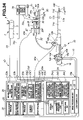
- FIG. 7 is a cross-sectional view in the lateral direction illustrating the internal configuration of the electrically-driven advance/retreat device
- FIG. 8 is a plan view of an electrically-driven operation device in which the handle of a treatment tool is installed as viewed from above;
- FIG. 9 is a side view of the electrically-driven operation device in which the handle of a treatment tool is installed as viewed from side;
- FIG. 10 is a flowchart describing a procedure for determining whether operation of a treatment tool is manually performed using a CPU, or is performed by programmed control;
- FIG. 11 is a diagram describing a state when determination is made regarding whether to operate a biopsy forceps manually or by programmed control;
- FIG. 12 is a diagram describing a state in which a biopsy forceps is operated by leaning the operating lever of the operation instructing device in an intermediate region between advancement and closing operation;
- FIG. 13 is a diagram describing a state in which a biopsy forceps is operated in a programmed-control state by the biopsy-forceps program illustrated in FIG. 14 ;
- FIG. 14 is a diagram describing one control example by the biopsy-forceps program
- FIG. 15 is a diagram describing another control example of the biopsy-forceps program.
- FIG. 16 is a diagram describing operation of a tissue sampling unit at the time of programmed control of a biopsy forceps in the event that a second sensor is a tissue pressure-force detection sensor;
- FIG. 17 is a diagram describing the overall configuration of an endoscope system in which a treatment tool is a high-frequency snare;
- FIG. 18A is a diagram describing a state when determination is made regarding whether to operate a high-frequency snare manually or by programmed control;
- FIG. 18B is a diagram describing a state in which a high-frequency snare is operated in a programmed-control state
- FIG. 18C is a diagram describing a state in which operation of a high-frequency snare is completed in a programmed-control state
- FIG. 19 is a diagram describing a control example using a high-frequency snare program
- FIG. 20 is a diagram describing the overall configuration of an endoscope system wherein a treatment tool is a basket forceps;
- FIG. 21A is a diagram describing a state when determination is made regarding whether to operate a basket forceps manually or by programmed control;
- FIG. 21B is a diagram describing a state in which a calculus is taken in a stone extracting basket in a programmed-control state by the basket-forceps program illustrated in FIG. 22 ;
- FIG. 22 is a diagram describing one control example using a basket-forceps program
- FIG. 23A is a diagram describing a state when determination is made regarding whether to operate a basket forceps manually or by programmed control;
- FIG. 23B is a diagram describing a state in which a calculus is taken in a stone extracting basket in a programmed-control state by the basket-forceps program illustrated in FIG. 24 ;
- FIG. 24 is a diagram describing another control example by a basket-forceps program
- FIG. 25 is a diagram describing the overall configuration of an endoscope treatment system including a puncture needle and an injector as treatment tools for injecting the liquid of the injector into tissue;
- FIG. 26A is a diagram describing a state when determination is made regarding whether to inject liquid manually or by programmed control
- FIG. 26B is a diagram describing a state in which a needle tube punctures tissue in a programmed-control state
- FIG. 26C is a diagram describing a state in which the liquid of an injector is injected through the needle tube in a programmed-control state
- FIG. 27 is a diagram describing one control example using an injector program
- FIG. 28 is a diagram describing another control example using an injector program
- FIG. 29 is a diagram describing the overall configuration of an endoscope system in which a treatment tool is a spray tube;
- FIG. 30 is a diagram describing a control example using a spray program
- FIG. 31A is diagram describing a state in which the pigment is sprayed in a programmed-control state
- FIG. 31B is a diagram describing a state in which the pigment is sprayed over the entire inner wall in a programmed-control state
- FIG. 32 is a diagram describing the overall configuration of an endoscope system wherein a treatment tool is a marking device
- FIG. 33A is a diagram describing a state when determination is made regarding whether to perform marking manually or by programmed control
- FIG. 33B is a diagram describing a state in which the needle scalpel is pressed against tissue in a programmed-control state
- FIG. 33C is a diagram describing a marking portion formed in a programmed-control state
- FIG. 34 is an overall diagram describing another configuration of an endoscope system wherein a treatment tool is a marking device.
- FIG. 35 is a diagram describing a control example using a marking program.
- FIG. 1 through FIG. 16 One embodiment of the present invention will be described with reference to FIG. 1 through FIG. 16 .
- an endoscope system 1 principally comprises an operation instructing device 2 , an endoscope 10 , a control device 20 , a treatment-tool operation-unit electrically-driven operation device (hereinafter, referred to as electrically-driven operation device) 30 , and a treatment-tool insertion-unit electrically-driven advance/retreat device (hereinafter, referred to as electrically-driven advance/retreat device) 40 .
- the operation instructing device 2 , control device 20 , electrically-driven operation device 30 , and electrically-driven advance/retreat device 40 make up an endoscope operation assisting device.
- the endoscope 10 comprises an insertion unit 11 , an operation unit 12 , and a universal cord 13 .
- the operation unit 12 also serves as a gripper, and is disposed at the base side of the insertion unit 11 .
- the universal cord 13 is extended to the side portion of the operation unit 12 , and a connector 13 a at base thereof is connected to the control device 20 .
- the insertion unit 11 is configured by a hard tip portion 11 a , a bendable bending portion 11 b , and a flexible tube portion 11 having flexibility being serially provided in order from the tip side.
- the operation unit 12 is provided with a folding-prevention portion 12 a connected to the base of the flexible tube portion 11 c .
- the operation unit 12 is provided with an air feed/water feed button 14 a for feeding air and water, a suction button 14 b for performing suction, bending knobs 15 a and 15 b for bending and operating the bending portion 11 b , and various types of switch 16 for performing control as to an endoscope image displayed on the screen of a display device, which is captured by image capturing means such as a CCD or the like provided at the tip portion 11 a , and so forth.
- image capturing means such as a CCD or the like provided at the tip portion 11 a
- the endoscope 10 includes a treatment-tool channel 11 e communicating between a treatment-tool opening 12 b and the tip opening 11 d of the tip portion 11 a .
- the treatment-tool channel 11 e is an introducing path for introducing a treatment tool into a body cavity.
- Various types of treatment tool such as a later-described biopsy forceps, high-frequency snare, basket forceps, and so forth are introduced into a body cavity via this treatment-tool channel 11 e.
- control device 20 inside thereof principally comprises a CPU 21 serving as a control unit, a storage device 22 such as a hard disk or the like serving as a storage unit, a signal input unit 23 , a control-signal output unit 24 , and so forth.
- the operating programs for operating a treatment tool are programs for operating a treatment tool introduced into a body cavity via the treatment-tool channel 11 e of the endoscope 10 as with an experienced surgeon operating that.
- the storage device 22 is registered with, for example, a biopsy-forceps program, high-frequency snare program, basket-forceps program, injector program, spray program, marking program, and so on as operating programs.
- the CPU 21 comprises, for example, a storage unit 21 a , a computing processing unit 21 b , a determining unit 21 c , and so forth.
- the signal input unit 23 principally comprises a manually-driven signal determining processing unit (hereinafter, referred to as manually-driven signal processing unit) 23 a , a programmed-control instruction-signal obtaining unit (hereinafter, abbreviated as instruction-signal obtaining unit) 23 b , a treatment-tool information obtaining unit 23 c , a sensor obtaining unit 23 d , and a motor rotating-speed obtaining unit 23 e.
- the sensor obtaining unit 23 d comprises multiple sensor obtaining units, for example, a first sensor obtaining unit 23 f , and a second sensor obtaining unit 23 g .
- the motor rotating-speed obtaining unit 23 e comprises multiple motor obtaining units, for example, a first motor obtaining unit 23 h , a second motor obtaining unit 23 j , and a third motor obtaining unit 23 k.
- the control-signal output unit 24 comprises, for example, an electrically-driven operation device control-signal output unit (hereinafter, referred to as first output unit) 24 a for outputting a control signal to the electrically-driven operation device 30 , and an electrically-driven advance/retreat-device control-signal output unit (hereinafter, referred to as second output unit) 24 b for outputting a control signal to the electrically-driven advance/retreat device 40 .
- first output unit an electrically-driven operation device control-signal output unit
- second output unit electrically-driven advance/retreat-device control-signal output unit
- reference numeral 25 denotes a light source unit, which controls an illumination state of illumination light which illuminates the inside of a body cavity.
- Reference numeral 26 denotes an image processing unit, which performs control of an image capturing device included in the endoscope 10 , processing for generating a video signal from an electric signal to be transmitted from the image capturing device, and so forth.
- the control device 20 is electrically connected with a display device, or the control device 20 includes a display device such as liquid-crystal monitor (not shown) for displaying an endoscope image in response to receiving a video signal processed at the image processing unit 26 .
- the control device 20 is electrically connected with the operation instructing device 2 , electrically-driven operation device 30 , and electrically-driven advance/retreat device 40 via signal cables 2 a , 30 a , and 40 a .
- the electrically-driven operation device 30 is installed with a handle portion 53 serving as a treatment tool, for example, serving as the operation unit of a biopsy forceps 50 .
- the electrically-driven operation device 30 performs an opening/closing operation of a tissue sampling unit 51 serving as the function unit of the biopsy forceps 50 by moving the handle portion 53 .
- the electrically-driven advance/retreat device 40 is installed in a treatment-tool attachment 12 c including the treatment-tool opening 12 b of the endoscope 10 .
- the electrically-driven advance/retreat device 40 performs advance/retreat movement of a sheath 52 serving as the treatment-tool insertion unit of the biopsy forceps 50 .
- the handle operation of the electrically-driven operation device 30 , and the advance/retreat movement of the electrically-driven advance/retreat device 40 are performed in either of a manually-operated state by the operation instructing device 2 , or a programmed-control state based on the biopsy-forceps program registered on the storage device 22 .
- the biopsy forceps 50 comprises a tissue sampling unit 51 , a slender sheath 52 , and a handle portion 53 in order from the tip side.
- the tissue sampling unit 51 is provided at the tip of the sheath 52 .
- the tissue sampling unit 51 includes a pair of biopsy cups 51 a and 51 b , and the biopsy cups 51 a and 51 b are configured so as to be openable and closable.
- the biopsy cups 51 a and 51 b are each provided with a first sensor 51 c which is a tissue contact pressure detection sensor serving as first detection means, and a second sensor 51 d which is a closed-state detection sensor serving as second detection means.
- the first sensor 51 c is provided at the tip side of at least one of the cups 51 a and 51 b .
- the one second sensor 51 d or a pair of the second sensors 51 d are provided so as to detect being in contact in the position facing the cups 51 a and 51 b , i.e., so as to detect a closed state.
- the maximum outer shape of the tissue sampling unit 51 is configured so as to be a size which can be inserted into the treatment-tool channel 11 e , or so as to be smaller than the outside diameter dimension of the insertion unit 11 in a closed state of the cups 51 a and 51 b.
- the tissue contact pressure detection sensor detects, by the tip side faces of the biopsy cups 51 a and 51 b coming into contact with a body tissue, contact pressure thereof, and outputs a pressure detection signal (hereinafter, referred to as pressure signal) serving as the electric signal corresponding change in pressure thereof.
- the closed-state detection sensor outputs a closed-state detection signal (hereinafter, referred to as closed signal) to the control device 20 at the time of a closed state in which the biopsy cups 51 a and 51 b are in contact with each other.
- Signal lines which are not shown are extended from the respective sensors 51 c and 51 d .
- the other end portions of the signal lines are connected to the electric contact point (see reference numeral 57 in FIG. 9 ) provided at a slider 55 passing through the sheath 52 .
- An operating wire (not shown) other than the above signal lines is inserted into the sheath 52 of the biopsy forceps 50 .
- the operating wire advances or retreats depending on operation of the handle portion 53 . That is to say, the tissue sampling unit 51 changes from an open state to a closed state, or to a reversed state thereof, by operating the handle portion 53 to advance or retreat the operating wire.
- the handle portion 53 comprises a finger-hooking ring 54 and a slider 55 .
- the finger-hooking ring 54 includes a hole portion where the thumb of a user is disposed for example.
- the slider 55 includes a pair of flanges where the second finger and third finger of the user are disposed on the way thereof.
- the finger-hooking ring 54 has built in, for example, a non-contact IC chip (hereinafter, referred to as IC chip) 56 making up the treatment-tool information unit side of the RFID serving as treatment-tool identifying means. Treatment-tool information indicating the type of treatment tool thereof is registered on the IC chip 56 .
- IC chip non-contact IC chip
- the operation instructing device 2 comprises, for example, a general cylindrical hard main body portion 3 , and a grip body 4 to be serially connected to the main body portion 3 .
- the grip body 4 is made up of, for example, an elastic member, and the above signal cable 2 a is extended from the base of the grip body 4 .
- a fitting protruding portion 3 a is protruded from the center of the base face of the main body portion 3 .
- the main body portion 3 and the grip body 4 are formed in an integrated manner by the fitting protruding portion 3 a being fitted into a fitting hole opened in the tip face of the grip body 4 .
- a grip portion 4 a configured in an uneven shape is provided on the grip body 4 .
- the grip portion 4 a is provided on the side face which assumes the positional relation of the opposite side of the manually-driven operation unit 5 of the main body portion 3 . A surgeon grips the grip portion 4 a , whereby slippage is prevented, and the surgeon can grip the operation instructing device 2 in a sure manner.
- the side circumferential face of the main body portion 3 is provided with a manually-driven operation instructing unit (hereinafter, referred to as manually-driven operation unit) 5 serving as a first operation instructing unit, and a programmed-control instructing unit (hereinafter, referred to as programmed instruction unit) 6 serving as a second operation instructing unit.
- manually-driven operation unit hereinafter, referred to as manually-driven operation unit
- programmed instruction unit serving as a second operation instructing unit.
- the tip face side of the main body portion 3 is referred to as the tip side
- the base face side of the grip body 4 as the base side
- the manually-driven operation unit 5 side provided in the main body portion 3 as the upper portion
- the grip portion 4 a side provided on the grip body 4 as the lower portion.
- multiple signal lines are inserted into the signal cable 2 a.
- the manually-driven operation unit 5 is a so-called joystick-type operating lever 5 a which is leaned and operated, which is a return-to-origin-type switch which can be operated with two axes.
- the operating lever 5 a is configured so as to be supported by an operating lever supporting portion 5 b .
- the manually-driven operation unit 5 outputs an operation instructing signal serving as a first instruction signal to the manually-driven signal processing unit 23 a of the signal input unit 23 .
- a treatment tool is the biopsy forceps 50 including the tissue sampling unit 51 which can be opened and closed at the tip side of the slender sheath 52
- the operation instructing signal corresponding to lever operation thereof is output to the control device 20 from the manually-driven operation unit 5 .
- an advance signal serving as a signal for instructing operation for advancing the sheath 52 is output.
- a retreat signal serving as a signal for instructing operation for retreating the sheath 52 is output.
- an opening signal for instructing operation of opening the tissue sampling unit 51 is output.
- a closing signal for instructing operation for closing the tissue sampling unit 51 is output.
- An arrangement may be made wherein the top face of the operating lever supporting portion 5 b of the manually-driven operation unit 5 is provided with a reference mark indicating the operating instruction of the biopsy forceps 50 corresponding to the leaned direction of the operating lever 5 a .
- Examples of the reference mark include letters such as illustrated in FIG. 4 .
- Reference mark “F” indicating advancement toward the tip side of the operating lever supporting portion 5 b
- reference mark “B” indicating retreat toward the base side
- reference mark “0” indicating opening operation to the left side as viewed from the upper direction toward the tip
- reference mark “C” indicating closing operation to the right side as viewed from the upper direction toward the tip are printed.
- an advance signal or retreat signal, and an opening signal or closing signal are configured so as to be output simultaneously.
- advance/retreat speed and opening/closing speed are arranged so as to be changed depending on difference of a leaning angle when leaning and operating the operating lever 5 a . For example, as the leaning angle of the operating lever 5 a is greatly leaned as to the initial position, advance/retreat speed and opening/closing speed are set so as to gradually reach high speed.
- the programmed instruction unit 6 is provided, for example, at the left side (lower side in the drawing) as viewed from the upper direction toward the tip, and at the side face shifted 90 degrees as to the circumferential direction.
- the programmed instruction unit 6 is, for example, a push-to-connect type, which is a type switch to be held at the position illustrated in the solid line following being pressed. This switch is in an OFF state at the time of a protruding state illustrated in the dashed line.
- a pushed state illustrated in the solid line is an ON state, and in other words, a programmed-control instruction signal serving as the second instruction signal is output to the instruction-signal obtaining unit 23 b of the signal input unit 23 .
- the user when returning the above programmed instruction unit 6 to an ON state or OFF state, the user further subjects the programmed instruction unit 6 to a pushing-in operation once more.
- the programmed instruction unit 6 may be a press-to-contact-type switch for returning to the original state following being pushed in.
- a so-called wired type is employed by connecting between the operation instructing device 2 and the control device 20 via the signal cable 2 a .
- the relation between the operation instructing device 2 and the control device 20 is not restricted to a wired type, or rather may be a wireless type such as the operation instructing device 2 A illustrated in FIG. 5 .
- the operation instructing device 2 A comprises, for example, a transmitter 7 within the main body portion 3 , and electric supply battery 8 within the grip body 4 .
- the operation instructing device 2 A transmits an operation instructing signal accompanying operation of the operating lever 5 a , or a programmed-control instructing signal to be output from the programmed instruction unit 6 to the control device 20 via the transmitter 7 using electric power from the battery 8 .
- the control device 20 is arranged so as to include a receiver (not shown) for receiving a signal to be transmitted from the transmitter 7 .
- the electrically-driven advance/retreat device 40 comprises two rollers 43 a and 43 b , which can move rotationally, within a box body 41 .
- the box body 41 comprises a treatment-tool insertion unit 42 wherein the sheath 52 of the biopsy forceps 50 is inserted into one face side of facing faces thereof.
- the treatment-tool insertion unit 42 is provided with a communicating hole 42 a .
- a forceps plug 42 b made up of an elastic member is provided at the communicating hole 42 a .
- a slit 42 c into which the sheath 52 is inserted is provided at the forceps plug 42 b .
- the other face side of the box body 41 is provided with a sheath inserting hole 41 a through which the sheath 52 inserted via the slit 42 c passes.
- the circumference of the sheath inserting hole 41 a is provided with a scope fixing unit 41 b for connecting and fixing the box body 41 to the treatment-tool attachment 12 c .
- the scope fixing unit 41 b is connected to the treatment-tool attachment 12 c in an airtight manner.
- the two rollers 43 a and 43 b provided within the box body 41 are each made up of a resin member having elasticity.
- the rollers 43 a and 43 b are fixed to the corresponding rotational movement shafts 43 A and 43 B in an integrated manner.
- the outer face of the sheath 52 inserted via the slit 42 c is pressed and nipped by the respective rollers 43 a and 43 b .
- the rotational movement shaft 43 A is a driving shaft, and is moved rotationally by a motor 44 disposed within the box body 41 .
- the rotational movement shaft 43 B is a driven shaft, and is disposed within the box body 41 so as to be moved rotationally.
- the motor 44 is provided with an encoder 44 a for detecting the amount of rotation and rotational angle of the motor.
- the detection value of the encoder 44 a is output to the second motor obtaining unit 23 j of the motor rotating-speed obtaining unit 23 e via the signal cable 40 a.
- the motor 44 is driven by a control signal being output from the second output unit 24 b to the electrically-driven advance/retreat device 40 via the signal cable 40 a . Subsequently, the motor 44 is driven in a state in which the sheath 52 is nipped between the rollers 43 a and 43 b , whereby the rotational movement shaft 43 A is rotated. Then, the sheath 52 nipped between the rollers 43 a and 43 b advances or retreats along with rotational movement of the roller 43 a .
- the CPU 21 controls driving of the motor 44 to advance or retreat the sheath 52 disposed within the treatment-tool channel 11 e a predetermined distance.
- the motor 44 is driven and controlled by the CPU 21 based on an advance signal, retreat signal to be output along with leaning operation of the operating lever 5 a , or the operating program registered on the storage device 22 .
- rotational movement shafts 43 A and 43 B are supported so as to be moved rotationally by the side wall of the box body 41 and a support plate member 41 c such that the rotational movement shafts 43 A and 43 B come in parallel with each other, and also the roller faces of the respective rollers 43 a and 43 b securely installed to the rotational movement shafts 43 A and 43 B are separated at a predetermined interval.
- the electrically-driven operation device 30 includes a plate-shaped base member 31 .
- the base member 31 is securely installed with a ring-retainer portion 32 , a holding box 37 , and an installation portion 38 .
- the holding box 37 is securely installed to the base member 31 via a pair of fixing members 37 a and 37 b .
- a rack 35 making up a linear cog 35 a is held linearly in the holding box 37 so as to be advanced or retreated.
- a pinion gear 36 a for gearing with the linear cog 35 a of the rack 35 is disposed within the holding box 37 .
- the pinion gear 36 a is securely installed to the motor shaft 36 b of the motor 36 .
- the pinion gear 36 a meshes with the linear cog 35 a provided to the rack 35 , the pinion gear 36 a securely installed to the motor shaft 36 b is moved rotationally, and the rack 35 advances or retreats along with rotational movement thereof.
- the motor 36 is provided with an encoder 36 c for detecting the amount of rotation, and rotational angle of the motor.
- the detection value of the encoder 36 c is output to the first motor obtaining unit 23 h of the motor rotating-speed obtaining unit 23 e via the signal cable 30 a.
- the motor 36 is driven by a control signal being output from the first output unit 24 a to the electrically-driven operation device 30 via the signal cable 30 a .
- the rack 35 is moved along with driving of the motor 36 .
- a slider 55 held by a slider-retainer portion 33 advances or retreats along the shaft of the handle portion 53 a predetermined distance.
- the CPU 21 controls driving of the motor 36 to move the rack 35 , and thus, moves the slider 55 fixed with the base portion of the operating wire to subject the tissue sampling unit 51 making up the biopsy forceps 50 to opening/closing operation.
- the motor 36 is driven and controlled by the CPU 21 based on an opening signal or closing signal to be output along with leaning operation of the operating lever 5 a , or the operating program registered on the storage device 22 .
- one end portion of the rack 35 is arranged so as to be attached with the slider-retainer portion 33 including a holder 33 a via a setscrew 34 .
- the holder 33 a making up the slider-retainer portion 33 is disposed sandwiching the slider 55 making up the handle portion 53 .
- the holder 33 a holds the slider 55 so as to sandwich the body between a pair of flanges provided at the slider 55 .
- the ring-retainer portion 32 comprises a ring pedestal 32 a and a protrusion 32 b .
- the ring pedestal 32 a is securely installed to the base body 31 .
- the protrusion 32 b is inserted and disposed into the finger-hooking ring 54 making up the handle portion 53 .
- the protrusion 32 b is provided with a treatment-tool information reader device (hereinafter, referred to as reader/writer) 32 c which is an information reading unit for reading the treatment tool information registered on the IC chip 56 .
- reader/writer 32 c and the IC chip 56 together make up an RFID.
- the hole portion of the finger-hooking ring 54 is disposed on the protrusion 32 b , whereby the handle portion 53 is integrally fixed and held by the electrically-driven operation device 30 .
- the information of the IC chip 56 is read by the reader/writer 32 c , and treatment-tool information thereof is output to the treatment-tool information obtaining unit 23 c of the control device 20 via the signal cable 30 a .
- the CPU 21 determines the presence or type of a treatment tool from the treatment-tool information output to the treatment-tool information obtaining unit 23 c.
- the finger-hooking ring 54 Upon the finger-hooking ring 54 being disposed on the protrusion 32 b in a predetermined state, one face of the finger-hooking ring 54 comes into contact with the ring pedestal 32 a . In this disposed state, a part of the handle portion 53 is disposed on the installation portion 38 . Thus, the handle portion 53 of the biopsy forceps 50 is disposed in parallel in a state separated from the base body 31 .
- the installation portion 38 is provided with an electric connection portion 38 a to be electrically connected to the electric contact portion 57 . Accordingly, the handle portion 53 is installed in the installation portion 38 , thereby leading to a state in which the electric contact portion 57 and the electric connection portion 38 a are electrically connected.
- the pressure signal to be output from the first sensor 51 c , and the closed-state signal to be output from the second sensor 51 d are output to the control device 20 via a signal line (not shown), the electric contact portion 57 , electric connection portion 38 a , and signal cable 30 a . Subsequently, the pressure signal is input to, for example, the first sensor obtaining unit 23 f provided in the sensor obtaining unit 23 d , and the closed-state signal is input to the second sensor obtaining unit 23 g.
- the outside diameter dimension of the protrusion 32 b making up the ring-retainer portion 32 is formed generally equal to the inside diameter of the hole portion of the finger-hooking ring 54 . Accordingly, the handle portion 53 is securely held by the ring-retainer portion 32 .
- the outside diameter dimension of the protrusion 32 b of the ring-retainer portion 32 may be set to be slightly smaller than the inside diameter of the hole portion of the finger-hooking ring 54 .
- the outer circumference of the protrusion 32 b is covered with a tube body having elasticity.
- the endoscope system 1 upon a surgeon leaning and operating the operating lever 5 a provided in the operation instructing device 2 , the first instruction signal corresponding to the leaned direction is output to the manually-driven signal processing unit 23 a of the signal input unit 23 via the signal cable 2 a.
- a sheath advance operation instructing signal for operating the sheath 52 , or a retreat signal is output to the manually-driven signal processing unit 23 a from the manually-driven operation unit 5 .
- the advance signal or the retreat signal input to the manually-driven signal processing unit 23 a is output to the electrically-driven advance/retreat device 40 via the second output unit 24 b of the control-signal output unit 24 , and the signal cable 40 a as a control signal under control of the CPU 21 .
- the driving side roller 43 a is moved rotationally for a predetermined amount depending on the leaning operation of the operating lever 5 a , and the sheath 52 which is pressed and nipped between the rollers 43 a and 43 b is advanced or retreated along with rotational movement thereof.
- the tissue sampling unit 51 advances or retreats.
- an opening signal or closing signal is output to the manually-driven signal processing unit 23 a .
- the opening signal or closing signal input to the manually-driven signal processing unit 23 a is output to the electrically-driven operation device 30 via the first output unit 24 a of the output unit 24 , and the signal cable 30 a as a control signal under control of the CPU 21 .
- the pinion gear 36 a provided in the motor shaft 36 b is moved rotationally for a predetermined amount depending on the leaning operation of the operating lever 5 a .
- the rack 35 including the linear cog 35 a which meshes with the pinion gear 36 a advances or retreats along with rotational movement of the pinion gear 36 a .
- the slider 55 is advanced or retreated along the shaft of the handle portion 53 by the slider 55 being held by the slider-retainer portion 33 connected to the rack 35 .
- the operating wire is advanced or retreated, and the tissue sampling unit 51 is subjected to an opening operation or closing operation.
- the surgeon can perform an operation for guiding the tissue sampling unit 51 out from the tip portion 11 a side of the insertion unit 11 toward the tissue direction, and an operation for pulling back the tissue sampling unit 51 from the tissue direction side to the tip portion 11 a side by leaning and operating the operating lever 5 a in the tip direction or base direction. Also, the surgeon can perform an operation for making the tissue sampling unit 51 an open state, and an operation for making it a closed state by leaning the operating lever 5 a in the above left direction or the above right direction.
- a treatment-tool operation in the above endoscope system 1 is arranged so as to be selectively switched to a manually-driven operating state in which a treatment tool is operated in accordance with the surgeon's side operation of the operating lever 5 a , or a programmed-control state in which a treatment tool is operated in accordance with the operating program registered beforehand.
- the control device 20 of the endoscope system 1 is set to an ON state.
- the CPU 21 performs processing for obtaining treatment-tool information using the treatment-tool information obtaining unit 23 c as shown in step S 1 in FIG. 10 . That is to say, the CPU 21 confirms the presence of the treatment-tool information by accessing the treatment-tool information obtaining unit 23 c .
- the CPU 21 proceeds to step S 3 , and performs processing for performing error display.
- the CPU 21 proceeds to step S 4 , and stores the treatment-tool information in the storage unit 21 a .
- the control device 20 enters a state in which the type of a treatment tool has been identified.
- the CPU 21 monitors whether or not the instruction signal to be output from the operation instructing device 2 is input to the signal input unit 23 as shown in step S 5 .
- the CPU 21 determines in step S 6 that the instruction signal is the first instruction signal
- the CPU 21 enters a manually-driven operating state.
- the CPU 21 determines whether the first instruction signal is the instruction signal corresponding to the electrically-driven operation device 30 or the instruction signal corresponding to the electrically-driven advance/retreat device 40 .
- the CPU 21 outputs the control signal corresponding to the instruction signal to the electrically-driven operation device 30 from the output unit 24 a , and/or outputs this to the electrically-driven advance/retreat device 40 from the output unit 24 b .
- the tissue sampling unit 51 performs at least one of an advance/retreat operation or an opening/closing operation along with the surgeon's operation of the operating lever 5 a.
- step S 6 determines in step S 6 that the instruction signal is the second instruction signal
- the CPU 21 proceeds to step S 7 , and selects and executes the operating program to enter a programmed-control state. That is to say, in step S 7 the CPU 21 accesses the storage device 22 to select the operating program corresponding to the treatment-tool information stored in the storage unit 21 a of the programs registered on the storage device 22 , and executes the selected program to operate a treatment tool.
- a biopsy-forceps operating program for operating the biopsy forceps 50 is executed.
- the CPU 21 outputs the control signal in accordance with the program to the electrically-driven operation device 30 or/and the electrically-driven advance/retreat device 40 from the output units 24 a and 24 b .
- the tissue sampling unit 51 performs an advance/retreat operation and an opening/closing operation based on the program.
- the staff inserts the finger-hooking ring 54 until one face of the finger-hooking ring 54 in contact on the ring pedestal 32 a of the ring-retainer portion 32 , and also makes the transition to a state in which a part of the handle portion 53 is mounted on the installation portion 38 . Subsequently, as illustrated in FIG. 9 , the staff connects the slider-retainer portion 33 and the rack 35 using the setscrew 34 .
- the staff mounts the electrically-driven advance/retreat device 40 on the treatment-tool attachment 12 c of the endoscope 10 (see FIG. 6 ). Subsequently, the staff inserts the sheath 52 of the biopsy forceps 50 into the treatment-tool channel 11 e of the endoscope 10 via the electrically-driven advance/retreat device 40 and the treatment-tool opening 12 b . Thus, the sheath 52 of the biopsy forceps 50 is in a state of being pressed and nipped between the two rollers 43 a and 43 b.
- the staff connects the signal cable 2 a extended from the operation instructing device 2 to the control device 20 , and also connects the universal cord 13 and the signal cables 30 a and 40 a to the control device 20 .
- the medical staff first turns the power of the control device 20 to an ON state. Then, the treatment-tool information registered on the IC chip 56 provided in the handle portion 53 is read by the reader/writer 32 c provided in the protrusion 32 b , and is output to the treatment-tool information obtaining unit 23 c . Then, the CPU 21 stores the treatment-tool information that the treatment tool is the biopsy forceps 50 in the storage unit 21 a , and monitors input of an instruction signal.
- the surgeon inserts the insertion unit 11 of the endoscope 10 toward a target portion within the body cavity of a subject while observing an endoscope image. Subsequently, the surgeon performs an insertion operation, and a bending operation for bending the bending portion 11 b , and so forth while observing an endoscope image on the screen, and confronts the tip portion 11 a of the insertion unit 11 with the tissue of the target portion so as to facilitate treatment.
- the surgeon moves and operates the tissue sampling unit 51 disposed in the vicinity of the treatment-tool opening 12 b by leaning and operating the operating lever 5 a so as to protrude the tissue sampling unit 51 from the tip face of the tip portion 11 a of the endoscope, and also performs an operation for confronting the tissue sampling unit 51 of the biopsy forceps 50 with the vicinity of tissue 60 as illustrated in FIG. 11 .
- the surgeon selects whether to perform sampling of tissues by manually operating the biopsy forceps 50 while observing an endoscope image, or perform sampling of tissues by operating the biopsy forceps 50 under programmed control.
- the surgeon leans the operating lever 5 a of the operation instructing device 2 , for example, to an area between the reference mark “F” and reference mark “C”, as illustrated in FIG. 12 .
- the tissue sampling unit 51 performs an operation for advancing toward the tissue 60 as illustrated in the arrow a, and also performs an operation for closing as illustrated in the arrow b.
- the tissue sampling unit 51 can perform sampling of the tissue 60 by changing the tissue sampling unit 51 from an open state to a closed state while moving toward the tissue by the surgeon leaning and operating the operating lever 5 a to an area between the reference mark “F” and reference mark “C”, as illustrated in the drawing.
- the pressure value calculated from the pressure signal to be output from the first sensor 51 c is arranged so as to be displayed on an unshown display panel included in the control device 20 .
- a closed-state detection signal is output from the second sensor 51 d , for example, a sampling-state notification lamp (not shown) included in the control device 20 is arranged to change from a blinking state to a lit state so as to notify that the tissue sampling unit 51 is in a closed state.
- the surgeon confronts the tissue sampling unit 51 of the biopsy forceps 50 with the vicinity of the tissue 60 as illustrated in FIG. 11 , following which sets the tissue sampling unit 51 to a desired open state, and pushes in and operates the programmed instruction unit 6 such as illustrated in FIG. 13 .
- the second instruction signal is output from the manually-driven operation unit 5 to the instruction-signal obtaining unit 23 b .
- the tissue sampling unit 51 enters a programmed-control state of being operated based on the biopsy-forceps program registered on the storage device 22 .
- the CPU 21 performs control for advancing the tissue sampling unit 51 while keeping the open state of the tissue sampling unit 51 , as shown in step S 12 . That is to say, the CPU 21 outputs a control signal for keeping the open state of the tissue sampling unit 51 to the electrically-driven operation device 30 from the first output unit 24 a . Also, the CPU 21 outputs a control signal for advancing the tissue sampling unit 51 in the arrow a direction toward the tissue 60 at a predetermined speed to the electrically-driven advance/retreat device 40 from the second output unit 24 b . Then, the tissue sampling unit 51 advances toward the tissue along with rotation of the motor 44 , and a detection value to be output from the encoder 44 a is consecutively input to the second motor obtaining unit 23 j in accordance with advancement thereof.
- step S 13 when determining in step S 13 that the pressing pressure value has reached the sampling start pressure P, the CPU 21 performs the processing in step S 14 .
- step S 14 the CPU 21 extracts the detection value of the encoder 44 a , which indicates the amount of rotation of the motor 44 at the time of the tissue sampling unit 51 being in contact with the tissue 60 , from the second motor obtaining unit 23 j to register this on the storage unit 21 a .
- the CPU 21 obtains the difference between the detection value of the encoder 44 a registered on the storage unit 21 a and the detection value of the encoder 44 a registered this time to calculate the movement distance from the origin of the tissue sampling unit 51 to the tissue, and registers this as the amount of return.
- step S 15 the CPU 21 performs control for causing the tissue sampling unit 51 to perform a closing operation. Specifically, the CPU 21 performs control for stopping advancement of the tissue sampling unit 51 , and control for causing the biopsy cups 51 a and 51 b to perform a closing operation in the arrow b direction at the most appropriate speed for sampling of tissue.
- the CPU 21 outputs a control signal for stopping advancement of the tissue sampling unit 51 to the electrically-driven advance/retreat device 40 from the second output unit 24 b . Also, the CPU 21 outputs a control signal for closing the biopsy cups 51 a and 51 b at the most appropriate predetermined speed for sampling of tissue to the electrically-driven operation device 30 from the first output unit 24 a.
- the CPU 21 determines in step S 16 whether or not the tissue sampling unit 51 in an open state illustrated in the solid line in FIG. 13 has changed to a closed state as illustrated by the dashed line. That is to say, the CPU 21 monitors whether or not the closed-state signal to be output from the second sensor 51 d is input to the second sensor obtaining unit 23 f.
- step S 17 the CPU 21 performs control for keeping the tissue sampling unit 51 in a closed state, and control for retreating the tissue sampling unit 51 in the arrow c direction at a predetermined speed. That is to say, the CPU 21 outputs a control signal for keeping the tissue sampling unit 51 in a closed state to the electrically-driven operation device 30 from the first output unit 24 a . Also, the CPU 21 retreats the tissue sampling unit 51 in the arrow c direction only for the above amount of return at a predetermined speed to the electrically-driven advance/retreat device 40 from the second output unit 24 b , following which outputs a control signal for further retreating the tissue sampling unit 51 only the removal distance from the origin.
- the tissue sampling unit 51 which has performed sampling of tissue, and is kept in a closed state, starts movement toward the arrow c direction, retreats to the vicinity of the treatment-tool opening 12 b via the treatment-tool channel 11 e from the tip opening 11 d , and stops. That is to say, a programmed-control state by the biopsy-forceps program ends.
- the surgeon turns off the programmed instruction unit 6 to cancel a programmed-control state.
- the surgeon or staff extracts the tissue sampling unit 51 from the treatment-tool opening 12 b to collect the tissue sampled at the tissue sampling unit 51 .
- the endoscope system principally comprises the operation instructing device, endoscope, control device, electrically-driven operation device, and electrically-driven advance/retreat device.
- a treatment-tool operating program for causing a treatment tool to be mounted on the electrically-driven advance/retreat device to perform the corresponding treatment operation is registered on the storage device of the control device, and also the manually-driven operation instructing unit and a programmed operation instructing unit are provided in the operation instructing device.
- a surgeon can selectively perform a manually-driven treatment operation and a programmed-driven treatment operation regarding operation of a treatment tool to be mounted on the electrically-driven advance/retreat device as appropriate.
- the surgeon operates the programmed operation instructing unit, and the tissue sampling unit of a treatment tool is controlled and operated by the biopsy-forceps program, whereby even a physician who is inexperienced in treatment can perform sampling of tissue by making the biopsy cups into a closed state while pressing biopsy cups against tissue with the appropriate amount of force, as with a physician who is experienced in treatment.
- the biopsy-forceps program determines whether or not the pressing pressure caused by the advancing tissue sampling unit coming into in contact with tissue has reached the sampling start pressure P to output a control signal for switching the biopsy cups from an open state to a closed state. Accordingly, sampling of tissue can be performed in a closed state of the biopsy cups, in a sure manner.
- the biopsy-forceps program confirms that the biopsy cups are in a closed state, following which retreats the tissue sampling unit. Accordingly, sampling of tissue by the biopsy cups can be performed in a sure manner.
- biopsy-forceps program is not restricted to that illustrated in FIG. 14 , but rather programmed control such as shown in FIG. 15 may be employed, for example. Control of sampling of tissue by the biopsy-forceps program will be described with reference to FIG. 15 .
- FIG. 15 the same steps as those in FIG. 14 are appended with the same step numbers to simplify description thereof.
- the CPU 21 In a programmed-control state, the CPU 21 first performs origin processing in step S 11 , as with the above programmed control. Subsequently, the CPU 21 performs control for advancing the tissue sampling unit 51 while keeping the open state of the tissue sampling unit 51 , as shown in step S 112 . Thus, the tissue control unit 51 advances toward the tissue along with rotation of the motor 44 , and the detection value to be output from the encoder 44 a is consecutively input to the second motor obtaining unit 23 j.
- step S 19 the CPU 21 performs control for advancing the tissue sampling unit 51 in the arrow a direction, and control for causing the biopsy cups 51 a and 51 b to perform a closing operation in the arrow b direction at the most appropriate speed for sampling of tissue.
- the CPU 21 detects a pressure signal, following which outputs a control signal for advancing the tissue sampling unit 51 at a predetermined speed only for a predetermined distance to the electrically-driven advance/retreat device 40 from the second output unit 24 b .
- the CPU 21 outputs a control signal for closing the biopsy cups 51 a and 51 b at the most appropriate predetermined speed for sampling tissue to the electrically-driven operation device 30 from the first output unit 24 a .
- the biopsy cups 51 a and 51 b are changed into a closed state.
- step S 116 determines in step S 116 whether or not the tissue sampling unit 51 in an open state illustrated with the solid line in FIG. 13 has been changed into a closed state illustrated with the dashed line. Then, upon the cups making up the tissue sampling unit 51 , which is subjected to a closing operation, coming into contact with each other, the CPU 21 determines that the tissue sampling unit 51 has been changed into a closed state, and proceeds to step S 17 via step S 14 .
- an arrangement has been made wherein the tissue sampling unit 51 of the biopsy forceps 50 is confronted with the vicinity of the tissue 60 such as illustrated in FIG. 11 , following which a surgeon sets the tissue sampling unit 51 to a desired open state, and pushes in and operates the programmed instruction unit 6 .
- an arrangement may be made wherein in a state in which the tissue sampling unit 51 is set to a desired open state, a surgeon presses the tissue sampling unit 51 against the tissue 60 , following which the surgeon pushes in and operates the programmed instruction unit 6 to set to a programmed-control state.
- the CPU 21 performs control from step S 14 in FIG. 14 , or control from the step S 119 in FIG.
- the sensor detects that the tissue sampling unit has changed from an open state to a closed state.
- programmed control may be employed wherein a control signal for operating the tissue sampling unit from an open state to a closed state only for a predetermined amount is output from the electrically-driven operation device.
- the second sensor 51 d is a closed-state detection sensor for outputting a closed-state signal at the time of a state in which the biopsy cups 51 a and 51 b are closed.
- the second sensor 51 d is not restricted to a closed-state detection sensor, and a tissue compressed-force detection sensor (hereinafter, referred to as compressed sensor) may be employed for detecting compressed force applied to the tissue held between the biopsy cup 51 a and the biopsy cup 51 b , and outputting compressed force thereof as an electric signal.
- the biopsy cups 51 a and 51 b are closed and operated at the most appropriate speed for sampling of tissue. Then, as illustrated in FIG. 13 , the tissue is held between the biopsy cups 51 a and 51 b , following which an electric signal is output to the second sensor obtaining unit 23 g from the compressed sensor serving as the second sensor.
- the CPU 21 outputs an electric signal to be output from the second sensor 51 d and to be input consecutively to the second sensor obtaining unit 23 f to the computing processing unit 21 b , and performs computing processing to obtain compressed pressure instead of monitoring whether or not the closed-state signal to be output from the second sensor 51 d is input to the second sensor obtaining unit 23 f in step S 16 .
- the CPU 21 outputs compressed pressure value thereof to the determining unit 21 c to compare and determine at the determining unit 21 c whether or not the compressed pressure value has reached the most appropriate tissue sampling start pressure registered on the program at the time of performing sampling of tissue.
- the CPU 21 performs control for collecting tissue in the tissue sampling unit 51 . That is to say, in the state illustrated with the solid line in FIG. 16 , the CPU 21 outputs a control signal for retreating the tissue sampling unit 51 in the arrow c direction only for a predetermined distance at a predetermined speed to the electrically-driven operation device 30 from the first output unit 24 a .
- the tissue sampling unit 51 is moved in a state of holding the tissue, and a tissue piece 60 a is sampled by the biopsy cups 5 l a and 51 b such as illustrated in the dashed line.
- the CPU 21 proceeds to step S 17 , retreats the tissue sampling unit 51 in a closed state to the vicinity of the treatment-tool opening 12 b , and ends control by the biopsy-forceps operating program.
- the tissue sampling start pressure is a value to be set within the program, and also is a value which can be set and modified using an operating panel.
- the tissue sampling unit 51 is provided with the first sensor 51 c and the second sensor 51 d .
- an arrangement may be made wherein only the second sensor 51 d serving as a compressed sensor is provided in the biopsy cups 51 a and 51 b making up the tissue sampling unit 51 .
- the placement position of the compressed sensor is taken into consideration. That is to say, the compressed sensor is disposed so as to obtain contact pressure at the time of advancing, and compressed pressure at the time of a closing operation.
- the number of sensors to be provided in the tissue sampling unit 51 is one type, whereby reduction in cost and so forth can be realized.
- the CPU 21 performs the origin processing in the advance/retreat direction in step S 111 , and also obtains the amount of opening in an open state which is set by the surgeon. This amount of opening is obtained as follows under control of the CPU 21 .
- the CPU 21 outputs a control signal for changing the tissue sampling unit 51 in an open state which is set by the surgeon into a closed state.
- the CPU 21 obtains the amount of rotation of the motor 36 until an electric signal is output from the compressed sensor. That is to say, the CPU 21 performs subtraction between the detection value of the encoder 36 c output when changing an open state to a closed state and the above detection value to obtain the amount of opening, and registers this on the storage unit 21 a .
- the CPU 21 outputs a control signal for changing the tissue sampling unit 51 into an open state only for the amount of opening registered on the storage unit 21 a to the electrically-driven operation device 30 from the first output unit 24 a .
- the tissue sampling unit 51 returns to the surgeon's desired open state again.
- the CPU 21 determines whether or not the open state of the tissue sampling unit is the amount of closing appropriate for sampling of tissue by obtaining the above amount of opening. Thus, in the event of determining that the amount of closing is appropriate for sampling of tissue, the CPU 21 outputs a control signal for sampling tissue at the tissue sampling unit 51 . On the other hand, in the event of determining that the amount of closing is not appropriate for sampling of tissue, the CPU 21 outputs a control signal for informing the surgeon to that effect. Thus, a problem wherein no tissue is sampled in the tissue sampling unit 51 is prevented.
- advancing speed, retreating speed, cup opening speed, cup closing speed, tissue sampling pressure, and so forth at the time of causing the tissue sampling unit to perform an advance/retreat operation or an opening/closing operation by programmed control can be set or modified using an unshown operating panel provided in the control device.
- the surgeon can perform target treatment by operating the tissue sampling unit in a desired manner at the time of programmed control.
- treatment-tool information is registered on, for example, a non-contact IC chip
- the treatment-tool information registered on the IC chip is read out by the treatment-tool information reading device, and the treatment-tool information is output to the treatment-tool information obtaining unit.
- an arrangement may be made wherein treatment-tool information is input at, for example, the operating panel provided on the control device, and is output to the treatment-tool information obtaining unit.
- a treatment tool is a high-frequency snare 50 A, and includes a high-frequency power supply device 70 .
- the high-frequency power supply device 70 supplies a high-frequency current to the high-frequency snare 50 A.
- the handle portion 53 of the high-frequency snare 50 A is set to the electrically-driven operation device 30 , as described above.
- the information of the IC chip 56 provided in the handle portion 53 is read by the reader/writer 32 c , and is output to the treatment-tool information obtaining unit 23 c of the signal input unit 23 .
- the slider 55 making up the handle portion 53 is advanced or retreated along the axis of the handle portion 53 , as with the above embodiment.
- a snare portion 51 A serving as a function unit is guided out from the tip of the sheath 52 .
- the snare portion 51 A forms a loop shape.
- the loop-shaped snare portion 51 A is stored within the sheath 52 .
- the slider 55 of the high-frequency snare 50 A to be employed for the present embodiment is detachably provided with one end portion of a high-frequency wiring cord 70 a .
- the other end portion of the high-frequency wiring cord 70 a is connected to the high-frequency power supply device 70 .
- the high-frequency wiring cord 70 a is connected to an unshown metal operating wire disposed within the sheath 52 via the slider 55 , and is placed in an electrically connected state with the snare portion 51 A.
- the high-frequency power supply device 70 is connected with a foot switch 71 .
- a high-frequency current is supplied to the snare portion 51 A by the surgeon operating the foot switch 71 as appropriate.
- the surgeon pushes in and operates the programmed instruction unit 6 provided in the operation instructing device 2 , thereby activating a high-frequency snare operating program.
- the operating lever 5 a In a programmed-control state, the operating lever 5 a according to the present embodiment loses a function as the operating lever 5 a , and also a function as a selection switch.
- the surgeon performs the surgeon's side operation of the operating lever 5 a to dispose the loop-shaped snare portion 51 A in an affected portion 57 a positioned at the tissue 60 within a body cavity, as illustrated in FIG. 18A .
- the surgeon pushes in and operates the programmed instruction unit 6 provided in the operation instructing device 2 .
- the CPU 21 selects and executes the high-frequency snare program registered on the storage device 22 to enter a programmed-control state.
- the CPU 21 moves the sheath 52 in the arrow d direction, and also performs control for moving the snare portion 51 A in the arrow e direction which is linked with movement of the sheath 52 .
- the CPU 21 outputs a control signal for advancing the sheath 52 in the arrow d direction a predetermined distance at a predetermined speed which are set on the program beforehand to the electrically-driven advance/retreat device 40 from the second output unit 24 b , and also outputs a control signal for retreating the snare portion 51 A in the arrow e direction the same distance at the same speed to the electrically-driven operation device 30 from the first output unit 24 a.
- the CPU 21 determines whether or not movement of the sheath 52 is linked with movement of the snare portion 51 A such as shown in step S 22 . Specifically, the CPU 21 calculates the detection values to be output from the encoders 36 c and 44 a provided in the respective motors 36 and 44 at the computing processing unit 21 b , and determines calculation results thereof at the determining unit 21 c.
- step S 22 the CPU 21 proceeds to step S 23 .
- step S 23 the CPU 21 performs control for linking movement of the sheath 52 with movement of the snare portion 51 A. That is to say, the CPU 21 outputs a control signal for slowing down movement speed or stopping for a predetermined period of time to the device side including the motor at preceding movement side based on the results determined at the determining unit 21 c , and then proceeds to step S 21 .
- step S 22 the CPU 21 proceeds to step S 24 .
- step S 24 the CPU 21 determines whether or not the sheath 52 and the snare portion 51 have moved no less than a predetermined distance based on the detection values to be output from the above encoders 36 c and 44 a .
- the affected portion 57 a is not departed from the loop-shaped snare portion 51 A, and the loop-shaped snare portion 51 A is stored within the sheath 52 .
- the loop shape is gradually reduced, which is gradually changed into a state in which the root portion of the affected portion 57 a is fastened.
- an operation for reducing the loop shape without the affected portion 57 a being departed from the snare portion 51 A is performed.
- step S 24 when determining in step S 24 that the sheath 52 and the snare portion 51 A have moved a predetermined distance in a linked manner, the CPU 21 ends the programmed control.
- the surgeon may cancel the programmed-control state by turning off the programmed instruction unit 6 .
- the loop shape of the snare portion 51 A is reduced, and the root portion of the affected portion 57 a is in a state of being fastened.
- the operating lever 5 a returns to a state having a function as the operating lever 5 a.
- the surgeon observes an endoscope image displayed on the screen of the display device, and visually confirms the fastened state of the affected portion 57 a by the snare portion 51 A.
- the surgeon operates the foot switch 71 to supply a high-frequency current to the snare portion 51 A, and also performs the surgeon's side operation for fastening the affected portion 57 a by the snare portion 51 A.
- the affected portion 57 a is excised from the tissue 60 .
- an arrangement is made wherein following the surgeon pushing and operating the programmed instruction unit 6 , the programmed control ends by the sheath 52 and the snare portion 51 A moving a predetermined distance in a linked manner.
- an arrangement may be made wherein when the surgeon performs an operation for switching an ON state to an OFF state by operating the programmed instruction unit 6 again, the programmed control ends.
- the operating lever 5 a when the surgeon instructs a programmed-control state by pushing in and operating the programmed instruction unit 6 provided in the operation instructing device 2 , the operating lever 5 a has a function as the operating lever 5 a .
- the surgeon operates the programmed operation instructing unit, and the snare portion is controlled and operated by the high-frequency snare program, whereby even a physician who is inexperienced in treatment can reduce the loop shape to fasten the root of an affected portion without the snare portion being departed from the affected portion, as with a physician who is experienced in treatment.
- the high-frequency snare program determines the detection values to be output from the encoders provided in the respective motors, and determines whether or not the sheath and the snare portion are moved in a liked manner. Accordingly, the affected portion is not departed from the snare portion, and a fastened state can be obtained in a sure manner.
- an arrangement may be made wherein a sensor is provided at the sheath tip portion or the like, thereby determining a fastened state, fastening strength, and so forth.
- an arrangement may be made wherein following operating the programmed instruction unit 6 to change to a programmed-control state, the sheath and the snare portion are moved in the opposite direction at a predetermined speed only during the operating lever 5 a being leaned and operated.
- a programmed control example for example, at the time of collecting a calculus using a basket forceps will be described with reference to FIG. 20 through FIG. 24 .
- a treatment tool is a basket forceps 50 C, and includes an operation instructing device 2 A, and an electrically-driven operation device 30 A.
- the electrically-driven operation device 30 A includes a rotational movement motor 39 for rotationally moving the handle portion 53 of the basket forceps 50 C around the long axis of the sheath 55 .
- the rotational movement motor 39 and the control device 20 are electrically connected by a signal cable 39 d.
- the rotational movement motor 39 is provided with an encoder 39 c , and the detection value to be output from the encoder 39 c is arranged so as to be output to a third motor obtaining unit 23 k via the signal cable 39 d.
- the motor shaft 39 a of the rotational movement motor 39 is provided with a rotational propagating gear (hereinafter, referred to as gear) 39 b serving as a spur gear.
- the rotational movement motor 39 is securely installed at the rear face side of a base body 31 a.
- the base body 31 a includes a hole portion 31 c from which the gear 39 b of the rotational movement motor 39 is exposed.
- the base body 31 a includes a rotational movement holder (hereinafter, referred to as holder) 31 b for rotationally moving and holding the tip portion of the handle portion 53 instead of the installation portion 38 .
- the tip portion of the handle portion 53 of the basket forceps 50 C is provided with a driven gear 53 a which meshes with the gear 39 b.
- the handle portion 53 of the basket forceps 50 C When the handle portion 53 of the basket forceps 50 C is set to the electrically-driven operation device 30 A, the information of the IC chip 56 provided in the handle portion 53 is read by the reader/writer 32 c , and is output to the treatment-tool information obtaining unit 23 c of the signal input unit 23 .
- the slider 55 making up the handle portion 53 is advanced/retreated along the axis of the handle portion 53 .
- a stone extracting basket (hereinafter, abbreviated as basket) 51 C serving as a function unit is changed to an expanded open state or a stone extracting state along with advance/retreat of the slider 55 .
- An expanded open state is, for example, a state at the time of taking a calculus into the basket, and a stone extracting state is a state in which a calculus has been taken into the basket.
- the operation instructing device 2 A is provided with a rotational movement instructing unit 5 c at the side face which is the positional relation of the opposite side as to the manually-driven operation unit 5 provided in the main body portion 3 .
- the programmed instruction unit 6 is provided, for example, at the right side as viewed from the upper direction toward the tip, for example, at the side face shifted 90 degrees as to the circumferential direction.
- the operation instructing device 2 A includes, for example, a recessed portion 5 d , which is arranged so as to be disposed in a flexible tube portion 11 c . Accordingly, the programmed instruction unit 6 or the like can be operated while gripping the flexible tube portion 11 c.
- the rotational movement instructing unit 5 c is a switch for selecting regarding whether to drive the rotational movement motor 39 .
- the rotational movement instructing unit 5 c is in an OFF state when being orthogonal to the longitudinal axis of the operation instructing device 2 A.
- the rotational movement instructing unit 5 c can be leaned and operated in the tip-wards direction and in the base direction from the initial position which is an OFF state.
- a rotational movement instructing signal is output to the manually-driven signal processing unit 23 a via the signal cable 2 a extending from the grip body 4 .
- the surgeon can change the basket 51 C to an expanded open state and a stone extracting state by operating the operating lever 5 a with the thumb or the like.
- the surgeon can rotationally move and operate the basket 51 C around the axis by operating the rotational movement instructing unit 5 c with the index finger or the like.
- rotating speed is arranged so as to be changed by changing the leaning angle of the rotational movement instructing unit 5 c . That is to say, as the leaning angle of the rotational movement instructing unit 5 c is increased as to the initial position, rotating speed gradually becomes faster.
- the endoscope to be used at the time of inserting the basket forceps 50 C into the bile duct 59 a or the like is a lateral-vision-type endoscope.
- description will be made regarding the respective components of a lateral-vision-type endoscope using the same reference symbols as the respective components of the above endoscope 10 for the sake of facilitating description thereof.
- the operating lever supporting portion 5 b is arranged to be printed with a reference mark “F” indicating advance toward the tip side, a reference mark “B” indicating retreat toward the base side, a reference mark “O” indicating an expanded open state at the lower side in the drawing which is the left side, and a reference mark “C” indicating a stone extracting state at the upper side in the drawing which is the right side.
- a basket-forceps program is activated by the surgeon pushing in and operating the programmed instruction unit 6 provided in the operating instruction device 2 A.
- the operating lever 5 a In a programmed-control state, the operating lever 5 a according to the present embodiment loses a function as the operating lever 5 a , and also a function as a selection switch.
- the surgeon disposes the tip portion 11 a of the lateral-vision-type endoscope 10 in the vicinity of the papillary area 59 d of the duodenum 59 c while observing an endoscope image. Subsequently, the surgeon installs and disposes the sheath 52 of the basket forceps 50 C into the bile duct 59 a while observing an endoscope image. Subsequently, following the basket 51 c being guided out from the inside of the sheath 52 in an operating state at the surgeon's side, the surgeon changes the basket 51 C into an expanded open state of being extended within the bile duct 59 a , such as illustrated with the arrow in FIG. 21A .
- the surgeon pushes in and operates the programmed instruction unit 6 provided in the operation instructing device 2 .
- the CPU 21 selects and executes the basket-forceps program registered on the storage device 22 , as shown in steps S 5 through S 7 in FIG. 10 , to enter a programmed-control state.
- step S 31 in FIG. 22 in order for the CPU 21 to take the calculus 59 A into the basket 51 C, the CPU 21 outputs two control signals to the electrically-driven operation device 30 from the first output unit 24 a simultaneously, and on the other hand, outputs a control signal for retreating the sheath 52 to the electrically-driven advance/retreat device 40 from the second output unit 24 b .
- the basket 51 C is kept in an expanded open state, rotates in a predetermined direction, for example, clockwise, and also the sheath 52 retreats at a predetermined constant speed.
- step S 32 the CPU 21 confirms an operating state. That is to say, in order to determine whether or not the motors 36 , 39 , and 44 operate based on a control signal, the CPU 21 subjects the detection values to be input to the motor obtaining units 23 h , 23 j , and 23 k to computing processing at the computing processing unit 21 b , and then determines the difference between the actual rotating state and the number of rotations instructed by a control signal at the determining unit 21 c.
- step S 34 the CPU 21 proceeds to step S 31 to retreat the basket 51 C in a rotating state until the programmed instruction unit 6 being turned off.
- step S 33 the CPU 21 outputs a control signal for informing abnormality to inform the surgeon that the number of rotations of the motor is abnormal, and ends programmed control.
- the surgeon turns off the programmed instruction unit 6 as shown in step S 34 .
- the CPU 21 ends programmed control.
- step S 32 the respective motors 36 , 39 , and 44 are operated based on a control signal, whereby the calculus 59 A is stored in the basket 51 C, and the calculus 59 A stored in the basket 51 C is taken out of the bile duct 59 a .
- the surgeon confirms from the endoscope image displayed on the screen of the display device that the calculus 59 A is sampled, following which turns off the programmed instruction unit 6 .
- the surgeon operates the programmed operation instructing unit, and the basket is controlled and operated by the basket-forceps program, whereby even a physician who is inexperienced in treatment can perform sampling of a calculus or the like, in a sure manner, in a short period of time by retreating the sheath while rotating the basket, as with a physician who is experienced in treatment.
- FIG. 23A a control example using another basket-forceps program will be described with reference to FIG. 23A , FIG. 23B , and FIG. 24 .
- the surgeon installs and disposes the sheath 52 of the basket forceps 50 C into the bile duct 59 a while observing an endoscope image. Subsequently, the surgeon guides the basket 51 C out from the sheath 52 in an operating state at the surgeon's side, following which changes the basket 51 C into an expanded open state of being extended within the bile duct 59 a such as illustrated with the arrow in FIG. 26A .
- the surgeon pushes in and operates the programmed instruction unit 6 provided in the operation instructing device 2 .
- the CPU 21 enters a programmed-control state by the basket-forceps program.
- the CPU 21 performs control for taking the calculus 59 A into the basket 51 C. Specifically, the CPU 21 outputs two control signals to the electrically-driven operation device 30 from the first output unit 24 a simultaneously, i.e., outputs a control signal for rotating the basket 51 C in a predetermined direction, e.g., clockwise, and a control signal for retreating the slider 55 so as to change the interval of wires making up the basket 51 C into an expanded state and a narrowed state at a predetermined time interval. During this operation, the position of the sheath 52 is kept at the initial position.
- step S 35 the CPU 21 performs processing for determining whether or not the motors 36 , 39 , and 44 are operated based on a control signal shown in step S 36 , and processing for confirming output of a control signal from the second programmed instruction unit shown in in step S 37 .
- step S 36 the CPU 21 subjects the detection value to be input to the motor obtaining units 23 h , 23 j , and 23 k to computing processing at the computing processing unit 21 b , following which determines the difference between the actual rotating state and the number of rotations instructed by a control signal at the determining unit 21 c.
- step S 38 the CPU 21 outputs a control signal for informing abnormality to inform the surgeon that there is abnormality in rotations of the motor, and ends programmed control.
- step S 37 the CPU 21 proceeds to step S 37 .
- the surgeon confirms on an X-ray image regarding whether or not the calculus 59 A is stored in the basket 51 C. Subsequently, upon confirming that the calculus 59 A being stored in the basket 51 C, the surgeon operates, for example, the second programmed instruction unit (not shown) to perform control for collecting the calculus 59 A stored in the basket 51 from the bile duct. Then, the CPU 21 confirms output of a control signal from the second programmed instruction unit in step S 37 , and proceeds to step S 39 .
- the CPU 21 starts control for collecting the calculus 59 A stored in the basket 51 C in step S 39 . That is to say, the CPU 21 outputs a control signal for rotating the basket 51 C to the electrically-driven operation device 30 from the first output unit 24 a , and a control signal for retreating the sheath 52 to the electrically-driven advance/retreat device 40 from the second output unit 24 b .
- the basket 51 C rotates at a predetermined constant speed, and also in this state, the sheath 52 retreats at a predetermined constant speed.
- step S 39 the CPU 21 performs processing for determining whether or not the motors 39 and 44 are rotated based on a control signal such as shown in step S 40 . That is to say, the CPU 21 subjects the detection value to be input to the motor obtaining units 23 j and 23 k to computing processing at the computing processing unit 21 b , following which determines the difference between the actual rotating state and the number of rotations instructed by a control signal at the determining unit 21 c.
- step S 40 the CPU 21 proceeds to step S 38 .
- the CPU 21 outputs a control signal for informing abnormality in the number of rotations to inform the surgeon that there is abnormality in rotations of the motor, and ends programmed control.
- step S 40 the CPU 21 proceeds to step S 41 .
- step S 41 the programmed instruction unit 6 is turned off, thereby ending programmed control.
- step S 40 the respective motors 39 and 44 are operated based on a control signal, whereby the basket 51 C storing the calculus 59 A is taken out from the bile duct 59 a .
- the surgeon confirms from the endoscope image displayed on the screen of the display device that the calculus 59 A is sampled, following which turns off the programmed instruction unit 6 .
- an arrangement may be made wherein a sensor is provided, thereby determining whether or not the calculus has been contained in the basket.
- An injector program control example such as injecting a drug solution using an injector will be described with reference to FIG. 25 through FIG. 27 .
- a treatment tool is an injection needle 80 , and includes an injector SOD and an electrically-driven operation device 30 B.
- the injection needle 80 includes a sheath 83 which is a guide tube integral with a fixing unit 82 making up a handle portion.
- a needle tube 81 is disposed within the sheath 83 , which can advance and retreat.
- the base portion of the needle tube 81 is securely installed on a slider portion 84 which is slidable as to the fixing unit 82 .
- the needle tip of the needle tube 81 is a function unit, and a sensor (not shown) for detecting that this needle tip is inserted into tissue by change in a resistance value is provided at the needle tip.
- the detection value of this sensor is arranged so as to be output to the first sensor obtaining unit 23 f.
- the base portion of the slider portion 84 making up the injection needle 80 is arranged so as to be connected with the injector SOD via a tube 52 .
- the injector SOD is for injecting a drug solution, physiological saline, or the like into tissue, and for example, physiological saline is pooled in internal space made up of an outer cylinder 53 c and an inner cylinder 53 b.
- the electrically-driven operation device 30 B includes a fixing unit 31 d instead of the installation portion 38 at the base body 31 , and eliminates the use of the ring-retainer portion 32 .
- the fixing unit 31 d is disposed with the outer cylinder 53 c of the injector 50 D.
- the rack 35 is attached with an inner cylinder holder 33 b instead of the slider-retainer portion 33 including the holder 33 a .
- the inner cylinder holder 33 b holds the end portion of the inner cylinder 53 b of the injector 50 D.
- the reader/writer 32 c is provided in the fixing unit 31 d.
- the information of the IC chip 56 provided in the outer cylinder 53 c is read by the reader/writer 32 c , and is output to the treatment-tool information obtaining unit 23 c of the signal input unit 23 .
- the inner cylinder 53 b inserted into the outer cylinder 53 c is advanced or retreated along the axis of the injector 50 D.
- the pooled physiological saline is poured out from the needle tip of the needle tube 81 to the outside along with advancement of the inner cylinder 53 b.
- an injector program is activated by the surgeon pushing in and operating the programmed instruction unit 6 provided in the operation instructing device 2 .
- the operating lever 5 a In a programmed-control state, the operating lever 5 a according to the present embodiment loses a function as the operating lever 5 a , and a function as a selection switch.
- the surgeon inserts the insertion unit 11 of the endoscope 10 toward a target portion within the body cavity while observing an endoscope image. Subsequently, the surgeon confronts the tip portion 11 a of the insertion unit 11 with the tissue 60 while observing an endoscope image on the screen. Subsequently, the surgeon disposes the sheath 83 in the vicinity of the tissue 60 in an operating state at the surgeon's side in a state wherein the needle tube 81 is protruded such as illustrated in FIG. 26A while observing an endoscope image.
- the surgeon pushes in and operates the programmed instruction unit 6 provided in the operation instructing device 2 .
- the CPU 21 selects and executes the injector program registered on the storage device 22 such as shown in steps S 5 through S 7 in FIG. 10 to be in a programmed-control state.
- the CPU 21 performs control for advancing the sheath 83 toward the tissue 60 . That is to say, the CPU 21 outputs a control signal for advancing the needle tube 81 at a predetermined speed toward the tissue 60 to the electrically-driven advance/retreat device 40 from the second output unit 24 b .
- the CPU 21 outputs the control signal for instructing advancement, following which proceeds to step S 52 , calculates the amount of insertion X at the computing processing unit 21 b from an electrical signal to be output from a sensor provided at the tip of the needle tube 81 to the first sensor obtaining unit 23 f , and determines at the determining unit 21 c whether or not the calculated amount of insertion X is appropriate.
- step S 52 the CPU 21 determines whether or not the amount of insertion X calculated from a current signal output from the sensor is in a range of A ⁇ X ⁇ B.
- step S 53 the CPU 21 performs control for injecting the physiological saline pooled in the injector 50 D into tissue only for a predetermined amount. That is to say, the CPU 21 outputs a control signal for moving the inner cylinder 53 b a predetermined distance as to the outer cylinder 53 c to the electrically-driven operation device 30 B from the first output unit 24 a.
- the CPU 21 confirms the amount of movement of the inner cylinder 53 c from the amount of rotations of the motor 36 , and when determining that the inner cylinder 53 c has moved a predetermined distance, the CPU 21 ends programmed control.
- the function of the operating lever 5 a is in an operable state.
- the surgeon confirms the protruding state of the tissue 60 which the physiological saline is injected into and is protruded as illustrated in the dashed-line arrow such as illustrated in FIG. 26C . That is to say, the surgeon determines from an endoscope image displayed on the screen of the display device whether or not the injection state of the physiological saline into the tissue 60 is a desired state.
- the surgeon When determining that the injection state is sufficient, the surgeon operates the operating lever 5 a to remove the needle tube 81 from the tissue 60 . On the other hand, when determining that the injection state is insufficient, the surgeon operates the operating lever 5 a to further inject physiological saline into the tissue, following which removes the needle tube 81 from the tissue 60 .
- step S 52 determines that the amount of insertion X is less than A, i.e., X ⁇ A
- the CPU 21 proceeds to step S 51 .
- step S 52 determines that the amount of insertion X is greater than B, i.e., B ⁇ X
- the CPU 21 proceeds to step S 54 , performs control for informing that the amount of insertion is too large, and also outputs a control signal for retreating the sheath 83 .
- the surgeon confirms retreating of the sheath 83 , following which ends programmed control.
- the surgeon turns on the programmed instruction unit 6 .
- the surgeon operates the programmed operation instructing unit, and injection of physiological saline or the like into tissue is selected by the injector program, whereby even a physician who is inexperienced in treatment can insert the needle tube into tissue for a predetermined amount to inject physiological saline or the like, as with a physician who is experienced in treatment.
- a problem such as insufficient protrusion caused by the needle tube being inserted insufficiently, and on the contrary, inserting the needle tube deeper than a target portion can be prevented in a sure manner.
- the amount of insertion of the needle tube to be inserted into tissue is determined based on the electric signal to be output from the sensor. Accordingly, injection can be performed in a sure manner only when the amount of insertion X of the needle tube is in a range of A ⁇ X ⁇ B.
- an arrangement is made wherein following physiological saline being injected into tissue for a predetermined amount, programmed control is terminated.
- an arrangement may be made wherein operation by programmed control is immediately terminated by a surgeon turning off the programmed instruction unit 6 .
- an arrangement is made wherein under control of the CPU 21 , following advance control shown in step S 51 , determination of the amount of insertion X shown in step S 52 , and injection of, for example, physiological saline into tissue shown in step S 53 , programmed control is terminated.
- programmed control is performed.
- the surgeon confronts the tip portion 11 a of the insertion unit 11 with the tissue 60 while confirming an endoscope image on the screen. Subsequently, the surgeon inserts the needle tube 81 into the tissue 60 a little as illustrated in FIG. 26B in an operating state at the surgeon's side while observing an endoscope image.
- the surgeon pushes in and operates the programmed instruction unit 6 .
- the CPU 21 selects and executes the injector program to be in a programmed-control state.
- the operating lever 5 a according to the present embodiment serves as a selection switch.
- the operating lever 5 a is leaned and operated to, for example, the reference mark B side, thereby outputting an instructing signal for stopping advancement of the sheath 83
- the operating lever 5 a is leaned and operated to, for example, the reference mark C side, thereby outputting an instructing signal for stopping injection of physiological saline.
- step S 55 in FIG. 28 the CPU 21 performs control for advancing the sheath 83 at a predetermined speed, and control for advancing the inner cylinder 53 b .
- the needle tube 81 is inserted into the tissue 60 at a predetermined speed. The surgeon confirms this situation by an endoscope image displayed on the screen.
- the CPU 21 performs control for advancing the sheath 83 and control for advancing the inner cylinder 53 b , following which proceeds to step S 56 , and confirms whether or not there is an instructing signal for stopping advancement of the sheath 83 . That is to say, the CPU 21 monitors whether or not an instructing signal for informing that the operating lever 5 a is leaned and operated to the reference mark B side is input to the manually-driven signal processing unit 23 a . The sheath 83 continues to advance, and also the inner cylinder 53 b continues to advance until the CPU 21 confirms this instructing signal. That is to say, in a state in which physiological saline is injected into the tissue from the needle tube 81 , the needle tube 81 is inserted at a predetermined speed.
- the surgeon determines that the needle tube 81 has been inserted into a correct position. Subsequently, the surgeon leans and operates the operating lever 5 a to the reference mark B side to output an instructing signal for stopping advancement of the sheath 83 .
- step S 56 Upon confirming the instructing signal for stopping advancement of the sheath 83 in step S 56 , the CPU 21 proceeds to step S 57 to output a control signal for stopping the sheath 83 .
- step S 57 Upon confirming the instructing signal for stopping advancement of the sheath 83 in step S 56 , the CPU 21 proceeds to step S 57 to output a control signal for stopping the sheath 83 .
- advancement of the sheath 83 is stopped, and only injection of physiological saline is performed.
- the CPU 21 outputs the control signal for stopping the sheath 83 in step S 57 , following which proceeds to step S 58 to confirm whether or not there is the instructing signal for stopping advancement of the inner cylinder 53 b . That is to say, the CPU 21 monitors whether or not an instructing signal for informing that the operating lever 5 a is leaned and operated to the reference mark C side is input to the manually-driven signal processing unit 23 a . The inner cylinder 53 b continues to advance until the CPU 21 confirms this instructing signal. That is to say, physiological saline is injected into the tissue from the needle tube 81 .
- the surgeon confirms the protruding state of the tissue 60 from an endoscope image to determine whether or not the injection state of physiological saline is a desired state. Subsequently, when determining that the injection state has reached a desired state, the surgeon leans and operates the operating lever 5 a to the reference mark C side. Then, an instructing signal for stopping advancement of the inner cylinder 53 b is output from the operating lever 5 a.
- step S 58 Upon the CPU 21 confirming the instructing signal for stopping advancement of the inner cylinder 53 b in step S 58 , the CPU 21 proceeds to step S 59 to output a control signal for stopping advancement of the inner cylinder 53 b , and also output a control signal for retreating the sheath 83 .
- step S 59 Upon the CPU 21 confirming the instructing signal for stopping advancement of the inner cylinder 53 b in step S 58 , the CPU 21 proceeds to step S 59 to output a control signal for stopping advancement of the inner cylinder 53 b , and also output a control signal for retreating the sheath 83 .
- advancement of the inner cylinder 53 b is stopped, injection of physiological saline is stopped, and the needle tube 81 is removed from the tissue 60 .
- the CPU 21 confirms removal of the needle tube 81 , following which ends programmed control.
- a treatment tool may be a spray tube 90 for spraying the pigment as illustrated in FIG. 29 .
- a spray device 50 E pooling the pigment is attached to the electrically-driven operation device 30 B instead of the injector.
- the spray device 50 E upon the device main body 53 d of the spray device 50 E being set to the electrically-driven operation device 30 B, the information of the IC chip 56 provided in the device main body 53 d is read by the reader/writer 32 c , and is output to the treatment-tool information obtaining unit 23 c of the signal input unit 23 .
- a piston 53 e which is slidably provided in the device main body 53 d is advanced or retreated along the axis of the spray device 50 E.
- the spray device 50 E an arrangement is made wherein the pigment pooled in the device main body 53 d is sprayed from a nozzle portion 93 serving as a function unit provided at the tip portion of the sheath 92 of a spray tube 90 to the outside along with advancement of the piston 53 e.
- the tube 52 of the spray device 50 E is detachably attached to a collet portion 91 a provided at the side portion of the main body portion 91 of the spray tube 90 .
- a spray program is activated by the surgeon pushing in and operating the programmed instruction unit 6 provided in the operation instructing device 2 .
- the operating lever 5 a In a programmed-control state, the operating lever 5 a according to the present embodiment loses a function as the operating lever 5 a , and also a function as a selection switch.
- the surgeon inserts the insertion unit 11 of the endoscope 10 toward a target portion within a body cavity of a subject while observing an endoscope image. Subsequently, the surgeon confirms an endoscope image on the screen to let the tip portion 11 a of the insertion unit 11 reach a desired portion within a lumen.
- the surgeon pushes in and operates the programmed instruction unit 6 provided in the operation instructing device 2 .
- the CPU 21 selects and executes the spray program registered on the storage device 22 such as shown in steps S 5 through S 7 in FIG. 10 to enter a programmed-control state.
- step S 61 in FIG. 30 the CPU 21 starts spraying as to the target portion. That is to say, the CPU 21 outputs a control signal to the electrically-driven operation device 30 B from the first output unit 24 a , and also outputs a control signal to the electrically-driven advance/retreat device 40 .
- the piston 53 e of the spray device 50 E is moved at a predetermined constant speed, and the pigment is sprayed from the nozzle portion 93 of the spray tube 90 , and also the spray tube 90 retreats in the arrow f direction at a predetermined constant speed.
- the CPU 21 determines the amount of retreat of the spray tube 90 retreated as shown in step S 62 . That is to say, the CPU 21 obtains the amount of retreat at the computing processing unit 21 b based on the detection value to be output from the encoder 36 c provided in the motor 36 , and determines at the determining unit 21 c whether or not the amount of retreat has reached a predetermined retreat distance (L).
- the CPU 21 continues to perform spray until the amount of retreat reaches the retreat distance L, and when determining that the amount of retreat has reached the retreat distance L, the CPU 21 ends programmed control.
- the pigment is in a state of being evenly adhered across the entire inner wall of the distance L of the lumen as illustrated in FIG. 31B .
- an arrangement is made wherein the surgeon operates the programmed operation instructing unit, and spray of the pigment is performed as to a live body tissue by the spray program, whereby even a physician who is inexperienced in treatment can evenly spray the pigment pooled in the spray device as to tissue while retreating the sheath, as with a physician who is experienced in treatment.
- a treatment tool may be a marking device 50 F, as illustrated in FIG. 32 .
- the handle portion 53 f of the marking device 50 F can be attached to the electrically-driven operation device 30 .
- the marking device 50 F comprises an insulation sheath 101 , and a needle scalpel 102 .
- the information of the IC chip 56 provided in the handle portion 53 is read by the reader/writer 32 c , and is output to the treatment-tool information obtaining unit 23 c of the signal input unit 23 .
- the slider 55 making up the handle portion 53 f is advanced or retreated along the axis of the handle portion 53 f .
- the needle scalpel 102 serving as a function unit protrudes from the tip of the insulation sheath 101 .
- the needle scalpel 102 is stored within the insulation sheath 101 .
- the slider 55 of the marking device 50 F to be used for the present embodiment is provided with a high-frequency wiring cord 70 a .
- the high-frequency wiring cord 70 a is connected to the high-frequency power supply device 70 .
- the high-frequency wiring cord 70 a is electrically connected to the needle scalpel 102 provided within the insulation sheath 101 via the slider 55 .
- a foot switch 71 is provided, and a high-frequency current is supplied to the needle scalpel 102 by operating the foot switch 71 . In a state in which the tip face of the needle scalpel 102 is disposed tightly against tissue, upon a high-frequency current being supplied to the needle scalpel 102 , the tissue is subjected to marking.
- the tip of the needle scalpel 102 of the marking device 50 F is provided with a sensor (not shown) for detecting the pressure value when the needle scalpel 102 is disposed tightly against tissue based on change in a resistance value.
- the detection value of this sensor is arranged to be output to the first sensor obtaining unit 23 f.
- a marking program is activated by the surgeon pushing in and operating the programmed instruction unit 6 provided in the operation instructing device 2 .
- the operating lever 5 a serves as a selection switch. Specifically, upon the operating lever 5 a being leaned and operated, for example, to the reference mark F side, the insulation sheath 101 is advanced, a state in which the needle scalpel 102 being against tissue is kept for a predetermined period of time, and subsequently, a marking instructing signal serving as an instructing signal for retreating the insulation sheath 101 is output.
- the surgeon inserts the insertion unit 11 of the endoscope 10 toward a target portion within a body cavity of a subject while observing an endoscope image. Subsequently, the surgeon confronts the tip portion 11 a of the insertion unit 11 with the tissue 60 as illustrated in FIG. 33A while confirming an endoscope image on the screen. Subsequently, the surgeon disposes the tip face of the needle scalpel 102 in the vicinity of the target portion of the tissue 60 by the surgeon's side operation while observing an endoscope image.
- the surgeon pushes in and operates the programmed instruction unit 6 provided in the operation instructing device 2 .
- the CPU 21 selects and executes the marking program registered on the storage device 22 as shown in steps S 5 through S 7 in FIG. 10 to enter a programmed-control state.
- the CPU 21 outputs the input electric signal to the computing processing unit 21 b , obtains pressing pressure, outputs the obtained pressing pressure to the determining unit 21 c , and determines whether or not the pressing pressure is pressure suitable for marking. Then, the CPU 21 performs adjustment of the insulation sheath 101 based on the determination result, and makes the tip face of the needle scalpel 102 a state of being against the tissue 60 only for a predetermined period of time. During this period of time, the foot switch 71 is pushed in and operated by the surgeon, and thus, a high-frequency current is electrically conducted to the needle scalpel 102 disposed tightly with the tissue 60 .
- the surgeon operates the programmed operation instructing unit, and the CPU 21 is changed into a control state by the marking program, whereby even a physician who is inexperienced in treatment can perform marking in a sure manner by supplying a high-frequency current to tissue in the most appropriate state for the most appropriate period of time, as with a physician who is experienced in treatment.
- pressing pressure is detected, and a high-frequency current is supplied to the needle scalpel 102 only for a predetermined period of time, thereby subjecting tissue to desired marking.
- an arrangement may be made wherein the surgeon determines whether the state in which the needle scalpel 102 is pressed against tissue is good or bad without providing the sensor for detecting a pressure value.
- the surgeon steps upon the foot switch, and simultaneously operates the programmed instruction unit 6 to activate the program. Then, following predetermined time elapsing, the sheath retreats, and tissue is subjected to marking.
- FIG. 34 relates to a modification of the endoscope system including the marking device 50 F.
- An endoscope system ID includes the above foot switch 71 , but on the other hand, the high-frequency power supply device 70 and the control device 20 are electrically connected with a signal cable 70 b .
- the control device 20 is provided with a high-frequency power-supply-device control-signal output unit serving as a third output unit 24 c . Accordingly, a control signal is output to the high-frequency power supply device 70 from the third output unit 24 c under control of the CPU 21 , thereby supplying a high-frequency current to the needle scalpel 102 .
- the marking program is activated by the surgeon pushing in and operating the programmed instruction unit 6 provided in the operation instructing device 2 .
- the operating lever 5 a In a programmed-control state, the operating lever 5 a according to the present embodiment loses a function as the operating lever 5 a , and also a function as a selection switch.
- the foot switch 71 also loses the function thereof.
- a programmed control example of the marking device 50 G thus configured will be described with reference to FIG. 35 .
- the surgeon inserts the insertion unit 11 of the endoscope 10 toward the inside of a subject while observing an endoscope image. Subsequently, the surgeon disposes the tip face of the needle scalpel 102 so as to face the target portion of the tissue 60 such as illustrated in FIG. 33A by the surgeon's side operation while confirming an endoscope image on the screen.
- the surgeon pushes in and operates the programmed instruction unit 6 provided in the operation instructing device 2 .
- the marking program is activated.
- the CPU 21 performs control for moving the insulation sheath 101 from which the needle scalpel 102 protrudes toward the tissue 60 , i.e., in the arrow g direction, such as illustrated in FIG. 33A .
- the CPU 21 monitors whether or not the electric signal to be output from the sensor provided in the needle scalpel 102 is input to the first sensor obtaining unit 23 f as shown in step S 72 .
- step S 72 Upon confirming that the electric signal output from the sensor is input to the first sensor obtaining unit 23 f in step S 72 , the CPU 21 proceeds to step S 73 .
- step S 73 the CPU 21 outputs the electric signal of the sensor to the computing processing unit 21 b to obtain pressing pressure, and outputs the pressing pressure to the determining unit 21 c to determine whether or not the pressing pressure has reached the pressure suitable for marking.
- step S 73 the CPU 21 continuously outputs a control signal for moving the needle scalpel 102 in the arrow g direction until the pressing pressure has reached the pressure suitable for marking. Subsequently, as shown in step S 73 , upon determining that the pressing pressure has reached the pressure suitable for marking, as shown in step S 74 , the CPU 21 outputs a control signal to the high-frequency power supply device 70 from the third output unit 24 c , and performs control for electrically conducting a high-frequency current as to the needle scalpel 102 for a predetermined period of time.
- step S 75 the CPU 21 proceeds to step S 75 to measure the electric conductive period of time of a high-frequency current. Subsequently, the CPU 21 electrically conducts a high-frequency current until the electric conductive period of time has reached a predetermined period of time, and upon reaching a predetermined period of time, the CPU 21 ends programmed control. Subsequently, the surgeon retreats the insulation sheath 101 in a manually-driven operating state. Thus, the marking portion 60 b is formed on the tissue such as illustrated in FIG. 33C .
- the surgeon operates the programmed operation instructing unit, and the needle scalpel is controlled and operated by the marking program, and also a high-frequency current is output.
- a physician who is inexperienced in treatment can perform marking in a sure manner by supplying a high-frequency current to tissue in the most appropriate state for the most appropriate period of time, as with a physician who is experienced in treatment.
- pressing pressure is detected, and a high-frequency current is supplied only for a predetermined period of time, whereby subjecting tissue to desired marking.
- control for changing the electric conductive period of time of a high-frequency current is performed by pressing pressure, whereby tissue can be subjected to more appropriate marking.
- an arrangement may be made wherein the above origin processing is performed, and retreat operation of the insulation sheath 101 is performed by programmed control.
Abstract
Description
Claims (20)
Priority Applications (3)
| Application Number | Priority Date | Filing Date | Title |
|---|---|---|---|
| US11/501,356 US7582055B2 (en) | 2006-08-09 | 2006-08-09 | Endoscope system |
| JP2007117529A JP5400277B2 (en) | 2006-08-09 | 2007-04-26 | Endoscope system |
| EP07011571A EP1886621B1 (en) | 2006-08-09 | 2007-06-13 | Endoscope system |
Applications Claiming Priority (1)
| Application Number | Priority Date | Filing Date | Title |
|---|---|---|---|
| US11/501,356 US7582055B2 (en) | 2006-08-09 | 2006-08-09 | Endoscope system |
Publications (2)
| Publication Number | Publication Date |
|---|---|
| US20080039685A1 US20080039685A1 (en) | 2008-02-14 |
| US7582055B2 true US7582055B2 (en) | 2009-09-01 |
Family
ID=38578708
Family Applications (1)
| Application Number | Title | Priority Date | Filing Date |
|---|---|---|---|
| US11/501,356 Active 2027-10-23 US7582055B2 (en) | 2006-08-09 | 2006-08-09 | Endoscope system |
Country Status (3)
| Country | Link |
|---|---|
| US (1) | US7582055B2 (en) |
| EP (1) | EP1886621B1 (en) |
| JP (1) | JP5400277B2 (en) |
Cited By (37)
| Publication number | Priority date | Publication date | Assignee | Title |
|---|---|---|---|---|
| WO2011160062A2 (en) | 2010-06-17 | 2011-12-22 | The Usa As Represented By The Secretary, National Institutes Of Health | Compositions and methods for treating inflammatory conditions |
| US8376933B2 (en) | 2010-06-29 | 2013-02-19 | Alan D. Shapiro | Endoscopic tool feeding module |
| US8926502B2 (en) | 2011-03-07 | 2015-01-06 | Endochoice, Inc. | Multi camera endoscope having a side service channel |
| US20150105701A1 (en) * | 2013-08-22 | 2015-04-16 | Energize Medical Llc | Therapeutic energy systems |
| US9101266B2 (en) | 2011-02-07 | 2015-08-11 | Endochoice Innovation Center Ltd. | Multi-element cover for a multi-camera endoscope |
| US9101268B2 (en) | 2009-06-18 | 2015-08-11 | Endochoice Innovation Center Ltd. | Multi-camera endoscope |
| US9101287B2 (en) | 2011-03-07 | 2015-08-11 | Endochoice Innovation Center Ltd. | Multi camera endoscope assembly having multiple working channels |
| US20160051318A1 (en) * | 2008-07-16 | 2016-02-25 | Intuitive Surgical Operations, Inc. | Medical instrument electrically energized using drive cables |
| US9314147B2 (en) | 2011-12-13 | 2016-04-19 | Endochoice Innovation Center Ltd. | Rotatable connector for an endoscope |
| US9320419B2 (en) | 2010-12-09 | 2016-04-26 | Endochoice Innovation Center Ltd. | Fluid channeling component of a multi-camera endoscope |
| US9402533B2 (en) | 2011-03-07 | 2016-08-02 | Endochoice Innovation Center Ltd. | Endoscope circuit board assembly |
| US9492063B2 (en) | 2009-06-18 | 2016-11-15 | Endochoice Innovation Center Ltd. | Multi-viewing element endoscope |
| US9554692B2 (en) | 2009-06-18 | 2017-01-31 | EndoChoice Innovation Ctr. Ltd. | Multi-camera endoscope |
| US9560954B2 (en) | 2012-07-24 | 2017-02-07 | Endochoice, Inc. | Connector for use with endoscope |
| US9560953B2 (en) | 2010-09-20 | 2017-02-07 | Endochoice, Inc. | Operational interface in a multi-viewing element endoscope |
| US9642513B2 (en) | 2009-06-18 | 2017-05-09 | Endochoice Inc. | Compact multi-viewing element endoscope system |
| US9655502B2 (en) | 2011-12-13 | 2017-05-23 | EndoChoice Innovation Center, Ltd. | Removable tip endoscope |
| US9706903B2 (en) | 2009-06-18 | 2017-07-18 | Endochoice, Inc. | Multiple viewing elements endoscope system with modular imaging units |
| US9713417B2 (en) | 2009-06-18 | 2017-07-25 | Endochoice, Inc. | Image capture assembly for use in a multi-viewing elements endoscope |
| US9814374B2 (en) | 2010-12-09 | 2017-11-14 | Endochoice Innovation Center Ltd. | Flexible electronic circuit board for a multi-camera endoscope |
| US9872609B2 (en) | 2009-06-18 | 2018-01-23 | Endochoice Innovation Center Ltd. | Multi-camera endoscope |
| US9901244B2 (en) | 2009-06-18 | 2018-02-27 | Endochoice, Inc. | Circuit board assembly of a multiple viewing elements endoscope |
| US9986899B2 (en) | 2013-03-28 | 2018-06-05 | Endochoice, Inc. | Manifold for a multiple viewing elements endoscope |
| US9993142B2 (en) | 2013-03-28 | 2018-06-12 | Endochoice, Inc. | Fluid distribution device for a multiple viewing elements endoscope |
| US10080486B2 (en) | 2010-09-20 | 2018-09-25 | Endochoice Innovation Center Ltd. | Multi-camera endoscope having fluid channels |
| US10165929B2 (en) | 2009-06-18 | 2019-01-01 | Endochoice, Inc. | Compact multi-viewing element endoscope system |
| US10203493B2 (en) | 2010-10-28 | 2019-02-12 | Endochoice Innovation Center Ltd. | Optical systems for multi-sensor endoscopes |
| US10357321B2 (en) | 2017-02-24 | 2019-07-23 | Intuitive Surgical Operations, Inc. | Splayed cable guide for a medical instrument |
| US10499794B2 (en) | 2013-05-09 | 2019-12-10 | Endochoice, Inc. | Operational interface in a multi-viewing element endoscope |
| US10898220B2 (en) | 2015-04-22 | 2021-01-26 | Medline Industries, Inc. | Method of harvesting tissue using sequential sections of a two dimensional array of needles |
| US11207145B2 (en) | 2016-07-14 | 2021-12-28 | Intuitive Surgical Operations, Inc. | Multi-cable medical instrument |
| US11241290B2 (en) | 2016-11-21 | 2022-02-08 | Intuitive Surgical Operations, Inc. | Cable length conserving medical instrument |
| US11253732B2 (en) * | 2012-08-22 | 2022-02-22 | Energize Medical Llc | Therapeutic energy systems |
| US11278190B2 (en) | 2009-06-18 | 2022-03-22 | Endochoice, Inc. | Multi-viewing element endoscope |
| US11547275B2 (en) | 2009-06-18 | 2023-01-10 | Endochoice, Inc. | Compact multi-viewing element endoscope system |
| US11864734B2 (en) | 2009-06-18 | 2024-01-09 | Endochoice, Inc. | Multi-camera endoscope |
| US11889986B2 (en) | 2010-12-09 | 2024-02-06 | Endochoice, Inc. | Flexible electronic circuit board for a multi-camera endoscope |
Families Citing this family (20)
| Publication number | Priority date | Publication date | Assignee | Title |
|---|---|---|---|---|
| JP2005237659A (en) * | 2004-02-26 | 2005-09-08 | Olympus Corp | Endoscopic treatment system |
| US7530948B2 (en) | 2005-02-28 | 2009-05-12 | University Of Washington | Tethered capsule endoscope for Barrett's Esophagus screening |
| JP4813112B2 (en) * | 2005-07-08 | 2011-11-09 | オリンパスメディカルシステムズ株式会社 | Endoscope device |
| US7524284B2 (en) * | 2006-02-06 | 2009-04-28 | Olympus Medical Systems Corp. | Endoscopy system |
| US20080167662A1 (en) * | 2007-01-08 | 2008-07-10 | Kurtz Anthony D | Tactile feel apparatus for use with robotic operations |
| KR101734469B1 (en) | 2008-04-01 | 2017-05-11 | 더 제너럴 하스피탈 코포레이션 | Apparatus for tissue grafting |
| EP2332459B1 (en) * | 2009-06-23 | 2014-05-07 | Olympus Medical Systems Corp. | Medical system |
| WO2011137336A1 (en) * | 2010-04-30 | 2011-11-03 | President And Fellows Of Harvard College | Motion compensating catheter device |
| KR101815035B1 (en) * | 2010-05-07 | 2018-01-08 | 더 제너럴 하스피탈 코포레이션 | Apparatus for tissue grafting and copying |
| EP2953520A4 (en) * | 2013-02-05 | 2016-11-09 | Olympus Corp | Robotic-assisted surgical system and control method thereof |
| WO2014130359A1 (en) | 2013-02-20 | 2014-08-28 | Cytrellis Biosystems, Inc. | Methods and devices for skin tightening |
| BR112016002695B1 (en) | 2013-08-09 | 2022-09-20 | Cytrellis Biosystems, Inc | DEVICE WITH AN ABLATIVE DEVICE, A REMOVAL DEVICE AND A POSITIONING DEVICE |
| US10953143B2 (en) | 2013-12-19 | 2021-03-23 | Cytrellis Biosystems, Inc. | Methods and devices for manipulating subdermal fat |
| JP2016032533A (en) * | 2014-07-31 | 2016-03-10 | オリンパス株式会社 | Medical manipulator and treatment instrument package |
| JP2017533774A (en) | 2014-11-14 | 2017-11-16 | サイトレリス バイオシステムズ,インコーポレーテッド | Device and method for skin ablation |
| US11166743B2 (en) | 2016-03-29 | 2021-11-09 | Cytrellis Biosystems, Inc. | Devices and methods for cosmetic skin resurfacing |
| US11464954B2 (en) | 2016-09-21 | 2022-10-11 | Cytrellis Biosystems, Inc. | Devices and methods for cosmetic skin resurfacing |
| CN106618646B (en) * | 2016-11-30 | 2023-05-16 | 重庆西山科技股份有限公司 | Rotary cutting operation cutter control method and system |
| JP7328047B2 (en) * | 2019-07-25 | 2023-08-16 | 朝日インテック株式会社 | chemical injector |
| KR102646101B1 (en) * | 2022-03-21 | 2024-03-11 | 임스카우트 주식회사 | Guider for an endoscopic apparatus and an endoscopic apparatus including the same |
Citations (18)
| Publication number | Priority date | Publication date | Assignee | Title |
|---|---|---|---|---|
| JPS57190541A (en) | 1981-05-19 | 1982-11-24 | Olympus Optical Co | Endoscope |
| JPH05337121A (en) | 1992-06-04 | 1993-12-21 | Olympus Optical Co Ltd | Suture instrument |
| JPH0655473A (en) | 1992-08-06 | 1994-03-01 | Olympus Optical Co Ltd | Microgripper |
| US5431645A (en) * | 1990-05-10 | 1995-07-11 | Symbiosis Corporation | Remotely activated endoscopic tools such as endoscopic biopsy forceps |
| US5971929A (en) * | 1997-09-16 | 1999-10-26 | Fuji Photo Optical Co., Ltd. | Stopper mechanism for endoscopically inserting ultrasound probe |
| JP2000000207A (en) | 1998-06-15 | 2000-01-07 | Olympus Optical Co Ltd | Treating tool inserting/drawing device for endoscope |
| US6231565B1 (en) | 1997-06-18 | 2001-05-15 | United States Surgical Corporation | Robotic arm DLUs for performing surgical tasks |
| US6321106B1 (en) | 1996-11-05 | 2001-11-20 | Jerome Lemelson | System and method for treating select tissue in a living being |
| US20020087048A1 (en) * | 1998-02-24 | 2002-07-04 | Brock David L. | Flexible instrument |
| US20020107538A1 (en) * | 2000-07-28 | 2002-08-08 | Norikiyo Shibata | Ultrasonic operation system |
| US6764439B2 (en) * | 1999-11-24 | 2004-07-20 | Grieshaber & Co. Ag Schaffhausen | Device for improving drainage of the aqueous humor within the eye of a living being |
| US6793652B1 (en) | 1999-06-02 | 2004-09-21 | Power Medical Interventions, Inc. | Electro-mechanical surgical device |
| EP1543765A1 (en) | 2002-08-30 | 2005-06-22 | Olympus Corporation | Medical treatment system, endoscope system, endoscope insert operation program, and endoscope device |
| EP1568306A1 (en) | 2004-02-26 | 2005-08-31 | Olympus Corporation | Endoscope |
| US20050192475A1 (en) * | 2004-02-26 | 2005-09-01 | Tsutomu Okada | Endoscope treatment system |
| US20060106281A1 (en) * | 2004-09-30 | 2006-05-18 | Scimed Life Systems, Inc. | Multi-functional endoscopic system for use in electrosurgical applications |
| US7048684B2 (en) * | 2003-03-20 | 2006-05-23 | Parasher Vinod K | Probe vibrating assembly for endoscopic procedures |
| EP1815810A1 (en) | 2006-02-06 | 2007-08-08 | Olympus Medical Systems Corp. | Endoscopy system |
Family Cites Families (15)
| Publication number | Priority date | Publication date | Assignee | Title |
|---|---|---|---|---|
| JPS57117823A (en) * | 1981-01-14 | 1982-07-22 | Olympus Optical Co | Endoscope with apparatus for inserting and pulling out treating tool |
| JPS61112432U (en) * | 1984-12-24 | 1986-07-16 | ||
| JPH05184535A (en) * | 1991-07-24 | 1993-07-27 | Olympus Optical Co Ltd | Multifunctional treating-implement |
| JP3230615B2 (en) * | 1992-11-30 | 2001-11-19 | オリンパス光学工業株式会社 | Palpation device |
| JPH07184909A (en) * | 1993-12-27 | 1995-07-25 | Olympus Optical Co Ltd | Treating device |
| JP3419869B2 (en) * | 1993-12-28 | 2003-06-23 | オリンパス光学工業株式会社 | Medical equipment |
| JP3339952B2 (en) * | 1993-12-28 | 2002-10-28 | オリンパス光学工業株式会社 | Peeling treatment tool |
| JP2004173768A (en) * | 2002-11-25 | 2004-06-24 | Olympus Corp | Marking apparatus |
| JP4504696B2 (en) * | 2004-02-03 | 2010-07-14 | オリンパス株式会社 | Endoscopic treatment tool, endoscope, and endoscope treatment system |
| JP2005261735A (en) * | 2004-03-19 | 2005-09-29 | Olympus Corp | Endoscopic injection needle and endoscopic treatment system |
| JP4727158B2 (en) * | 2004-03-23 | 2011-07-20 | オリンパス株式会社 | Endoscope system |
| JP2005328968A (en) * | 2004-05-19 | 2005-12-02 | Olympus Corp | Endoscope processing system |
| JP2005334332A (en) * | 2004-05-27 | 2005-12-08 | Olympus Corp | Endoscope and endoscope treatment system |
| JP2006081665A (en) * | 2004-09-15 | 2006-03-30 | Olympus Corp | Medical system and method for controlling medical system |
| JP4728075B2 (en) * | 2005-09-28 | 2011-07-20 | オリンパスメディカルシステムズ株式会社 | Endoscope system |
-
2006
- 2006-08-09 US US11/501,356 patent/US7582055B2/en active Active
-
2007
- 2007-04-26 JP JP2007117529A patent/JP5400277B2/en active Active
- 2007-06-13 EP EP07011571A patent/EP1886621B1/en not_active Expired - Fee Related
Patent Citations (18)
| Publication number | Priority date | Publication date | Assignee | Title |
|---|---|---|---|---|
| JPS57190541A (en) | 1981-05-19 | 1982-11-24 | Olympus Optical Co | Endoscope |
| US5431645A (en) * | 1990-05-10 | 1995-07-11 | Symbiosis Corporation | Remotely activated endoscopic tools such as endoscopic biopsy forceps |
| JPH05337121A (en) | 1992-06-04 | 1993-12-21 | Olympus Optical Co Ltd | Suture instrument |
| JPH0655473A (en) | 1992-08-06 | 1994-03-01 | Olympus Optical Co Ltd | Microgripper |
| US6321106B1 (en) | 1996-11-05 | 2001-11-20 | Jerome Lemelson | System and method for treating select tissue in a living being |
| US6231565B1 (en) | 1997-06-18 | 2001-05-15 | United States Surgical Corporation | Robotic arm DLUs for performing surgical tasks |
| US5971929A (en) * | 1997-09-16 | 1999-10-26 | Fuji Photo Optical Co., Ltd. | Stopper mechanism for endoscopically inserting ultrasound probe |
| US20020087048A1 (en) * | 1998-02-24 | 2002-07-04 | Brock David L. | Flexible instrument |
| JP2000000207A (en) | 1998-06-15 | 2000-01-07 | Olympus Optical Co Ltd | Treating tool inserting/drawing device for endoscope |
| US6793652B1 (en) | 1999-06-02 | 2004-09-21 | Power Medical Interventions, Inc. | Electro-mechanical surgical device |
| US6764439B2 (en) * | 1999-11-24 | 2004-07-20 | Grieshaber & Co. Ag Schaffhausen | Device for improving drainage of the aqueous humor within the eye of a living being |
| US20020107538A1 (en) * | 2000-07-28 | 2002-08-08 | Norikiyo Shibata | Ultrasonic operation system |
| EP1543765A1 (en) | 2002-08-30 | 2005-06-22 | Olympus Corporation | Medical treatment system, endoscope system, endoscope insert operation program, and endoscope device |
| US7048684B2 (en) * | 2003-03-20 | 2006-05-23 | Parasher Vinod K | Probe vibrating assembly for endoscopic procedures |
| EP1568306A1 (en) | 2004-02-26 | 2005-08-31 | Olympus Corporation | Endoscope |
| US20050192475A1 (en) * | 2004-02-26 | 2005-09-01 | Tsutomu Okada | Endoscope treatment system |
| US20060106281A1 (en) * | 2004-09-30 | 2006-05-18 | Scimed Life Systems, Inc. | Multi-functional endoscopic system for use in electrosurgical applications |
| EP1815810A1 (en) | 2006-02-06 | 2007-08-08 | Olympus Medical Systems Corp. | Endoscopy system |
Cited By (74)
| Publication number | Priority date | Publication date | Assignee | Title |
|---|---|---|---|---|
| US20160051318A1 (en) * | 2008-07-16 | 2016-02-25 | Intuitive Surgical Operations, Inc. | Medical instrument electrically energized using drive cables |
| US11272977B2 (en) | 2008-07-16 | 2022-03-15 | Intuitive Surgical Operations, Inc. | Medical instrument electrically energized using drive cables |
| US11357566B2 (en) | 2008-07-16 | 2022-06-14 | Intuitive Surgical Operations, Inc. | Medical instrument electrically energized using drive cables |
| US11666374B2 (en) | 2008-07-16 | 2023-06-06 | Intuitive Surgical Operations, Inc. | Medical instrument with jaw with friction-coupled drive cable |
| US9901244B2 (en) | 2009-06-18 | 2018-02-27 | Endochoice, Inc. | Circuit board assembly of a multiple viewing elements endoscope |
| US10905320B2 (en) | 2009-06-18 | 2021-02-02 | Endochoice, Inc. | Multi-camera endoscope |
| US10912445B2 (en) | 2009-06-18 | 2021-02-09 | Endochoice, Inc. | Compact multi-viewing element endoscope system |
| US11278190B2 (en) | 2009-06-18 | 2022-03-22 | Endochoice, Inc. | Multi-viewing element endoscope |
| US11864734B2 (en) | 2009-06-18 | 2024-01-09 | Endochoice, Inc. | Multi-camera endoscope |
| US10799095B2 (en) | 2009-06-18 | 2020-10-13 | Endochoice, Inc. | Multi-viewing element endoscope |
| US10791909B2 (en) | 2009-06-18 | 2020-10-06 | Endochoice, Inc. | Image capture assembly for use in a multi-viewing elements endoscope |
| US10791910B2 (en) | 2009-06-18 | 2020-10-06 | Endochoice, Inc. | Multiple viewing elements endoscope system with modular imaging units |
| US9492063B2 (en) | 2009-06-18 | 2016-11-15 | Endochoice Innovation Center Ltd. | Multi-viewing element endoscope |
| US9554692B2 (en) | 2009-06-18 | 2017-01-31 | EndoChoice Innovation Ctr. Ltd. | Multi-camera endoscope |
| US10765305B2 (en) | 2009-06-18 | 2020-09-08 | Endochoice, Inc. | Circuit board assembly of a multiple viewing elements endoscope |
| US10638922B2 (en) | 2009-06-18 | 2020-05-05 | Endochoice, Inc. | Multi-camera endoscope |
| US9642513B2 (en) | 2009-06-18 | 2017-05-09 | Endochoice Inc. | Compact multi-viewing element endoscope system |
| US11547275B2 (en) | 2009-06-18 | 2023-01-10 | Endochoice, Inc. | Compact multi-viewing element endoscope system |
| US9706905B2 (en) | 2009-06-18 | 2017-07-18 | Endochoice Innovation Center Ltd. | Multi-camera endoscope |
| US9706903B2 (en) | 2009-06-18 | 2017-07-18 | Endochoice, Inc. | Multiple viewing elements endoscope system with modular imaging units |
| US11471028B2 (en) | 2009-06-18 | 2022-10-18 | Endochoice, Inc. | Circuit board assembly of a multiple viewing elements endoscope |
| US9713417B2 (en) | 2009-06-18 | 2017-07-25 | Endochoice, Inc. | Image capture assembly for use in a multi-viewing elements endoscope |
| US10165929B2 (en) | 2009-06-18 | 2019-01-01 | Endochoice, Inc. | Compact multi-viewing element endoscope system |
| US10092167B2 (en) | 2009-06-18 | 2018-10-09 | Endochoice, Inc. | Multiple viewing elements endoscope system with modular imaging units |
| US9872609B2 (en) | 2009-06-18 | 2018-01-23 | Endochoice Innovation Center Ltd. | Multi-camera endoscope |
| US9101268B2 (en) | 2009-06-18 | 2015-08-11 | Endochoice Innovation Center Ltd. | Multi-camera endoscope |
| US11534056B2 (en) | 2009-06-18 | 2022-12-27 | Endochoice, Inc. | Multi-camera endoscope |
| WO2011160062A2 (en) | 2010-06-17 | 2011-12-22 | The Usa As Represented By The Secretary, National Institutes Of Health | Compositions and methods for treating inflammatory conditions |
| US8376933B2 (en) | 2010-06-29 | 2013-02-19 | Alan D. Shapiro | Endoscopic tool feeding module |
| US9986892B2 (en) | 2010-09-20 | 2018-06-05 | Endochoice, Inc. | Operational interface in a multi-viewing element endoscope |
| US10080486B2 (en) | 2010-09-20 | 2018-09-25 | Endochoice Innovation Center Ltd. | Multi-camera endoscope having fluid channels |
| US9560953B2 (en) | 2010-09-20 | 2017-02-07 | Endochoice, Inc. | Operational interface in a multi-viewing element endoscope |
| US10203493B2 (en) | 2010-10-28 | 2019-02-12 | Endochoice Innovation Center Ltd. | Optical systems for multi-sensor endoscopes |
| US11543646B2 (en) | 2010-10-28 | 2023-01-03 | Endochoice, Inc. | Optical systems for multi-sensor endoscopes |
| US9814374B2 (en) | 2010-12-09 | 2017-11-14 | Endochoice Innovation Center Ltd. | Flexible electronic circuit board for a multi-camera endoscope |
| US9320419B2 (en) | 2010-12-09 | 2016-04-26 | Endochoice Innovation Center Ltd. | Fluid channeling component of a multi-camera endoscope |
| US11497388B2 (en) | 2010-12-09 | 2022-11-15 | Endochoice, Inc. | Flexible electronic circuit board for a multi-camera endoscope |
| US10182707B2 (en) | 2010-12-09 | 2019-01-22 | Endochoice Innovation Center Ltd. | Fluid channeling component of a multi-camera endoscope |
| US10898063B2 (en) | 2010-12-09 | 2021-01-26 | Endochoice, Inc. | Flexible electronic circuit board for a multi camera endoscope |
| US11889986B2 (en) | 2010-12-09 | 2024-02-06 | Endochoice, Inc. | Flexible electronic circuit board for a multi-camera endoscope |
| US9351629B2 (en) | 2011-02-07 | 2016-05-31 | Endochoice Innovation Center Ltd. | Multi-element cover for a multi-camera endoscope |
| US9101266B2 (en) | 2011-02-07 | 2015-08-11 | Endochoice Innovation Center Ltd. | Multi-element cover for a multi-camera endoscope |
| US10070774B2 (en) | 2011-02-07 | 2018-09-11 | Endochoice Innovation Center Ltd. | Multi-element cover for a multi-camera endoscope |
| US9854959B2 (en) | 2011-03-07 | 2018-01-02 | Endochoice Innovation Center Ltd. | Multi camera endoscope assembly having multiple working channels |
| US8926502B2 (en) | 2011-03-07 | 2015-01-06 | Endochoice, Inc. | Multi camera endoscope having a side service channel |
| US9402533B2 (en) | 2011-03-07 | 2016-08-02 | Endochoice Innovation Center Ltd. | Endoscope circuit board assembly |
| US10292578B2 (en) | 2011-03-07 | 2019-05-21 | Endochoice Innovation Center Ltd. | Multi camera endoscope assembly having multiple working channels |
| US11026566B2 (en) | 2011-03-07 | 2021-06-08 | Endochoice, Inc. | Multi camera endoscope assembly having multiple working channels |
| US9713415B2 (en) | 2011-03-07 | 2017-07-25 | Endochoice Innovation Center Ltd. | Multi camera endoscope having a side service channel |
| US9101287B2 (en) | 2011-03-07 | 2015-08-11 | Endochoice Innovation Center Ltd. | Multi camera endoscope assembly having multiple working channels |
| US10470649B2 (en) | 2011-12-13 | 2019-11-12 | Endochoice, Inc. | Removable tip endoscope |
| US11291357B2 (en) | 2011-12-13 | 2022-04-05 | Endochoice, Inc. | Removable tip endoscope |
| US9314147B2 (en) | 2011-12-13 | 2016-04-19 | Endochoice Innovation Center Ltd. | Rotatable connector for an endoscope |
| US9655502B2 (en) | 2011-12-13 | 2017-05-23 | EndoChoice Innovation Center, Ltd. | Removable tip endoscope |
| US9560954B2 (en) | 2012-07-24 | 2017-02-07 | Endochoice, Inc. | Connector for use with endoscope |
| US11253732B2 (en) * | 2012-08-22 | 2022-02-22 | Energize Medical Llc | Therapeutic energy systems |
| US20220168594A1 (en) * | 2012-08-22 | 2022-06-02 | Energize Medical Llc | Therapeutic energy systems |
| US10905315B2 (en) | 2013-03-28 | 2021-02-02 | Endochoice, Inc. | Manifold for a multiple viewing elements endoscope |
| US10925471B2 (en) | 2013-03-28 | 2021-02-23 | Endochoice, Inc. | Fluid distribution device for a multiple viewing elements endoscope |
| US11925323B2 (en) | 2013-03-28 | 2024-03-12 | Endochoice, Inc. | Fluid distribution device for a multiple viewing elements endoscope |
| US9993142B2 (en) | 2013-03-28 | 2018-06-12 | Endochoice, Inc. | Fluid distribution device for a multiple viewing elements endoscope |
| US9986899B2 (en) | 2013-03-28 | 2018-06-05 | Endochoice, Inc. | Manifold for a multiple viewing elements endoscope |
| US11793393B2 (en) | 2013-03-28 | 2023-10-24 | Endochoice, Inc. | Manifold for a multiple viewing elements endoscope |
| US10499794B2 (en) | 2013-05-09 | 2019-12-10 | Endochoice, Inc. | Operational interface in a multi-viewing element endoscope |
| US20150105701A1 (en) * | 2013-08-22 | 2015-04-16 | Energize Medical Llc | Therapeutic energy systems |
| US10898220B2 (en) | 2015-04-22 | 2021-01-26 | Medline Industries, Inc. | Method of harvesting tissue using sequential sections of a two dimensional array of needles |
| US11819235B2 (en) | 2015-04-22 | 2023-11-21 | Medline Industries, Lp | Method and system for harvesting biological tissue |
| US11950873B2 (en) | 2016-07-14 | 2024-04-09 | Intuitive Surgical Operations, Inc. | Multi-cable medical instrument |
| US11207145B2 (en) | 2016-07-14 | 2021-12-28 | Intuitive Surgical Operations, Inc. | Multi-cable medical instrument |
| US11241290B2 (en) | 2016-11-21 | 2022-02-08 | Intuitive Surgical Operations, Inc. | Cable length conserving medical instrument |
| US11478317B2 (en) | 2017-02-24 | 2022-10-25 | Intuitive Surgical Operations, Inc. | Splayed cable guide for a medical instrument |
| US11026759B2 (en) | 2017-02-24 | 2021-06-08 | Intuitive Surgical Operations, Inc. | Splayed cable guide for a medical instrument |
| US10357321B2 (en) | 2017-02-24 | 2019-07-23 | Intuitive Surgical Operations, Inc. | Splayed cable guide for a medical instrument |
| US10595949B2 (en) | 2017-02-24 | 2020-03-24 | Intuitive Surgical Operations, Inc. | Splayed cable guide for a medical instrument |
Also Published As
| Publication number | Publication date |
|---|---|
| EP1886621B1 (en) | 2011-10-19 |
| JP2008036393A (en) | 2008-02-21 |
| US20080039685A1 (en) | 2008-02-14 |
| JP5400277B2 (en) | 2014-01-29 |
| EP1886621A1 (en) | 2008-02-13 |
Similar Documents
| Publication | Publication Date | Title |
|---|---|---|
| US7582055B2 (en) | Endoscope system | |
| US7524284B2 (en) | Endoscopy system | |
| US7871371B2 (en) | Endoscope system equipped with manipulating unit for commanding medical therapy to endoscope and medical instrument attached thereto | |
| JP5184919B2 (en) | Medical system | |
| US8512227B2 (en) | Apparatus for assisting operations of medical instrument attached to endoscope | |
| US8357148B2 (en) | Multi-functional endoscopic system for use in electrosurgical applications | |
| US8529554B2 (en) | Treatment instrument operation unit and medical system with treatment instrument operation unit | |
| JP4704517B2 (en) | Medical system | |
| JP5237653B2 (en) | Medical device and endoscope system | |
| EP2022433A1 (en) | Endoscope treatment system | |
| CN104812327B (en) | The control method of instrument, arm-and-hand system and instrument | |
| EP1982637B1 (en) | Endoscopic operation assisting device | |
| US20080312500A1 (en) | Endoscope system | |
| US20070299305A1 (en) | Endoscope treatment system | |
| JP6432091B2 (en) | Endoscopic treatment instrument drive control device | |
| US20230148849A1 (en) | Medical system and cannulation method | |
| KR20230102677A (en) | System for moving tubular member for endoscope |
Legal Events
| Date | Code | Title | Description |
|---|---|---|---|
| AS | Assignment |
Owner name: OLYMPUS MEDICAL SYSTEMS CORP., JAPAN Free format text: ASSIGNMENT OF ASSIGNORS INTEREST;ASSIGNORS:KOMIYA, TAKAAKI;MURAKAMI, KAZUSHI;ICHIKAWA, HIROAKI;AND OTHERS;REEL/FRAME:018452/0516 Effective date: 20060928 |
|
| STCF | Information on status: patent grant |
Free format text: PATENTED CASE |
|
| FEPP | Fee payment procedure |
Free format text: PAYOR NUMBER ASSIGNED (ORIGINAL EVENT CODE: ASPN); ENTITY STATUS OF PATENT OWNER: LARGE ENTITY |
|
| FPAY | Fee payment |
Year of fee payment: 4 |
|
| AS | Assignment |
Owner name: OLYMPUS CORPORATION, JAPAN Free format text: ASSIGNMENT OF ASSIGNORS INTEREST;ASSIGNOR:OLYMPUS MEDICAL SYSTEMS CORP.;REEL/FRAME:036276/0543 Effective date: 20150401 |
|
| AS | Assignment |
Owner name: OLYMPUS CORPORATION, JAPAN Free format text: CHANGE OF ADDRESS;ASSIGNOR:OLYMPUS CORPORATION;REEL/FRAME:039344/0502 Effective date: 20160401 |
|
| FPAY | Fee payment |
Year of fee payment: 8 |
|
| MAFP | Maintenance fee payment |
Free format text: PAYMENT OF MAINTENANCE FEE, 12TH YEAR, LARGE ENTITY (ORIGINAL EVENT CODE: M1553); ENTITY STATUS OF PATENT OWNER: LARGE ENTITY Year of fee payment: 12 |