US7581367B2 - Compact system for packaging injectable liquid products into containers in a sterile environment - Google Patents
Compact system for packaging injectable liquid products into containers in a sterile environment Download PDFInfo
- Publication number
- US7581367B2 US7581367B2 US11/795,133 US79513306A US7581367B2 US 7581367 B2 US7581367 B2 US 7581367B2 US 79513306 A US79513306 A US 79513306A US 7581367 B2 US7581367 B2 US 7581367B2
- Authority
- US
- United States
- Prior art keywords
- containers
- station
- sterilising
- filling
- washing
- Prior art date
- Legal status (The legal status is an assumption and is not a legal conclusion. Google has not performed a legal analysis and makes no representation as to the accuracy of the status listed.)
- Active
Links
Images


Classifications
-
- B—PERFORMING OPERATIONS; TRANSPORTING
- B67—OPENING, CLOSING OR CLEANING BOTTLES, JARS OR SIMILAR CONTAINERS; LIQUID HANDLING
- B67C—CLEANING, FILLING WITH LIQUIDS OR SEMILIQUIDS, OR EMPTYING, OF BOTTLES, JARS, CANS, CASKS, BARRELS, OR SIMILAR CONTAINERS, NOT OTHERWISE PROVIDED FOR; FUNNELS
- B67C7/00—Concurrent cleaning, filling, and closing of bottles; Processes or devices for at least two of these operations
- B67C7/0073—Sterilising, aseptic filling and closing
-
- B—PERFORMING OPERATIONS; TRANSPORTING
- B65—CONVEYING; PACKING; STORING; HANDLING THIN OR FILAMENTARY MATERIAL
- B65B—MACHINES, APPARATUS OR DEVICES FOR, OR METHODS OF, PACKAGING ARTICLES OR MATERIALS; UNPACKING
- B65B65/00—Details peculiar to packaging machines and not otherwise provided for; Arrangements of such details
- B65B65/003—Packaging lines, e.g. general layout
-
- B—PERFORMING OPERATIONS; TRANSPORTING
- B65—CONVEYING; PACKING; STORING; HANDLING THIN OR FILAMENTARY MATERIAL
- B65B—MACHINES, APPARATUS OR DEVICES FOR, OR METHODS OF, PACKAGING ARTICLES OR MATERIALS; UNPACKING
- B65B55/00—Preserving, protecting or purifying packages or package contents in association with packaging
- B65B55/02—Sterilising, e.g. of complete packages
- B65B55/04—Sterilising wrappers or receptacles prior to, or during, packaging
- B65B55/06—Sterilising wrappers or receptacles prior to, or during, packaging by heat
Definitions
- the present invention forming a part of the technical field relating to the packaging of pharmaceutical products in a protected environment.
- the invention refers to a complete and compact system for sterile packaging with integrated washing, sterilising/depyrogenating and subsequent filling of containers with liquids, in particular injectable liquids for use in the- biotechnological field, to which the following disclosure will refer explicitly without thereby losing in generality.
- the packaging system in object operates in a zone provided with an insulating arrangement suitable for preventing contamination coming from outside and between different parts of the system, and for furthermore preventing contamination of the external environment by the system.
- packaging systems are known, each of which is defined by a plurality of operating machines connected together, such as example a washing operating machine for washing the containers that is connected to a sterilising tunnel machine for sterilising the containers that is connected to a filling machine for filling the containers with liquids, in turn connected to a capping/sealing machine for sealing the filled containers.
- operating machines such as example a washing operating machine for washing the containers that is connected to a sterilising tunnel machine for sterilising the containers that is connected to a filling machine for filling the containers with liquids, in turn connected to a capping/sealing machine for sealing the filled containers.
- a packaging system of the aforementioned type generally provides for installing of auxiliary devices such as conveyors or sections of connector between consecutive operating machines and furthermore comprises micro filtrating apparatuses and laminar air-flow generating apparatuses in addition to structures suitable for isolating the system from the external environment.
- connections are provided for supplying the liquid product to be packaged, the replacement air and any materials used for periodic sterilising of the system.
- an initial validation phase is conducted on the premises of the manufacturer where the machines forming part of the system were assembled together for an initial testing phase.
- the system then has to be disassembled and conveyed by blocks to the operating working premises of the system, where the system is reassembled.
- An object of the present invention is thus to provide a system for packaging in a sterile environment liquid products, in particular injectable liquids, in containers, which is free of the drawbacks of the prior art disclosed above.
- an object of the present invention is to provide a packaging system structure for liquid products in a protected environment of compact type and which is able to meet all the productive needs set out above.
- a further object of the invention is to provide a particularly efficient packaging system and which is able to optimise energy consumption on the production site.
- a compact system for packaging in a sterile environment liquid products, in particular injectable pharmaceutical liquids, into suitable containers, the system comprising a plurality of operative packaging stations connected together and arranged in succession along an advancing path of the said containers; said plurality of stations comprising at least a washing station intended for cleaning and decontaminating each of the said containers, at least a sterilising station for sterilising the containers exiting said washing station, and at least a filling and sealing station for filling said containers with said liquids and for sealing the containers; wherein said stations and a connecting arrangement thereof are mounted in an operating configuration on a sole work platform; said washing station and said sterilising station being arranged parallel to one another and placed alongside and connected together by a first conveyor of the containers arranged transversely to the washing station and the sterilising station to define a first substantially “U”-shaped portion of the said path; said filling and sealing station being arranged aligned on said washing station and connected, in a staggered position, to said
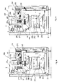
- FIG. 1 illustrates schematically a partially sectioned plan view and with some parts removed for clarity, of an embodiment of a compact packaging system according to the present invention
- FIGS. 2 a , 2 b are schematic frontal and section views of an operating station of the system of FIG. 1 in two different respective functional positions;
- FIG. 3 schematically illustrates a frontal and section view of another operating station of the packaging system of FIG. 1 ;
- FIGS. 4 and 5 illustrate two respective section views according to IV-IV and respectively according to V-V of the same operating station of FIG. 3 , illustrated in two respective different functional positions.
- 1 indicates overall a compact and automatic system particularly designed for packaging, in a protected environment, liquid pharmaceutical products for use in the biotechnological field inside suitable containers 2 and similar, for example, vial, syringes or bottles 2 , according to an embodiment of the invention.
- the system 1 comprises a plurality of operating stations 100 , 200 and 300 connected together and integrated and arranged consecutively in relation to an advancing conveying plane path A of the bottles 2 to be filled, according to a particular configuration, as will be disclosed in detail below.
- all the operating stations 100 , 200 , 300 and corresponding, connecting members 10 , 20 of the system 1 are mounted and arranged on a single platform 3 dimensioned in such a way as to occupy a rectangular area the same as the area of a loading plane of a standard road transport vehicle, so as to be compatible with the loading and conveying of the entire system 1 mounted on the plane, the system 1 , thus all the aforementioned operating stations that compose the latter, is furthermore managed and controlled by a sole control unit (known and not illustrated).
- the system 1 comprises a washing station 100 of empty bottles 2 intended for washing and decontaminating each empty bottle 2 of any organic or inorganic residue present inside the bottle 2 before filling with the liquid product.
- the washing station 100 extends longitudinally on the platform 3 , and has particularly compact dimensions.
- the washing station 100 comprises a conveying plane 50 suitable for defining the inlet of the entire system 1 and on which the empty bottles 2 are deposited to be supplied in an orderly manner along the path A with their open inlets facing upwards, to a conveyor 51 of the belt 52 type wound in a loop and moveable in step mode around a corresponding pulley 53 and supporting a plurality of grasping grippers 54 .
- the grippers 54 temporarily arranged on the lower branch 52 a of the belt 52 are each suitable for grasping by the neck a corresponding bottle 2 from the plane 50 and advancing a corresponding group of bottles 2 until the bottles 2 of the group are turned 180° in relation to the position taken on the plane 50 , namely with their open inlet facing downwards.
- the entire conveyor 51 is suitable for moving by means of a known moving arrangement and which is not illustrated and for example applied to the aforementioned pulleys 53 , vertically downwards (arrows F 1 in FIGS. 2 a and 2 b ) reaching a second operating position R 2 in which each nozzle 55 of a bank 56 of washing nozzles 55 is suitable for being inserted through the open inlet inside a corresponding bottle 2 overturned in such a way as to be able to spray the inside of the bottle 2 with a sterilising washing liquid.
- the removing and grasping position R 1 of a first group of bottles 2 from the plane 50 , and the inserting position R 2 of the nozzles 55 into the bottles 2 of a subsequent group of bottles 2 arranged on the upper branch 52 b and therefore with the washing of the bottles 2 of the this subsequent group are achieved simultaneously with great simplification of movements and overall dimensions.
- the grasping of the aforementioned first group of bottles 2 from the plane 50 by means of the grippers 54 supported by the belt 52 in the position R 1 is achieved during inserting of the nozzles 55 inside the bottles 2 of the subsequent group at the operating position R 2 .
- the station 100 comprises an outlet 57 , at which the washed bottles 2 are unloaded from the conveyor 51 with grippers 54 to be deposited on a connecting conveyor 10 arranged transversely to the plane 50 .
- the conveyor 51 is provided fixed in relation to the bank 56 of nozzles 55 , whilst the latter are fitted movable with reciprocating motion from and to the bottles 2 to be inserted inside the bottles 2 and to achieve the washing thereof.
- the system 1 furthermore comprises a sterilising station 200 , defined by a two-stage sterilising unit 200 , which is also arranged longitudinally on the platform 3 intended for receiving the bottles 2 exiting the station 100 and advanced by the conveyor 10 to carry out the sterilising/depyrogenating of the bottles 2 .
- a sterilising station 200 defined by a two-stage sterilising unit 200 , which is also arranged longitudinally on the platform 3 intended for receiving the bottles 2 exiting the station 100 and advanced by the conveyor 10 to carry out the sterilising/depyrogenating of the bottles 2 .
- the station 200 extends substantially parallel to the washing station 100 and is conveniently arranged in a position laterally alongside the washing station 100 , such that the advancing directions of the bottles 2 along a “U” section of the path A at the two stations 100 and 200 alongside one another are opposite one another.
- the sterilising unit 200 that is the specific subject of a separate patent application filed at the same time as this application by the same applicant, comprises in an embodiment illustrated in FIGS. 1 and 3 , a pair of sterilising modules, respectively a first module 210 and a second module 250 , arranged consecutively and communicating together by means of an intermediate passage 203 .
- modules 210 and 250 of the station 200 are activatable independently of one another according to hot and/or cold sterilising modes of the bottles 2 .
- the modules 210 and 250 by suitably activating in relation to one another the modules 210 and 250 , as will be explained better below, it is possible to achieve excellent sterilisation of the bottles 2 with the following four alternative operating modes: hot-cold, hot-hot, cold-cold, or, lastly, cold-hot.
- the entire unit 200 is enclosed within an insulated covering structure 290 intended for preventing significant heat loss to the external environment.
- the unit 200 furthermore provides a belt conveyor 205 , arranged at the bottom part thereof between a loading inlet 201 , made in the first sterilising module 210 , and an unloading outlet 202 , made in the second sterilising module 250 .
- the conveyor 205 is intended for supporting the bottles 2 on an upper branch 206 thereof to convey the bottles 2 inside and through the first and second module 210 and 250 according to sequences that will be more fully detailed below.
- the loading inlet 201 and the unloading outlet 202 are provided with corresponding gate valves 201 a , 202 a ( FIG. 3 ), suitable for enabling the opening and closing thereof for the respectively passage of the entering and exiting bottles 2 .
- a sterilising chamber 212 is obtained, the lower part of which is crossed by the aforementioned conveyor 205 .
- an air flow F 2 is created that is intended for being blown towards the bottles 2 according to the modes disclosed below to define two different heating or cooling paths of the alternately selectable bottles 2 .
- This flow F 2 flows, above the conveyor 205 , into a bell 230 , below which a filtering element 220 is provided, defined for example by a HEPA filter of suitable class for obtaining the desired degree of air purity.
- a generating device 215 of the aforementioned air flow F 2 is also provided.
- the first 210 and second 250 sterilising modules can have a substantially identical structure: thus, similarly to the first module 210 , also the second module 250 is suitable for defining a corresponding sterilising chamber 252 crossed in the lower part thereof by the aforementioned conveyor 205 , and is provided with a flow generating device 255 for generating an air flow F 3 traversing and flowing into a bell 270 , with a filtering element 260 or HEPA filter.
- the two modules 210 and 250 are arranged specularly so that the aforementioned intermediate passage 203 ( FIG. 1 ) consists of corresponding openings made in the modules 210 , 250 made to match each other.
- both the first module 210 and the second module 250 may both operate as hot or cold sterilisers, as can now be seen in FIGS. 4 and 5 .
- FIG. 4 With which for simplicity and clarity it is intended for disclosing the first module 210 suitable for operating in hot-sterilising mode, in the first module 210 the sterilising chamber 212 is obtained, that is crossed in the lower part thereof by the aforementioned conveyor 205 .
- a path is made for an air flow F 3 intended for being blown towards the bottles 2 in the manner disclosed below and comprising two heating and cooling branches 218 and 219 of the bottles 2 that are selectable alternately.
- This path leads, above the conveyor 205 , into the bell 230 , below which the aforementioned filtering element 220 or HEPA filter is fixed.
- a heating device 211 is located, substantially defined by a coil resistor intended for heating the aforementioned air flow to a preset sterilising/depyrogenating temperature of the bottles 2 .
- the aforementioned generating device 215 of the aforementioned air flow is also provided.
- the generating device 215 comprises an inlet fan 216 , arranged at an air intake 213 and suitable for sucking in air from the external environment, and a main fan 217 , arranged above the aforementioned bell 230 and suitable for conveying the air flow to the bottles 2 through the HEPA filter 220 in a substantially laminar mode.
- the first sterilising module 210 furthermore comprises a refrigerating unit 225 , that is selectively activatable and intended for rapidly cooling the air flow entering the aforementioned first module 210 , when the latter is arranged in the cooling operating mode.
- flow-switching members 221 are provided.
- These substantially comprise a pair of butterfly switches 222 , 223 , that are switchable in push-pull mode between open and closed positions to connect or disconnect corresponding heating branches 218 and cooling branches 219 of the air flow F 2 path.
- an evacuation fan 224 is provided that is intended for conveying part of the circulating air flow to the external environment.
- mixing valve 225 a is associated that is arrangeable in different opening degrees intended for mixing in suitable proportions air coming from the external environment with the part of the air flow that enters the evacuation fan 224 , to lower the temperature of the exiting air.
- the second module 250 defines the sterilising chamber 252 , crossed in the lower part thereof by the aforementioned conveyor 205 .
- a path for an air flow F 3 is made comprising two heating 258 and cooling 259 branches. This path leads, above the conveyor 205 , into the bell 270 , below which the aforementioned HEPA filter 260 is fixed.
- a heating device 251 is arranged, that can be defined by a coil resistor and that is intended for heating the air flow to the aforementioned preset sterilising and depyrogenating temperature of the bottles 2 .
- the generating device 255 comprises an inlet fan 256 , arranged at an air intake 253 and suitable for sucking in air from the external environment, and a main fan 257 , arranged above the aforementioned bell 270 .
- a refrigerating unit 265 is furthermore present that is selectively activatable and is intended for rapidly cooling the air flow F 3 entering thereof the second module 210 , when the latter is arranged in the cooling operating mode.
- flow-switching members 261 are provided.
- These substantially comprise a pair of butterfly switches 262 , 263 , that are switchable in push-pull mode as already disclosed previously.
- an evacuation fan 264 is provided that is intended for conveying part of the flow of circulating air to the external environment.
- a first conveyor 10 is provided, that can be of the known belt type and intended for removing bottles 2 from the outlet of the washing station 100 , already washed and decontaminated, and for conveying the bottles 2 to the inlet 201 of the sterilising station 200 .
- the aforementioned first conveyor 10 is arranged transversely to the orientation of the system 1 , thus defining part of the “U” portion of the aforementioned path A.
- the system 1 furthermore comprises a filling and sealing station 300 for filling the bottles 2 with liquid substances and subsequent for sealing the bottles 2 with corresponding caps, the station 300 is arranged downstream of the aforementioned sterilising station 200 in relation to the path A; this filling and sealing station 300 is substantially aligned on the washing station 100 and is staggered in relation to the outlet line of the sterilising station 200 , defining, together with a second transverse conveyor 20 , a second “L”-shaped portion connected to the aforementioned “U”-shaped portion of the advancing path A of the bottles 2 .
- Such an arrangement enables a particularly compact system configuration to be obtained that makes it possible to contain the external dimensions within the limits set by the work plane of standard means of road transport, as shown above.
- the filling and sealing station 300 is of the known type with linear development and overall comprises a filling unit 301 having a bank 302 of filling nozzles (known and not illustrated in FIG. 1 ), and a sealing cap-supplying and applying device 303 (not shown) arranged along a step-mode filling line defined between two conveyors 304 of the known star type and also provided with two successive weighing device for weighing bottles 2 and with a locking unit 306 of the bottles 2 .
- the filling station 300 can be structurally shaped in a manner similar to the Filling/Capping/Locking machine called “STERIFILL F200” designed and marketed by the same applicant.
- the aforementioned filling and sealing station 300 is directly connected to the sterilising station 200 by the aforementioned second conveyor 20 , of a type similar to the aforementioned first conveyor 10 and it is also transversely arranged.
- the system 1 lastly comprises a sterile chamber 5 that extends above, by covering it, the portion of the system 1 situated downstream of the sterilising station 200 , and namely the second conveyor 20 and the entire filling and sealing station 300 .
- the sterile chamber 5 therefore has an “L” shape with a first branch 5 a arranged transversely and against the sterilising station 200 to enclose the second conveyor 20 , and a second branch 5 b arranged longitudinally at the outlet of the aforementioned filling and sealing station 300 , and therefore of the outlet of the system 1 .
- the sterile chamber 5 is made with substantially known techniques by means of suitable isolating joint panels and is provided with suitable means for providing the regular sterilisation thereof, which is not shown for simplicity as it is completely known.
- the system 1 is assembled as a single and compact body, with sufficient structural rigidity to enable the packaging and conveying thereof without having to dismantle any part.
- This aspect makes the managing of the system easier for the entire productive life thereof.
- the system 1 can in fact be subjected to validation tests directly in the factory, as soon as assembled and then be directly packaged and conveyed to the production site.
- the aforementioned procedure can also be applied whenever it is necessary to move the system 1 to another production site, for example in order to package a different product.
- the configuration of the system therefore fully meets the needs of the modern pharmacological industry and in particular of the companies operating in the biotechnology field.
Abstract
Description
Claims (17)
Applications Claiming Priority (3)
| Application Number | Priority Date | Filing Date | Title |
|---|---|---|---|
| IT000010A ITBO20050010A1 (en) | 2005-01-12 | 2005-01-12 | COMPACT SYSTEM FOR PACKAGING IN STERILE ENVIRONMENT OF LIQUID PRODUCTS INJECTED IN CONTAINERS |
| ITB02005A000010 | 2005-01-12 | ||
| PCT/EP2006/000167 WO2006074904A2 (en) | 2005-01-12 | 2006-01-11 | Compact system for packaging injectable liquid products into containers in a sterile environment |
Publications (2)
| Publication Number | Publication Date |
|---|---|
| US20080141622A1 US20080141622A1 (en) | 2008-06-19 |
| US7581367B2 true US7581367B2 (en) | 2009-09-01 |
Family
ID=36237422
Family Applications (1)
| Application Number | Title | Priority Date | Filing Date |
|---|---|---|---|
| US11/795,133 Active US7581367B2 (en) | 2005-01-12 | 2006-01-11 | Compact system for packaging injectable liquid products into containers in a sterile environment |
Country Status (6)
| Country | Link |
|---|---|
| US (1) | US7581367B2 (en) |
| EP (1) | EP1841655B1 (en) |
| DE (1) | DE602006008892D1 (en) |
| ES (1) | ES2331626T3 (en) |
| IT (1) | ITBO20050010A1 (en) |
| WO (1) | WO2006074904A2 (en) |
Cited By (3)
| Publication number | Priority date | Publication date | Assignee | Title |
|---|---|---|---|---|
| US20080260609A1 (en) * | 2005-01-12 | 2008-10-23 | Claudio Bechini | Unit for Sterilising and Depyrogenating Containers |
| US20110302881A1 (en) * | 2010-06-14 | 2011-12-15 | Conteno | Transportable bottling plant in a container |
| WO2013155369A1 (en) * | 2012-04-13 | 2013-10-17 | Py Daniel C | Modular filling apparatus and method |
Families Citing this family (14)
| Publication number | Priority date | Publication date | Assignee | Title |
|---|---|---|---|---|
| US8336700B2 (en) | 2009-04-08 | 2012-12-25 | Ima North America, Inc. | Transport system for moving a plurality of containers through a plurality of work stations |
| DE102009040924A1 (en) * | 2009-09-11 | 2011-03-24 | Khs Gmbh | Plant for the sterile filling of products, in particular of drinks in bottles or similar containers |
| JP5806232B2 (en) * | 2009-12-21 | 2015-11-10 | エーティーエムアイ ビーヴィービーエー | Disposable production line |
| DE102010032601A1 (en) * | 2010-07-28 | 2012-02-02 | Krones Aktiengesellschaft | Linear sterilization module for use in container treatment machine for sterilizing container that is utilized for storing of food in food packaging industry, has treatment elements for moving along with container |
| CN102145871B (en) * | 2011-03-21 | 2012-08-29 | 楚天科技股份有限公司 | Capping machine |
| SG10201406761SA (en) | 2013-10-18 | 2015-05-28 | Pall Life Sciences Belgium Bvba | Disposable production line for filling and finishing a product |
| US20150282497A1 (en) * | 2014-04-03 | 2015-10-08 | Clint Arthur | Portion control for individualized servings of butter and the like |
| FR3020800B1 (en) * | 2014-05-09 | 2017-08-25 | Pierre Fabre Dermo-Cosmetique | DEVICE AND METHOD FOR ASEPTIC FILLING |
| CN104528620B (en) * | 2014-11-25 | 2017-02-22 | 启东翔龙旅游开发有限公司 | Method for performing correction, pushing, rinsing, feeding, conveying and loading on loading bottle, conveying cover and conveying gasket |
| CN104528619B (en) * | 2014-11-25 | 2017-02-22 | 石家庄九鼎动物药业有限公司 | Method for performing correction, pushing, rinsing, feeding, conveying and loading on loading bottle, conveying cover, conveying gasket, and performing impact extrusion |
| CN104608973B (en) * | 2015-01-28 | 2016-09-07 | 四川科伦药业股份有限公司 | A kind of Full Automatic Liquid liquid multi-chamber-bag bag making, filling and sealing machine |
| CN105599937B (en) * | 2016-03-09 | 2018-02-27 | 四川科伦药业股份有限公司 | A kind of Full Automatic Liquid liquid douche bag bag making, filling and sealing machine |
| ES2684403B1 (en) | 2017-03-31 | 2019-07-09 | Farm Rovi Lab Sa | PROCEDURE FOR GRAVIMETRIC FILLING IN STERILE SOLID CONDITIONS IN A PHARMACEUTICAL CONTAINER AND PHARMACEUTICAL CONTAINER USED IN THE SAME |
| DE102018126863A1 (en) * | 2018-10-26 | 2020-04-30 | Krones Ag | Arrangement for treating containers |
Citations (22)
| Publication number | Priority date | Publication date | Assignee | Title |
|---|---|---|---|---|
| US599205A (en) * | 1898-02-15 | vause | ||
| US3747296A (en) * | 1971-12-06 | 1973-07-24 | Zausner Foods Corp | Sterilizing device for filling machines |
| US4296068A (en) * | 1979-02-19 | 1981-10-20 | Dai Nippon Insatsu Kabushiki Kaisha | Apparatus for sterilizing a succession of food containers or the like |
| US4533515A (en) * | 1980-11-22 | 1985-08-06 | Papier-Und Kunststoff-Werke Linnich Gmbh | Method employing steam to sterilize packaging material |
| US4707334A (en) * | 1985-06-27 | 1987-11-17 | Kolubus Gmbh & Co. Kg | Isolation method and apparatus for sterilizing chambers of filling machines |
| US4862933A (en) * | 1987-05-14 | 1989-09-05 | Muller Gmbh & Co. Kg. | Doser for sterilizer of a packaging system |
| US4979347A (en) * | 1988-05-19 | 1990-12-25 | Snow Brand Milk Products Co., Ltd. | Fill- and pack in a non-germ atmosphere machine |
| US5129212A (en) * | 1990-11-08 | 1992-07-14 | Liqui-Box/B-Bar-B Corporation | Method and apparatus for automatically filling and sterilizing containers |
| US5135014A (en) | 1990-05-02 | 1992-08-04 | The West Company, Incorporated | Bottle washer with multiple size carrier |
| US5178841A (en) * | 1990-10-13 | 1993-01-12 | Fmc Corporation | Sterilizing apparatus |
| US5258162A (en) * | 1989-11-07 | 1993-11-02 | Tetra Alfa Holdings S.A. | Method of producing a gaseous hydrogen peroxide-containing sterilization fluid |
| US5368828A (en) * | 1992-11-12 | 1994-11-29 | Tetra Laval Holdings & Finance S.A. | Method and apparatus for carton sterilization |
| US5377475A (en) * | 1992-06-10 | 1995-01-03 | Robert Bosch Gmbh | Device for sterilizing packaging containers |
| US5896899A (en) | 1993-08-07 | 1999-04-27 | Krones Ag Hermann Kronseder Maschinenfabrik | Method and an apparatus for sterile bottling of beverages |
| US6039922A (en) * | 1997-08-15 | 2000-03-21 | Tetra Laval Holdings & Finance, Sa | UV radiation and vapor-phase hydrogen peroxide sterilization packaging |
| US6120730A (en) * | 1998-06-26 | 2000-09-19 | Tetra Laval Holdings & Finance, Sa | Heat and hydrogen peroxide gas sterilization of container |
| US6185910B1 (en) * | 1997-07-24 | 2001-02-13 | Krones Ag | Method and an apparatus for high-purity bottling of beverages |
| US20010029999A1 (en) | 2000-03-03 | 2001-10-18 | Hamba-Maschinenfabrik Hans A. Muller Gmbh & Co. Kg | Machine for filling bottles with liquid |
| US6436343B1 (en) * | 1997-04-28 | 2002-08-20 | Libra Pharmaceutical Technologies | Method for the cold sterilization of a tunnel-type oven for pharmaceutical use, and oven for carrying out said method |
| US6475435B1 (en) * | 1999-02-02 | 2002-11-05 | Steuben Foods Incorporated | Apparatus and method for providing sterilization zones in an aseptic packaging sterilization tunnel |
| DE202004001619U1 (en) | 2004-02-04 | 2004-05-19 | Khs Maschinen- Und Anlagenbau Ag | Plant for filling bottles under aseptic conditions with foodstuffs or pharmaceuticals comprises filling machine and sealing machine in clean room environment, each machine having housing connected to air outlet |
| US7357159B2 (en) * | 2003-12-11 | 2008-04-15 | Popplau Jens H | Container treatment device with a gas curtain |
-
2005
- 2005-01-12 IT IT000010A patent/ITBO20050010A1/en unknown
-
2006
- 2006-01-11 WO PCT/EP2006/000167 patent/WO2006074904A2/en active Application Filing
- 2006-01-11 ES ES06700361T patent/ES2331626T3/en active Active
- 2006-01-11 EP EP06700361A patent/EP1841655B1/en active Active
- 2006-01-11 US US11/795,133 patent/US7581367B2/en active Active
- 2006-01-11 DE DE602006008892T patent/DE602006008892D1/en active Active
Patent Citations (22)
| Publication number | Priority date | Publication date | Assignee | Title |
|---|---|---|---|---|
| US599205A (en) * | 1898-02-15 | vause | ||
| US3747296A (en) * | 1971-12-06 | 1973-07-24 | Zausner Foods Corp | Sterilizing device for filling machines |
| US4296068A (en) * | 1979-02-19 | 1981-10-20 | Dai Nippon Insatsu Kabushiki Kaisha | Apparatus for sterilizing a succession of food containers or the like |
| US4533515A (en) * | 1980-11-22 | 1985-08-06 | Papier-Und Kunststoff-Werke Linnich Gmbh | Method employing steam to sterilize packaging material |
| US4707334A (en) * | 1985-06-27 | 1987-11-17 | Kolubus Gmbh & Co. Kg | Isolation method and apparatus for sterilizing chambers of filling machines |
| US4862933A (en) * | 1987-05-14 | 1989-09-05 | Muller Gmbh & Co. Kg. | Doser for sterilizer of a packaging system |
| US4979347A (en) * | 1988-05-19 | 1990-12-25 | Snow Brand Milk Products Co., Ltd. | Fill- and pack in a non-germ atmosphere machine |
| US5258162A (en) * | 1989-11-07 | 1993-11-02 | Tetra Alfa Holdings S.A. | Method of producing a gaseous hydrogen peroxide-containing sterilization fluid |
| US5135014A (en) | 1990-05-02 | 1992-08-04 | The West Company, Incorporated | Bottle washer with multiple size carrier |
| US5178841A (en) * | 1990-10-13 | 1993-01-12 | Fmc Corporation | Sterilizing apparatus |
| US5129212A (en) * | 1990-11-08 | 1992-07-14 | Liqui-Box/B-Bar-B Corporation | Method and apparatus for automatically filling and sterilizing containers |
| US5377475A (en) * | 1992-06-10 | 1995-01-03 | Robert Bosch Gmbh | Device for sterilizing packaging containers |
| US5368828A (en) * | 1992-11-12 | 1994-11-29 | Tetra Laval Holdings & Finance S.A. | Method and apparatus for carton sterilization |
| US5896899A (en) | 1993-08-07 | 1999-04-27 | Krones Ag Hermann Kronseder Maschinenfabrik | Method and an apparatus for sterile bottling of beverages |
| US6436343B1 (en) * | 1997-04-28 | 2002-08-20 | Libra Pharmaceutical Technologies | Method for the cold sterilization of a tunnel-type oven for pharmaceutical use, and oven for carrying out said method |
| US6185910B1 (en) * | 1997-07-24 | 2001-02-13 | Krones Ag | Method and an apparatus for high-purity bottling of beverages |
| US6039922A (en) * | 1997-08-15 | 2000-03-21 | Tetra Laval Holdings & Finance, Sa | UV radiation and vapor-phase hydrogen peroxide sterilization packaging |
| US6120730A (en) * | 1998-06-26 | 2000-09-19 | Tetra Laval Holdings & Finance, Sa | Heat and hydrogen peroxide gas sterilization of container |
| US6475435B1 (en) * | 1999-02-02 | 2002-11-05 | Steuben Foods Incorporated | Apparatus and method for providing sterilization zones in an aseptic packaging sterilization tunnel |
| US20010029999A1 (en) | 2000-03-03 | 2001-10-18 | Hamba-Maschinenfabrik Hans A. Muller Gmbh & Co. Kg | Machine for filling bottles with liquid |
| US7357159B2 (en) * | 2003-12-11 | 2008-04-15 | Popplau Jens H | Container treatment device with a gas curtain |
| DE202004001619U1 (en) | 2004-02-04 | 2004-05-19 | Khs Maschinen- Und Anlagenbau Ag | Plant for filling bottles under aseptic conditions with foodstuffs or pharmaceuticals comprises filling machine and sealing machine in clean room environment, each machine having housing connected to air outlet |
Non-Patent Citations (1)
| Title |
|---|
| International Search Report for PCT/EP2006/000167 mailed Jun. 28, 2006. |
Cited By (10)
| Publication number | Priority date | Publication date | Assignee | Title |
|---|---|---|---|---|
| US20080260609A1 (en) * | 2005-01-12 | 2008-10-23 | Claudio Bechini | Unit for Sterilising and Depyrogenating Containers |
| US7811533B2 (en) * | 2005-01-12 | 2010-10-12 | I.M.A. Industria Macchine Automatiche S.P.A. | Unit for sterilising and depyrogenating containers |
| US20110302881A1 (en) * | 2010-06-14 | 2011-12-15 | Conteno | Transportable bottling plant in a container |
| US8479475B2 (en) * | 2010-06-14 | 2013-07-09 | Conteno | Transportable bottling plant in a container |
| WO2013155369A1 (en) * | 2012-04-13 | 2013-10-17 | Py Daniel C | Modular filling apparatus and method |
| US8966866B2 (en) | 2012-04-13 | 2015-03-03 | Dr. Py Institute Llc | Modular filling apparatus and method |
| CN104507815A (en) * | 2012-04-13 | 2015-04-08 | 皮博士研究所有限责任公司 | Modular filling apparatus and method |
| US20150175281A1 (en) * | 2012-04-13 | 2015-06-25 | Dr. Py Institute Llc | Modular Filling Apparatus and Method |
| CN104507815B (en) * | 2012-04-13 | 2017-06-09 | 皮博士研究所有限责任公司 | Modularization pad device and method |
| US10273025B2 (en) * | 2012-04-13 | 2019-04-30 | Dr. Py Institute Llc | Modular filling apparatus and method |
Also Published As
| Publication number | Publication date |
|---|---|
| EP1841655A2 (en) | 2007-10-10 |
| US20080141622A1 (en) | 2008-06-19 |
| ITBO20050010A1 (en) | 2006-07-13 |
| EP1841655B1 (en) | 2009-09-02 |
| DE602006008892D1 (en) | 2009-10-15 |
| WO2006074904A2 (en) | 2006-07-20 |
| ES2331626T3 (en) | 2010-01-11 |
| WO2006074904A3 (en) | 2006-08-31 |
Similar Documents
| Publication | Publication Date | Title |
|---|---|---|
| US7581367B2 (en) | Compact system for packaging injectable liquid products into containers in a sterile environment | |
| US6351924B1 (en) | Method and device for sterilizing and filling packing containers | |
| US7536839B2 (en) | Method and machine for closing bottle with sterile caps | |
| FI94331B (en) | Method and apparatus for sterilizing a container provided with a filling opening | |
| KR20190095339A (en) | Component assembly of containment means for automated production of pharmaceutical or biotechnological articles | |
| JP2662872B2 (en) | Fluid product valve device and device for using it to send fluid product to its processing operation | |
| CN103566387B (en) | It is used for processing the apparatus and method of container lid | |
| AU2006222941C1 (en) | Sterile de-molding apparatus and method | |
| CN102529070B (en) | Transfer starwheel in a clean room | |
| US4590734A (en) | Packaging machine | |
| CN101795716A (en) | The active sterilization zone that is used for container filling | |
| US20060075721A1 (en) | Machine for packaging products in a protected environment | |
| SE462740B (en) | DISC AND CLEANING SYSTEM FOR A PACKAGING MACHINE | |
| CN102802822A (en) | Device and method for filling or packing contents into containers in a sterile manner | |
| EP1838465B1 (en) | Unit for washing containers | |
| US7811533B2 (en) | Unit for sterilising and depyrogenating containers | |
| JPH08219346A (en) | Automatic pipeline connecting device | |
| JPH0629080B2 (en) | Aseptic filling device | |
| JPH01182226A (en) | Aseptic filling machine | |
| JP7299490B2 (en) | Goods transport system | |
| IT201900010134A1 (en) | RECIPIENT TREATMENT PLANT SUITABLE TO CONTAIN A VERSABLE PRODUCT | |
| JP6651696B2 (en) | Container sterilization method and device | |
| EP4108627A1 (en) | Apparatus for packaging a pourable product | |
| BEEN | Operation and Validation Technology of Blow Fill Seal | |
| BEEN | Operation and Validation of |
Legal Events
| Date | Code | Title | Description |
|---|---|---|---|
| AS | Assignment |
Owner name: IMA INDUSTRIA MACCHINE AUTOMATICHE S.P.A., ITALY Free format text: ASSIGNMENT OF ASSIGNORS INTEREST;ASSIGNOR:BECHINI, CLAUDIO;REEL/FRAME:020651/0976 Effective date: 20080214 |
|
| AS | Assignment |
Owner name: IMA LIFE S.R.L., ITALY Free format text: RATIFICATION OF AGREEMENT;ASSIGNOR:I.M.A. INDUSTRIA MACCHINE AUTOMATICHE S.P.A.;REEL/FRAME:022092/0918 Effective date: 20081116 Owner name: IMA LIFE S.R.L.,ITALY Free format text: RATIFICATION OF AGREEMENT;ASSIGNOR:I.M.A. INDUSTRIA MACCHINE AUTOMATICHE S.P.A.;REEL/FRAME:022092/0918 Effective date: 20081116 |
|
| STCF | Information on status: patent grant |
Free format text: PATENTED CASE |
|
| CC | Certificate of correction | ||
| FPAY | Fee payment |
Year of fee payment: 4 |
|
| FPAY | Fee payment |
Year of fee payment: 8 |
|
| MAFP | Maintenance fee payment |
Free format text: PAYMENT OF MAINTENANCE FEE, 12TH YEAR, LARGE ENTITY (ORIGINAL EVENT CODE: M1553); ENTITY STATUS OF PATENT OWNER: LARGE ENTITY Year of fee payment: 12 |