US7559941B2 - Instrument for delivery of implant - Google Patents
Instrument for delivery of implant Download PDFInfo
- Publication number
- US7559941B2 US7559941B2 US10/742,020 US74202003A US7559941B2 US 7559941 B2 US7559941 B2 US 7559941B2 US 74202003 A US74202003 A US 74202003A US 7559941 B2 US7559941 B2 US 7559941B2
- Authority
- US
- United States
- Prior art keywords
- distal end
- instrument
- slide member
- implant
- main shaft
- Prior art date
- Legal status (The legal status is an assumption and is not a legal conclusion. Google has not performed a legal analysis and makes no representation as to the accuracy of the status listed.)
- Active, expires
Links
- 239000007943 implant Substances 0.000 title claims abstract description 149
- 230000033001 locomotion Effects 0.000 claims description 2
- 230000001012 protector Effects 0.000 abstract description 39
- 210000001519 tissue Anatomy 0.000 description 39
- 238000000034 method Methods 0.000 description 15
- 238000001356 surgical procedure Methods 0.000 description 15
- 230000005499 meniscus Effects 0.000 description 14
- 230000008439 repair process Effects 0.000 description 13
- 230000006378 damage Effects 0.000 description 11
- 230000008929 regeneration Effects 0.000 description 7
- 238000011069 regeneration method Methods 0.000 description 7
- 210000004872 soft tissue Anatomy 0.000 description 7
- 210000000988 bone and bone Anatomy 0.000 description 6
- 210000000845 cartilage Anatomy 0.000 description 6
- 208000014674 injury Diseases 0.000 description 6
- 210000003127 knee Anatomy 0.000 description 6
- 230000007850 degeneration Effects 0.000 description 5
- 210000000968 fibrocartilage Anatomy 0.000 description 5
- 210000002435 tendon Anatomy 0.000 description 5
- 208000027418 Wounds and injury Diseases 0.000 description 4
- 201000010099 disease Diseases 0.000 description 4
- 208000037265 diseases, disorders, signs and symptoms Diseases 0.000 description 4
- 239000000463 material Substances 0.000 description 4
- 210000000513 rotator cuff Anatomy 0.000 description 4
- 230000032683 aging Effects 0.000 description 3
- 230000007423 decrease Effects 0.000 description 3
- 210000001503 joint Anatomy 0.000 description 3
- 102000010834 Extracellular Matrix Proteins Human genes 0.000 description 2
- 108010037362 Extracellular Matrix Proteins Proteins 0.000 description 2
- 241000283984 Rodentia Species 0.000 description 2
- 238000007792 addition Methods 0.000 description 2
- 230000002411 adverse Effects 0.000 description 2
- 210000002744 extracellular matrix Anatomy 0.000 description 2
- 210000003035 hyaline cartilage Anatomy 0.000 description 2
- 210000003041 ligament Anatomy 0.000 description 2
- 238000012986 modification Methods 0.000 description 2
- 230000004048 modification Effects 0.000 description 2
- 210000003205 muscle Anatomy 0.000 description 2
- 210000004417 patella Anatomy 0.000 description 2
- 210000000323 shoulder joint Anatomy 0.000 description 2
- 239000010421 standard material Substances 0.000 description 2
- 210000001738 temporomandibular joint Anatomy 0.000 description 2
- 239000002407 tissue scaffold Substances 0.000 description 2
- 230000008733 trauma Effects 0.000 description 2
- 230000002792 vascular Effects 0.000 description 2
- 208000024288 Rotator Cuff injury Diseases 0.000 description 1
- 208000026137 Soft tissue injury Diseases 0.000 description 1
- 238000005299 abrasion Methods 0.000 description 1
- 229920000122 acrylonitrile butadiene styrene Polymers 0.000 description 1
- 230000002917 arthritic effect Effects 0.000 description 1
- 230000000712 assembly Effects 0.000 description 1
- 238000000429 assembly Methods 0.000 description 1
- 239000012867 bioactive agent Substances 0.000 description 1
- 230000015556 catabolic process Effects 0.000 description 1
- 210000004027 cell Anatomy 0.000 description 1
- 239000003795 chemical substances by application Substances 0.000 description 1
- 230000000295 complement effect Effects 0.000 description 1
- 230000032798 delamination Effects 0.000 description 1
- 230000000694 effects Effects 0.000 description 1
- 210000003414 extremity Anatomy 0.000 description 1
- 239000000835 fiber Substances 0.000 description 1
- 210000003811 finger Anatomy 0.000 description 1
- 238000007373 indentation Methods 0.000 description 1
- 229910010272 inorganic material Inorganic materials 0.000 description 1
- 239000011147 inorganic material Substances 0.000 description 1
- 238000003780 insertion Methods 0.000 description 1
- 230000037431 insertion Effects 0.000 description 1
- 210000000629 knee joint Anatomy 0.000 description 1
- 230000003902 lesion Effects 0.000 description 1
- 230000007774 longterm Effects 0.000 description 1
- 239000000314 lubricant Substances 0.000 description 1
- 238000002324 minimally invasive surgery Methods 0.000 description 1
- 238000012829 orthopaedic surgery Methods 0.000 description 1
- 229920003023 plastic Polymers 0.000 description 1
- 230000001172 regenerating effect Effects 0.000 description 1
- 230000003252 repetitive effect Effects 0.000 description 1
- 238000000926 separation method Methods 0.000 description 1
- 210000000813 small intestine Anatomy 0.000 description 1
- 230000000087 stabilizing effect Effects 0.000 description 1
- 210000004876 tela submucosa Anatomy 0.000 description 1
- 210000003813 thumb Anatomy 0.000 description 1
Images


Classifications
-
- A—HUMAN NECESSITIES
- A61—MEDICAL OR VETERINARY SCIENCE; HYGIENE
- A61F—FILTERS IMPLANTABLE INTO BLOOD VESSELS; PROSTHESES; DEVICES PROVIDING PATENCY TO, OR PREVENTING COLLAPSING OF, TUBULAR STRUCTURES OF THE BODY, e.g. STENTS; ORTHOPAEDIC, NURSING OR CONTRACEPTIVE DEVICES; FOMENTATION; TREATMENT OR PROTECTION OF EYES OR EARS; BANDAGES, DRESSINGS OR ABSORBENT PADS; FIRST-AID KITS
- A61F2/00—Filters implantable into blood vessels; Prostheses, i.e. artificial substitutes or replacements for parts of the body; Appliances for connecting them with the body; Devices providing patency to, or preventing collapsing of, tubular structures of the body, e.g. stents
- A61F2/02—Prostheses implantable into the body
- A61F2/30—Joints
- A61F2/46—Special tools or methods for implanting or extracting artificial joints, accessories, bone grafts or substitutes, or particular adaptations therefor
- A61F2/4603—Special tools or methods for implanting or extracting artificial joints, accessories, bone grafts or substitutes, or particular adaptations therefor for insertion or extraction of endoprosthetic joints or of accessories thereof
- A61F2/4618—Special tools or methods for implanting or extracting artificial joints, accessories, bone grafts or substitutes, or particular adaptations therefor for insertion or extraction of endoprosthetic joints or of accessories thereof of cartilage
-
- A—HUMAN NECESSITIES
- A61—MEDICAL OR VETERINARY SCIENCE; HYGIENE
- A61B—DIAGNOSIS; SURGERY; IDENTIFICATION
- A61B17/00—Surgical instruments, devices or methods, e.g. tourniquets
- A61B17/28—Surgical forceps
- A61B17/29—Forceps for use in minimally invasive surgery
-
- A—HUMAN NECESSITIES
- A61—MEDICAL OR VETERINARY SCIENCE; HYGIENE
- A61B—DIAGNOSIS; SURGERY; IDENTIFICATION
- A61B17/00—Surgical instruments, devices or methods, e.g. tourniquets
- A61B17/34—Trocars; Puncturing needles
- A61B17/3468—Trocars; Puncturing needles for implanting or removing devices, e.g. prostheses, implants, seeds, wires
-
- A—HUMAN NECESSITIES
- A61—MEDICAL OR VETERINARY SCIENCE; HYGIENE
- A61B—DIAGNOSIS; SURGERY; IDENTIFICATION
- A61B17/00—Surgical instruments, devices or methods, e.g. tourniquets
- A61B17/00234—Surgical instruments, devices or methods, e.g. tourniquets for minimally invasive surgery
- A61B2017/00238—Type of minimally invasive operation
- A61B2017/00261—Discectomy
-
- A—HUMAN NECESSITIES
- A61—MEDICAL OR VETERINARY SCIENCE; HYGIENE
- A61B—DIAGNOSIS; SURGERY; IDENTIFICATION
- A61B17/00—Surgical instruments, devices or methods, e.g. tourniquets
- A61B17/00234—Surgical instruments, devices or methods, e.g. tourniquets for minimally invasive surgery
- A61B2017/00353—Surgical instruments, devices or methods, e.g. tourniquets for minimally invasive surgery one mechanical instrument performing multiple functions, e.g. cutting and grasping
-
- A—HUMAN NECESSITIES
- A61—MEDICAL OR VETERINARY SCIENCE; HYGIENE
- A61B—DIAGNOSIS; SURGERY; IDENTIFICATION
- A61B17/00—Surgical instruments, devices or methods, e.g. tourniquets
- A61B2017/00969—Surgical instruments, devices or methods, e.g. tourniquets used for transplantation
-
- A—HUMAN NECESSITIES
- A61—MEDICAL OR VETERINARY SCIENCE; HYGIENE
- A61B—DIAGNOSIS; SURGERY; IDENTIFICATION
- A61B17/00—Surgical instruments, devices or methods, e.g. tourniquets
- A61B17/28—Surgical forceps
- A61B17/29—Forceps for use in minimally invasive surgery
- A61B2017/2926—Details of heads or jaws
- A61B2017/2932—Transmission of forces to jaw members
- A61B2017/2944—Translation of jaw members
-
- A—HUMAN NECESSITIES
- A61—MEDICAL OR VETERINARY SCIENCE; HYGIENE
- A61F—FILTERS IMPLANTABLE INTO BLOOD VESSELS; PROSTHESES; DEVICES PROVIDING PATENCY TO, OR PREVENTING COLLAPSING OF, TUBULAR STRUCTURES OF THE BODY, e.g. STENTS; ORTHOPAEDIC, NURSING OR CONTRACEPTIVE DEVICES; FOMENTATION; TREATMENT OR PROTECTION OF EYES OR EARS; BANDAGES, DRESSINGS OR ABSORBENT PADS; FIRST-AID KITS
- A61F2/00—Filters implantable into blood vessels; Prostheses, i.e. artificial substitutes or replacements for parts of the body; Appliances for connecting them with the body; Devices providing patency to, or preventing collapsing of, tubular structures of the body, e.g. stents
- A61F2/02—Prostheses implantable into the body
- A61F2/30—Joints
- A61F2/38—Joints for elbows or knees
- A61F2/3872—Meniscus for implantation between the natural bone surfaces
-
- A—HUMAN NECESSITIES
- A61—MEDICAL OR VETERINARY SCIENCE; HYGIENE
- A61F—FILTERS IMPLANTABLE INTO BLOOD VESSELS; PROSTHESES; DEVICES PROVIDING PATENCY TO, OR PREVENTING COLLAPSING OF, TUBULAR STRUCTURES OF THE BODY, e.g. STENTS; ORTHOPAEDIC, NURSING OR CONTRACEPTIVE DEVICES; FOMENTATION; TREATMENT OR PROTECTION OF EYES OR EARS; BANDAGES, DRESSINGS OR ABSORBENT PADS; FIRST-AID KITS
- A61F2/00—Filters implantable into blood vessels; Prostheses, i.e. artificial substitutes or replacements for parts of the body; Appliances for connecting them with the body; Devices providing patency to, or preventing collapsing of, tubular structures of the body, e.g. stents
- A61F2/02—Prostheses implantable into the body
- A61F2/30—Joints
- A61F2002/30001—Additional features of subject-matter classified in A61F2/28, A61F2/30 and subgroups thereof
- A61F2002/30316—The prosthesis having different structural features at different locations within the same prosthesis; Connections between prosthetic parts; Special structural features of bone or joint prostheses not otherwise provided for
- A61F2002/30329—Connections or couplings between prosthetic parts, e.g. between modular parts; Connecting elements
- A61F2002/30471—Connections or couplings between prosthetic parts, e.g. between modular parts; Connecting elements connected by a hinged linkage mechanism, e.g. of the single-bar or multi-bar linkage type
-
- A—HUMAN NECESSITIES
- A61—MEDICAL OR VETERINARY SCIENCE; HYGIENE
- A61F—FILTERS IMPLANTABLE INTO BLOOD VESSELS; PROSTHESES; DEVICES PROVIDING PATENCY TO, OR PREVENTING COLLAPSING OF, TUBULAR STRUCTURES OF THE BODY, e.g. STENTS; ORTHOPAEDIC, NURSING OR CONTRACEPTIVE DEVICES; FOMENTATION; TREATMENT OR PROTECTION OF EYES OR EARS; BANDAGES, DRESSINGS OR ABSORBENT PADS; FIRST-AID KITS
- A61F2/00—Filters implantable into blood vessels; Prostheses, i.e. artificial substitutes or replacements for parts of the body; Appliances for connecting them with the body; Devices providing patency to, or preventing collapsing of, tubular structures of the body, e.g. stents
- A61F2/02—Prostheses implantable into the body
- A61F2/30—Joints
- A61F2002/30001—Additional features of subject-matter classified in A61F2/28, A61F2/30 and subgroups thereof
- A61F2002/30316—The prosthesis having different structural features at different locations within the same prosthesis; Connections between prosthetic parts; Special structural features of bone or joint prostheses not otherwise provided for
- A61F2002/30329—Connections or couplings between prosthetic parts, e.g. between modular parts; Connecting elements
- A61F2002/30518—Connections or couplings between prosthetic parts, e.g. between modular parts; Connecting elements with possibility of relative movement between the prosthetic parts
- A61F2002/3052—Connections or couplings between prosthetic parts, e.g. between modular parts; Connecting elements with possibility of relative movement between the prosthetic parts unrestrained in only one direction, e.g. moving unidirectionally
- A61F2002/30522—Connections or couplings between prosthetic parts, e.g. between modular parts; Connecting elements with possibility of relative movement between the prosthetic parts unrestrained in only one direction, e.g. moving unidirectionally releasable, e.g. using a releasable ratchet
-
- A—HUMAN NECESSITIES
- A61—MEDICAL OR VETERINARY SCIENCE; HYGIENE
- A61F—FILTERS IMPLANTABLE INTO BLOOD VESSELS; PROSTHESES; DEVICES PROVIDING PATENCY TO, OR PREVENTING COLLAPSING OF, TUBULAR STRUCTURES OF THE BODY, e.g. STENTS; ORTHOPAEDIC, NURSING OR CONTRACEPTIVE DEVICES; FOMENTATION; TREATMENT OR PROTECTION OF EYES OR EARS; BANDAGES, DRESSINGS OR ABSORBENT PADS; FIRST-AID KITS
- A61F2/00—Filters implantable into blood vessels; Prostheses, i.e. artificial substitutes or replacements for parts of the body; Appliances for connecting them with the body; Devices providing patency to, or preventing collapsing of, tubular structures of the body, e.g. stents
- A61F2/02—Prostheses implantable into the body
- A61F2/30—Joints
- A61F2/46—Special tools or methods for implanting or extracting artificial joints, accessories, bone grafts or substitutes, or particular adaptations therefor
- A61F2/4603—Special tools or methods for implanting or extracting artificial joints, accessories, bone grafts or substitutes, or particular adaptations therefor for insertion or extraction of endoprosthetic joints or of accessories thereof
- A61F2002/4622—Special tools or methods for implanting or extracting artificial joints, accessories, bone grafts or substitutes, or particular adaptations therefor for insertion or extraction of endoprosthetic joints or of accessories thereof having the shape of a forceps or a clamp
-
- A—HUMAN NECESSITIES
- A61—MEDICAL OR VETERINARY SCIENCE; HYGIENE
- A61F—FILTERS IMPLANTABLE INTO BLOOD VESSELS; PROSTHESES; DEVICES PROVIDING PATENCY TO, OR PREVENTING COLLAPSING OF, TUBULAR STRUCTURES OF THE BODY, e.g. STENTS; ORTHOPAEDIC, NURSING OR CONTRACEPTIVE DEVICES; FOMENTATION; TREATMENT OR PROTECTION OF EYES OR EARS; BANDAGES, DRESSINGS OR ABSORBENT PADS; FIRST-AID KITS
- A61F2/00—Filters implantable into blood vessels; Prostheses, i.e. artificial substitutes or replacements for parts of the body; Appliances for connecting them with the body; Devices providing patency to, or preventing collapsing of, tubular structures of the body, e.g. stents
- A61F2/02—Prostheses implantable into the body
- A61F2/30—Joints
- A61F2/46—Special tools or methods for implanting or extracting artificial joints, accessories, bone grafts or substitutes, or particular adaptations therefor
- A61F2002/4635—Special tools or methods for implanting or extracting artificial joints, accessories, bone grafts or substitutes, or particular adaptations therefor using minimally invasive surgery
-
- A—HUMAN NECESSITIES
- A61—MEDICAL OR VETERINARY SCIENCE; HYGIENE
- A61F—FILTERS IMPLANTABLE INTO BLOOD VESSELS; PROSTHESES; DEVICES PROVIDING PATENCY TO, OR PREVENTING COLLAPSING OF, TUBULAR STRUCTURES OF THE BODY, e.g. STENTS; ORTHOPAEDIC, NURSING OR CONTRACEPTIVE DEVICES; FOMENTATION; TREATMENT OR PROTECTION OF EYES OR EARS; BANDAGES, DRESSINGS OR ABSORBENT PADS; FIRST-AID KITS
- A61F2220/00—Fixations or connections for prostheses classified in groups A61F2/00 - A61F2/26 or A61F2/82 or A61F9/00 or A61F11/00 or subgroups thereof
- A61F2220/0025—Connections or couplings between prosthetic parts, e.g. between modular parts; Connecting elements
- A61F2220/0091—Connections or couplings between prosthetic parts, e.g. between modular parts; Connecting elements connected by a hinged linkage mechanism, e.g. of the single-bar or multi-bar linkage type
Definitions
- the present invention relates generally to a surgical instrument for delivering an implant to a damaged tissue site in the human body.
- a joint can include articular hyaline cartilage, intra-articular fibrocartilage, tendons and ligaments.
- Articular hyaline cartilage is found on the surfaces of the bones of the joint.
- Intra-articular cartilage is found between the joint surfaces.
- Tendons connect muscle to the bones of the joint, and ligaments connect articular extremities of the bones of the joint.
- Soft tissue health can be adversely affected by disease, aging, or trauma.
- the adverse effects of disease, aging and trauma can be, for example, in the form of a tear in the soft tissue, or in the form of a breakdown, thinning or delamination of the tissue.
- meniscus of the knee One form of intra-articular cartilage that is frequently damaged or degenerated is the meniscus of the knee.
- the meniscus is frequently damaged in twisting injuries. It is also damaged with repetitive impact over time. Meniscus degeneration can also occur by aging; as a person ages, the meniscus can become soft in places, so that even common motions like squatting can cause meniscal tears.
- a tear repair is most commonly performed when the tear is a clean longitudinal vertical lesion in the vascular red zone of the meniscus.
- the basic strategy is to stabilize the tear by limiting or eliminating radial separation of the faces of the tear when the meniscus is load bearing.
- Menisectomies involve the surgical removal of part of the meniscus. Such procedures have generally been performed in cases of radial tears, horizontal tears, vertical longitudinal tears outside the vascular zone, complex tears, or defibrillation. Although menisectomies provide immediate relief to the patient, in the long term the absence of part of the meniscus can cause cartilage wear on the condylar surface, eventually leading to arthritic conditions in the joint.
- Such surgical procedures are commonly performed arthroscopically.
- small incisions are made at the affected joint to form portals for the insertion of instruments, including a small lens and lighting system (an arthroscope).
- the arthroscope is connected to a viewing device, such as a television monitor to allow the surgeon to see the interior of the joint.
- Other instruments are inserted through other portals to perform a variety of tasks.
- the surgical instrument may include an implement for manipulating native tissue (for example, tissue grasping, tissue cutting, bone abrading).
- Typical surgical instruments used in arthroscopic procedures include rongeurs, such as the Kerrison rongeur, punch forceps, basket forceps, suction punches and cup curet, for example. Examples of arthroscopic instruments are described and illustrated in O'Connor's Textbook of Arthroscopic Surgery, 2 nd ed., 1992, Chapter 19.
- orthopaedic surgery Other common surgical techniques in orthopaedic surgery include open surgery and mini-arthrotomy.
- the surgery may be performed by an open knee arthrotomy, where the incision may typically be 20-30 cm in length, and wherein the patella is everted during surgery.
- Knee surgery may also be performed by a mini-knee arthrotomy, where the incision is typically 10-13 cm in length and patella tension is avoided.
- Intra-articular fibrocartilage is also present, for example, in the temporomandibular joint and between vertebrae. Damage and degeneration can also occur to the intra-articular fibrocartilage in these other joints.
- the rotator cuff comprises the tendons that attach muscles to a bone in the shoulder. Where one of the tendons is thin, delaminated or frayed to the point that surgical repair or reconstruction is necessary, the damaged tendon can be reinforced with graft tissue or with an orthopaedic implant.
- orthopaedic implants are available for treating damaged soft tissue at a joint site.
- One commercially available orthopaedic implant is the RESTORE orthobiologic implant.
- the RESTORE orthobiologic implant comprises layers of small intestine submucosa.
- the commercial RESTORE product is typically sold in the form of a thin circular sheet with a diameter of about 2.5 inches in diameter.
- Other shapes and sizes of RESTORE orthobiologic implants can be used.
- the surgeon can cut the commercial RESTORE product intra-operatively to the desired shape and size.
- the RESTORE implant is used in treating rotator cuff injuries.
- Orthopaedic implants for treatment of damaged menisci are disclosed in the following U.S. Pat. Nos.: 6,042,610; 5,735,903; 5,681,353; 5,306,311; 5,108,438; 5,007,934; and 4,880,429.
- Orthopaedic implants useful in approximating, repair or regeneration of fibrocartilage are disclosed in the following applications for U.S. patent application Ser. No. 10/195,794 entitled “Meniscus Regeneration Device and Method”; Ser. No. 10/195,719 entitled “Devices from Naturally Occurring Biologically Derived Materials”; Ser. No. 10/195,347 entitled “Cartilage Repair Apparatus and Method”; Ser. No. 10/195,344 entitled “Unitary Surgical Device and Method”; Ser. No. 10/195,341 entitled “Hybrid Biologic/Synthetic Porous Extracellular Matrix Scaffolds”; Ser. No.
- implant is intended to mean any device that is intended to be implanted at a damaged tissue site for the approximation, repair or regeneration of tissue at the damaged tissue site.
- Orthopaedic implant is intended to mean any device that is intended to be implanted at a joint site for the approximation, repair or regeneration of soft tissue at the joint site. While “implant” and “orthopaedic implant” are intended to include all of the devices identified in the preceding paragraph and commercial devices such as the RESTORETM orthobiologic implant, “implant” and “orthopaedic implant” should not be limited to these particular devices or to any particular material unless expressly set forth in the claims.
- implant and “orthopaedic implant” as used herein are intended to include devices made from synthetic sources, from purified natural fibers as well as devices made from naturally occurring tissue.
- An implant may comprise a tissue scaffold, patch or graft (including autografts, allografts and hetergrafts), for example.
- implant and “orthopaedic implant” are intended to include such devices either alone or in combination with bioactive agents, biologically-derived agents, cells, a biological lubricant, a biocompatible synthetic or a biocompatible inorganic material, for example.
- the present invention provides a surgical instrument that allow for delivery of implants to a damaged tissue site.
- the damaged tissue site can be a damaged joint site, such as in the area of the meniscus in the human knee joint or in the area of the rotator cuff of the shoulder joint, and the implant can be an orthopaedic implant used to approximate, repair or regenerate damaged or diseased soft tissue at the damaged joint site.
- the present invention provides a surgical instrument for delivering an implant to a damaged tissue site.
- the surgical instrument comprises a main shaft and a slide member.
- the main shaft has a proximal end and a distal end.
- the side member is juxtaposed with the main shaft and also has a proximal end and a distal end.
- the surgical instrument has open and closed positions.
- the slide member is movable in a proximal-distal direction with respect to the main shaft to move the surgical instrument between the open and closed positions.
- the distal end of the slide member has an open position when the surgical instrument is in the open position and a closed position when the surgical instrument is in the closed position.
- the closed position of the distal end of the slide member is spaced from the open position of the distal end of the slide member in the proximal-distal direction. There is a gap between the distal end of the slide member and the distal end of the main shaft when the instrument is in the open position. There is a smaller gap between the distal end of the slide member and the distal end of the main shaft when the instrument is in the closed position.
- the present invention provides a surgical instrument for delivering an implant to a damaged tissue site.
- the surgical instrument comprises a main shaft and a cover.
- the main shaft has a distal end shaped to define a well for receiving a substantial portion of the implant.
- the cover is movable between a position substantially overlying the well to protect the implant to another position wherein a substantial part of the well is exposed.
- the present invention provides a combination comprising a surgical instrument for delivering an implant to a damaged tissue site and an implant.
- the implant includes an edge.
- the surgical instrument includes a main shaft having a distal end and a slide member juxtaposed with the main shaft.
- the slide member has a distal end.
- the edge of the implant is received between the distal end of the main shaft and the distal end of the slide member.
- the shape of the distal end of the main shaft and the shape of the distal end of the slide member follow the shape of the edge of the implant.
- FIG. 1 is a side elevation of a first embodiment of a surgical instrument illustrating the features of the present invention, showing the instrument in an open or unclamped position;
- FIG. 2 is an enlarged view of the distal end of the instrument of FIG. 1 ;
- FIG. 3 is a side elevation of the instrument of FIGS. 1-2 , showing the instrument in a closed or clamped position;
- FIG. 4 is an enlarged view of the distal end of the instrument of FIGS. 1-3 , shown in the closed or clamped position of FIG. 3 ;
- FIG. 5 is a perspective view of the instrument of FIGS. 1-4 , shown in the open or unclamped position and with the delivery guide removed for purposes of illustration;
- FIG. 6 is a perspective view of the instrument of FIGS. 1-5 , shown in the closed or clamped position and with the delivery guide removed for purposes of illustration;
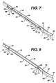
- FIG. 7 is a perspective view of a portion of the main shaft and slide rod of the instrument of FIGS. 1-6 , with part of the main shaft removed for purposes of illustration and showing the instrument in the open or unclamped position;
- FIG. 8 is a perspective view of a portion of the main shaft and slide rod of the instrument of FIGS. 1-6 , with part of the main shaft removed for purposes of illustration and showing the instrument in the closed or clamped position;
- FIG. 9 is a top plan view of the slide rod of the instrument of FIGS. 1-8 ;
- FIG. 10 is a side elevation of the slide rod of FIG. 9 ;
- FIG. 11 is a top plan view of the main shaft of the instrument of FIGS. 1-8 ;
- FIG. 12 is a side elevation of the main shaft of FIG. 11 ;
- FIG. 13 is a top plan view of the distal end of the instrument of FIGS. 1-8 showing an orthopaedic implant held between the main shaft and the slide rod;
- FIG. 14 is a transverse cross-section of the main shaft of the instrument of FIGS. 1-8 , taken along line 14 - 14 of FIG. 11 ;
- FIG. 15 is a transverse cross-section of the main shaft of the instrument of FIGS. 1-8 , taken along line 15 - 15 of FIG. 12 ;
- FIG. 16 is an enlarged side view or elevation of one of the extensions of the slide rod of FIGS. 9-10 ;
- FIG. 17 is a transverse cross-section of the slide rod assembled on the main shaft, taken along line 17 - 17 of FIG. 6 ;
- FIG. 18 is a perspective view of the instrument of FIGS. 1-6 , shown in the closed or clamped position with an implant clamped at the distal end of the instrument, and shown in combination with an implant protector, the implant protector being shown in longitudinal cross-section;
- FIG. 19 is a perspective view of the implant protector of FIG. 18 ;
- FIG. 20 is a perspective view of an alternate implant protector
- FIG. 21 is a side elevation of the instrument of FIGS. 1-6 shown in combination with an alternate implant protector
- FIG. 22 is the opposite side elevation of the combination instrument and implant protector of FIG. 21 ;
- FIG. 23 is an end view of the implant protector of FIGS. 21-22 ;
- FIG. 24 is a side elevation or view of a second instrument illustrating the principles of the present invention, the instrument being shown in an open or unclamped position;
- FIG. 25 is a perspective view of the instrument of FIG. 24 , with parts of the handle removed;
- FIG. 26 is a perspective view of the instrument of FIG. 24 , similar to FIG. 25 but with the instrument in the closed or clamped position;
- FIG. 27 is a perspective view of the instrument of FIG. 24 , similar to FIG. 26 but with parts of the instrument shown in cross-section;
- FIG. 28 is a side elevation of the distal end of the slide arm of the instrument of FIG. 24 ;
- FIG. 29 is a side elevation of the distal end of the instrument of FIG. 24 shown in the open or unclamped position;
- FIG. 30 is a perspective view of the distal end of the instrument of FIG. 24 shown in the closed or clamped position;
- FIG. 31 is a perspective view of the distal end of the instrument of FIG. 24 similar to FIG. 29 but shown with an implant;
- FIG. 32 is a side elevation of the distal end of the instrument of FIG. 24 , similar to FIG. 30 but shown with an implant;
- FIG. 33 is a side elevation of an alternative distal end for a surgical instrument shown in the closed position
- FIG. 34 is a side elevation of the alternative distal end for the surgical instrument shown in FIG. 33 but shown in the open position;
- FIG. 35 is a side elevation for an alternative distal end for the surgical instrument of FIGS. 24-32 , shown in the open or unclamped position;
- FIG. 36 is a side elevation similar to FIG. 35 but shown with the instrument in the closed or clamped position;
- FIG. 37 is a perspective view of the alternative distal end of FIG. 35 but shown with an implant.
- FIG. 38 is a perspective view of the alternative distal end of FIG. 36 but shown with an implant.
- the instrument of the present invention is useful in delivering an orthopaedic implant, as defined above, to a damaged joint site in the body.
- the damaged joint site may for example be an intra-articular site such as the knee, where the instrument can be used to deliver an orthopaedic implant for use in approximating, repairing or regenerating a diseased or damaged meniscus.
- the damaged intra-articular site may be in other locations in the body, such as the temporomandibular joint, between vertebrae, or any site where there is fibrocartilage in need of approximation, repair or regeneration.
- the instrument of the present invention can also be used to deliver an orthopaedic implant to location outside of the intra-articular space of a joint site.
- the instrument of the present invention can be used to deliver an orthopaedic implant to a damaged joint site such as the area of the rotator cuff of the shoulder joint site.
- joint site as used herein is intended to include the intra-articular space and other areas near the bones comprising a joint.
- the instrument of the present invention may also find utility in delivering an implant to damaged tissue sites other than the joints.
- “Damaged tissue site”, unless expressly limited in the claims, is intended to mean a tissue site that requires surgical repair, whether due to injury, degeneration or disease.
- the first embodiment of the instrument is illustrated in FIGS. 1-18 and 21 - 22 .
- the first illustrated instrument 10 includes a handle 12 at the proximal end 14 , a main shaft 16 and a slide rod 18 .
- the main shaft 16 and slide rod 18 extend from the handle 12 to the distal end 19 of the instrument 10 .
- the first illustrated instrument 10 may also optionally include a delivery guide 20 , shown in FIGS. 1 , 3 , 21 and 22 but not in FIGS. 2 , 4 and 5 - 20 .
- the handle 12 of the first illustrated instrument 10 includes two arms 22 , 24 connected together at a pivot 26 .
- Each arm 22 , 24 includes a grip portion 28 , 30 through which the surgeon may insert a thumb and a finger and squeeze to pivot the arms about pivot 26 .
- the grip portions 28 , 30 are brought closer together, the slide arm 18 is moved from the open or unclamped position shown in FIGS. 1-2 , 5 and 7 to the closed or clamped position shown in FIGS. 3-4 , 6 and 8 .
- FIGS. 1 and 3 also illustrate a possible locking mechanism 32 that cooperates with the arms 22 , 24 for locking the slide arm 18 in either the open or closed positions.
- One arm 22 has a body portion 23 that is connected to a proximal end 34 of the main shaft 16 of the instrument 10 through standard means, such as a set screw or the like.
- the body portion 23 of the arm 22 is opposite the grip portion 28 and has an opening and channel (not shown) extending in a proximal-distal direction to receive the proximal end portion 34 of the main shaft 16 .
- the proximal end portion 34 of the main shaft 16 may have indentations or cavities 36 , 38 that align with holes (not shown) in the body portion 23 of the arm 22 so that screws or the like can be used to secure the main shaft 16 to the body 23 of the arm 22 .
- other means of connecting the main shaft 16 to the arm 22 may be used, and that the main shaft 16 and arm 22 could be made integral if desired.
- the other arm 24 has a top end 40 opposite its grip portion 30 .
- the pivot 26 that connects the two arms 22 , 24 is positioned between the top end 40 and grip portion 30 .
- the top portion 40 of the arm 24 is pivoted in a generally proximal direction.
- the grip portions 28 , 30 are released, the top end 40 of the arm 24 is pivoted in a generally distal direction.
- the top end 40 of the arm 24 has a hole or slot 42 (see FIGS. 5-6 ) that receives the proximal end 44 of the slide rod 18 .
- a pin 45 or other suitable mechanical connector is used to connect the slide rod 18 to the top end 40 of the arm; this pin may provide a pivotable connection.
- the proximal end 44 of the slide rod 18 has a hole 46 to receive the pin 45 .
- a portion of the slide rod 18 at its proximal end 44 has a reduced height or thickness; this portion, designated 47 in FIG. 10 , extends through the channel (not shown) in the body 23 of arm 22 .
- the slide rod 18 is also moved in a distal direction; when the top end 40 of the arm 24 is moved in a proximal direction, the side rod 18 is also moved in a proximal direction.
- the slide rod 18 has a thin elongate portion 48 extending from its proximal end 44 to a thicker curved portion 50 at its distal end 52 .
- the slide rod also has a pair of spaced, integral downward-extending extensions 54 , 56 .
- Each extension 54 , 56 has a distal edge or surface 58 , 60 defining an obtuse angle with the bottom edge or surface 62 of the adjacent segments of the thin elongate portion 48 .
- the distal edges 58 , 60 are parallel to each other.
- Each extension 54 , 56 also has a through slot 64 , 66 (see FIGS. 7-8 and 10 ).
- the through slots 64 , 66 of both extensions 54 , 56 are parallel to each other and extend upward in a distal direction. As shown in FIGS. 7-8 , the through slots 64 , 66 each receive a pin 68 , 70 .
- a substantial part of the thin elongate portion 48 of the slide rod 18 is received in an elongate channel 72 of the main shaft 16 .
- the channel 72 is defined by two spaced parallel side walls 74 , 76 and a bottom wall 78 .
- the channel 72 extends from the junction of the main shaft 16 with the body 23 of the arm 22 to a thick curved portion 80 at the distal end 82 of the main shaft 16 .
- the curved portion 80 of the main shaft 16 is displaced downward from the bottom edge or surface 84 of the bottom wall 78 .
- the side walls 74 , 76 of the main shaft 16 have spaced, aligned through holes 86 , 87 , 88 , 89 .
- These through holes 86 , 87 , 88 , 89 receive pins 68 , 70 to mount the slide rod 18 to the main shaft 16 .
- the bottom wall 78 has a pair of slots 90 , 91 positioned near the through holes 86 , 87 , 88 , 89 .
- the extensions 54 , 56 of the slide rod 18 are received in these slots 90 , 91 .
- the curved portions 50 , 80 of the main shaft 16 and slide rod 18 are similarly shaped. Each has a radius of about 1.1 inches.
- the curved portion 50 of the slide rod has a length of 0.773 inches and the curved portion 80 of the main shaft 16 has a length of 0.783 inches. It should be understood that these dimensions are provided as examples only; the present invention is not limited to any particular dimension unless expressly set forth in the claims.
- the grips 28 , 30 are moved apart to place the instrument in the open or unclamped position shown in FIGS. 1-2 , 5 and 7 .
- the distal end 52 of the slide rod 18 extends distally beyond the distal end 82 of the main shaft 16 .
- the curved portions 50 , 80 of the slide rod 18 and main shaft 16 are spaced apart by a gap 92 of about 1-2 mm.
- the total height of the distal end of the instrument, including the heights of the gap 92 (at the fully open or unclamped position) and the heights of the curved portions 50 , 80 is about 5 mm.
- a meniscal implant shown at 94 may comprise a flat periphery 96 and an inner wedge-shaped portion 98 with curved inner and outer edges 100 , 102 .
- Such a meniscal implant 94 may be used to replace a part of a damaged meniscus removed in a menisectomy.
- the curvature of the spaced curved portions 50 , 80 of the slide rod 18 and main shaft 16 follows the curvature of the inner edge 100 of the wedge-shaped portion 98 of the implant.
- the curvature of the spaced portions 50 , 80 of the slide rod and main shaft protect the inner edge 100 of the wedge-shaped portion 98 of the implant as it is introduced to the damaged tissue site.
- the flat periphery 96 of the implant 94 is inserted in the gap 92 between the curved portions 50 , 80 of the main shaft 16 and slide rod 18 .
- the curved inner edge 100 of the inner wedge-shaped portion 98 of the implant is placed along side the curved edges of the portions 50 , 80 of the main shaft and slide rod.
- the surgeon may close the instrument to clamp the implant between the curved portions 50 , 80 of the main shaft 16 and slide rod 18 .
- the surgeon moves the grip portions 28 , 30 of the arms 22 , 24 closer together, causing the top end 40 of the arm 24 to pivot away from the body 23 of the arm 22 .
- the slide rod 18 is pulled in a proximal direction.
- the slide rod 18 moves proximally, it also moves deeper into the channel 72 as the slots 64 , 66 of the extensions 54 , 56 move downward along the pins 68 , 70 until the pins 68 , 70 are at or near the top ends of the slots 64 , 66 .
- the extensions 54 , 56 move deeper into the slots 90 , 91 of the main shaft 16
- the curved portion 50 of the slide rod 18 moves closer to the curved portion of the main shaft 80 .
- the gap 92 is closed, clamping the periphery 96 of the implant 94 between the two curved portions 50 , 80 .
- the total height of the distal end of the instrument decreases.
- the surgeon may then deliver the implant 94 to the damaged tissue site. If the surgery is an arthroscopic procedure, or a mini-arthrotomy, access to the damaged tissue site may be confined. To prevent the implant 94 from being damaged by the close confines of the damaged tissue site, the surgeon may use the first illustrated instrument in combination with an implant protector.
- implant protector that may be used is an elongate tube as illustrated in FIGS. 18-19 .
- the implant protector 104 comprises a hollow, open-ended tube that is oval-shaped in cross-section.
- the implant protector 104 has a slot 106 extending along its length. In the illustrated embodiment, the slot 106 is along the top of the tube.
- the surgeon may place the distal end 108 of the implant protector at the damaged tissue site, such as in the intra-articular space of the knee near the area where a portion of the meniscus has been removed.
- the implant protector 104 is long enough so that its proximal end 110 is exposed outside of the patient's body.
- the surgeon may insert the distal end 19 of the instrument 10 , with the implant 94 captured by the curved portions 50 , 80 , into the implant protector 104 and move the distal end 19 of the instrument 10 in a distal direction along the length of the implant protector 104 until the distal end 19 of the instrument 10 and the implant 94 are at the damaged tissue site beyond the distal end 108 of the implant protector 104 .
- the surgeon may then release the implant 94 from the instrument 10 .
- the grip portions 28 , 30 of the arms 22 , 24 are moved apart.
- the slide rod 18 is moved in a distal direction.
- the extensions 54 , 56 move upwardly and distally along the pins 68 , 70 and the entire slide rod 18 moves upward in the channel 72 .
- the curved portion 50 of the slide rod separates from the curved portion 80 of the main shaft 16 , releasing the implant 94 .
- the released implant may then be moved into its final position and secured to native tissue.
- the surgeon may also use the device disclosed in U.S. patent application Ser. No. 10/609,768 entitled “Implant Stabilizing Instrument, Kit and Method,” filed concurrently herewith by Andrew M. Jacobs, Carolyn K. Day, Rhonda B. Clarke, Herbert E. Schwartz, John W. Kemppainen, Prasanna Malaviya and Anthony D. Zannis, which is incorporated by reference herein in its entirety.
- the instrument, kit and method disclosed in that patent application may be used to move and stabilize the implant while securing the implant to the native tissue.
- the instrument 10 requires little space when in the open or unclamped position. This feature of the invention is particularly advantageous when delivering an implant to a damaged tissue site that is closely confined, such as in the intra-articular space of a joint.
- the instrument may be pulled in a proximal direction until its distal end 19 is free from the implant protector 104 outside of the patient's body.
- the surgeon may raise the instrument so that the main shaft 16 and slide rod 18 are raised through the slot 106 of the implant protector 104 . Once the main shaft 16 and slide rod 18 are clear of the implant protector 104 , the instrument may be moved out of the patient's body.
- an implant protector 112 can comprise an elongate hollow, open-ended tube of circular cross-section. If desired, the implant protector 112 can have a slot as in the first illustrated implant protector 104 .
- FIGS. 21-23 Another implant protector 114 is illustrated in FIGS. 21-23 .
- This implant protector 114 is used in conjunction with the delivery guide 20 illustrated mounted on the instrument 10 in FIGS. 1 , 3 , 21 and 22 .
- This implant protector 114 comprises an elongate guide shaft 116 and an integral protector 118 at its distal end 120 .
- a portion of the guide shaft 116 is received in a complementary channel on the top of the delivery guide 20 to mount the implant protector 114 to the instrument 10 .
- the integral protector 118 is sized and shaped to substantially surround the curved portions 50 , 80 of the instrument and an implant fixed between these curved portions 50 , 80 .
- All of the implant protectors may be sized to fit through a standard arthroscopic portal. Typical arthroscopic portals have a length of about 8-12 mm. However, the surgical instrument 10 and implant protectors may also be used in a minimally invasive procedure, such as a mini-arthrotomy, as well as in an open arthrotomy or other orthopaedic surgical procedure. The instruments and protectors could have larger sizes for use in these other procedures. In addition, it should be understood that the present invention is not limited to any particular dimension unless expressly called for in the claims.
- the structure of the first illustrated instrument 10 can be modified if desired.
- parts shown as assembled may be made integral and parts shown as a single element may be constructed as assemblies.
- the end portions of the main shaft 16 and the slide rod 18 can be shaped to correspond with the shape of the implant if the implant is different from that shown in the drawings; for example, the distal ends 52 , 82 of the main shaft 16 and slide rod 18 could be straight.
- the end portions of the main shaft and slide rod protect the inner edge of the implant from potential damage as the implant is introduced to the damaged tissue site.
- FIGS. 24-32 Another embodiment of a surgical instrument illustrating the principles of the present invention is illustrated in FIGS. 24-32 .
- the second illustrated instrument 210 includes a handle 212 at the proximal end 214 , a main shaft 216 and a slide arm 218 .
- the main shaft 216 and slide arm 218 extend from the handle 212 to the distal end 219 of the instrument 210 .
- the handle 212 of the second illustrated instrument 210 includes two arms 222 , 224 connected together at a pivot 226 .
- Each arm 222 , 224 includes a grip portion 228 , 230 that the surgeon squeeze to pivot the arms about pivot 226 .
- the slide arm 218 is moved from an open or unclamped position, shown in FIGS. 24-25 , 29 and 31 , to a closed or clamped position, shown in FIGS. 26-27 , 30 and 32 .
- One arm 224 is integral with the main shaft 216 of the instrument 210 .
- the other arm 222 is integral with the slide arm 218 of the instrument 210 .
- the grip portions 228 , 230 of the arms 222 , 224 are squeezed together, the top portion of the arm 222 and the integral slide arm 218 are moved in a generally distal direction.
- a spring mechanism 232 urges the arms 222 , 224 and the integral main shaft 216 and slide arm 218 to the open or unclamped position shown in FIGS. 24 and 25 .
- the slide arm 218 of the second illustrated instrument 210 has a distal end 252 illustrated in side elevation in FIG. 28 . As there shown, the distal end 252 is tapered in side elevation. The height of the distal end 252 of the slide arm 218 gradually increases in the proximal direction. The top surface 235 of the distal end 252 of the slide arm 218 defines an angle ⁇ with the bottom surface 237 of the distal end 252 of the slide arm 218 .
- the main shaft 216 of the second illustrated instrument 210 has a distal end 282 that is smoothly curved, or bull-nosed in shape.
- the distal end 282 is shaped to define an enlarged well 283 that may receive part of an implant.
- the well 283 is open at its top facing the bottom surface 237 of the slide arm 218 .
- the well 283 may be sized and shaped so that a substantial part of the implant is received within the well 283 .
- the minimum vertical distance between the bottom surface 237 of the slide arm 218 and the top surface 285 of the main shaft 216 surrounding the well 283 is shown in FIG. 29 at d 1 .
- distance d 1 is greater than the thickness of the implant.
- a substantial part of the well 283 is exposed or uncovered when the instrument 210 is in the open or unclamped position.
- the minimum vertical distance between the bottom surface 237 of the slide arm 218 and the top surface 285 of the main shaft 216 surrounding the well 283 decreases substantially to the distance shown at d 2 in FIG. 30 .
- distance d 2 is equal to or slightly less than the thickness of the implant. Also as shown in FIGS. 26-27 and 30 , when a substantial part of the well 283 is covered by the distal end 252 of the slide arm 218 when the instrument 210 is in the closed or clamped position.
- the implant 294 rests loosely on and in the well 283 at the distal end 282 of the main shaft 216 and the implant is substantially uncovered.
- the instrument 210 is in the closed or clamped position a shown in FIG. 32 , part of the implant 294 is secured or squeezed between the bottom surface 237 of the slide arm 218 and the top surface 285 of the main shaft 216 and the implant is substantially covered by the distal end of the slide arm 218 . Only a small part of the periphery of the implant 294 is exposed.
- the implant 294 will be substantially protected from damage as it is introduced to the damaged tissue site.
- the surgeon can use standard surgical procedures to introduce the implant using the second illustrated instrument 210 , and may use the technique described above using implant protectors like those shown in FIGS. 19 and 20 .
- it may not be necessary to use separate implant protectors like those shown in FIGS. 19 and 20 since the distal end of the instrument 210 substantially encloses the implant to protect the implant from damage.
- the bull-nose distal end of the second instrument 210 may be smooth and rounded to prevent cutting or abrasion of native tissue as the bull-nose distal end is moved through native tissue to deliver the implant.
- FIGS. 35-38 An alternative distal end for the instrument of FIGS. 24-32 is shown in FIGS. 35-38 .
- the distal end of the main shaft could be open instead of bull-nosed as in the embodiment illustrated in FIGS. 24-32 .
- the distal surfaces of the distal end of the main shaft may be finished to be smooth with no sharp edges to damage tissue as the instrument is introduced to the damaged tissue site.
- FIGS. 35-38 the same reference numbers have been used as in FIGS. 24-32 , followed by the letter “a” to indicate that FIGS. 35-38 is an alternative embodiment.
- the remaining features of the instrument of FIGS. 35-38 may be like those described above for the instrument of FIGS. 24-32 .
- the distal end 52 , 252 of the slide rod or arm 18 , 218 is displaced in the proximal-distal direction as the instrument is moved between the open and closed position.
- the gap between the distal end 52 , 252 of the slide rod or arm 18 , 218 and the distal end 82 , 282 of the main shaft 16 , 216 decreases as the instrument is closed or clamped.
- the distal end of the slide rod or arm moves between the open and closed positions without pivoting.
- the maximum distance between the top surface of the distal end of the slide rod or arm and the bottom surface of the distal end of the main shaft can be made to be less than 12 mm so that the instrument can be used in arthroscopic surgery and so that the instrument can be opened to release the implant in a confined space, such as that present in a typical intra-articular site.
- a main shaft 316 could be provided with a distal end 382 shaped like that of the second instrument 210 , with a bull-nosed end and an enlarged well 383 .
- the top member could comprise a pivotable cover 318 at the distal end 352 , connected to one of the arms (not shown) through an actuator cable 353 and to the main shaft 316 through a hinge pin 317 .
- the implant 33-34 should be suitable to protect the implant from damage as the implant is delivered to the damaged tissue site, since a substantial part of the implant can be received in the well 383 and since the implant will be substantially covered by the pivotable cover 318 .
- the distal surfaces of the main shaft 316 and pivotable cover 318 can be curved and smooth to prevent damage to native tissue as the implant is delivered.
- All of the above illustrated instruments 10 , 210 can be made of standard materials for surgical instruments.
- the implant protectors 104 , 112 can also be made of standard materials, including surgical grade plastic such as ABS plastic.
- the present invention is expected to have particular utility in delivering orthopaedic implants to damaged joint sites, although it will be appreciated that the invention has broader applications.
- the instrument of the present invention can also be used to deliver other types of implants to other damaged tissue sites in the body.
- the present invention could be used to deliver any type of tissue scaffold, patch, or graft (allograft, autograft or heterograft) to any type of tissue, and the illustrated embodiments may be modified if desired to allow for such use.
- the claims should not be construed as being limited to the delivery of orthopaedic implants to damaged joint sites.
Abstract
Description
Claims (6)
Priority Applications (1)
| Application Number | Priority Date | Filing Date | Title |
|---|---|---|---|
| US10/742,020 US7559941B2 (en) | 2003-06-30 | 2003-12-19 | Instrument for delivery of implant |
Applications Claiming Priority (2)
| Application Number | Priority Date | Filing Date | Title |
|---|---|---|---|
| US48380403P | 2003-06-30 | 2003-06-30 | |
| US10/742,020 US7559941B2 (en) | 2003-06-30 | 2003-12-19 | Instrument for delivery of implant |
Publications (2)
| Publication Number | Publication Date |
|---|---|
| US20040267304A1 US20040267304A1 (en) | 2004-12-30 |
| US7559941B2 true US7559941B2 (en) | 2009-07-14 |
Family
ID=33544704
Family Applications (1)
| Application Number | Title | Priority Date | Filing Date |
|---|---|---|---|
| US10/742,020 Active 2026-08-19 US7559941B2 (en) | 2003-06-30 | 2003-12-19 | Instrument for delivery of implant |
Country Status (1)
| Country | Link |
|---|---|
| US (1) | US7559941B2 (en) |
Cited By (53)
| Publication number | Priority date | Publication date | Assignee | Title |
|---|---|---|---|---|
| US20040267277A1 (en) * | 2003-06-30 | 2004-12-30 | Zannis Anthony D. | Implant delivery instrument |
| US20080154302A1 (en) * | 2002-03-15 | 2008-06-26 | Nmt Medical, Inc. | Coupling system useful in the placement of implants |
| US20110004221A1 (en) * | 2009-06-04 | 2011-01-06 | Euteneuer Charles L | Methods and apparatus for deploying sheet-like materials |
| US20110224702A1 (en) * | 2010-03-11 | 2011-09-15 | Craig Van Kampen | Tendon repair implant and method of arthroscopic implantation |
| US8110005B2 (en) | 2000-04-10 | 2012-02-07 | Biomet Manufacturing Corp. | Modular prosthesis and use thereof for replacing a radial head |
| CN103230298A (en) * | 2013-05-15 | 2013-08-07 | 向川 | Arc-shaped sawtooth shear type meniscus trimmer |
| US8535382B2 (en) | 2000-04-10 | 2013-09-17 | Biomet Manufacturing, Llc | Modular radial head prostheses |
| US8668718B2 (en) | 2009-06-04 | 2014-03-11 | Rotation Medical, Inc. | Methods and apparatus for fixing sheet-like materials to a target tissue |
| US8864780B2 (en) | 2011-02-15 | 2014-10-21 | Rotation Medical, Inc. | Methods and apparatus for delivering and positioning sheet-like materials |
| US8920509B2 (en) | 2000-04-10 | 2014-12-30 | Biomet Manufacturing, Llc | Modular radial head prosthesis |
| US8961551B2 (en) | 2006-12-22 | 2015-02-24 | The Spectranetics Corporation | Retractable separating systems and methods |
| US9028520B2 (en) | 2006-12-22 | 2015-05-12 | The Spectranetics Corporation | Tissue separating systems and methods |
| US9033201B2 (en) | 2011-02-15 | 2015-05-19 | Rotation Medical, Inc. | Methods and apparatus for fixing sheet-like materials to a target tissue |
| US9101460B2 (en) | 2009-01-08 | 2015-08-11 | Rotation Medical, Inc. | Implantable tendon protection systems and related kits and methods |
| US9107661B2 (en) | 2011-12-19 | 2015-08-18 | Rotation Medical, Inc. | Fasteners and fastener delivery devices for affixing sheet-like materials to bone or tissue |
| US9113954B2 (en) | 2004-10-29 | 2015-08-25 | DePuy Synthes Products, Inc. | Coordinate instrument set |
| US9113977B2 (en) | 2011-02-15 | 2015-08-25 | Rotation Medical, Inc. | Guidewire having a distal fixation member for delivering and positioning sheet-like materials in surgery |
| US9125650B2 (en) | 2011-12-19 | 2015-09-08 | Rotation Medical, Inc. | Apparatus and method for forming pilot holes in bone and delivering fasteners therein for retaining an implant |
| US9179910B2 (en) | 2009-03-20 | 2015-11-10 | Rotation Medical, Inc. | Medical device delivery system and method |
| US9198751B2 (en) | 2011-02-15 | 2015-12-01 | Rotation Medical, Inc. | Methods and apparatus for delivering and positioning sheet-like materials in surgery |
| US9204940B2 (en) | 2011-02-15 | 2015-12-08 | Rotation Medical, Inc. | Anatomical location markers and methods of use in positioning sheet-like materials during surgery |
| US9271726B2 (en) | 2011-12-19 | 2016-03-01 | Rotation Medical, Inc. | Fasteners and fastener delivery devices for affixing sheet-like materials to bone or tissue |
| US9283040B2 (en) | 2013-03-13 | 2016-03-15 | The Spectranetics Corporation | Device and method of ablative cutting with helical tip |
| US9291663B2 (en) | 2013-03-13 | 2016-03-22 | The Spectranetics Corporation | Alarm for lead insulation abnormality |
| US9370356B2 (en) | 2011-12-19 | 2016-06-21 | Rotation Medical, Inc. | Fasteners and fastener delivery devices for affixing sheet-like materials to bone or tissue |
| US9413896B2 (en) | 2012-09-14 | 2016-08-09 | The Spectranetics Corporation | Tissue slitting methods and systems |
| USD765243S1 (en) | 2015-02-20 | 2016-08-30 | The Spectranetics Corporation | Medical device handle |
| US9456872B2 (en) | 2013-03-13 | 2016-10-04 | The Spectranetics Corporation | Laser ablation catheter |
| USD770616S1 (en) | 2015-02-20 | 2016-11-01 | The Spectranetics Corporation | Medical device handle |
| US9603618B2 (en) | 2013-03-15 | 2017-03-28 | The Spectranetics Corporation | Medical device for removing an implanted object |
| US9668765B2 (en) | 2013-03-15 | 2017-06-06 | The Spectranetics Corporation | Retractable blade for lead removal device |
| US9883885B2 (en) | 2013-03-13 | 2018-02-06 | The Spectranetics Corporation | System and method of ablative cutting and pulsed vacuum aspiration |
| US9925366B2 (en) | 2013-03-15 | 2018-03-27 | The Spectranetics Corporation | Surgical instrument for removing an implanted object |
| US9980743B2 (en) | 2013-03-15 | 2018-05-29 | The Spectranetics Corporation | Medical device for removing an implanted object using laser cut hypotubes |
| US10123796B2 (en) | 2014-11-04 | 2018-11-13 | Rotation Medical, Inc. | Medical implant delivery system and related methods |
| US10136913B2 (en) | 2013-03-15 | 2018-11-27 | The Spectranetics Corporation | Multiple configuration surgical cutting device |
| US10258459B2 (en) | 2014-05-09 | 2019-04-16 | Rotation Medical, Inc. | Medical implant delivery system and related methods |
| US10265156B2 (en) | 2015-06-15 | 2019-04-23 | Rotation Medical, Inc | Tendon repair implant and method of implantation |
| US10314689B2 (en) | 2015-12-31 | 2019-06-11 | Rotation Medical, Inc. | Medical implant delivery system and related methods |
| US10383691B2 (en) | 2013-03-13 | 2019-08-20 | The Spectranetics Corporation | Last catheter with helical internal lumen |
| US10405924B2 (en) | 2014-05-30 | 2019-09-10 | The Spectranetics Corporation | System and method of ablative cutting and vacuum aspiration through primary orifice and auxiliary side port |
| US10448999B2 (en) | 2013-03-15 | 2019-10-22 | The Spectranetics Corporation | Surgical instrument for removing an implanted object |
| US10758228B2 (en) | 2015-11-03 | 2020-09-01 | Rotation Medical, Inc. | Fastener delivery system and related methods |
| US10835368B2 (en) | 2017-12-07 | 2020-11-17 | Rotation Medical, Inc. | Medical implant delivery system and related methods |
| US10835279B2 (en) | 2013-03-14 | 2020-11-17 | Spectranetics Llc | Distal end supported tissue slitting apparatus |
| US10842532B2 (en) | 2013-03-15 | 2020-11-24 | Spectranetics Llc | Medical device for removing an implanted object |
| US10898228B2 (en) | 2015-05-06 | 2021-01-26 | Rotation Medical, Inc. | Medical implant delivery system and related methods |
| US11076851B2 (en) | 2014-11-04 | 2021-08-03 | Rotation Medical, Inc. | Medical implant delivery system and related methods |
| US11259939B2 (en) | 2020-02-11 | 2022-03-01 | Embody, Inc. | Implant delivery device |
| US11413032B2 (en) | 2020-02-11 | 2022-08-16 | Embody, Inc. | Surgical anchoring device, deployment device, and method of use |
| US11457916B2 (en) | 2014-11-04 | 2022-10-04 | Rotation Medical, Inc. | Medical implant delivery system and related methods |
| US11559330B2 (en) | 2020-02-11 | 2023-01-24 | Embody, Inc. | Surgical cannula with removable pressure seal |
| US11779371B1 (en) | 2022-10-28 | 2023-10-10 | Expand Medical Ltd. | Implant delivery device |
Families Citing this family (90)
| Publication number | Priority date | Publication date | Assignee | Title |
|---|---|---|---|---|
| US7608092B1 (en) | 2004-02-20 | 2009-10-27 | Biomet Sports Medicince, LLC | Method and apparatus for performing meniscus repair |
| US7857851B2 (en) * | 2004-10-29 | 2010-12-28 | Depuy Products, Inc. | Implant system with sizing templates |
| US7785332B2 (en) * | 2004-10-29 | 2010-08-31 | Depuy Products, Inc. | Method of delivering therapeutic implant |
| US7749250B2 (en) | 2006-02-03 | 2010-07-06 | Biomet Sports Medicine, Llc | Soft tissue repair assembly and associated method |
| US8298262B2 (en) | 2006-02-03 | 2012-10-30 | Biomet Sports Medicine, Llc | Method for tissue fixation |
| US8303604B2 (en) | 2004-11-05 | 2012-11-06 | Biomet Sports Medicine, Llc | Soft tissue repair device and method |
| US7857830B2 (en) | 2006-02-03 | 2010-12-28 | Biomet Sports Medicine, Llc | Soft tissue repair and conduit device |
| US8137382B2 (en) | 2004-11-05 | 2012-03-20 | Biomet Sports Medicine, Llc | Method and apparatus for coupling anatomical features |
| US8118836B2 (en) | 2004-11-05 | 2012-02-21 | Biomet Sports Medicine, Llc | Method and apparatus for coupling soft tissue to a bone |
| US8128658B2 (en) | 2004-11-05 | 2012-03-06 | Biomet Sports Medicine, Llc | Method and apparatus for coupling soft tissue to bone |
| US7905904B2 (en) | 2006-02-03 | 2011-03-15 | Biomet Sports Medicine, Llc | Soft tissue repair device and associated methods |
| US7658751B2 (en) | 2006-09-29 | 2010-02-09 | Biomet Sports Medicine, Llc | Method for implanting soft tissue |
| US8088130B2 (en) | 2006-02-03 | 2012-01-03 | Biomet Sports Medicine, Llc | Method and apparatus for coupling soft tissue to a bone |
| US8361113B2 (en) | 2006-02-03 | 2013-01-29 | Biomet Sports Medicine, Llc | Method and apparatus for coupling soft tissue to a bone |
| US9801708B2 (en) | 2004-11-05 | 2017-10-31 | Biomet Sports Medicine, Llc | Method and apparatus for coupling soft tissue to a bone |
| US8840645B2 (en) | 2004-11-05 | 2014-09-23 | Biomet Sports Medicine, Llc | Method and apparatus for coupling soft tissue to a bone |
| US20060189993A1 (en) | 2004-11-09 | 2006-08-24 | Arthrotek, Inc. | Soft tissue conduit device |
| US9017381B2 (en) | 2007-04-10 | 2015-04-28 | Biomet Sports Medicine, Llc | Adjustable knotless loops |
| US7909851B2 (en) | 2006-02-03 | 2011-03-22 | Biomet Sports Medicine, Llc | Soft tissue repair device and associated methods |
| US7905903B2 (en) | 2006-02-03 | 2011-03-15 | Biomet Sports Medicine, Llc | Method for tissue fixation |
| US7914539B2 (en) | 2004-11-09 | 2011-03-29 | Biomet Sports Medicine, Llc | Tissue fixation device |
| US8998949B2 (en) | 2004-11-09 | 2015-04-07 | Biomet Sports Medicine, Llc | Soft tissue conduit device |
| US8034090B2 (en) | 2004-11-09 | 2011-10-11 | Biomet Sports Medicine, Llc | Tissue fixation device |
| US9538998B2 (en) | 2006-02-03 | 2017-01-10 | Biomet Sports Medicine, Llc | Method and apparatus for fracture fixation |
| US8574235B2 (en) | 2006-02-03 | 2013-11-05 | Biomet Sports Medicine, Llc | Method for trochanteric reattachment |
| US9149267B2 (en) | 2006-02-03 | 2015-10-06 | Biomet Sports Medicine, Llc | Method and apparatus for coupling soft tissue to a bone |
| US9271713B2 (en) | 2006-02-03 | 2016-03-01 | Biomet Sports Medicine, Llc | Method and apparatus for tensioning a suture |
| US8968364B2 (en) | 2006-02-03 | 2015-03-03 | Biomet Sports Medicine, Llc | Method and apparatus for fixation of an ACL graft |
| US11311287B2 (en) | 2006-02-03 | 2022-04-26 | Biomet Sports Medicine, Llc | Method for tissue fixation |
| US8652172B2 (en) | 2006-02-03 | 2014-02-18 | Biomet Sports Medicine, Llc | Flexible anchors for tissue fixation |
| US9468433B2 (en) | 2006-02-03 | 2016-10-18 | Biomet Sports Medicine, Llc | Method and apparatus for forming a self-locking adjustable loop |
| US8771352B2 (en) | 2011-05-17 | 2014-07-08 | Biomet Sports Medicine, Llc | Method and apparatus for tibial fixation of an ACL graft |
| US7959650B2 (en) | 2006-09-29 | 2011-06-14 | Biomet Sports Medicine, Llc | Adjustable knotless loops |
| US8506597B2 (en) | 2011-10-25 | 2013-08-13 | Biomet Sports Medicine, Llc | Method and apparatus for interosseous membrane reconstruction |
| US8562645B2 (en) | 2006-09-29 | 2013-10-22 | Biomet Sports Medicine, Llc | Method and apparatus for forming a self-locking adjustable loop |
| US8801783B2 (en) | 2006-09-29 | 2014-08-12 | Biomet Sports Medicine, Llc | Prosthetic ligament system for knee joint |
| US11259792B2 (en) | 2006-02-03 | 2022-03-01 | Biomet Sports Medicine, Llc | Method and apparatus for coupling anatomical features |
| US8597327B2 (en) | 2006-02-03 | 2013-12-03 | Biomet Manufacturing, Llc | Method and apparatus for sternal closure |
| US8251998B2 (en) | 2006-08-16 | 2012-08-28 | Biomet Sports Medicine, Llc | Chondral defect repair |
| US8652171B2 (en) | 2006-02-03 | 2014-02-18 | Biomet Sports Medicine, Llc | Method and apparatus for soft tissue fixation |
| US9078644B2 (en) | 2006-09-29 | 2015-07-14 | Biomet Sports Medicine, Llc | Fracture fixation device |
| US8562647B2 (en) | 2006-09-29 | 2013-10-22 | Biomet Sports Medicine, Llc | Method and apparatus for securing soft tissue to bone |
| US10517587B2 (en) | 2006-02-03 | 2019-12-31 | Biomet Sports Medicine, Llc | Method and apparatus for forming a self-locking adjustable loop |
| JP4869736B2 (en) * | 2006-03-01 | 2012-02-08 | オリンパス株式会社 | Cell sheet mounting method and mounting device |
| US20080027544A1 (en) * | 2006-07-28 | 2008-01-31 | Warsaw Orthopedic Inc. | Instruments and techniques for engaging spinal implants for insertion into a spinal space |
| US9918826B2 (en) | 2006-09-29 | 2018-03-20 | Biomet Sports Medicine, Llc | Scaffold for spring ligament repair |
| US11259794B2 (en) | 2006-09-29 | 2022-03-01 | Biomet Sports Medicine, Llc | Method for implanting soft tissue |
| US8500818B2 (en) | 2006-09-29 | 2013-08-06 | Biomet Manufacturing, Llc | Knee prosthesis assembly with ligament link |
| US8672969B2 (en) | 2006-09-29 | 2014-03-18 | Biomet Sports Medicine, Llc | Fracture fixation device |
| US10441273B2 (en) | 2007-07-03 | 2019-10-15 | Ceterix Orthopaedics, Inc. | Pre-tied surgical knots for use with suture passers |
| US8702731B2 (en) | 2007-07-03 | 2014-04-22 | Ceterix Orthopaedics, Inc. | Suturing and repairing tissue using in vivo suture loading |
| US8911456B2 (en) | 2007-07-03 | 2014-12-16 | Ceterix Orthopaedics, Inc. | Methods and devices for preventing tissue bridging while suturing |
| US8663253B2 (en) * | 2007-07-03 | 2014-03-04 | Ceterix Orthopaedics, Inc. | Methods of meniscus repair |
| US8465505B2 (en) | 2011-05-06 | 2013-06-18 | Ceterix Orthopaedics, Inc. | Suture passer devices and methods |
| US9861354B2 (en) | 2011-05-06 | 2018-01-09 | Ceterix Orthopaedics, Inc. | Meniscus repair |
| US9314234B2 (en) | 2007-07-03 | 2016-04-19 | Ceterix Orthopaedics, Inc. | Pre-tied surgical knots for use with suture passers |
| US8500809B2 (en) | 2011-01-10 | 2013-08-06 | Ceterix Orthopaedics, Inc. | Implant and method for repair of the anterior cruciate ligament |
| US9211119B2 (en) | 2007-07-03 | 2015-12-15 | Ceterix Orthopaedics, Inc. | Suture passers and methods of passing suture |
| EP2211725A4 (en) | 2007-11-05 | 2015-04-01 | Ceterix Orthopedics Inc | Suture passing instrument and method |
| US20100305710A1 (en) | 2009-05-28 | 2010-12-02 | Biomet Manufacturing Corp. | Knee Prosthesis |
| US11744575B2 (en) | 2009-11-09 | 2023-09-05 | Ceterix Orthopaedics, Inc. | Suture passer devices and methods |
| JP5719374B2 (en) | 2009-11-09 | 2015-05-20 | セテリックス オーソピーディクス インコーポレイテッド | Device, system, and method for repairing a meniscus |
| US9848868B2 (en) | 2011-01-10 | 2017-12-26 | Ceterix Orthopaedics, Inc. | Suture methods for forming locking loops stitches |
| US9011454B2 (en) | 2009-11-09 | 2015-04-21 | Ceterix Orthopaedics, Inc. | Suture passer with radiused upper jaw |
| US9913638B2 (en) | 2011-01-10 | 2018-03-13 | Ceterix Orthopaedics, Inc. | Transosteal anchoring methods for tissue repair |
| US10524778B2 (en) | 2011-09-28 | 2020-01-07 | Ceterix Orthopaedics | Suture passers adapted for use in constrained regions |
| US9492162B2 (en) | 2013-12-16 | 2016-11-15 | Ceterix Orthopaedics, Inc. | Automatically reloading suture passer devices and methods |
| US9357991B2 (en) | 2011-11-03 | 2016-06-07 | Biomet Sports Medicine, Llc | Method and apparatus for stitching tendons |
| US9357992B2 (en) | 2011-11-10 | 2016-06-07 | Biomet Sports Medicine, Llc | Method for coupling soft tissue to a bone |
| US9381013B2 (en) | 2011-11-10 | 2016-07-05 | Biomet Sports Medicine, Llc | Method for coupling soft tissue to a bone |
| US9370350B2 (en) | 2011-11-10 | 2016-06-21 | Biomet Sports Medicine, Llc | Apparatus for coupling soft tissue to a bone |
| US9259217B2 (en) | 2012-01-03 | 2016-02-16 | Biomet Manufacturing, Llc | Suture Button |
| US9549749B2 (en) | 2012-10-08 | 2017-01-24 | Covidien Lp | Surgical forceps |
| US9757119B2 (en) | 2013-03-08 | 2017-09-12 | Biomet Sports Medicine, Llc | Visual aid for identifying suture limbs arthroscopically |
| US9918827B2 (en) | 2013-03-14 | 2018-03-20 | Biomet Sports Medicine, Llc | Scaffold for spring ligament repair |
| US20140277105A1 (en) * | 2013-03-15 | 2014-09-18 | Vanderbilt University | Material manipulation method and apparatus |
| US9314254B2 (en) * | 2013-03-15 | 2016-04-19 | DePuy Synthes Products, Inc. | Methods and devices for removing a spinal disc |
| US9247935B2 (en) | 2013-09-23 | 2016-02-02 | Ceterix Orthopaedics, Inc. | Arthroscopic knot pusher and suture cutter |
| US10136886B2 (en) | 2013-12-20 | 2018-11-27 | Biomet Sports Medicine, Llc | Knotless soft tissue devices and techniques |
| CN204951031U (en) | 2014-04-08 | 2016-01-13 | 赛特里克斯整形公司 | Ware device is worn to draw by suture |
| US9615822B2 (en) | 2014-05-30 | 2017-04-11 | Biomet Sports Medicine, Llc | Insertion tools and method for soft anchor |
| US9700291B2 (en) | 2014-06-03 | 2017-07-11 | Biomet Sports Medicine, Llc | Capsule retractor |
| US10039543B2 (en) | 2014-08-22 | 2018-08-07 | Biomet Sports Medicine, Llc | Non-sliding soft anchor |
| USD804029S1 (en) * | 2015-01-16 | 2017-11-28 | Karl Storz Gmbh & Co. Kg | Scissor |
| US9955980B2 (en) | 2015-02-24 | 2018-05-01 | Biomet Sports Medicine, Llc | Anatomic soft tissue repair |
| US9974534B2 (en) | 2015-03-31 | 2018-05-22 | Biomet Sports Medicine, Llc | Suture anchor with soft anchor of electrospun fibers |
| US10226245B2 (en) | 2015-07-21 | 2019-03-12 | Ceterix Orthopaedics, Inc. | Automatically reloading suture passer devices that prevent entanglement |
| US10405853B2 (en) | 2015-10-02 | 2019-09-10 | Ceterix Orthpaedics, Inc. | Knot tying accessory |
| US10085830B2 (en) * | 2016-05-13 | 2018-10-02 | Medos International Sarl | Device, system, and method for delivery of a tissue fixation device |
| CN108742869A (en) * | 2018-07-03 | 2018-11-06 | 杭州埃杜医疗科技有限公司 | A kind of shoulder joint prosthesis instrument packet |
Citations (26)
| Publication number | Priority date | Publication date | Assignee | Title |
|---|---|---|---|---|
| US4791924A (en) * | 1987-06-02 | 1988-12-20 | Kelman Charles D | Lens forceps and method of use thereof |
| US4873976A (en) | 1984-02-28 | 1989-10-17 | Schreiber Saul N | Surgical fasteners and method |
| US4880429A (en) | 1987-07-20 | 1989-11-14 | Stone Kevin R | Prosthetic meniscus |
| US5007934A (en) | 1987-07-20 | 1991-04-16 | Regen Corporation | Prosthetic meniscus |
| US5108421A (en) | 1990-10-01 | 1992-04-28 | Quinton Instrument Company | Insertion assembly and method of inserting a vessel plug into the body of a patient |
| US5108438A (en) | 1989-03-02 | 1992-04-28 | Regen Corporation | Prosthetic intervertebral disc |
| US5290310A (en) | 1991-10-30 | 1994-03-01 | Howmedica, Inc. | Hemostatic implant introducer |
| US5306311A (en) | 1987-07-20 | 1994-04-26 | Regen Corporation | Prosthetic articular cartilage |
| US5318589A (en) * | 1992-04-15 | 1994-06-07 | Microsurge, Inc. | Surgical instrument for endoscopic surgery |
| US5320633A (en) | 1992-12-10 | 1994-06-14 | William C. Allen | Method and system for repairing a tear in the meniscus |
| US5320639A (en) | 1993-03-12 | 1994-06-14 | Meadox Medicals, Inc. | Vascular plug delivery system |
| US5374268A (en) | 1991-05-13 | 1994-12-20 | United States Surgical Corporation | Device and method for repairing torn tissue |
| US5569252A (en) | 1994-09-27 | 1996-10-29 | Justin; Daniel F. | Device for repairing a meniscal tear in a knee and method |
| US5681353A (en) | 1987-07-20 | 1997-10-28 | Regen Biologics, Inc. | Meniscal augmentation device |
| US5693069A (en) * | 1993-07-15 | 1997-12-02 | Shallman; Richard W. | Gallbladder stone extracting forceps for laparoscopic cholecystectomy |
| US5702462A (en) | 1996-01-24 | 1997-12-30 | Oberlander; Michael | Method of meniscal repair |
| US5951587A (en) | 1997-10-09 | 1999-09-14 | Ethicon-Endo-Surgery, Inc. | Needle holder with suture filament grasping abilities |
| US5980524A (en) | 1997-06-02 | 1999-11-09 | Innovasive Devices, Inc. | Device for repairing a meniscal tear in a knee and method |
| US5993475A (en) | 1998-04-22 | 1999-11-30 | Bristol-Myers Squibb Co. | Tissue repair device |
| US6056778A (en) | 1997-10-29 | 2000-05-02 | Arthrex, Inc. | Meniscal repair device |
| US6152935A (en) | 1996-12-11 | 2000-11-28 | Ethicon, Inc. | Meniscal repair device having integral spring member |
| US6293961B2 (en) | 1998-12-30 | 2001-09-25 | Ethicon, Inc. | Suture locking device |
| US6306156B1 (en) | 1997-11-20 | 2001-10-23 | Ron Clark | Meniscus repair anchor system |
| US6306159B1 (en) | 1998-12-23 | 2001-10-23 | Depuy Orthopaedics, Inc. | Meniscal repair device |
| US6350274B1 (en) | 1992-05-11 | 2002-02-26 | Regen Biologics, Inc. | Soft tissue closure systems |
| US7060077B2 (en) | 1992-09-04 | 2006-06-13 | Boston Scientific Scimed, Inc. | Suturing instruments and methods of use |
Family Cites Families (1)
| Publication number | Priority date | Publication date | Assignee | Title |
|---|---|---|---|---|
| US4873967A (en) * | 1987-04-27 | 1989-10-17 | Sutherland Jeffrey L | Knee orthosis |
-
2003
- 2003-12-19 US US10/742,020 patent/US7559941B2/en active Active
Patent Citations (30)
| Publication number | Priority date | Publication date | Assignee | Title |
|---|---|---|---|---|
| US4873976A (en) | 1984-02-28 | 1989-10-17 | Schreiber Saul N | Surgical fasteners and method |
| US4791924A (en) * | 1987-06-02 | 1988-12-20 | Kelman Charles D | Lens forceps and method of use thereof |
| US5681353A (en) | 1987-07-20 | 1997-10-28 | Regen Biologics, Inc. | Meniscal augmentation device |
| US4880429A (en) | 1987-07-20 | 1989-11-14 | Stone Kevin R | Prosthetic meniscus |
| US5007934A (en) | 1987-07-20 | 1991-04-16 | Regen Corporation | Prosthetic meniscus |
| US5306311A (en) | 1987-07-20 | 1994-04-26 | Regen Corporation | Prosthetic articular cartilage |
| US6042610A (en) | 1987-07-20 | 2000-03-28 | Regen Biologics, Inc. | Meniscal augmentation device |
| US5735903A (en) | 1987-07-20 | 1998-04-07 | Li; Shu-Tung | Meniscal augmentation device |
| US5108438A (en) | 1989-03-02 | 1992-04-28 | Regen Corporation | Prosthetic intervertebral disc |
| US5108421A (en) | 1990-10-01 | 1992-04-28 | Quinton Instrument Company | Insertion assembly and method of inserting a vessel plug into the body of a patient |
| US5374268A (en) | 1991-05-13 | 1994-12-20 | United States Surgical Corporation | Device and method for repairing torn tissue |
| US5290310A (en) | 1991-10-30 | 1994-03-01 | Howmedica, Inc. | Hemostatic implant introducer |
| US5318589A (en) * | 1992-04-15 | 1994-06-07 | Microsurge, Inc. | Surgical instrument for endoscopic surgery |
| US6350274B1 (en) | 1992-05-11 | 2002-02-26 | Regen Biologics, Inc. | Soft tissue closure systems |
| US7060077B2 (en) | 1992-09-04 | 2006-06-13 | Boston Scientific Scimed, Inc. | Suturing instruments and methods of use |
| US5320633A (en) | 1992-12-10 | 1994-06-14 | William C. Allen | Method and system for repairing a tear in the meniscus |
| US5320639A (en) | 1993-03-12 | 1994-06-14 | Meadox Medicals, Inc. | Vascular plug delivery system |
| US5693069A (en) * | 1993-07-15 | 1997-12-02 | Shallman; Richard W. | Gallbladder stone extracting forceps for laparoscopic cholecystectomy |
| US5569252A (en) | 1994-09-27 | 1996-10-29 | Justin; Daniel F. | Device for repairing a meniscal tear in a knee and method |
| US5702462A (en) | 1996-01-24 | 1997-12-30 | Oberlander; Michael | Method of meniscal repair |
| US6152935A (en) | 1996-12-11 | 2000-11-28 | Ethicon, Inc. | Meniscal repair device having integral spring member |
| US6156044A (en) | 1996-12-11 | 2000-12-05 | Ethicon, Inc. | Meniscal repair device |
| US5980524A (en) | 1997-06-02 | 1999-11-09 | Innovasive Devices, Inc. | Device for repairing a meniscal tear in a knee and method |
| US5951587A (en) | 1997-10-09 | 1999-09-14 | Ethicon-Endo-Surgery, Inc. | Needle holder with suture filament grasping abilities |
| US6056778A (en) | 1997-10-29 | 2000-05-02 | Arthrex, Inc. | Meniscal repair device |
| US6306156B1 (en) | 1997-11-20 | 2001-10-23 | Ron Clark | Meniscus repair anchor system |
| US5993475A (en) | 1998-04-22 | 1999-11-30 | Bristol-Myers Squibb Co. | Tissue repair device |
| US6306159B1 (en) | 1998-12-23 | 2001-10-23 | Depuy Orthopaedics, Inc. | Meniscal repair device |
| US6293961B2 (en) | 1998-12-30 | 2001-09-25 | Ethicon, Inc. | Suture locking device |
| US6319271B1 (en) | 1998-12-30 | 2001-11-20 | Depuy Orthopaedics, Inc. | Suture locking device |
Non-Patent Citations (1)
| Title |
|---|
| O'Connor's Textbook of Arthroscopic Surgery, 2nd ed., 1992, Chapter 19. |
Cited By (148)
| Publication number | Priority date | Publication date | Assignee | Title |
|---|---|---|---|---|
| US8114163B2 (en) | 2000-04-10 | 2012-02-14 | Biomet Manufacturing Corp. | Method and apparatus for adjusting height and angle for a radial head |
| US8425615B2 (en) | 2000-04-10 | 2013-04-23 | Biomet Manufacturing Corp. | Method and apparatus for adjusting height and angle for a radial head |
| US9439784B2 (en) | 2000-04-10 | 2016-09-13 | Biomet Manufacturing, Llc | Modular radial head prosthesis |
| US9579208B2 (en) | 2000-04-10 | 2017-02-28 | Biomet Manufacturing, Llc | Modular radial head prosthesis |
| US8535382B2 (en) | 2000-04-10 | 2013-09-17 | Biomet Manufacturing, Llc | Modular radial head prostheses |
| US8110005B2 (en) | 2000-04-10 | 2012-02-07 | Biomet Manufacturing Corp. | Modular prosthesis and use thereof for replacing a radial head |
| US8366781B2 (en) | 2000-04-10 | 2013-02-05 | Biomet Manufacturing Corp. | Modular prosthesis and use thereof for replacing a radial head |
| US8920509B2 (en) | 2000-04-10 | 2014-12-30 | Biomet Manufacturing, Llc | Modular radial head prosthesis |
| US9333084B2 (en) | 2000-04-10 | 2016-05-10 | Biomet Manufacturing, Llc | Modular prosthesis and use thereof for replacing a radial head |
| US8491627B2 (en) * | 2002-03-15 | 2013-07-23 | W. L. Gore & Associates, Inc. | Coupling system useful in the placement of implants |
| US20080154302A1 (en) * | 2002-03-15 | 2008-06-26 | Nmt Medical, Inc. | Coupling system useful in the placement of implants |
| US20040267277A1 (en) * | 2003-06-30 | 2004-12-30 | Zannis Anthony D. | Implant delivery instrument |
| US7819880B2 (en) | 2003-06-30 | 2010-10-26 | Depuy Products, Inc. | Implant delivery instrument |
| US9113954B2 (en) | 2004-10-29 | 2015-08-25 | DePuy Synthes Products, Inc. | Coordinate instrument set |
| US9289226B2 (en) | 2006-12-22 | 2016-03-22 | The Spectranetics Corporation | Retractable separating systems and methods |
| US10537354B2 (en) | 2006-12-22 | 2020-01-21 | The Spectranetics Corporation | Retractable separating systems and methods |
| US10869687B2 (en) | 2006-12-22 | 2020-12-22 | Spectranetics Llc | Tissue separating systems and methods |
| US9801650B2 (en) | 2006-12-22 | 2017-10-31 | The Spectranetics Corporation | Tissue separating systems and methods |
| US9808275B2 (en) | 2006-12-22 | 2017-11-07 | The Spectranetics Corporation | Retractable separating systems and methods |
| US9028520B2 (en) | 2006-12-22 | 2015-05-12 | The Spectranetics Corporation | Tissue separating systems and methods |
| US8961551B2 (en) | 2006-12-22 | 2015-02-24 | The Spectranetics Corporation | Retractable separating systems and methods |
| US11413133B2 (en) | 2009-01-08 | 2022-08-16 | Rotation Medical, Inc. | Implantable tendon protection systems and related kits and methods |
| US11116623B2 (en) | 2009-01-08 | 2021-09-14 | Rotation Medical, Inc. | Implantable tendon protection systems and related kits and methods |
| US9101460B2 (en) | 2009-01-08 | 2015-08-11 | Rotation Medical, Inc. | Implantable tendon protection systems and related kits and methods |
| US10413397B2 (en) | 2009-01-08 | 2019-09-17 | Rotation Medical, Inc. | Implantable tendon protection systems and related kits and methods |
| US10226325B2 (en) | 2009-03-20 | 2019-03-12 | Rotation Medical, Inc. | Medical device delivery system and method |
| US9179910B2 (en) | 2009-03-20 | 2015-11-10 | Rotation Medical, Inc. | Medical device delivery system and method |
| US10806565B2 (en) | 2009-03-20 | 2020-10-20 | Rotation Medical, Inc. | Medical device delivery system and method |
| US9095337B2 (en) | 2009-06-04 | 2015-08-04 | Rotation Medical, Inc. | Methods and apparatus for delivering staples to a target issue |
| US10653415B2 (en) | 2009-06-04 | 2020-05-19 | Rotation Medical, Inc. | Methods and apparatus having bowstring-like staple delivery to a target tissue |
| US10568622B2 (en) | 2009-06-04 | 2020-02-25 | Rotation Medical, Inc. | Methods and apparatus for delivering staples to a target tissue |
| US9179961B2 (en) | 2009-06-04 | 2015-11-10 | Rotation Medical, Inc. | Methods and apparatus for deploying sheet-like materials |
| US8920464B2 (en) | 2009-06-04 | 2014-12-30 | Rotation Medical, Inc. | Methods and apparatus for fixing sheet-like materials to a target tissue |
| US8840642B2 (en) | 2009-06-04 | 2014-09-23 | Rotation Medical, Inc. | Methods and apparatus for fixing sheet-like materials to a target tissue |
| US10881441B2 (en) | 2009-06-04 | 2021-01-05 | Rotation Medical, Inc. | Methods and apparatus for deploying sheet-like materials |
| US10085785B2 (en) | 2009-06-04 | 2018-10-02 | Rotation Medical, Inc. | Methods and apparatus for deploying sheet-like materials |
| US9259220B2 (en) | 2009-06-04 | 2016-02-16 | Rotation Medical, Inc. | Methods and apparatus for fixing sheet-like materials to a target tissue |
| US9931119B2 (en) | 2009-06-04 | 2018-04-03 | Rotation Medical, Inc. | Methods and apparatus having bowstring-like staple delivery to a target tissue |
| US11051808B2 (en) | 2009-06-04 | 2021-07-06 | Rotation Medical, Inc. | Methods and apparatus for fixing sheet-like materials to a target tissue |
| US8821537B2 (en) | 2009-06-04 | 2014-09-02 | Rotation Medical, Inc. | Methods and apparatus for fixing sheet-like materials to a target tissue |
| US8821536B2 (en) | 2009-06-04 | 2014-09-02 | Rotation Medical, Inc. | Methods and apparatus for delivering staples to a target tissue |
| US8763878B2 (en) | 2009-06-04 | 2014-07-01 | Rotation Medical, Inc. | Methods and apparatus having bowstring-like staple delivery to a target tissue |
| US8668718B2 (en) | 2009-06-04 | 2014-03-11 | Rotation Medical, Inc. | Methods and apparatus for fixing sheet-like materials to a target tissue |
| US11793510B2 (en) | 2009-06-04 | 2023-10-24 | Rotation Medical, Inc. | Methods and apparatus for delivering staples to a target tissue |
| US10426464B2 (en) | 2009-06-04 | 2019-10-01 | Rotation Medical, Inc. | Methods and apparatus for fixing sheet-like materials to a target tissue |
| US9675346B2 (en) | 2009-06-04 | 2017-06-13 | Rotation Medical, Inc. | Methods and apparatus for fixing sheet-like materials to a target tissue |
| US11413082B2 (en) | 2009-06-04 | 2022-08-16 | Rotation Medical, Inc. | Methods and apparatus for deploying sheet-like materials |
| US20110004221A1 (en) * | 2009-06-04 | 2011-01-06 | Euteneuer Charles L | Methods and apparatus for deploying sheet-like materials |
| US11723706B2 (en) | 2009-06-04 | 2023-08-15 | Rotation Medical, Inc. | Methods and apparatus for deploying sheet-like materials |
| US11717393B2 (en) | 2010-03-11 | 2023-08-08 | Rotation Medical, Inc. | Tendon repair implant and method of arthroscopic implantation |
| US9393103B2 (en) | 2010-03-11 | 2016-07-19 | Rotation Medical, Inc. | Tendon repair implant and method of arthroscopic implantation |
| US20110224702A1 (en) * | 2010-03-11 | 2011-09-15 | Craig Van Kampen | Tendon repair implant and method of arthroscopic implantation |
| US10864072B2 (en) | 2010-03-11 | 2020-12-15 | Rotation Medical, Inc. | Tendon repair implant and method of arthroscopic implantation |
| US9198750B2 (en) * | 2010-03-11 | 2015-12-01 | Rotation Medical, Inc. | Tendon repair implant and method of arthroscopic implantation |
| US10123866B2 (en) | 2010-03-11 | 2018-11-13 | Rotation Medical, Inc. | Tendon repair implant and method of arthroscopic implantation |
| US10105210B2 (en) | 2010-03-11 | 2018-10-23 | Rotation Medical, Inc. | Tendon repair implant and method of arthroscopic implantation |
| US9198751B2 (en) | 2011-02-15 | 2015-12-01 | Rotation Medical, Inc. | Methods and apparatus for delivering and positioning sheet-like materials in surgery |
| US9993247B2 (en) | 2011-02-15 | 2018-06-12 | Rotation Medical, Inc. | Apparatus for fixing sheet-like materials to a target tissue |
| US9743970B2 (en) | 2011-02-15 | 2017-08-29 | Rotation Medical, Inc. | Anatomical location markers and methods of use in positioning sheet-like materials during surgery |
| US10449031B2 (en) | 2011-02-15 | 2019-10-22 | Rotation Medical, Inc. | Methods and apparatus for delivering and positioning sheet-like materials |
| US8864780B2 (en) | 2011-02-15 | 2014-10-21 | Rotation Medical, Inc. | Methods and apparatus for delivering and positioning sheet-like materials |
| US9314314B2 (en) | 2011-02-15 | 2016-04-19 | Rotation Medical, Inc. | Anatomical location markers and methods of use in positioning sheet-like materials during surgery |
| US9314331B2 (en) | 2011-02-15 | 2016-04-19 | Rotation Medical, Inc. | Methods and apparatus for delivering and positioning sheet-like materials in surgery |
| US9005224B2 (en) | 2011-02-15 | 2015-04-14 | Rotation Medical, Inc. | Methods and apparatus for delivering and positioning sheet-like materials |
| US9033201B2 (en) | 2011-02-15 | 2015-05-19 | Rotation Medical, Inc. | Methods and apparatus for fixing sheet-like materials to a target tissue |
| US9113977B2 (en) | 2011-02-15 | 2015-08-25 | Rotation Medical, Inc. | Guidewire having a distal fixation member for delivering and positioning sheet-like materials in surgery |
| US10245138B2 (en) | 2011-02-15 | 2019-04-02 | Rotation Medical, Inc. | Methods and apparatus for delivering and positioning sheet-like materials in surgery |
| US10195016B2 (en) | 2011-02-15 | 2019-02-05 | Rotation Medical, Inc. | Methods and apparatus for delivering and positioning sheet-like materials in surgery |
| US9204940B2 (en) | 2011-02-15 | 2015-12-08 | Rotation Medical, Inc. | Anatomical location markers and methods of use in positioning sheet-like materials during surgery |
| US9271726B2 (en) | 2011-12-19 | 2016-03-01 | Rotation Medical, Inc. | Fasteners and fastener delivery devices for affixing sheet-like materials to bone or tissue |
| US10912640B2 (en) | 2011-12-19 | 2021-02-09 | Rotation Medical, Inc. | Apparatus and method for forming pilot holes in bone and delivering fasteners therein for retaining an implant |
| US9955968B2 (en) | 2011-12-19 | 2018-05-01 | Rotation Medical, Inc. | Fasteners and fastener delivery devices for affixing sheet-like materials to bone or tissue |
| US9414841B2 (en) | 2011-12-19 | 2016-08-16 | Rotation Medical, Inc. | Fasteners and fastener delivery devices for affixing sheet-like materials to bone or tissue |
| US11020111B2 (en) | 2011-12-19 | 2021-06-01 | Rotation Medical, Inc. | Fasteners and fastener delivery devices for affixing sheet-like materials to bone or tissue |
| US9370356B2 (en) | 2011-12-19 | 2016-06-21 | Rotation Medical, Inc. | Fasteners and fastener delivery devices for affixing sheet-like materials to bone or tissue |
| US9107661B2 (en) | 2011-12-19 | 2015-08-18 | Rotation Medical, Inc. | Fasteners and fastener delivery devices for affixing sheet-like materials to bone or tissue |
| US9566063B2 (en) | 2011-12-19 | 2017-02-14 | Rotation Medical, Inc. | Fasteners and fastener delivery devices for affixing sheet-like materials to bone or tissue |
| US10058414B2 (en) | 2011-12-19 | 2018-08-28 | Rotation Medical, Inc. | Apparatus and method for forming pilot holes in bone and delivering fasteners therein for retaining an implant |
| US9247978B2 (en) | 2011-12-19 | 2016-02-02 | Rotation Medical, Inc. | Apparatus and method for forming pilot holes in bone and delivering fasteners therein for retaining an implant |
| US10105211B2 (en) | 2011-12-19 | 2018-10-23 | Rotation Medical, Inc. | Apparatus and method for forming pilot holes in bone and delivering fasteners therein for retaining an implant |
| US9855037B2 (en) | 2011-12-19 | 2018-01-02 | Rotation Medical, Inc. | Fasteners and fastener delivery devices for affixing sheet-like materials to bone or tissue |
| US9125650B2 (en) | 2011-12-19 | 2015-09-08 | Rotation Medical, Inc. | Apparatus and method for forming pilot holes in bone and delivering fasteners therein for retaining an implant |
| US10952783B2 (en) | 2011-12-29 | 2021-03-23 | Rotation Medical, Inc. | Guidewire having a distal fixation member for delivering and positioning sheet-like materials in surgery |
| US11051932B2 (en) | 2011-12-29 | 2021-07-06 | Rotation Medical, Inc. | Methods and apparatus for delivering and positioning sheet-like materials in surgery |
| US9763692B2 (en) | 2012-09-14 | 2017-09-19 | The Spectranetics Corporation | Tissue slitting methods and systems |
| US9949753B2 (en) | 2012-09-14 | 2018-04-24 | The Spectranetics Corporation | Tissue slitting methods and systems |
| US10531891B2 (en) | 2012-09-14 | 2020-01-14 | The Spectranetics Corporation | Tissue slitting methods and systems |
| US11596435B2 (en) | 2012-09-14 | 2023-03-07 | Specrtranetics Llc | Tissue slitting methods and systems |
| US9724122B2 (en) | 2012-09-14 | 2017-08-08 | The Spectranetics Corporation | Expandable lead jacket |
| US9413896B2 (en) | 2012-09-14 | 2016-08-09 | The Spectranetics Corporation | Tissue slitting methods and systems |
| US10368900B2 (en) | 2012-09-14 | 2019-08-06 | The Spectranetics Corporation | Tissue slitting methods and systems |
| US9283040B2 (en) | 2013-03-13 | 2016-03-15 | The Spectranetics Corporation | Device and method of ablative cutting with helical tip |
| US10799293B2 (en) | 2013-03-13 | 2020-10-13 | The Spectranetics Corporation | Laser ablation catheter |
| US9883885B2 (en) | 2013-03-13 | 2018-02-06 | The Spectranetics Corporation | System and method of ablative cutting and pulsed vacuum aspiration |
| US9291663B2 (en) | 2013-03-13 | 2016-03-22 | The Spectranetics Corporation | Alarm for lead insulation abnormality |
| US10383691B2 (en) | 2013-03-13 | 2019-08-20 | The Spectranetics Corporation | Last catheter with helical internal lumen |
| US10265520B2 (en) | 2013-03-13 | 2019-04-23 | The Spetranetics Corporation | Alarm for lead insulation abnormality |
| US9925371B2 (en) | 2013-03-13 | 2018-03-27 | The Spectranetics Corporation | Alarm for lead insulation abnormality |
| US10485613B2 (en) | 2013-03-13 | 2019-11-26 | The Spectranetics Corporation | Device and method of ablative cutting with helical tip |
| US9456872B2 (en) | 2013-03-13 | 2016-10-04 | The Spectranetics Corporation | Laser ablation catheter |
| US9937005B2 (en) | 2013-03-13 | 2018-04-10 | The Spectranetics Corporation | Device and method of ablative cutting with helical tip |
| US10835279B2 (en) | 2013-03-14 | 2020-11-17 | Spectranetics Llc | Distal end supported tissue slitting apparatus |
| US11925380B2 (en) | 2013-03-14 | 2024-03-12 | Spectranetics Llc | Distal end supported tissue slitting apparatus |
| US10524817B2 (en) | 2013-03-15 | 2020-01-07 | The Spectranetics Corporation | Surgical instrument including an inwardly deflecting cutting tip for removing an implanted object |
| US10136913B2 (en) | 2013-03-15 | 2018-11-27 | The Spectranetics Corporation | Multiple configuration surgical cutting device |
| US9668765B2 (en) | 2013-03-15 | 2017-06-06 | The Spectranetics Corporation | Retractable blade for lead removal device |
| US11925334B2 (en) | 2013-03-15 | 2024-03-12 | Spectranetics Llc | Surgical instrument for removing an implanted object |
| US9956399B2 (en) | 2013-03-15 | 2018-05-01 | The Spectranetics Corporation | Medical device for removing an implanted object |
| US9603618B2 (en) | 2013-03-15 | 2017-03-28 | The Spectranetics Corporation | Medical device for removing an implanted object |
| US10314615B2 (en) | 2013-03-15 | 2019-06-11 | The Spectranetics Corporation | Medical device for removing an implanted object |
| US10842532B2 (en) | 2013-03-15 | 2020-11-24 | Spectranetics Llc | Medical device for removing an implanted object |
| US10448999B2 (en) | 2013-03-15 | 2019-10-22 | The Spectranetics Corporation | Surgical instrument for removing an implanted object |
| US9918737B2 (en) | 2013-03-15 | 2018-03-20 | The Spectranetics Corporation | Medical device for removing an implanted object |
| US9925366B2 (en) | 2013-03-15 | 2018-03-27 | The Spectranetics Corporation | Surgical instrument for removing an implanted object |
| US10849603B2 (en) | 2013-03-15 | 2020-12-01 | Spectranetics Llc | Surgical instrument for removing an implanted object |
| US10219819B2 (en) | 2013-03-15 | 2019-03-05 | The Spectranetics Corporation | Retractable blade for lead removal device |
| US9980743B2 (en) | 2013-03-15 | 2018-05-29 | The Spectranetics Corporation | Medical device for removing an implanted object using laser cut hypotubes |
| US10052129B2 (en) | 2013-03-15 | 2018-08-21 | The Spectranetics Corporation | Medical device for removing an implanted object |
| US11160579B2 (en) | 2013-03-15 | 2021-11-02 | Spectranetics Llc | Multiple configuration surgical cutting device |
| CN103230298A (en) * | 2013-05-15 | 2013-08-07 | 向川 | Arc-shaped sawtooth shear type meniscus trimmer |
| US10258459B2 (en) | 2014-05-09 | 2019-04-16 | Rotation Medical, Inc. | Medical implant delivery system and related methods |
| US11331180B2 (en) | 2014-05-09 | 2022-05-17 | Rotation Medical, Inc. | Medical implant delivery system and related methods |
| US10405924B2 (en) | 2014-05-30 | 2019-09-10 | The Spectranetics Corporation | System and method of ablative cutting and vacuum aspiration through primary orifice and auxiliary side port |
| US11457916B2 (en) | 2014-11-04 | 2022-10-04 | Rotation Medical, Inc. | Medical implant delivery system and related methods |
| US11806010B2 (en) | 2014-11-04 | 2023-11-07 | Rotation Medical, Inc. | Medical implant delivery system and related methods |
| US11076851B2 (en) | 2014-11-04 | 2021-08-03 | Rotation Medical, Inc. | Medical implant delivery system and related methods |
| US10123796B2 (en) | 2014-11-04 | 2018-11-13 | Rotation Medical, Inc. | Medical implant delivery system and related methods |
| US10675019B2 (en) | 2014-11-04 | 2020-06-09 | Rotation Medical, Inc. | Medical implant delivery system and related methods |
| USD854682S1 (en) | 2015-02-20 | 2019-07-23 | The Spectranetics Corporation | Medical device handle |
| USD765243S1 (en) | 2015-02-20 | 2016-08-30 | The Spectranetics Corporation | Medical device handle |
| USD770616S1 (en) | 2015-02-20 | 2016-11-01 | The Spectranetics Corporation | Medical device handle |
| USD819204S1 (en) | 2015-02-20 | 2018-05-29 | The Spectranetics Corporation | Medical device handle |
| USD806245S1 (en) | 2015-02-20 | 2017-12-26 | The Spectranetics Corporation | Medical device handle |
| US11510702B2 (en) | 2015-05-06 | 2022-11-29 | Rotation Medical, Inc. | Medical implant delivery system and related methods |
| US10898228B2 (en) | 2015-05-06 | 2021-01-26 | Rotation Medical, Inc. | Medical implant delivery system and related methods |
| US10265156B2 (en) | 2015-06-15 | 2019-04-23 | Rotation Medical, Inc | Tendon repair implant and method of implantation |
| US11607305B2 (en) | 2015-06-15 | 2023-03-21 | Rotation Medical, Inc. | Tendon repair implant and method of implantation |
| US10888415B2 (en) | 2015-06-15 | 2021-01-12 | Rotation Medical, Inc. | Tendon repair implant and method of implantation |
| US10758228B2 (en) | 2015-11-03 | 2020-09-01 | Rotation Medical, Inc. | Fastener delivery system and related methods |
| US10874503B2 (en) | 2015-12-31 | 2020-12-29 | Rotation Medical, Inc. | Medical implant delivery system and related methods |
| US10314689B2 (en) | 2015-12-31 | 2019-06-11 | Rotation Medical, Inc. | Medical implant delivery system and related methods |
| US10835368B2 (en) | 2017-12-07 | 2020-11-17 | Rotation Medical, Inc. | Medical implant delivery system and related methods |
| US10987210B2 (en) | 2017-12-07 | 2021-04-27 | Rotation Medical, Inc. | Medical implant delivery system and related methods |
| US11259939B2 (en) | 2020-02-11 | 2022-03-01 | Embody, Inc. | Implant delivery device |
| US11850167B2 (en) | 2020-02-11 | 2023-12-26 | Embody, Inc. | Implant delivery device |
| US11559330B2 (en) | 2020-02-11 | 2023-01-24 | Embody, Inc. | Surgical cannula with removable pressure seal |
| US11413032B2 (en) | 2020-02-11 | 2022-08-16 | Embody, Inc. | Surgical anchoring device, deployment device, and method of use |
| US11779371B1 (en) | 2022-10-28 | 2023-10-10 | Expand Medical Ltd. | Implant delivery device |
Also Published As
| Publication number | Publication date |
|---|---|
| US20040267304A1 (en) | 2004-12-30 |
Similar Documents
| Publication | Publication Date | Title |
|---|---|---|
| US7559941B2 (en) | Instrument for delivery of implant | |
| US7563266B2 (en) | Slide and kit for delivering implants | |
| US7473259B2 (en) | Implant stabilizing instrument, kit and method | |
| US11554028B2 (en) | Methods and devices for delivering and affixing tissue scaffolds | |
| US7785332B2 (en) | Method of delivering therapeutic implant | |
| US7758583B2 (en) | Surgical instrument and method of use for facilitating positioning of an osteochondral plug | |
| US7819880B2 (en) | Implant delivery instrument | |
| US8409250B2 (en) | Meniscal repair system and method | |
| US20100198223A1 (en) | Osteochondral Implant Fixation Method | |
| JP2006514575A (en) | Method and apparatus for knee resection with low invasiveness | |
| WO2006053054A9 (en) | Apparatus and method for shaping a mammalian joint surface | |
| US7879040B2 (en) | Method and apparatus for osteochondral autograft transplantation | |
| AU2015202749A1 (en) | Methods and devices for delivering and affixing tissue scaffolds |
Legal Events
| Date | Code | Title | Description |
|---|---|---|---|
| AS | Assignment |
Owner name: DEPUY PRODUCTS, INC., INDIANA Free format text: ASSIGNMENT OF ASSIGNORS INTEREST;ASSIGNORS:ZANNIS, ANTHONY D.;KEMPPAINEN, JOHN W.;JACOBS, ANDREW M.;AND OTHERS;REEL/FRAME:014838/0699;SIGNING DATES FROM 20031209 TO 20031212 |
|
| STCF | Information on status: patent grant |
Free format text: PATENTED CASE |
|
| FPAY | Fee payment |
Year of fee payment: 4 |
|
| AS | Assignment |
Owner name: DEPUY SYNTHES PRODUCTS, LLC, MASSACHUSETTS Free format text: CHANGE OF NAME;ASSIGNOR:HAND INNOVATIONS LLC;REEL/FRAME:032998/0644 Effective date: 20121231 Owner name: HAND INNOVATIONS LLC, FLORIDA Free format text: ASSIGNMENT OF ASSIGNORS INTEREST;ASSIGNOR:DEPUY SPINE, LLC;REEL/FRAME:032949/0887 Effective date: 20121230 Owner name: DEPUY SPINE, LLC, MASSACHUSETTS Free format text: ASSIGNMENT OF ASSIGNORS INTEREST;ASSIGNOR:DEPUY PRODUCTS, INC.;REEL/FRAME:032949/0620 Effective date: 20121230 |
|
| FPAY | Fee payment |
Year of fee payment: 8 |
|
| MAFP | Maintenance fee payment |
Free format text: PAYMENT OF MAINTENANCE FEE, 12TH YEAR, LARGE ENTITY (ORIGINAL EVENT CODE: M1553); ENTITY STATUS OF PATENT OWNER: LARGE ENTITY Year of fee payment: 12 |