US7558601B2 - Method of switching communication modes of a communication device - Google Patents
Method of switching communication modes of a communication device Download PDFInfo
- Publication number
- US7558601B2 US7558601B2 US11/167,084 US16708405A US7558601B2 US 7558601 B2 US7558601 B2 US 7558601B2 US 16708405 A US16708405 A US 16708405A US 7558601 B2 US7558601 B2 US 7558601B2
- Authority
- US
- United States
- Prior art keywords
- communication
- module
- built
- external
- communication device
- Prior art date
- Legal status (The legal status is an assumption and is not a legal conclusion. Google has not performed a legal analysis and makes no representation as to the accuracy of the status listed.)
- Active, expires
Links
Images


Classifications
-
- H—ELECTRICITY
- H04—ELECTRIC COMMUNICATION TECHNIQUE
- H04B—TRANSMISSION
- H04B1/00—Details of transmission systems, not covered by a single one of groups H04B3/00 - H04B13/00; Details of transmission systems not characterised by the medium used for transmission
- H04B1/38—Transceivers, i.e. devices in which transmitter and receiver form a structural unit and in which at least one part is used for functions of transmitting and receiving
- H04B1/40—Circuits
- H04B1/403—Circuits using the same oscillator for generating both the transmitter frequency and the receiver local oscillator frequency
- H04B1/406—Circuits using the same oscillator for generating both the transmitter frequency and the receiver local oscillator frequency with more than one transmission mode, e.g. analog and digital modes
-
- H—ELECTRICITY
- H04—ELECTRIC COMMUNICATION TECHNIQUE
- H04M—TELEPHONIC COMMUNICATION
- H04M1/00—Substation equipment, e.g. for use by subscribers
- H04M1/02—Constructional features of telephone sets
- H04M1/0202—Portable telephone sets, e.g. cordless phones, mobile phones or bar type handsets
- H04M1/0254—Portable telephone sets, e.g. cordless phones, mobile phones or bar type handsets comprising one or a plurality of mechanically detachable modules
-
- H—ELECTRICITY
- H04—ELECTRIC COMMUNICATION TECHNIQUE
- H04M—TELEPHONIC COMMUNICATION
- H04M1/00—Substation equipment, e.g. for use by subscribers
- H04M1/72—Mobile telephones; Cordless telephones, i.e. devices for establishing wireless links to base stations without route selection
- H04M1/724—User interfaces specially adapted for cordless or mobile telephones
- H04M1/72403—User interfaces specially adapted for cordless or mobile telephones with means for local support of applications that increase the functionality
-
- H—ELECTRICITY
- H04—ELECTRIC COMMUNICATION TECHNIQUE
- H04W—WIRELESS COMMUNICATION NETWORKS
- H04W88/00—Devices specially adapted for wireless communication networks, e.g. terminals, base stations or access point devices
- H04W88/02—Terminal devices
- H04W88/06—Terminal devices adapted for operation in multiple networks or having at least two operational modes, e.g. multi-mode terminals
Definitions
- This invention relates generally to a method of switching communication modules, more specifically to a communication device comprising a control module and a built-in communication module and a connecting port on a surface thereof, when the connecting port connects to an external communication module, enabling the control module to activate both the external communication module and the built-in communication module, or alternatively one of the external communication module or the built-in communication module.
- GSM Global System for Mobile Communication
- the transmission speed between a GPRS mobile phone and a base station can reach up to 160 Kbps, and the GSM phone can only have a speed of 9.6 Kpbs for transmitting data.
- the transmission speed of GPRS phones is 16 ⁇ 17 times faster than that of GSM phones, and the speed of 160 Kbps is also 2 to 3 times faster than the 56 Kbps dial-up module.
- the transmission speed is improved greatly, and general computers can use the transmission speed of 56 Kbps to browse texts and graphics on the Internet.
- the GPRS phone also can send multimedia information including voices, graphics and texts.
- the PHS phone As to the PHS phone, the Digital Cordless standard established by Japan is used; the transmission power of the base stations for mobile phones is usually below 32 W; the frequency ranges from 1895 MHz to 1918 MHz; and the PHS phone can dial or receive a call properly with a moving speed under 120 Km per hour. Compared with the high power mobile phones including the GSM900 and the DCS1800, the telephone fee of the PHS phone is much lower (about 1 ⁇ 3 of that of the GSM phone). Furthermore, the PHS phone has a low power consumption feature, no electromagnetic issue, a data transmission rate of 64 Kbps for broadband Internet access, an 800-hour idle time, and a capability of being plugged into an indoor phone line jack so as to have the function of a regular indoor phone.
- the PHS phone can be used at home, in the office and in the public area.
- the Japanese dual-mode technology allows users to maintain their original GSM phone number, while connecting their PHS phone to Internet for sending and receiving E-mails.
- One of the PHS service companies in Taiwan offers a “PHS Thumb Mail Service” that allows users to use a PHS phone to send and receive E-mails with an effect almost as convenient as a personal computer.
- the dual-mode mobile phone has both GSM and PHS systems and is very convenient to users, users usually do not need to use both systems at the same time. Users use one of the systems at a certain time and a certain district. Furthermore, the cost of the dual-mode mobile phone is very high, and users usually will consider whether or not they really need such an expensive dual-mode mobile phone.
- the dual-mode mobile phone installs two different system chips and related components on a circuit board of the mobile phone, and the two system chips and related components occupy much space of the circuit board, so that the physical size of the circuit board cannot be reduced, and the lightweight, thin, short and compact design cannot be achieved, and the manufacturing cost cannot be lowered.
- the inventor of the present invention conducted extensive researches and experiments and finally developed a method of switching communication modes of a communication device in accordance with the present invention to solve the aforementioned problems.
- FIG. 1 is a block diagram of the present invention
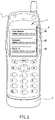
- FIG. 2 is a schematic view of a user interface of the present invention.
- FIG. 3 is a flow chart of switching communication modes of the present invention.
- a communication device 1 has a connecting port 10 , at its surface; a connecting port 10 connects to an external communication module 2 ; the communication device 1 further comprises a control module 12 and a built-in communication module 14 ; the control module 12 connects to the connecting port 10 and the built-in communication module 14 ; the external communication module 2 and built-in communication module 14 are matched with different communication systems respectively, such that the communication device 1 uses the control module 12 to determine the connection status between the connecting port 10 and an external communication module, and the control module 12 bases on the connection status to simultaneously activate both external communication module 2 and the built-in communication module 14 or just activate one of them.
- the communication device 1 further comprises a user operating module 16 , and the user operating module 16 connects to the control module 12 ; the communication device 1 confirms the connection of the connecting port 10 with the external communication module 2 through the control module 12 ; the control module 12 uses the user operating module 16 to display the user interface 4 on a display unit 3 of the communication device 1 ; after the user interface 4 is operated, the user operating module 16 generates an activation signal, the activation signal is transmitted to the control module 12 through the user interface 4 .
- the control module 12 activates the external module 2 and the built-in communication module 14 based on activation signal to activate either both external module 2 and the built-in communication module 14 or one of them.
- users can select their desired communication mode flexibly.
- the user interface 4 has a simultaneous activation option 40 , an external communication activation option 42 and a built-in communication activation option 44 , and the control module 12 switches the communication modes according to following procedure:
- Step 301 determines whether or not the simultaneous activation option 40 is selected; if yes, go to Step 302 , or else go to Step 303 ;
- Step 302 the user operating module 16 generates a match signal while activating the simultaneous activation option 40 , and the control module 12 bases on a simultaneous activation signal to activate both external module 2 and built-in communication module 14 ;
- Step 303 determines whether or not the external communication activation option 42 is selected, if yes, go to Step 304 , or else go to Step 305 ;
- Step 304 the user operating module 16 generates a match signal while activating the external communication activation option 42 , and the control module 12 bases on an external activation signal to activate the external module 2 ;
- Step 305 determines whether or not the built-in communication activation option 44 is selected; if yes, go to Step 306 , or else go to Step 301 ;
- Step 306 the user operating module 16 generates a match signal while activating the built-in communication activation option 44 , and the control module 12 employs a built-in activation communication signal to activate the built-in communication module 14 .
- a timer 18 is built in the communication device 1 , and the timer 18 can set a first wait time.
- the control module 12 reads the first wait time by reading the timer 18 ; and the control module 12 will wait when the first wait time has elapsed and the connecting port 10 hasn't been connected to the external communication module 2 , then the control module 12 will activate the built-in communication module 14 automatically.
- the timer 18 can set two wait times, and the control module 12 reads a second wait time from the timer 18 .
- the control module 12 will activates the built-in communication module 14 when the second wait time has elapsed and the activation signal hasn't been received.
- the communication device 1 allows users to selectively activate both external module 2 and the built-in communication module 14 , or activate either one of them. After the communication device 1 is not connected to the external module 2 or any communication module 14 , 2 for a predetermined time, the communication device 1 will activate the built-in communication module 14 directly. Users can choose either the external module 2 or the built-in communication module 14 flexibly based on actual needs.
- the communication device 1 only has a built-in communication module 14 , so that the physical size of the communication device 1 will not be too bulky, which can solve the size problem of the traditional dual-mode mobile phones.
Abstract
Description
Claims (6)
Applications Claiming Priority (2)
| Application Number | Priority Date | Filing Date | Title |
|---|---|---|---|
| TW093138701 | 2004-12-14 | ||
| TW093138701A TW200621040A (en) | 2004-12-14 | 2004-12-14 | Method for switching communication module on communication device |
Publications (2)
| Publication Number | Publication Date |
|---|---|
| US20060128432A1 US20060128432A1 (en) | 2006-06-15 |
| US7558601B2 true US7558601B2 (en) | 2009-07-07 |
Family
ID=36584708
Family Applications (1)
| Application Number | Title | Priority Date | Filing Date |
|---|---|---|---|
| US11/167,084 Active 2027-08-14 US7558601B2 (en) | 2004-12-14 | 2005-06-28 | Method of switching communication modes of a communication device |
Country Status (2)
| Country | Link |
|---|---|
| US (1) | US7558601B2 (en) |
| TW (1) | TW200621040A (en) |
Citations (6)
| Publication number | Priority date | Publication date | Assignee | Title |
|---|---|---|---|---|
| US6078825A (en) * | 1998-02-20 | 2000-06-20 | Advanced Mobile Solutions, Inc. | Modular wireless headset system for hands free talking |
| US6580921B1 (en) * | 1997-03-04 | 2003-06-17 | Mitsubishi Denki Kabushiki Kaisha | Dual-mode mobile telephone terminal |
| US6724680B1 (en) * | 2003-06-10 | 2004-04-20 | Phison Electronics Corp. | Single integrated circuit flash memory controller for activating external ROM sharing a common USB port |
| US20040116155A1 (en) * | 2002-12-12 | 2004-06-17 | Alain Aisenberg | Cellular telephone back-up and media system |
| US20040266480A1 (en) * | 2003-06-27 | 2004-12-30 | Hjelt Kari Tapani | System and method for implementing sensor functionality in mobile devices |
| US7433712B2 (en) * | 2003-02-06 | 2008-10-07 | Modu Ltd. | Multi-access solid state memory devices and a telephone utilizing such |
-
2004
- 2004-12-14 TW TW093138701A patent/TW200621040A/en not_active IP Right Cessation
-
2005
- 2005-06-28 US US11/167,084 patent/US7558601B2/en active Active
Patent Citations (6)
| Publication number | Priority date | Publication date | Assignee | Title |
|---|---|---|---|---|
| US6580921B1 (en) * | 1997-03-04 | 2003-06-17 | Mitsubishi Denki Kabushiki Kaisha | Dual-mode mobile telephone terminal |
| US6078825A (en) * | 1998-02-20 | 2000-06-20 | Advanced Mobile Solutions, Inc. | Modular wireless headset system for hands free talking |
| US20040116155A1 (en) * | 2002-12-12 | 2004-06-17 | Alain Aisenberg | Cellular telephone back-up and media system |
| US7433712B2 (en) * | 2003-02-06 | 2008-10-07 | Modu Ltd. | Multi-access solid state memory devices and a telephone utilizing such |
| US6724680B1 (en) * | 2003-06-10 | 2004-04-20 | Phison Electronics Corp. | Single integrated circuit flash memory controller for activating external ROM sharing a common USB port |
| US20040266480A1 (en) * | 2003-06-27 | 2004-12-30 | Hjelt Kari Tapani | System and method for implementing sensor functionality in mobile devices |
Also Published As
| Publication number | Publication date |
|---|---|
| TW200621040A (en) | 2006-06-16 |
| TWI293849B (en) | 2008-02-21 |
| US20060128432A1 (en) | 2006-06-15 |
Similar Documents
| Publication | Publication Date | Title |
|---|---|---|
| Neuvo | Cellular phones as embedded systems | |
| US8364139B2 (en) | Personal area network systems and devices and methods for use thereof | |
| US20070129103A1 (en) | Cellular phone having multiple lines | |
| US20080261528A1 (en) | Personal area network systems and devices and methods for use thereof | |
| JPH08293830A (en) | Portable telephone set and display adapter | |
| US20030169860A1 (en) | Multi-port multi-channel bi-directional communication device | |
| US20050176466A1 (en) | Method and apparatus of verifying and managing multiple systems in a wireless communications device | |
| US20060019643A1 (en) | Method of sending instruction to mobile phone by short message | |
| US8380156B2 (en) | Mobile wireless communications device having buffered clock distribution network for microprocessor and RF circuits | |
| US7558601B2 (en) | Method of switching communication modes of a communication device | |
| US7162270B2 (en) | Dual communication mode wireless network transmission device | |
| KR20020044176A (en) | System and method for indicating connection properties for a call placed via a wireless handset | |
| US6755343B1 (en) | Electronic card capable of changing communication functionality of a coupled electronic device | |
| WO2008107732A1 (en) | Wireless communication device and method for communicating with two different communication channels | |
| JP2000261857A (en) | Portable telephone set | |
| KR100421929B1 (en) | Cellular phone capable of communicating by bluetooth protocol | |
| CN100466777C (en) | Method of switching communication module in communication devices | |
| KR100622838B1 (en) | Menu system for a radiotransmission apparatus | |
| KR100686010B1 (en) | Apparatus and method for suppling wire communication of mobile phone | |
| KR100594460B1 (en) | Mobile communication terminal of the WiFi type having a voltage source control function and controlling method therefore | |
| KR100594440B1 (en) | USB port device of the mobile communication terminal having a priority and controlling method therefore | |
| KR100597132B1 (en) | Multimedia mobile phone and high speed wiress communication method using the same | |
| KR100414773B1 (en) | The detachable flash rom card module and the pcmcia wireless modem including above detachable flash rom card module | |
| CA2567542C (en) | Mobile wireless communications device having buffered clock distribution network for microprocessor and rf circuits | |
| PL1585250T3 (en) | Method and system for charging for telecommunications services |
Legal Events
| Date | Code | Title | Description |
|---|---|---|---|
| AS | Assignment |
Owner name: INVENTEC APPLIANCE CORP., TAIWAN Free format text: ASSIGNMENT OF ASSIGNORS INTEREST;ASSIGNORS:LAI, CHENG-SHING;GU, PING;LIU, PENG-HUI;REEL/FRAME:016738/0510 Effective date: 20050314 |
|
| STCF | Information on status: patent grant |
Free format text: PATENTED CASE |
|
| CC | Certificate of correction | ||
| FPAY | Fee payment |
Year of fee payment: 4 |
|
| FEPP | Fee payment procedure |
Free format text: PAYOR NUMBER ASSIGNED (ORIGINAL EVENT CODE: ASPN); ENTITY STATUS OF PATENT OWNER: LARGE ENTITY |
|
| FPAY | Fee payment |
Year of fee payment: 8 |
|
| AS | Assignment |
Owner name: INVENTEC APPLIANCES CORP., TAIWAN Free format text: CORRECTIVE ASSIGNMENT TO CORRECT THE ASSIGNEE'S NAME PREVIOUSLY RECORDED AT REEL: 016738 FRAME: 0510. ASSIGNOR(S) HEREBY CONFIRMS THE ASSIGNMENT;ASSIGNORS:LAI, CHENG-SHING;GU, PING;LIU, PENG-HUI;REEL/FRAME:044368/0446 Effective date: 20050314 |
|
| AS | Assignment |
Owner name: INVENTEC APPLIANCES (JIANGNING) CORPORATION, CHINA Free format text: ASSIGNMENT OF ASSIGNORS INTEREST;ASSIGNOR:INVENTEC APPLIANCES CORP.;REEL/FRAME:044713/0446 Effective date: 20171019 |
|
| FEPP | Fee payment procedure |
Free format text: PETITION RELATED TO MAINTENANCE FEES GRANTED (ORIGINAL EVENT CODE: PTGR) |
|
| AS | Assignment |
Owner name: BEIJING XIAOMI MOBILE SOFTWARE CO., LTD., CHINA Free format text: ASSIGNMENT OF ASSIGNORS INTEREST;ASSIGNOR:INVENTEC APPLIANCES (JIANGNING) CORPORATION;REEL/FRAME:049027/0839 Effective date: 20171211 |
|
| MAFP | Maintenance fee payment |
Free format text: PAYMENT OF MAINTENANCE FEE, 12TH YEAR, LARGE ENTITY (ORIGINAL EVENT CODE: M1553); ENTITY STATUS OF PATENT OWNER: LARGE ENTITY Year of fee payment: 12 |