US7548357B2 - Image processing device, image display device, image processing method, and image processing program - Google Patents
Image processing device, image display device, image processing method, and image processing program Download PDFInfo
- Publication number
- US7548357B2 US7548357B2 US11/022,988 US2298804A US7548357B2 US 7548357 B2 US7548357 B2 US 7548357B2 US 2298804 A US2298804 A US 2298804A US 7548357 B2 US7548357 B2 US 7548357B2
- Authority
- US
- United States
- Prior art keywords
- saturation
- enhancement
- amount
- color
- image data
- Prior art date
- Legal status (The legal status is an assumption and is not a legal conclusion. Google has not performed a legal analysis and makes no representation as to the accuracy of the status listed.)
- Expired - Fee Related, expires
Links
Images


Classifications
-
- F—MECHANICAL ENGINEERING; LIGHTING; HEATING; WEAPONS; BLASTING
- F24—HEATING; RANGES; VENTILATING
- F24F—AIR-CONDITIONING; AIR-HUMIDIFICATION; VENTILATION; USE OF AIR CURRENTS FOR SCREENING
- F24F7/00—Ventilation
- F24F7/007—Ventilation with forced flow
- F24F7/013—Ventilation with forced flow using wall or window fans, displacing air through the wall or window
-
- G—PHYSICS
- G09—EDUCATION; CRYPTOGRAPHY; DISPLAY; ADVERTISING; SEALS
- G09G—ARRANGEMENTS OR CIRCUITS FOR CONTROL OF INDICATING DEVICES USING STATIC MEANS TO PRESENT VARIABLE INFORMATION
- G09G5/00—Control arrangements or circuits for visual indicators common to cathode-ray tube indicators and other visual indicators
- G09G5/02—Control arrangements or circuits for visual indicators common to cathode-ray tube indicators and other visual indicators characterised by the way in which colour is displayed
-
- F—MECHANICAL ENGINEERING; LIGHTING; HEATING; WEAPONS; BLASTING
- F24—HEATING; RANGES; VENTILATING
- F24F—AIR-CONDITIONING; AIR-HUMIDIFICATION; VENTILATION; USE OF AIR CURRENTS FOR SCREENING
- F24F13/00—Details common to, or for air-conditioning, air-humidification, ventilation or use of air currents for screening
- F24F13/08—Air-flow control members, e.g. louvres, grilles, flaps or guide plates
- F24F13/082—Grilles, registers or guards
-
- F—MECHANICAL ENGINEERING; LIGHTING; HEATING; WEAPONS; BLASTING
- F24—HEATING; RANGES; VENTILATING
- F24F—AIR-CONDITIONING; AIR-HUMIDIFICATION; VENTILATION; USE OF AIR CURRENTS FOR SCREENING
- F24F13/00—Details common to, or for air-conditioning, air-humidification, ventilation or use of air currents for screening
- F24F13/20—Casings or covers
-
- F—MECHANICAL ENGINEERING; LIGHTING; HEATING; WEAPONS; BLASTING
- F24—HEATING; RANGES; VENTILATING
- F24F—AIR-CONDITIONING; AIR-HUMIDIFICATION; VENTILATION; USE OF AIR CURRENTS FOR SCREENING
- F24F13/00—Details common to, or for air-conditioning, air-humidification, ventilation or use of air currents for screening
- F24F13/28—Arrangement or mounting of filters
-
- H—ELECTRICITY
- H04—ELECTRIC COMMUNICATION TECHNIQUE
- H04N—PICTORIAL COMMUNICATION, e.g. TELEVISION
- H04N9/00—Details of colour television systems
- H04N9/64—Circuits for processing colour signals
- H04N9/68—Circuits for processing colour signals for controlling the amplitude of colour signals, e.g. automatic chroma control circuits
-
- G—PHYSICS
- G09—EDUCATION; CRYPTOGRAPHY; DISPLAY; ADVERTISING; SEALS
- G09G—ARRANGEMENTS OR CIRCUITS FOR CONTROL OF INDICATING DEVICES USING STATIC MEANS TO PRESENT VARIABLE INFORMATION
- G09G2320/00—Control of display operating conditions
- G09G2320/02—Improving the quality of display appearance
- G09G2320/0242—Compensation of deficiencies in the appearance of colours
-
- G—PHYSICS
- G09—EDUCATION; CRYPTOGRAPHY; DISPLAY; ADVERTISING; SEALS
- G09G—ARRANGEMENTS OR CIRCUITS FOR CONTROL OF INDICATING DEVICES USING STATIC MEANS TO PRESENT VARIABLE INFORMATION
- G09G2320/00—Control of display operating conditions
- G09G2320/06—Adjustment of display parameters
- G09G2320/0666—Adjustment of display parameters for control of colour parameters, e.g. colour temperature
Definitions
- aspects of the invention can relate to an image processing technique which corrects the saturation of color images.
- a correcting process can be performed in order to enhance the saturation.
- saturation enhancement process are disclosed in, for example, Japanese Unexamined Patent Application Publication No. 2001-218078.
- the saturation correction table is set so as to have a curve in which the saturation of the output image data becomes larger than the saturation of the input image data. Therefore, the saturation is corrected by using the saturation correction table. Since the saturation correction table is made after previously detecting the maximum saturation, output after the saturation correction does not exceed the maximum saturation, that is, the color deformation does not occur.
- aspects of the invention can provide an image processing technique which is capable of performing a saturation enhancement with a well balance between color components and a reduced calculation amount.
- an image processing device including a saturation-enhancement-amount determining device for determining the saturation enhancement amount by extracting saturation information from input image data, a color component extracting device for extracting from the input image data a plurality of color components having saturation to be enhanced, a saturation enhancing device for enhancing the saturations of the plurality of color components based on the determined saturation enhancement amount, and an enhancement-amount adjusting device for adjusting the determined saturation enhancement amount when enhancing a saturation of a predetermined color component among the plurality of color components.
- the image processing device can be provided in an image display device.
- the image processing device can be provided as a device for providing display image data to the external image display device. More specifically, saturation information is extracted from input image data to determine the saturation enhancement amount. Further, a color component enhancing the saturation is extracted from the input image data. In addition, the saturation enhancement with respect to the respective color components can be performed based on the determined saturation enhancement amount.
- the saturation is enhanced after the saturation enhancement amount is adjusted.
- the color components included in the input image data can be, for example, Cb and Cr in an YCbCr color space. For the predetermined color components, a color balance of image data after the saturation enhancement can be properly adjusted by adjusting the saturation enhancement amount so that the natural color data can be obtained.
- One aspect of the image processing device can include a brightness information extracting device for extracting from the input image data brightness information, and the enhancement-amount adjusting device can adjust the saturation enhancement amount based on the extracted brightness information.
- the saturation is enhanced, the effect of the saturation enhancement can be given based on the brightness of the input image data, for a specific color component.
- the effect of the saturation enhancement is reduced when a blue component corresponding to a positive direction of the Cb component is clipped in case that the brightness is high.
- a yellow component corresponding to a negative direction is not clipped and the effect of the saturation enhancement can be given as arranged, so that the color balance may not be achieved. For this reason, the color balance can be achieved by adjusting the saturation enhancement amount based on brightness information for the predetermined color component.
- the enhancement-amount adjusting device can reduce the saturation enhancement amount when the brightness included in the extracted brightness information is high.
- the saturation enhancement amount is reduced in the negative direction of the Cb component. Therefore, the enhancement of the positive and negative directions of the Cb component (i.e., blue component and yellow component) can be adjusted to be equal so that the color balance can be maintained.
- the enhancement-amount adjusting device can adjust the saturation enhancement amount such that the enhancement amount of the negative region of the predetermined color component for a color space is smaller than the enhancement amount in at positive region thereof.
- the enhancement-amount adjusting device makes the enhancement amount in the negative direction of the predetermined color component to be equal to an enhancement amount in the positive direction multiplied by a coefficient ⁇ (0 ⁇ 1).
- the coefficient ⁇ is a fixed value, and as the average value of the brightness information becomes larger, the average value can be reduced smaller than the fixed value.
- the image processing device can include a brightness correcting device for correcting the brightness component included in the input image data.
- the coefficient ⁇ is considered as a fixed value irrespective of the brightness information.
- the saturation enhancement amount having a color component (i.e., yellow component) corresponding the negative direction of the Cb component, for example may be uniformly reduced so that the color balance can be maintained.
- the predetermined color component for the color space may be a Cb color component in a YCbCr color space.
- the input image data can be a moving image data including a plurality of frame image data
- scene-change detecting device for generating a control signal according to a degree of changing data scene of the moving image data may be included.
- the enhancement-amount adjusting device weights the coefficient ⁇ corresponding to the plurality of frame images based on the control signal to calculate the coefficient ⁇ in the corresponding frame image. With this, even for the prior and next scene change, the appropriate coefficient ⁇ can be determined so that the natural saturation enhancement can be achieved.
- the input image data can be displayed such that the color balance is achieved while the saturation enhancement is performed.
- an image processing method including a saturation enhancement amount determining step of determining the saturation enhancement amount by extracting saturation information from input image data, a color component extracting step of extracting from the input image data a plurality of color components having saturation to be enhanced, a saturation enhancing step of enhancing the saturations of the plurality of color components based on the determined saturation enhancement amount, and an enhancement-amount adjusting step of adjusting the determined saturation enhancement amount when enhancing a saturation of a predetermined color component among the plurality of color components.
- an image processing program which can be executed by a computer and which allows the computer function as a saturation-enhancement-amount determining device for determining the saturation enhancement amount by extracting from input image data saturation information, a color component extracting device for extracting from the input image data a plurality of color components having saturation to be enhanced, a saturation enhancing device of enhancing the saturations of the plurality of color components based on the determined saturation enhancement amount, and an enhancement-amount adjusting device for adjusting the determined saturation enhancement amount when enhancing a saturation of a predetermined color component among the plurality of color components.
- FIG. 1 shows a distribution of pixel values in a color space
- FIG. 2 shows a distribution of pixel values in a Y-Cb plane
- FIG. 3 shows a distribution of pixel values in a Y-Cr plane
- FIG. 4 shows change in the pixel values based on the transformation curve of the saturation
- FIG. 5 shows change of the frequency distribution based on the transformation curve of the saturation
- FIG. 6 shows change in pixel values of an image having a large brightness value
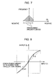
- FIG. 7 shows a frequency distribution of a pixel value when a clip is occurred
- FIG. 8 shows an example of a transformation curve suppressing an enhancement amount of a Cb component
- FIG. 9 shows a frequency distribution of a pixel value when the enhancement amount of the Cb component is suppressed
- FIG. 10 shows an example of determining an adjusting parameter
- FIG. 11 is an exemplary block diagram showing a schematic arrangement of an image display device of the invention.
- FIG. 12 is a flow chart of an exemplary tone correction process according to a first exemplary embodiment of the invention.
- FIG. 13 is a diagram illustrating a sampling region
- FIG. 14 is an example of a histogram for brightness
- FIG. 15 is a graph showing an example of calculating a saturation enhancement amount
- FIG. 16 is an example of a saturation correction table
- FIG. 17 shows an example of determining the adjusting parameter according to the first exemplary embodiment of the invention
- FIG. 18 is a flow chart of a tone correction process according to the second exemplary embodiment of the invention.
- FIG. 19 is an example of calculating an amount of brightness correction
- FIG. 20 is an example of determining a brightness correction point
- FIG. 21 is an example of a brightness correction table
- FIG. 22 shows an example of determining the adjusting parameter according to the second exemplary embodiment of the invention.
- FIG. 23 is a flow chart of an exemplary tone correction process according to the third exemplary embodiment of the invention.
- FIG. 1 shows a state where pixel values of an input image are distributed in a color space.
- YCbCr color space is used as the color space.
- Y represents a brightness (luminance) component
- Cb, Cr represent color components. Since Cb and Cr are components indicating colors, as the absolute value becomes large, more vivid colors are obtained.
- FIG. 2 and FIG. 3 show distribution of the pixel values in a Y-Cb plane and a Y-Cr plane, respectively. The range of the pixel values is extended to the outside range along the arrow, in FIG. 2 and FIG. 3 . In this case, since the absolute value of Cb, Cr increase, the color vividness is improved (that is, the saturation is enhanced).
- the saturation enhancement can be substantially performed according to the transformation curve shown in FIG. 4 .
- the transformation curve has an approximate S-shape, which passes through the origin, in which the horizontal axis is input, and the vertical axis is output. If the transformation of the pixel value of Cb, Cr is performed according to the transformation curve, it is possible to increase the absolute value.
- the change in absolute value can be shown as change in the frequency distribution shown in FIG. 5 .
- the horizontal axis represents pixel values of Cb (or Cr), and the vertical axis represents the frequency at the pixel values.
- the absolute value becomes large according to the transformation curve, and as a result, the frequency distribution extends to both sides thereof. Further, the frequency distribution changes according to the saturation enhancement, but the total number of pixels do not change. Since the frequency distribution shows the distribution of the color components, what the frequency distribution extends as shown in FIG. 5 means that the color enhancement is performed.
- FIG. 6 shows distribution of pixel values of another input image, viewed from Y-Cb plane.
- the characteristic of the input image is that the brightness value Y is relatively large.
- the pixel value protrudes outside the color space. Since values outside the color space are not practically selected, a value on the boundary of the color space is taken (selected) (to take the value on the boundary is referred to that clip (cutting) is occurred at the boundary.
- FIG. 7 shows a frequency distribution when the clip has occurred.
- YCbCr color space is narrow in the positive direction of Cb, and is broad in the negative direction of Cb. Therefore, as shown in FIG. 6 , most of clips generates in the positive region of Cb, the frequency distribution in the positive region of Cb is limited to a range having a fixed value. Specifically, since the color space in the negative region of Cb is broad, the clip can be difficult to occur, and thus the spread of the frequency distribution is large.
- the YCbCr space in a high-brightness region, has a tendency to be narrow in the positive direction of Cr and in the negative direction of Cr, which is similar to that of Cb.
- the positive region of Cr in the YCbCr color space in the high-brightness region, does not so narrow as the positive region of Cb. Therefore, the above-mentioned clip does not matter in Y-Cr space as much as that in Y-Cb space.
- FIG. 8 shows a modified transformation curve, which suppresses the enhancement amount in the negative direction of Cb.
- a coefficient ⁇ (0 ⁇ 1) (adjusting coefficient) is determined to suppress the enhancement amount in the negative direction of Cb larger than the normal value A or the enhancement amount in the positive direction of Cb.
- FIG. 9 shows a frequency distribution when the saturation is enhanced using the transformation curve of FIG. 8 .
- the spread of the distribution due to the clip does not increase more than a constant value.
- the enhancement amount is suppressed due to the coefficient ⁇ introduced earlier as shown in FIG. 8 , the spread of the distribution does not increase.
- the same level of saturation enhancement can be given both in the positive and negative directions, so that the color balance can be prevented from collapse.
- the clip is generated in the positive direction of Cb for an image having a high brightness in particular, as shown in FIG. 6 . Therefore, it is desirable that the indicated coefficient ⁇ (0 ⁇ 1) has a relation to the brightness value of the input image. In fact, since the brightness of the input image has a distribution, an average brightness is used as a representative value.
- FIG. 10 shows a diagram for setting the coefficient ⁇ , by taking the average value of the brightness as a horizontal axis and the coefficient ⁇ as a vertical axis. As the average value of the brightness increases, the coefficient ⁇ is set to decrease.
- the invention suppresses the enhancement amount in the negative direction of Cb.
- the color balance in the positive and negative directions of Cb can be adjusted and the natural saturation enhancement is achieved.
- FIG. 11A shows an exemplary schematic diagram of an image display device 100 .
- the image display device 100 may be a device for processing and displaying an external input image data, an AV appliance or a terminal having an image display function.
- the saturation correcting process of the invention can be characterized in a smaller amount of calculation.
- the invention can be particularly suitable for a portable terminal device, such as a mobile phone or a PDA, which have such amount of processing capacity.
- the image display device 100 can include an image processing device 10 for performing an image process including a saturation correction process and a display unit 20 for displaying the processed image.
- the image processing device 10 may include a CPU 11 , a ROM 12 for storing an image processing program, and a RAM 13 as an operating memory, as shown in FIG. 11B .
- the saturation correcting process according to the present invention may be performed is such a manner that the process is stored in the ROM 12 as an image process program and the CPU 11 reads the program.
- the image process including the saturation correcting process is not performed in software but may be performed by processing a part or all of the process in hardware.
- the display unit 20 may be a type of the image display device 100 .
- a liquid crystal panel and other flat panel display can also be used as the display unit 20 .
- the saturation correcting process according to the first exemplary embodiment will be described.
- the enhancement amount in the negative region of the Cb component in the YCbCr space as described is suppressed so that the favorable saturation correction with a satisfactory color balance can be performed.
- FIG. 12 shows a flow chart of a saturation correcting process according to the first exemplary embodiment of the invention.
- the saturation correcting process of the first embodiment can be performed by calculating a statistic amount of input image data, extracting features of the input image data, making a correction table based on the extracted features, and correcting the saturation of the input image data by using the correction table.
- the input image data is sampled to make a histogram (step S 1 ).
- the image processing device 10 can convert the RGB input image data (including R, G, and B) into the YCbCr input image data (including Y, Cb, and Cr) according to equations 1 and 2 below.
- Equation 1 can be used to convert the RGB-type image data into the YCbCr-type image data, and equation 2 is a transformation matrix M thereof.
- FIGS. 13A and 13B show examples of the sampling region where the images are extracted by sampling.
- entire frame image becomes the sampling region.
- a total frequency due to the sampling is a total pixel number Rx ⁇ Ry.
- FIG. 13B is an example of a sampling region only for a central area of the frame image. Assuming the horizontal and vertical sizes of the image are Rx and Ry and a ratio of the central area to the overall image is R, the horizontal and vertical sizes of the central area Ra and Rb can be found as shown in equation 3.
- Equation ⁇ ⁇ 4 A ⁇ : ⁇ ⁇ ( R x - R a 2 , R y - R b 2 ) ⁇ ⁇ B ⁇ : ⁇ ⁇ ( R x + R a 2 , R y - R b 2 ) ( 4 ) C ⁇ : ⁇ ⁇ ( R x - R a 2 , R y + R b 2 ) ⁇ ⁇ D ⁇ : ⁇ ⁇ ( R x + R a 2 , R y + R b 2 )
- a histogram f A (k) of the brightness Y, and the histogram f S (k) of the saturation S can be drawn as the following equation 5.
- the saturation S can be found from the color difference signals Cb and Cr, as described in equation 6.
- FIG. 14 shows an example of the histogram obtained from the above description.
- the horizontal axis refers to gray level scale levels (0 to 255) and the vertical axis refers to a frequency (pixel number having each gray level scale level).
- the histogram for the saturation S can be drawn.
- the statistic amount can be calculated (step S 2 ). Specifically, the average values P Aave and P Save are calculated from the histogram f A (k) of the brightness Y and the histogram f S (k) of the saturation S according to equation 7, respectively.
- a correcting parameter used in the saturation correction can be calculated based on the obtained statistic amount (step S 3 ). Specifically, using the saturation average value P Save , a saturation enhancement amount P Sdiff ′ is calculated according to equation 8.
- P Sdiff ′ ⁇ P Sdiff , P Sdiff ⁇ P Sth P Sth , P Sdiff > P Sth ( 8 )
- P Sdiff ⁇ ( P Saveth - P Save ) ⁇ P Scv ⁇ 1 / P Scv ⁇ 2 , P Save ⁇ P Saveth 0 , P Save ⁇ P Saveth
- FIG. 15 shows a relationship between the saturation average value P Save and the acquired saturation enhancement amount P Sdiff ′.
- the saturation enhancement amount P Sdiff ′ is set to be large, and as the saturation average value P Save exceeds the predetermined value, the saturation enhancement amount P Sdiff ′ is set to 0 (that is, no enhancement). Accordingly, the region having a lower saturation can be enhanced.
- FIG. 16A shows an example of the correction table S[Cr], which has a Cr component.
- the correction table S[Cr] is made as a curve passing (0,0), ( ⁇ 128, ⁇ 128), (128, 128), a correction point 1 (P Spt , P Spt ′), and a correction point 2 ( ⁇ P Spt , ⁇ P Spt ′).
- a proper interpolation function such as a spline interpolation is used to make a curve.
- the correction points 1 and 2 are symmetric to the original point, and the correction table S[Cr] is also symmetric to the original point.
- the output of the correction point P Spt ′ can be found using the input P Spt and the saturation enhancement amount P Sdiff ′ as the following equation 9.
- the same saturation enhancement amount P Sdiff ′ can be used for the positive and negative regions of the input data.
- the correction table S[Cb] having a color component Cb is similarly configured, for a case where the brightness of the input image data is high as described above, if the Cb component is clipped in the positive region, the negative region of the Cb component becomes relatively strong so that the color balance is collapsed. Therefore, according to the present invention, an adjusting parameter ⁇ is introduced in the negative region of the correction table S[Cb] and the saturation enhancement amount is P Sdiff ′ ⁇ S .
- FIG. 16B shows an example of the correction table S[Cb].
- the output of the correction point P Spt ′ herein can be obtained using the input P Spt , the saturation enhancement amount P Sdiff ′, and the adjusting parameter ⁇ S as shown in equation 9.
- the adjusting parameter ⁇ S is 0 ⁇ S ⁇ 1, so that the enhancement amount of the negative region of the Cb component of the correction table is smaller than the enhancement amount of the positive region, as shown in FIG. 16B . Therefore, the enhancement of the negative region of the Cb component can be further suppressed compared with the enhancement of other color components so that the color balance can be prevented from collapse.
- the color is corrected (step S 5 ).
- the tone correction is performed for each pixel of the input image data.
- the corrected image data Y′, Cb′, and Cr′ are obtained according to equation 10 by using the correction table S[Cb] and S[Cr], and converted into the RGB type image data R′, G′ and B′.
- the brightness Y is not corrected.
- the saturation correcting process is completed.
- FIG. 17 shows an example of a graph of ⁇ S .
- the horizontal axis represents a brightness average value P Aave , which shows that the adjusting parameter ⁇ S is reduced when the brightness average value P Aave exceeds the predetermined value.
- the value of ⁇ S in FIG. 17 can be obtained from equation 11.
- the adjusting parameter ⁇ S is linearly reduced (monotonically reduced) from a point where the brightness average value P Aave exceeds the predetermined value, in the example of FIG. 17 , the adjusting parameter ⁇ S may be non-linearly reduced (logarithmically reduced).
- the second exemplary embodiment of the invention will be described.
- the case where only the saturation is corrected as a tone correction processing has been described in the first embodiment of the present invention.
- the brightness in addition to the saturation is corrected at the same time.
- the method of correcting saturation is the same as that described in the first exemplary embodiment.
- FIG. 18 is a flowchart of the tone correction process according to the second exemplary embodiment of the invention. Similar to the first embodiment, first, the input image data is sampled to obtain a histogram over the brightness Y and the saturation S (step S 11 ). Based on the histogram, the statistic amount of the brightness Y and the saturation S are calculated (step S 12 ).
- the adjusting parameter is calculated (step S 13 ).
- the correcting parameter P Sdiff ′ of the saturation S is shown in FIG. 15 , which can be obtained from equation 8, similar to the first embodiment.
- the correcting parameter (gamma adjusting parameter) P Gdiff ′ of the brightness Y can be obtained from equation 12, as shown in FIG. 19 .
- FIG. 19 shows a relation between the average value P Aave ′ and the correcting parameter P Gdiff ′.
- P Gdiff ′ ⁇ P Gth ⁇ ⁇ 1 , P Gdiff ⁇ P Gth ⁇ ⁇ 1 P Gdiff , P Gth ⁇ ⁇ 1 ⁇ P Gdiff ⁇ P Gth ⁇ ⁇ 2 P Gth ⁇ ⁇ 2 , P Gth ⁇ ⁇ 2 ⁇ P Gdiff ( 12 )
- P Gdiff ( P Aaveth - P Aave ′ ) ⁇ P Gcv ⁇ ⁇ 1 / P Gcv ⁇ ⁇ 2
- P Gaveth is a reference value of the correction
- P Gcv1 and P Gcv2 are parameters for adjusting the correction amount
- P Gth1 and P Gth2 are limiters for limiting the correction amount.
- the reference value of the correction P Gaveth is determined such that the correction for darkening the brightness is used when the average value P Aave ′ becomes larger than the reference value of the correction P Gaveth while the correction for brightening the brightness is used when the average value P Aave ′ is smaller than the reference value of the correction P Gaveth .
- the correction table is calculated based on the adjusting parameter of the brightness Y and the saturation S (step S 14 ).
- the correction table of the saturation S is configured in the same manner as the first embodiment.
- the correction point P Gpt of the brightness Y is given as the following equation 13, as shown in FIG. 20 .
- the tone is corrected using the correction table for the brightness Y and the saturation S (step S 15 ).
- the corrected brightness Y′, and the color differences Cb′ and Cr′ are calculated according to equation 15, and converted into the RGB-type image data R′, G′, and B′.
- the adjusting parameter ⁇ S is gradually reduced to more than the predetermined average value of the brightness P Aave ′, as shown in FIG. 17 .
- the adjusting parameter ⁇ S is fixed to the predetermined value ⁇ th , as shown in FIG. 22 .
- the brightness as well as the saturation is corrected.
- the average value of the brightness P Aave ′ is small, i.e., when the image is dark, the correction to brighten the image is performed.
- the clip is hardly generated so that the adjusting parameter ⁇ S is set to be 1.
- the correction to brighten image is performed on the dark image by the brightness correction, so that the color component Cb may probably be clipped in the positive direction by using the saturation correction.
- the adjusting parameter ⁇ S is fixed to the predetermined value ⁇ th (0 ⁇ th ⁇ 1).
- the color is preferably balanced such that the color component of the negative region of the Cb (i.e., yellow component) is further suppressed.
- the adjusting parameter ⁇ S may be gradually increased from the predetermined value ⁇ th in the region above the predetermined average value of the brightness P Aave as shown by a broken line C 1 in FIG. 22 .
- the correction is performed on the dark image.
- the chance that the color component Cb is clipped in the positive direction due to the saturation correction is reduced.
- the scene change is detected to update the adjusting parameter ⁇ S .
- the correcting parameter at the time when the scene (situation) is significantly changed is used (dynamically update the correcting parameter).
- the same parameter is preferably used (the adjusting parameter is not dynamically updated) to prevent flickering.
- the adjusting parameter ⁇ S of the saturation correction is updated according to the detection result of the scene change. Specifically, the weighted average of the adjusting parameter for continuous moving image frame is found, and the weight of the weighted average is adjusted according to the detection result of the scene change.
- the weighted adjusting parameter ⁇ can be represented as follows.
- the adjusting parameter ⁇ after calculating the weighted average based on equation 17 becomes the adjusting parameter for the current frame image ⁇ S1 so that the adjusting parameter at that point is updated.
- the correction optimal to the scene change can be performed.
- the adjusting parameter ⁇ after calculating the weighted average is simply averaged by equation 17, so that a temporal minute change of the adjusting parameter can be removed. As a result, the disturbance, such as flickering after the correction, can be reduced.
- the invention has been described in the context of detecting whether the scene is changed, it is also possible to calculate the degree of the scene change and successively control the weights of the weighted average according to the degree of change.
- the scene change is detected, and the weighted average of the saturation adjusting parameter ⁇ can be obtained according to the detection result of the scene change. Therefore, even when the input image data is the moving image, the proper saturation correction can be performed.
- FIG. 23 shows a flowchart of an exemplary tone correction processing according to the third embodiment of the invention. Further, while only the saturation correction is performed as a tone correction in the third embodiment, which is similar to the first embodiment, the third exemplary embodiment can also be used for correcting the brightness as well as the saturation, as described in the second exemplary embodiment.
- steps S 21 to S 23 are the same as the steps S 1 to S 3 of the first embodiment.
- the input image data which is a moving image in this example, is sampled for each frame image to make the histogram (step 21 ).
- the statistic amount is calculated (step S 22 ) and the correction parameter is calculated (step S 23 ).
- step S 24 the processing of changing scenes is performed (step S 24 ).
- the scene change is detected and the afore-mentioned weighted W pre and W now are calculated according to the detection result of the scene change.
- the adjusting parameter ⁇ is calculated according to equation 17.
- the scene change is determined that it was changed when the difference of the brightness averages of the previous and current frame images exceeds the predetermined value.
- the method of detecting the scene change is well known to those skilled in the art so that the description thereof will be omitted.
- the correction table is configured based on the adjusting parameter (step S 25 ), and the tone correction is performed according to the correction table (step S 26 ).
Abstract
Description
Ra=√{square root over (R)}Rx Rb=√{square root over (R)}Ry (3)
f A(k), k=0, . . . ,255
f S(k), k=0, . . . ,128 (5)
S={|C b |+|C r|}/2 (6)
P Spt ′=P Spt +P Sdiff′
P Spt ″=P Spt +P Sdiff′·αS (9)
P Gpt ′=P Gpt +P Gdiff′ (14)
αS=αth (16)
α=W pre·αS0 +W now·αS1
where, Wpre and Wnow refer to weights of the adjusting parameter for the previous and current frame images, and Wpre+Wnow=1.
Claims (10)
Applications Claiming Priority (2)
| Application Number | Priority Date | Filing Date | Title |
|---|---|---|---|
| JP2004-009161 | 2004-01-16 | ||
| JP2004009161A JP4189328B2 (en) | 2004-01-16 | 2004-01-16 | Image processing apparatus, image display apparatus, image processing method, and image processing program |
Publications (2)
| Publication Number | Publication Date |
|---|---|
| US20050169524A1 US20050169524A1 (en) | 2005-08-04 |
| US7548357B2 true US7548357B2 (en) | 2009-06-16 |
Family
ID=34805335
Family Applications (1)
| Application Number | Title | Priority Date | Filing Date |
|---|---|---|---|
| US11/022,988 Expired - Fee Related US7548357B2 (en) | 2004-01-16 | 2004-12-28 | Image processing device, image display device, image processing method, and image processing program |
Country Status (4)
| Country | Link |
|---|---|
| US (1) | US7548357B2 (en) |
| JP (1) | JP4189328B2 (en) |
| KR (1) | KR100710965B1 (en) |
| CN (1) | CN100362847C (en) |
Cited By (7)
| Publication number | Priority date | Publication date | Assignee | Title |
|---|---|---|---|---|
| US20080030629A1 (en) * | 2006-08-04 | 2008-02-07 | Seiko Epson Corporation | Image display apparatus and image display method |
| US20080055482A1 (en) * | 2006-08-31 | 2008-03-06 | Canon Kabushiki Kaisha | Image processing apparatus and method |
| US20090034838A1 (en) * | 2007-07-31 | 2009-02-05 | Canon Kabushiki Kaisha | Device adaptively switching color emphasis processing for image |
| US20100182617A1 (en) * | 2009-01-21 | 2010-07-22 | Fuji Xerox Co., Ltd. | Image forming apparatus and computer readable medium for forming image |
| US20110158513A1 (en) * | 2009-12-25 | 2011-06-30 | Canon Kabushiki Kaisha | Image processing apparatus, image processing method and program |
| US9083919B2 (en) | 2011-06-01 | 2015-07-14 | Samsung Electronics Co., Ltd. | Method and apparatus for enhancing chroma of input image |
| US10353433B2 (en) | 2013-07-01 | 2019-07-16 | Samsung Electronics Co., Ltd. | Image processing method and apparatus for curved display device |
Families Citing this family (24)
| Publication number | Priority date | Publication date | Assignee | Title |
|---|---|---|---|---|
| KR100735283B1 (en) * | 2005-09-29 | 2007-07-03 | 삼성전자주식회사 | Method for compensating a picture |
| JP4719559B2 (en) * | 2005-11-30 | 2011-07-06 | 学校法人 中央大学 | Image quality improving apparatus and program |
| JP2007163647A (en) * | 2005-12-12 | 2007-06-28 | Mitsubishi Electric Corp | Image display apparatus |
| US7564438B2 (en) * | 2006-03-24 | 2009-07-21 | Marketech International Corp. | Method to automatically regulate brightness of liquid crystal displays |
| GB2437338A (en) * | 2006-04-21 | 2007-10-24 | Snell & Wilcox Ltd | Detecting monochrome images from the skew of a statistical distribution of pixel values |
| JP4793648B2 (en) * | 2006-09-21 | 2011-10-12 | Nkワークス株式会社 | Image correction unit and image correction program |
| TWI339378B (en) * | 2007-05-11 | 2011-03-21 | Chimei Innolux Corp | Liquid crystal display device and method for driving the same |
| JP4801654B2 (en) * | 2007-11-30 | 2011-10-26 | パナソニック株式会社 | Composite image generator |
| KR101599875B1 (en) * | 2008-04-17 | 2016-03-14 | 삼성전자주식회사 | Method and apparatus for multimedia encoding based on attribute of multimedia content, method and apparatus for multimedia decoding based on attributes of multimedia content |
| WO2010016166A1 (en) * | 2008-08-04 | 2010-02-11 | パナソニック株式会社 | Imaging device, image processing method, image processing program and semiconductor integrated circuit |
| KR101279773B1 (en) * | 2008-12-26 | 2013-07-04 | 닛본 덴끼 가부시끼가이샤 | Image processing device, image processing method, and storage medium |
| JP4958969B2 (en) * | 2009-12-25 | 2012-06-20 | キヤノン株式会社 | Image processing method, image processing apparatus, and imaging apparatus |
| KR101132069B1 (en) * | 2010-02-03 | 2012-04-02 | 삼성모바일디스플레이주식회사 | organic light emitting display device and driving method thereof |
| US8849060B2 (en) * | 2011-07-01 | 2014-09-30 | Semiconductor Energy Laboratory Co., Ltd. | Image processing method, image processing system and display device for modifying background colors based on object colors |
| CN102324087A (en) * | 2011-09-06 | 2012-01-18 | 深圳市万兴软件有限公司 | Method and device for realizing special single color effect of image |
| JP5398860B2 (en) * | 2012-03-05 | 2014-01-29 | キヤノン株式会社 | Image processing apparatus, image processing apparatus control method, program, and storage medium |
| US8724195B2 (en) * | 2012-04-11 | 2014-05-13 | Kyocera Document Solutions Inc. | Accommodating dynamic ranges in a cone space model |
| CN103974051A (en) * | 2013-01-29 | 2014-08-06 | 晨星半导体股份有限公司 | Image processing device and image processing method |
| US10503820B2 (en) * | 2016-03-28 | 2019-12-10 | Microsoft Technology Licensing, Llc | Map notes |
| CN109003242B (en) * | 2018-07-18 | 2022-06-28 | 海信视像科技股份有限公司 | Image enhancement processing method and device |
| CN110428377B (en) * | 2019-07-26 | 2023-06-30 | 北京康夫子健康技术有限公司 | Data expansion method, device, equipment and medium |
| CN112581390B (en) * | 2020-12-11 | 2024-03-19 | 深圳开立生物医疗科技股份有限公司 | Image color enhancement method, device, equipment and readable storage medium |
| CN113436126B (en) * | 2021-07-13 | 2022-06-10 | 上海艾为电子技术股份有限公司 | Image saturation enhancement method and system and electronic equipment |
| CN114120932B (en) * | 2021-11-30 | 2022-11-22 | 中航华东光电有限公司 | Liquid crystal display dimming method combined with image saturation adjustment |
Citations (28)
| Publication number | Priority date | Publication date | Assignee | Title |
|---|---|---|---|---|
| US5123060A (en) * | 1988-06-30 | 1992-06-16 | Dainippon Screen Mfg. Co., Ltd. | Method of generating gradation correction curve for correcting gradation character of image |
| JPH05205039A (en) | 1992-01-23 | 1993-08-13 | Hitachi Ltd | Method and device for color image processing |
| US5363218A (en) * | 1990-11-26 | 1994-11-08 | Konica Corporation | Color estimation method for compressing color image data for image reproduction |
| JPH06339017A (en) | 1993-05-31 | 1994-12-06 | Nec Corp | Saturation emphasizing method and device for color picture |
| US5446504A (en) * | 1993-03-12 | 1995-08-29 | Olympus Optical Co., Ltd. | Image signal processing apparatus having function for compressing dynamic range and correcting color saturation |
| US5450217A (en) * | 1994-05-23 | 1995-09-12 | Xerox Corporation | Image-dependent color saturation correction in a natural scene pictorial image |
| JPH0837603A (en) | 1994-07-25 | 1996-02-06 | Fuji Photo Film Co Ltd | Image processing device/method |
| US5539540A (en) * | 1993-02-12 | 1996-07-23 | Eastman Kodak Company | Method and associated apparatus for transforming input color values in an input color space to output color values in an output color space |
| JPH09163164A (en) | 1995-12-08 | 1997-06-20 | Seiko Epson Corp | Image processing method and image processing unit |
| US5668890A (en) * | 1992-04-06 | 1997-09-16 | Linotype-Hell Ag | Method and apparatus for the automatic analysis of density range, color cast, and gradation of image originals on the BaSis of image values transformed from a first color space into a second color space |
| JPH10200777A (en) | 1996-11-18 | 1998-07-31 | Seiko Epson Corp | Image processing unit, image processing method, and medium recording image processing program |
| US5966222A (en) * | 1996-03-22 | 1999-10-12 | Minolta Co., Ltd. | Image forming apparatus having a saturation correction unit |
| US6002806A (en) * | 1995-09-12 | 1999-12-14 | Fuji Photo Film Co., Ltd. | Method of and apparatus for correcting color |
| JP2000013626A (en) | 1998-06-24 | 2000-01-14 | Canon Inc | Image processing method, device and storage medium |
| JP2000123163A (en) | 1998-10-19 | 2000-04-28 | Canon Inc | Image processor and its method |
| US6229580B1 (en) * | 1996-11-18 | 2001-05-08 | Nec Corporation | Image color correction apparatus and recording medium having color program recorded thereon |
| JP2001218078A (en) | 1999-11-25 | 2001-08-10 | Fuji Photo Film Co Ltd | Device and method for correcting saturation |
| JP2002033934A (en) | 2000-07-18 | 2002-01-31 | Fuji Photo Film Co Ltd | Apparatus and method for image processing |
| US20020080376A1 (en) | 2000-12-11 | 2002-06-27 | Akira Momose | Information processing device, printing condition setting method, and computer product |
| JP2004007301A (en) | 2002-06-03 | 2004-01-08 | Kddi Media Will Corp | Image processor |
| US20040013298A1 (en) * | 2002-07-20 | 2004-01-22 | Samsung Electronics Co., Ltd. | Method and apparatus for adaptively enhancing colors in color images |
| US6724507B1 (en) * | 1998-07-02 | 2004-04-20 | Fuji Xerox Co., Ltd. | Image processing method and image processing apparatus |
| US6791606B1 (en) * | 2000-05-09 | 2004-09-14 | Eastman Kodak Company | Auto white balancing apparatus and method |
| US6954549B2 (en) * | 2001-02-09 | 2005-10-11 | Gretag Imaging Trading Ag | Local digital image property control with masks |
| US7006251B2 (en) * | 2000-04-11 | 2006-02-28 | Seiko Epson Corporation | Print control apparatus having saturation enhancing function and corresponding print control method |
| US7251057B2 (en) * | 2001-06-19 | 2007-07-31 | Sanyo Electric Co., Ltd. | Digital camera |
| US7339619B2 (en) * | 2003-04-08 | 2008-03-04 | Olympus Corporation | Image pickup system and image processing program for performing correction on chroma signal |
| US7355753B2 (en) * | 2003-07-14 | 2008-04-08 | Xerox Corporation | Color saturation adjustment |
-
2004
- 2004-01-16 JP JP2004009161A patent/JP4189328B2/en not_active Expired - Fee Related
- 2004-12-28 US US11/022,988 patent/US7548357B2/en not_active Expired - Fee Related
-
2005
- 2005-01-07 CN CNB200510000599XA patent/CN100362847C/en not_active Expired - Fee Related
- 2005-01-14 KR KR1020050003569A patent/KR100710965B1/en not_active IP Right Cessation
Patent Citations (29)
| Publication number | Priority date | Publication date | Assignee | Title |
|---|---|---|---|---|
| US5123060A (en) * | 1988-06-30 | 1992-06-16 | Dainippon Screen Mfg. Co., Ltd. | Method of generating gradation correction curve for correcting gradation character of image |
| US5363218A (en) * | 1990-11-26 | 1994-11-08 | Konica Corporation | Color estimation method for compressing color image data for image reproduction |
| JPH05205039A (en) | 1992-01-23 | 1993-08-13 | Hitachi Ltd | Method and device for color image processing |
| US5668890A (en) * | 1992-04-06 | 1997-09-16 | Linotype-Hell Ag | Method and apparatus for the automatic analysis of density range, color cast, and gradation of image originals on the BaSis of image values transformed from a first color space into a second color space |
| US5539540A (en) * | 1993-02-12 | 1996-07-23 | Eastman Kodak Company | Method and associated apparatus for transforming input color values in an input color space to output color values in an output color space |
| US5446504A (en) * | 1993-03-12 | 1995-08-29 | Olympus Optical Co., Ltd. | Image signal processing apparatus having function for compressing dynamic range and correcting color saturation |
| JPH06339017A (en) | 1993-05-31 | 1994-12-06 | Nec Corp | Saturation emphasizing method and device for color picture |
| US5450217A (en) * | 1994-05-23 | 1995-09-12 | Xerox Corporation | Image-dependent color saturation correction in a natural scene pictorial image |
| JPH0837603A (en) | 1994-07-25 | 1996-02-06 | Fuji Photo Film Co Ltd | Image processing device/method |
| US6002806A (en) * | 1995-09-12 | 1999-12-14 | Fuji Photo Film Co., Ltd. | Method of and apparatus for correcting color |
| JPH09163164A (en) | 1995-12-08 | 1997-06-20 | Seiko Epson Corp | Image processing method and image processing unit |
| US5966222A (en) * | 1996-03-22 | 1999-10-12 | Minolta Co., Ltd. | Image forming apparatus having a saturation correction unit |
| JPH10200777A (en) | 1996-11-18 | 1998-07-31 | Seiko Epson Corp | Image processing unit, image processing method, and medium recording image processing program |
| US6229580B1 (en) * | 1996-11-18 | 2001-05-08 | Nec Corporation | Image color correction apparatus and recording medium having color program recorded thereon |
| JP2000013626A (en) | 1998-06-24 | 2000-01-14 | Canon Inc | Image processing method, device and storage medium |
| US6724507B1 (en) * | 1998-07-02 | 2004-04-20 | Fuji Xerox Co., Ltd. | Image processing method and image processing apparatus |
| JP2000123163A (en) | 1998-10-19 | 2000-04-28 | Canon Inc | Image processor and its method |
| US6823083B1 (en) * | 1999-11-25 | 2004-11-23 | Fuji Photo Film Co., Ltd. | Saturation correcting apparatus and method |
| JP2001218078A (en) | 1999-11-25 | 2001-08-10 | Fuji Photo Film Co Ltd | Device and method for correcting saturation |
| US7006251B2 (en) * | 2000-04-11 | 2006-02-28 | Seiko Epson Corporation | Print control apparatus having saturation enhancing function and corresponding print control method |
| US6791606B1 (en) * | 2000-05-09 | 2004-09-14 | Eastman Kodak Company | Auto white balancing apparatus and method |
| JP2002033934A (en) | 2000-07-18 | 2002-01-31 | Fuji Photo Film Co Ltd | Apparatus and method for image processing |
| US20020080376A1 (en) | 2000-12-11 | 2002-06-27 | Akira Momose | Information processing device, printing condition setting method, and computer product |
| US6954549B2 (en) * | 2001-02-09 | 2005-10-11 | Gretag Imaging Trading Ag | Local digital image property control with masks |
| US7251057B2 (en) * | 2001-06-19 | 2007-07-31 | Sanyo Electric Co., Ltd. | Digital camera |
| JP2004007301A (en) | 2002-06-03 | 2004-01-08 | Kddi Media Will Corp | Image processor |
| US20040013298A1 (en) * | 2002-07-20 | 2004-01-22 | Samsung Electronics Co., Ltd. | Method and apparatus for adaptively enhancing colors in color images |
| US7339619B2 (en) * | 2003-04-08 | 2008-03-04 | Olympus Corporation | Image pickup system and image processing program for performing correction on chroma signal |
| US7355753B2 (en) * | 2003-07-14 | 2008-04-08 | Xerox Corporation | Color saturation adjustment |
Cited By (12)
| Publication number | Priority date | Publication date | Assignee | Title |
|---|---|---|---|---|
| US20080030629A1 (en) * | 2006-08-04 | 2008-02-07 | Seiko Epson Corporation | Image display apparatus and image display method |
| US8724033B2 (en) * | 2006-08-04 | 2014-05-13 | Seiko Epson Corporation | Image display apparatus and image display method |
| US20080055482A1 (en) * | 2006-08-31 | 2008-03-06 | Canon Kabushiki Kaisha | Image processing apparatus and method |
| US9019433B2 (en) | 2006-08-31 | 2015-04-28 | Canon Kabushiki Kaisha | Image processing apparatus and method |
| US20090034838A1 (en) * | 2007-07-31 | 2009-02-05 | Canon Kabushiki Kaisha | Device adaptively switching color emphasis processing for image |
| US8290259B2 (en) * | 2007-07-31 | 2012-10-16 | Canon Kabushiki Kaisha | Device adaptively switching color emphasis processing for image |
| US20100182617A1 (en) * | 2009-01-21 | 2010-07-22 | Fuji Xerox Co., Ltd. | Image forming apparatus and computer readable medium for forming image |
| US8368979B2 (en) * | 2009-01-21 | 2013-02-05 | Fuji Xerox Co., Ltd. | Image forming apparatus and computer readable medium for forming image |
| US20110158513A1 (en) * | 2009-12-25 | 2011-06-30 | Canon Kabushiki Kaisha | Image processing apparatus, image processing method and program |
| US8861843B2 (en) | 2009-12-25 | 2014-10-14 | Canon Kabushiki Kaisha | Image processing apparatus, image processing method and program |
| US9083919B2 (en) | 2011-06-01 | 2015-07-14 | Samsung Electronics Co., Ltd. | Method and apparatus for enhancing chroma of input image |
| US10353433B2 (en) | 2013-07-01 | 2019-07-16 | Samsung Electronics Co., Ltd. | Image processing method and apparatus for curved display device |
Also Published As
| Publication number | Publication date |
|---|---|
| KR100710965B1 (en) | 2007-04-24 |
| JP4189328B2 (en) | 2008-12-03 |
| KR20050075707A (en) | 2005-07-21 |
| CN100362847C (en) | 2008-01-16 |
| CN1642220A (en) | 2005-07-20 |
| JP2005204136A (en) | 2005-07-28 |
| US20050169524A1 (en) | 2005-08-04 |
Similar Documents
| Publication | Publication Date | Title |
|---|---|---|
| US7548357B2 (en) | Image processing device, image display device, image processing method, and image processing program | |
| US8203515B2 (en) | Image display device, image display method, image display program, recording medium containing image display program, and electronic apparatus | |
| KR100871686B1 (en) | Adaptive contrast and brightness enhancement method and apparatus for color preserving | |
| US7369183B2 (en) | Image display apparatus | |
| US7973753B2 (en) | Image display device, image display method, image display program, recording medium containing image display program, and electronic apparatus | |
| KR100691553B1 (en) | Video signal processing circuit and television receiver | |
| KR100916073B1 (en) | Apparatus and method of stretching histogram for enhancing contrast of image | |
| US8417032B2 (en) | Adjustment of image luminance values using combined histogram | |
| US8390542B2 (en) | Apparatus, method, and program for processing image | |
| JP5178473B2 (en) | Image processing apparatus and image processing method | |
| US20100302269A1 (en) | Image processing apparatus and image processing method | |
| JP2005353069A (en) | Chroma-adaptive image improvement device and method | |
| US8957845B2 (en) | Display device | |
| JP2004054250A (en) | Image display method and device therefor | |
| US9749506B2 (en) | Image processing method and image processing device | |
| US8625031B2 (en) | Video display device | |
| JP2004326082A (en) | Display controller and display device | |
| JP4758999B2 (en) | Image processing program, image processing method, and image processing apparatus | |
| JP2004326082A5 (en) | ||
| JP2006270417A (en) | Video signal processing method and video signal processing apparatus | |
| JP2004007202A (en) | Image processor | |
| US8134646B2 (en) | Video signal processing device and video signal processing method | |
| JP2015103174A (en) | Image processing apparatus, computer program, and image processing method | |
| JP2008258925A (en) | Gamma correction circuit and method | |
| JP2003046807A (en) | Image display device and image display method |
Legal Events
| Date | Code | Title | Description |
|---|---|---|---|
| AS | Assignment |
Owner name: SEIKO EPSON CORPORATION, JAPAN Free format text: ASSIGNMENT OF ASSIGNORS INTEREST;ASSIGNOR:MORIYA, HIDEKUNI;REEL/FRAME:016039/0789 Effective date: 20041228 |
|
| STCF | Information on status: patent grant |
Free format text: PATENTED CASE |
|
| FEPP | Fee payment procedure |
Free format text: PAYOR NUMBER ASSIGNED (ORIGINAL EVENT CODE: ASPN); ENTITY STATUS OF PATENT OWNER: LARGE ENTITY |
|
| FPAY | Fee payment |
Year of fee payment: 4 |
|
| FPAY | Fee payment |
Year of fee payment: 8 |
|
| AS | Assignment |
Owner name: 138 EAST LCD ADVANCEMENTS LIMITED, IRELAND Free format text: ASSIGNMENT OF ASSIGNORS INTEREST;ASSIGNOR:SEIKO EPSON CORPORATION;REEL/FRAME:051707/0399 Effective date: 20191231 |
|
| FEPP | Fee payment procedure |
Free format text: MAINTENANCE FEE REMINDER MAILED (ORIGINAL EVENT CODE: REM.); ENTITY STATUS OF PATENT OWNER: LARGE ENTITY |
|
| LAPS | Lapse for failure to pay maintenance fees |
Free format text: PATENT EXPIRED FOR FAILURE TO PAY MAINTENANCE FEES (ORIGINAL EVENT CODE: EXP.); ENTITY STATUS OF PATENT OWNER: LARGE ENTITY |
|
| STCH | Information on status: patent discontinuation |
Free format text: PATENT EXPIRED DUE TO NONPAYMENT OF MAINTENANCE FEES UNDER 37 CFR 1.362 |
|
| FP | Lapsed due to failure to pay maintenance fee |
Effective date: 20210616 |