US7529633B1 - Application of carbon nanotube hold-off voltage for determining gas composition - Google Patents
Application of carbon nanotube hold-off voltage for determining gas composition Download PDFInfo
- Publication number
- US7529633B1 US7529633B1 US11/203,589 US20358905A US7529633B1 US 7529633 B1 US7529633 B1 US 7529633B1 US 20358905 A US20358905 A US 20358905A US 7529633 B1 US7529633 B1 US 7529633B1
- Authority
- US
- United States
- Prior art keywords
- gas
- discharge
- voltage
- values
- meas
- Prior art date
- Legal status (The legal status is an assumption and is not a legal conclusion. Google has not performed a legal analysis and makes no representation as to the accuracy of the status listed.)
- Expired - Fee Related, expires
Links
Images


Classifications
-
- G—PHYSICS
- G01—MEASURING; TESTING
- G01N—INVESTIGATING OR ANALYSING MATERIALS BY DETERMINING THEIR CHEMICAL OR PHYSICAL PROPERTIES
- G01N27/00—Investigating or analysing materials by the use of electric, electrochemical, or magnetic means
- G01N27/62—Investigating or analysing materials by the use of electric, electrochemical, or magnetic means by investigating the ionisation of gases, e.g. aerosols; by investigating electric discharges, e.g. emission of cathode
- G01N27/68—Investigating or analysing materials by the use of electric, electrochemical, or magnetic means by investigating the ionisation of gases, e.g. aerosols; by investigating electric discharges, e.g. emission of cathode using electric discharge to ionise a gas
- G01N27/70—Investigating or analysing materials by the use of electric, electrochemical, or magnetic means by investigating the ionisation of gases, e.g. aerosols; by investigating electric discharges, e.g. emission of cathode using electric discharge to ionise a gas and measuring current or voltage
-
- Y—GENERAL TAGGING OF NEW TECHNOLOGICAL DEVELOPMENTS; GENERAL TAGGING OF CROSS-SECTIONAL TECHNOLOGIES SPANNING OVER SEVERAL SECTIONS OF THE IPC; TECHNICAL SUBJECTS COVERED BY FORMER USPC CROSS-REFERENCE ART COLLECTIONS [XRACs] AND DIGESTS
- Y10—TECHNICAL SUBJECTS COVERED BY FORMER USPC
- Y10S—TECHNICAL SUBJECTS COVERED BY FORMER USPC CROSS-REFERENCE ART COLLECTIONS [XRACs] AND DIGESTS
- Y10S977/00—Nanotechnology
- Y10S977/839—Mathematical algorithms, e.g. computer software, specifically adapted for modeling configurations or properties of nanostructure
Definitions
- This invention relates to use of variable voltages, applied to an exposed end of a carbon nanotube immersed in a gas mixture for a variable time interval, to estimate gas composition.
- IR infrared
- MS mass spectroscopy
- thermal conductivity sensors are available for fixed and portable instruments, but this technique is not suitable for measuring extremely low levels of a gas (e.g., less than 1 percent by volume resolution), and the technique has difficulties when the target gas has a thermal conductivity close to that of a background gas. For example, measurement of oxygen in air is not feasible, because the two gases have essentially the same thermal conductivity.
- IR spectroscopy is often used to measure carbon dioxide in air, or methane in carbon dioxide, as found in sewage digestor and coal gasification plants. This technique is superior to thermal conductivity sensing in accuracy and resolution, but use of IR is more expensive due to the complex optics and signal processing required.
- a MS-based sensor can be used to detect pressure of an inert gas, but this technique is expensive and heavy and time consuming and is not suitable for in situ measurements.
- Fourier transform IR and MS techniques require bulky, heavy instruments and/or high temperature operation, and consumption of electrical power is very large.
- a voltage pulse discharge approach may provide a reasonable estimate of a threshold voltage for which discharge first occurs, and thus provide an estimate, by means of exclusion of most others, of a gas component having the smallest threshold discharge voltage.
- many workers do not distinguish between a discharge in a gas component that occurs instantaneously and a discharge in the same gas component that occurs only after a modest time delay (e.g., 5-30 sec) for what appears to be the same discharge.
- a modest time delay e.g., 5-30 sec
- the time delay decreases monotonically with increase in the pulse voltage so that the so-called discharge voltage may be ambiguous.
- this sensor should be able to detect and identify presence of one, two or more gas components, some or all of which may be relatively inert (e.g., Ne, Ar, Xe, Kr, CO, etc.), and to provide an estimate of concentration of at least one gas component
- the invention provides a method and associated system to vary a voltage, applied to an exposed end of a carbon nanotube for a selected time interval, to promote gas discharge and to estimate a gas component involved in the discharge.
- Each component of a gas has a first (lower threshold discharge voltage value, V ⁇ , at which discharge can occur after a long time delay ( ⁇ t(V ⁇ ;ho) ⁇ ), where “ho” refers to a discharge voltage holdoff value.
- V ⁇ lower threshold discharge voltage value
- ⁇ t(V ⁇ ;ho) ⁇ a discharge voltage holdoff value
- V 0 When the voltage V is equal to or greater than a second (upper) prompt discharge voltage value V 0 (V ⁇ V 0 ⁇ V ⁇ ), the discharge occurs substantially instantaneously, as illustrated in FIG. 1 ; ⁇ t(V ⁇ V 0 ;ho) ⁇ 0.
- V ⁇ ⁇ V 0 so that a substantially unique discharge voltage threshold exists; this may occur at low concentrations of that gas component.
- V ⁇ ⁇ V 0 and any voltage V in the range V ⁇ ⁇ V ⁇ V 0 will produce a discharge after a certain discharge holdoff time delay ⁇ t(V;ho) (>0); in this instance, a single or unique discharge voltage does not exist.
- the rate of change of an electrical parameter such as current or cumulative electrical charge, will change (e.g., become non-zero) as the threshold discharge voltage value V ⁇ (k) of each distinct gas component is exceeded.
- This invention should be useful, by itself or in combination with other gas discharge methods, to determine the gas or gases are present in a gaseous medium, at low or moderate concentrations, and to estimate the concentration of one or more of the gases present.
- This invention can be automated, if desired, and used in space exploration (e.g., in a planet or satellite fly-by or for a crew exploration vehicle).
- This invention can also be used in a terrestrial environment, such as determination of gas composition in a hazardous substance environment.
- Use of one or more carbon nanotube contacts may allow a more precise determination of discharge voltage holdoff than would be available where a larger diameter electrical contact is used.
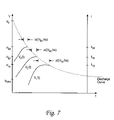
- FIGS. 1 , 6 and 7 graphically illustrate variation of a discharge hold off time ⁇ t(V;ho) with variation of an applied voltage V for several gas component ( FIG. 1 ) and for a single gas component ( FIGS. 6 and 7 ).
- FIGS. 2 and 4 schematically illustrate systems for practicing the invention.
- FIG. 3 graphically illustrates variation of a measurable electrical parameter with applied voltage V where two or more gas components are present.
- FIGS. 5A and 5B are a flow chart for practicing the invention.
- a gas detection system 21 using one or more carbon nanotubes (“CNTs”) 23 connected to a variable voltage plate 22 A, as anode, is spaced apart (d ⁇ 10-200 ⁇ m) from a grounded or other constant-voltage plate 22 B, as cathode.
- a gas G having an unknown composition and/or an unknown concentration is positioned in the anode-cathode gap.
- the variable voltage plate 22 A is connected to a variable voltage source 24 , and the constant voltage plate is maintained by a constant voltage source 25 (e.g., ground).
- Electrically insulating spacers 27 and/or 27 ′ are optionally positioned between adjacent electrically charged system components.
- a voltage (difference) V is increased in steps and held approximately constant at each of a discrete sequence of voltages until a gas discharge first occurs after a holdoff (ho) time interval ⁇ t(V ⁇ ;ho) after a threshold discharge voltage V ⁇ is established. Theoretically ⁇ t(V ⁇ ;ho) ⁇ .
- the voltage V is used to determine information on at least one gas component and/or on gas concentration in the gap, for one, two or more gas components.
- the voltage difference ⁇ V is further increased above the threshold V ⁇ , preferably in discrete steps, until a gas discharge occurs within a time interval of selected length (e.g., within 30 sec) after the (constant) voltage is established.
- the current will increase monotonically and approximately linearly with a characteristic slope b(n) until the (n+1)th threshold discharge voltage is reached, after which the measured current will increase approximately linearly (with a characteristic slope b(n+1)>b(n)) above V ⁇ (n+1), as illustrated in FIG. 3 .
- the slope b(n) of electrical current or cumulative electrical charge between any two consecutive holdoff voltages, V ⁇ (n) ⁇ V ⁇ V ⁇ (n+1), is determined experimentally for the contribution of two gas constituents (numbers n and n+1) corresponding to these holdoff voltages.
- Analogs of Eqs. (1)-(3) may also be applied to a measure of cumulative electrical charge e(V;n) for V ⁇ (n) ⁇ V ⁇ V ⁇ (n+1).
- the threshold discharge voltage value V ⁇ (n) for a single gas component may vary with concentration c(n) of the component no. n. Where only a single component is present in the gas G, V ⁇ may vary with concentration c(n), because a mean scattering distance for gas particles (proportional to nearest neighbor distance) will be approximately proportional to c(n) -1/3 .
- the system 41 shown schematically in FIG. 4 is similar to the system 21 in FIG. 2 , with the following changes.
- the variable voltage plate 22 A (in FIG. 2 ) is replaced by split voltage plates, 42 A- 1 and 42 A- 2 ;
- the constant voltage plate 22 B is optionally replaced by split constant voltage plates, 42 B- 1 and 42 B- 2 , having the same or different constant voltages sources, 45 - 1 (V 0 ′) and 45 - 2 (V 0 ′′); a different group of CNTs, 43 - 1 and 43 - 2 , is connected to the respective plates, 42 A- 1 and 42 A- 2 ;
- the variable voltage plate 24 is replaced by independently controlled variable voltage plates, 44 - 1 and 44 - 2 ;
- the meter 26 is optionally replaced by meters, 46 - 1 and 46 - 2 , connected to the respective plates 42 B- 1 and 42 B- 2 (or to the respective plates 42 A- 1 and 42 A- 2 ).
- the system 41 allows substantially simultaneous use of two or
- FIGS. 5A and 5B are a flow chart illustrating a basic procedure for practicing the invention.
- a first array of spaced apart carbon nanotubes (CNTs) is provided in a closed chamber, at least one CNT in the first array being attached at a first CNT end to a first variable voltage source and having a relatively sharp CNT tip at a second end of the at least one CNT, where the second end of the at least one CNT in the first array is spaced apart a distance d in a range 10-200 ⁇ m from a substantially constant voltage plate.
- Each CNT array preferably has a diameter of at least 20 ⁇ m, more preferably lying in a range of 20-50 ⁇ m.
- the array diameter may be as small as 1-5 ⁇ m, or smaller if desired. Any two CNT arrays are preferably spaced apart by a distance of at least 200 ⁇ m, more preferably at least 500 ⁇ m.
- a gas G having at least one unknown gas component and having a pressure in a range 10 ⁇ 3 ⁇ 760 Torr, is provided in the chamber, adjacent to the CNT second end.
- a first error sum of weighted magnitudes of difference values for example.
- step 57 determines if ⁇ 1 (k;p 1 ) is no greater than a threshold error number ⁇ 1 (k;thr), which may depend upon the index value k. If the answer to the query in step 57 is “yes,” the system notes, in step 58 , that the candidate gas component number k is (likely to be) present in the gas G, and moves to step 59 , where the counting index k is incremented (k—>k+1). If the answer to the query is step 57 is “no,” the system moves directly to step 59 .
- step 60 the system determines if the (incremented) index k is greater than the number K of candidate gas components. If the answer to the query in step 60 is “no,” the system returns to step 54 , and steps 54 - 60 are repeated. If the answer to the query in step 60 is “yes,” the system optionally reports that at least one of the candidate gas components, whose presence in the gas G was noted in step 58 , is (likely to be) present in the gas G, in step 61 . The process is optionally terminated in step 62 .
- a second error sum can be formed from weighted magnitudes of differences of the discharge holdoff times
- step 62 the procedure is preferably not terminated in step 62 .
- This approach is illustrated in FIG.
- V id increases, ⁇ t(V id ;ho) decreases and I id increases monotonically, but not necessarily strictly monotonically.
- the procedure is preferably not terminated in step 62 in FIG. 5B .
- V(meas;thr) is then replaced by the value V(new;meas;thr), and steps 54 - 66 in FIGS. 5A and 5B are reapplied to determine if another candidate gas component is likely to be present in the gas G.
- the CNT-based gas sensor disclosed here uses the sharp (low radius of curvature) tip(s) of one or more CNTs, preferably multiwall carbon nanotubes (“MWCNTs”) or carbon nanofibers (“CNFs”), to generate high strength electrical fields adjacent to the tip(s) for breakdown of gas components with lower voltage application and lower generation of high leakage current.
- the system and associated method can provide a high sensitivity, low power consumption tool that is very specific for identification of one or more gas components.
- a current meter can be multiplexed to measure the leakage current from each of two or more spaced apart CNT arrays, and the voltage delivered can be multiplexed to different CNT arrays to provide different discharge voltages to each array.
- the current measured in each sensing channel can be digitized to correlate with each of the components of a complex gas.
- the discharge gas sensor system disclosed here can identify one or more specific threshold discharge voltage values independently of the gas concentration.
- the gas sensor disclosed here can be operated at room temperature, or at any other reasonable temperature, and at any reasonable pressure, such as atmospheric pressure or moderately lower. Where the gas pressure in the chamber is p and the tip-to-constant voltage plate distance is d, the product pd will approximately characterize the pulse breakdown threshold voltage where d is no more than 1-3 mean free paths at the gas concentration provided.
Abstract
Description
I(V;n)=I{V ∞(n);n}b(n)·{V−V ∞(n)}p(V ∞(n)<V<V ∞(n+1)), (1)
with a choice p=p(n)≈1, illustrated graphically in
I(V;n)=I(V;n+1) at V V ∞(n+1), (2)
which provides an estimate for the threshold discharge voltage value V∞(n+1) and the corresponding initial current value I(V=V∞(n+1);n+1). The approach associated with Eq. (2) can also be used where the current in an intermediate voltage range is nonlinear in V, for example,
I(V;n)=I(V=V ∞(n);n) +b(n)·|V−V ∞(n)|q(n)(V ∞(n)≦V<V ∞(n+1)), (3)
where q(n) is an exponent having any positive value, which may vary with the index n. Analogs of Eqs. (1)-(3) may also be applied to a measure of cumulative electrical charge e(V;n) for V∞(n)≦V<V∞(n+1).
is computed, where wi and w∞ are non-negative weight coefficients and p1=p1(k) is a selected positive exponent number.
is computed, and the error sums ε1(k;p1(k)) and ε1(k) are replaced by ε2(k;p2(k)) and ε2(k), respectively, in steps 76 and 77, and a modified flow chart procedure is followed.
Claims (12)
Priority Applications (1)
| Application Number | Priority Date | Filing Date | Title |
|---|---|---|---|
| US11/203,589 US7529633B1 (en) | 2005-08-05 | 2005-08-05 | Application of carbon nanotube hold-off voltage for determining gas composition |
Applications Claiming Priority (1)
| Application Number | Priority Date | Filing Date | Title |
|---|---|---|---|
| US11/203,589 US7529633B1 (en) | 2005-08-05 | 2005-08-05 | Application of carbon nanotube hold-off voltage for determining gas composition |
Publications (1)
| Publication Number | Publication Date |
|---|---|
| US7529633B1 true US7529633B1 (en) | 2009-05-05 |
Family
ID=40584968
Family Applications (1)
| Application Number | Title | Priority Date | Filing Date |
|---|---|---|---|
| US11/203,589 Expired - Fee Related US7529633B1 (en) | 2005-08-05 | 2005-08-05 | Application of carbon nanotube hold-off voltage for determining gas composition |
Country Status (1)
| Country | Link |
|---|---|
| US (1) | US7529633B1 (en) |
Cited By (2)
| Publication number | Priority date | Publication date | Assignee | Title |
|---|---|---|---|---|
| US8783112B2 (en) | 2011-06-30 | 2014-07-22 | Caterpillar Inc. | Gas monitoring system implementing pressure detection |
| US8875560B2 (en) | 2011-06-30 | 2014-11-04 | Caterpillar Inc. | System implementing constituent identification and concentration detection |
Citations (3)
| Publication number | Priority date | Publication date | Assignee | Title |
|---|---|---|---|---|
| US6437329B1 (en) * | 1999-10-27 | 2002-08-20 | Advanced Micro Devices, Inc. | Use of carbon nanotubes as chemical sensors by incorporation of fluorescent molecules within the tube |
| US20060251543A1 (en) * | 2002-12-20 | 2006-11-09 | Rensselaer Polytechnic Institute | Miniaturized gas sensors featuring electrical breakdown in the vicinity of carbon nanotube tips |
| US7276266B1 (en) * | 2002-12-13 | 2007-10-02 | United States Of America As Represented By The Administrator Of The National Aeronautics And Space Administration (Nasa) | Functionalization of carbon nanotubes |
-
2005
- 2005-08-05 US US11/203,589 patent/US7529633B1/en not_active Expired - Fee Related
Patent Citations (3)
| Publication number | Priority date | Publication date | Assignee | Title |
|---|---|---|---|---|
| US6437329B1 (en) * | 1999-10-27 | 2002-08-20 | Advanced Micro Devices, Inc. | Use of carbon nanotubes as chemical sensors by incorporation of fluorescent molecules within the tube |
| US7276266B1 (en) * | 2002-12-13 | 2007-10-02 | United States Of America As Represented By The Administrator Of The National Aeronautics And Space Administration (Nasa) | Functionalization of carbon nanotubes |
| US20060251543A1 (en) * | 2002-12-20 | 2006-11-09 | Rensselaer Polytechnic Institute | Miniaturized gas sensors featuring electrical breakdown in the vicinity of carbon nanotube tips |
Non-Patent Citations (2)
| Title |
|---|
| Suehiro, et al., Detection of partial discharge in SF6 gas using a carbon nanotube-based gas sensor, Sensors and Actuators B, 2005, 164-169, 105, Elsevier B. V. |
| Zhang et al., "Study of gas sensor with carbon nanotube film on the substrate of porous silicon", Aug. 12-16, 2001, IEEE, Proceedings of the 14th Vacuum Microelectronics Conference, 2001. IVMC 2001, pp. 13-14. * |
Cited By (2)
| Publication number | Priority date | Publication date | Assignee | Title |
|---|---|---|---|---|
| US8783112B2 (en) | 2011-06-30 | 2014-07-22 | Caterpillar Inc. | Gas monitoring system implementing pressure detection |
| US8875560B2 (en) | 2011-06-30 | 2014-11-04 | Caterpillar Inc. | System implementing constituent identification and concentration detection |
Similar Documents
| Publication | Publication Date | Title |
|---|---|---|
| US7426848B1 (en) | Gas composition sensing using carbon nanotube arrays | |
| US6015484A (en) | Detection of pitting corrosion | |
| CN101339160B (en) | Plasma source ion synergic checking ion transfer spectrometer | |
| CN104251846A (en) | Discriminant analysis combined laser-induced breakdown spectroscopy quantitative analysis method | |
| Reimann et al. | Fire detection in coal mines based on semiconductor gas sensors | |
| US6457347B1 (en) | Glow discharge detector | |
| US7529633B1 (en) | Application of carbon nanotube hold-off voltage for determining gas composition | |
| Pobelov et al. | An approach to measure electromechanical properties of atomic and molecular junctions | |
| US7520975B2 (en) | Estimation of localised corrosion penetration | |
| CN113490321A (en) | Multi-Langmuir probe ionized layer electron density rapid detection method and application | |
| Pan et al. | A high-integration sensor array sensitive to oxynitride mixture | |
| Nighan et al. | Low energy electron collision phenomena in HgBr2 | |
| US20060232282A1 (en) | System and method for measuring conductivity on molecular level | |
| Mayhew et al. | Measurements of thermal electron attachment rate coefficients to molecules using an electron swarm technique | |
| CN102095791B (en) | Method for detecting concentration of two-component gas based on carbon nano tube film three-electrode sensor | |
| CN114460161B (en) | Trace substance detection method based on ion migration time | |
| CN100403022C (en) | Self-hold dark discharge carbon nanometer pipe film gas sensor and its gas concentration measuring method | |
| US4074572A (en) | Method and apparatus for sensing the flux of a flowing fluid | |
| Renninger et al. | Particle sizing by electrical single particle aerodynamic relaxation time analyzer | |
| CN109765334B (en) | Gas-liquid two-phase flow gas content measuring device and method in particle accumulation bed | |
| Goldman et al. | A repulsive‐field technique for obtaining the mobility‐spectra of the ion species created in a corona discharge | |
| Sullivan | Wheatstone bridge technique for magnetostriction measurements | |
| Richter et al. | Integrated high temperature gas sensor system based on bulk acoustic wave resonators | |
| CN103048522A (en) | Diagnosis method of low temperature plasma density parameter at atmospheric pressure | |
| US3542516A (en) | Flame ionization detection |
Legal Events
| Date | Code | Title | Description |
|---|---|---|---|
| AS | Assignment |
Owner name: USA AS REPRESENTED BY THE ADMINISTRATOR OF THE NAS Free format text: ASSIGNMENT OF ASSIGNORS INTEREST;ASSIGNOR:MEYYAPPAN, MEYYA;REEL/FRAME:018571/0701 Effective date: 20050805 Owner name: USA AS REPRESENTED BY THE ADMINISTRATOR OF THE NAS Free format text: ASSIGNMENT OF ASSIGNORS INTEREST;ASSIGNOR:LI, JING;REEL/FRAME:018571/0535 Effective date: 20050805 Owner name: USA AS REPRESENTED BY THE ADMINISTRATOR OF THE NAS Free format text: ASSIGNMENT OF ASSIGNORS INTEREST;ASSIGNOR:SCHIPPER, JOHN F.;REEL/FRAME:018571/0649 Effective date: 20050805 |
|
| AS | Assignment |
Owner name: USA AS REPRESENTED BY THE ADMINISTRATOR OF THE NAS Free format text: ASSIGNMENT OF ASSIGNORS INTEREST;ASSIGNOR:SCHIPPER, JOHN F.;REEL/FRAME:021848/0773 Effective date: 20081106 Owner name: USA AS REPRESENTED BY THE ADMINISTRATOR OF THE NAS Free format text: ASSIGNMENT OF ASSIGNORS INTEREST;ASSIGNOR:LI, JING;REEL/FRAME:021848/0757 Effective date: 20081106 |
|
| FPAY | Fee payment |
Year of fee payment: 4 |
|
| REMI | Maintenance fee reminder mailed | ||
| LAPS | Lapse for failure to pay maintenance fees | ||
| STCH | Information on status: patent discontinuation |
Free format text: PATENT EXPIRED DUE TO NONPAYMENT OF MAINTENANCE FEES UNDER 37 CFR 1.362 |
|
| FP | Lapsed due to failure to pay maintenance fee |
Effective date: 20170505 |
|
| FEPP | Fee payment procedure |
Free format text: PETITION RELATED TO MAINTENANCE FEES FILED (ORIGINAL EVENT CODE: PMFP) |
|
| FEPP | Fee payment procedure |
Free format text: PETITION RELATED TO MAINTENANCE FEES DISMISSED (ORIGINAL EVENT CODE: PMFS) |