US7522039B2 - Apparatus, method, and computer program for an alarm system - Google Patents

Apparatus, method, and computer program for an alarm system Download PDF

Info

Publication number
US7522039B2
US7522039B2 US11/981,729 US98172907A US7522039B2 US 7522039 B2 US7522039 B2 US 7522039B2 US 98172907 A US98172907 A US 98172907A US 7522039 B2 US7522039 B2 US 7522039B2
Authority
US
United States
Prior art keywords
signal
sensor
alarm
processor
controller
Prior art date
Legal status (The legal status is an assumption and is not a legal conclusion. Google has not performed a legal analysis and makes no representation as to the accuracy of the status listed.)
Expired - Lifetime
Application number
US11/981,729
Other versions
US20080088431A1 (en
Inventor
Sehat Sutardja
Hedley Rainnie
Eric Janofsky
Current Assignee (The listed assignees may be inaccurate. Google has not performed a legal analysis and makes no representation or warranty as to the accuracy of the list.)
Cavium International
Marvell Asia Pte Ltd
Original Assignee
Marvell International Ltd
Priority date (The priority date is an assumption and is not a legal conclusion. Google has not performed a legal analysis and makes no representation as to the accuracy of the date listed.)
Filing date
Publication date
Priority claimed from US10/184,302 external-priority patent/US7457676B1/en
Priority claimed from US10/184,505 external-priority patent/US7546172B1/en
Priority claimed from US10/184,299 external-priority patent/US7315764B1/en
Application filed by Marvell International Ltd filed Critical Marvell International Ltd
Priority to US11/981,729 priority Critical patent/US7522039B2/en
Publication of US20080088431A1 publication Critical patent/US20080088431A1/en
Application granted granted Critical
Publication of US7522039B2 publication Critical patent/US7522039B2/en
Assigned to CAVIUM INTERNATIONAL reassignment CAVIUM INTERNATIONAL ASSIGNMENT OF ASSIGNORS INTEREST (SEE DOCUMENT FOR DETAILS). Assignors: MARVELL INTERNATIONAL LTD.
Assigned to MARVELL ASIA PTE, LTD. reassignment MARVELL ASIA PTE, LTD. ASSIGNMENT OF ASSIGNORS INTEREST (SEE DOCUMENT FOR DETAILS). Assignors: CAVIUM INTERNATIONAL
Anticipated expiration legal-status Critical
Expired - Lifetime legal-status Critical Current

Links

Images

Classifications

    • AHUMAN NECESSITIES
    • A01AGRICULTURE; FORESTRY; ANIMAL HUSBANDRY; HUNTING; TRAPPING; FISHING
    • A01GHORTICULTURE; CULTIVATION OF VEGETABLES, FLOWERS, RICE, FRUIT, VINES, HOPS OR SEAWEED; FORESTRY; WATERING
    • A01G25/00Watering gardens, fields, sports grounds or the like
    • A01G25/16Control of watering
    • GPHYSICS
    • G08SIGNALLING
    • G08BSIGNALLING OR CALLING SYSTEMS; ORDER TELEGRAPHS; ALARM SYSTEMS
    • G08B25/00Alarm systems in which the location of the alarm condition is signalled to a central station, e.g. fire or police telegraphic systems
    • G08B25/01Alarm systems in which the location of the alarm condition is signalled to a central station, e.g. fire or police telegraphic systems characterised by the transmission medium
    • G08B25/10Alarm systems in which the location of the alarm condition is signalled to a central station, e.g. fire or police telegraphic systems characterised by the transmission medium using wireless transmission systems
    • GPHYSICS
    • G05CONTROLLING; REGULATING
    • G05BCONTROL OR REGULATING SYSTEMS IN GENERAL; FUNCTIONAL ELEMENTS OF SUCH SYSTEMS; MONITORING OR TESTING ARRANGEMENTS FOR SUCH SYSTEMS OR ELEMENTS
    • G05B2219/00Program-control systems
    • G05B2219/20Pc systems
    • G05B2219/26Pc applications
    • G05B2219/2625Sprinkler, irrigation, watering

Definitions

  • the present invention relates generally to alarm systems.
  • FIG. 1 is an example of a conventional MP3 player.
  • MP3 player includes an interface 106 , nonvolatile solid state memory 102 , a decoder 110 , a digital-to-analog (D/A) converter 147 , an audio output 116 , a key pad 108 , a display 112 , a controller 104 , RAM 144 and ROM 145 .
  • D/A digital-to-analog
  • Controller 104 controls the operation of the MP3 player in accordance with a set of programmed instructions.
  • Programmed instructions for controller 104 are stored in nonvolatile memory or ROM 145 , and RAM 144 is provided as the working memory for controller 104
  • MP3 data which is a digital compressed format representing music data
  • the MP3 data is stored in nonvolatile solid state memory 102 .
  • Interface 50 can implemented by a standard parallel port, serial port, USB and the like.
  • Nonvolatile solid state memory 102 may be implemented as flash memory.
  • flash memory Generally, for a music quality recording, a nonvolatile solid state memory having 64 Mbytes can store about 1 hour of music. Flash memory provides the capability of retaining the stored digital data even when the MP3 player is powered down. Once the digital data has been transferred to the MP3 player, it no longer needs to be connected to personal computer 50 , and the MP3 player can play back the MP3 data autonomously from personal computer 50 .
  • Decoder 110 functions to decode and decompress the MP3 data file stored in nonvolatile solid state memory 102 . Decoder 110 decompresses the MP3 music file in accordance controller 104 according to the MP3 format, and decodes the decompressed music file into a bit stream form. The bit stream is then converted into analog form by digital to analog converter 147 for connection to a speaker, earphone and the like. A decoding program for the MP3 decoder function is stored in the ROM 145 and loaded to RAM 144 by controller 104 as required.
  • the MP3 player comprises a keypad 108 for allowing user control and interaction with the MP3 player. Such control may include power on/power off, music selection and volume.
  • the MP3 also comprises a display 112 for displaying characters or graphics, such as a battery indicator, a play mode indicator, a volume indicator, available memory size and the title of the music being played.
  • the invention features a method, apparatus, and computer program for an alarm system. It comprises a master unit; and an alarm monitor comprising an alarm sensor to provide a sensor signal representing alarm conditions; a processor to produce digital data based on the alarm signal; and a media access controller to generate a report signal comprising the digital data; and a transmitter to transmit the report signal to the master unit.
  • the processor is further to cause the transmitter to transmit the report signal when the sensor signal meets a predetermined condition.
  • the alarm sensor comprises a camera; and the sensor signal comprises an image captured by the camera.
  • the media access controller is further to generate a packet comprising the digital data; and the transmitter is further to transmit the packet.
  • the media access controller is further to generate an electronic mail message comprising the digital data; and the transmitter is further to transmit the electronic mail message.
  • the alarm monitor further comprises a receiver to receive a further signal comprising a destination address; wherein the media access controller directs the electronic mail message to the destination address.
  • the processor is further to enter a sleep mode when the sensor signal meets a predetermined condition for a predetermined interval; and, when the sensor signal no longer meets the predetermined condition, the processor is further to leave the sleep mode and to cause the transmitter to transmit the report signal.
  • the alarm sensor comprises at least one of the group comprising a seismometer; a barometer; a thermometer; a motion detector; a smoke detector; a carbon monoxide detector; and a glass breakage detector. Implementations comprise a receiver to receive a further signal representing sensor calibration information from the master unit; wherein the media access controller is further to obtain the sensor calibration information from the further signal; and wherein the processor is further to calibrate the alarm sensor in accordance with the sensor calibration information.
  • the alarm system complies with a standard selected from the group consisting of IEEE 802.11; IEEE 802.11a; IEEE 802.11b; IEEE 802.11g; IEEE 802.11h; and IEEE 802.11i.
  • the processor and the media access controller are implemented together as a single integrated circuit.
  • the alarm sensor, the processor and the media access controller are implemented together as a single integrated circuit.
  • the invention features a method, apparatus, and computer program for an alarm system. It comprises receiving a signal representing digital data; obtaining the digital data from the signal representing the digital data; and producing a control signal based on the digital data; and providing the control signal to an actuator to manipulate a physical portal in response to the control signal.
  • Manipulating the physical portal is selected from the group consisting of opening the physical portal; closing the physical portal; locking the physical portal; and obscuring the physical portal.
  • the physical portal is selected from the group consisting of a window; and a door. It comprises receiving a sensor signal provided by one or more sensors; and providing the control signal based on the digital data and the sensor signal.
  • the one or more sensors comprise at least one of the group comprising a thermometer; a light detector; a moisture detector; a wind detector; a barometer; a motion detector; a smoke detector; a gas detector; and a glass breakage detector.
  • It comprises providing a keypad control signal in response to operation of a keypad; and providing the control signal based on the digital data and the keypad control signal. It comprises displaying a status of the apparatus. It comprises transmitting a report signal representing a status of the apparatus. It comprises storing an actuator schedule; and producing the control signal based on the actuator schedule. It comprises producing the control signal based on the actuator schedule when the signal representing the digital data is unavailable.
  • the invention features a physical portal comprising a processor to produce digital data based on a sensor signal provided by a sensor; a media access controller to generate a report signal comprising the digital data; and a transmitter to transmit the report signal.
  • the physical portal is selected from the group consisting of a window; and a door.
  • the processor is further to cause the transmitter to transmit the report signal when the sensor signal meets a predetermined condition.
  • the sensor comprises a camera; and wherein the sensor signal comprises an image captured by the camera.
  • the media access controller is further to generate a packet comprising the digital data; and wherein the transmitter is further to transmit the packet.
  • the media access controller is further to generate an electronic mail message comprising the digital data; and wherein the transmitter is further to transmit the electronic mail message.
  • the physical portal further comprises a receiver to receive a further signal comprising a destination address; wherein the media access controller directs the electronic mail message to the destination address.
  • the processor is further to enter a sleep mode when the sensor signal meets a predetermined condition for a predetermined interval; and wherein, when the sensor signal no longer meets the predetermined condition, the processor is further to leave the sleep mode and to cause the transmitter to transmit the report signal.
  • the physical portal further comprises the sensor.
  • the sensor comprises at least one of the group comprising a thermometer; a light detector; a moisture detector; a wind detector; a barometer; a motion detector; a smoke detector; a gas detector; and a glass breakage detector.
  • the sensor, the processor and the media access controller are implemented together as a single integrated circuit.
  • the physical portal further comprises a receiver to receive a further signal representing sensor calibration information; wherein the media access controller is further to obtain the sensor calibration information from the further signal; and wherein the processor is further to calibrate the sensor in accordance with the sensor calibration information.
  • the transmitter complies with a standard selected from the group consisting of IEEE 802.11; IEEE 802.11a; IEEE 802.11b; IEEE 802.11g; IEEE 802.11h; and IEEE 802.11i.
  • the processor and the media access controller are implemented together as a single integrated circuit.
  • the physical portal further comprises a receiver to receive a signal representing digital data; wherein the media access controller is further to obtain the digital data from the signal representing the digital data; wherein the processor is further to produce a control signal based on the digital data obtained by the media access controller; and an output circuit to provide the control signal to an actuator to manipulate the physical portal in response to the control signal.
  • the physical portal further comprises the actuator.
  • the actuator is selected from the group consisting of a device to open the physical portal; a device to close the physical portal; a device to lock the physical portal; and a device to obscure the physical portal.
  • the processor is further to provide the control signal based on the digital data obtained by the media access controller and the sensor signal.
  • the physical portal further comprises a keypad to provide a keypad control signal in response to operation of the keypad; wherein the processor is further to provide the control signal based on the digital data obtained by the media access controller and the keypad control signal.
  • the physical portal further comprises a display to display a status of the physical portal.
  • the receiver is a wireless receiver. The receiver complies with a standard selected from the group consisting of IEEE 802.11; IEEE 802.11a; IEEE 802.11b; IEEE 802.11g; IEEE 802.11h; and IEEE 802.11i.
  • the physical portal further comprises a memory to store an actuator schedule; and wherein the processor is further to produce the control signal based on the actuator schedule.
  • the processor is further to produce the control signal based on the actuator schedule stored in the memory when the signal representing the digital data is unavailable.
  • the memory is non-volatile.
  • FIG. 1 is a block diagram of a conventional MP3 player.
  • FIG. 2 is a block diagram of a first embodiment of a media player/recorder in accordance with the present invention.
  • FIG. 3 is a more detailed block diagram of a first embodiment of the media player/recorder of FIG. 2 .
  • FIG. 4 is a block diagram of a second embodiment of a media player/recorder in accordance with the present invention.
  • FIG. 5 is a more detailed block diagram of the media player/recorder of FIG. 4 .
  • FIG. 6 shows an exemplary data format of a magnetic disk having a plurality of concentric tracks comprised of a plurality of user data sectors and embedded servo data sectors.
  • FIG. 7 is a schematic representation of memory 202 .
  • FIG. 8 is a memory map of memory 202 .
  • FIG. 9 is flow chart of an energization/deenergization procedure according to a first embodiment of the present invention.
  • FIG. 10 is flow chart of an energization/deenergization procedure according to a second embodiment of the present invention.
  • FIG. 11 is flow chart of an energization/deenergization procedure according to a third embodiment of the present invention.
  • FIG. 12 is flow chart of an operating procedure according to the present invention.
  • FIG. 13 shows a variation of the first embodiment of the media player/recorder of FIG. 2 .
  • FIG. 14 shows a variation of the second embodiment of the media player/recorder of FIG. 2 .
  • FIG. 15 is a block diagram of a third embodiment of a media player/recorder in accordance with the present invention.
  • FIG. 16 is a block diagram of a fourth embodiment of a media player/recorder in accordance with the present invention.
  • FIG. 17 illustrates a mode of some implementations referred to as “local radio mode.”
  • FIG. 18 shows an implementation where a media player/recorder is implemented within a digital camera.
  • FIG. 19 shows automobiles equipped with a media player/recorder in accordance with the present invention.
  • FIG. 20 shows an implementation where a media player/recorder communicates with a biometric sensor over a cable.
  • FIG. 21 show a biometric sensor worn on a finger and transmitting biometric data over a cable.
  • FIG. 22 shows a process for a media player/recorder to acquire shared media.
  • FIG. 23 shows a process for a media player/recorder to share media.
  • FIG. 24 shows a process for a media player/recorder to match items of interest.
  • FIG. 25 shows an alarm system according to an embodiment of the present invention.
  • FIG. 26 shows a controller according to an embodiment of the present invention.
  • FIG. 27 shows a process that can be performed by the controller of FIG. 26 according to a preferred embodiment.
  • FIG. 28 shows a window according to one embodiment.
  • FIG. 29 shows a process that can be performed by the window of FIG. 28 according to one embodiment.
  • Embodiments of the present invention are directed to an alarm system that transmits digital data representing alarm conditions such as weather conditions, motion, gas content, sounds, and so on.
  • the digital data can be encoded, compressed or both, and can be transmitted wirelessly or by wire, cable, or the like.
  • the media player/recorder includes a wired interface 206 , a wireless interface 210 , memory 202 , a processor 300 , an output 216 , a keypad 208 , a display 212 , a storage device (the storage device may utilize, for example, a magnetic media (such as a hard disk drive), magneto-optical media, an optical media (such as a CD ROM, CDR, CDRW or the like), and the like) such as, a disk drive 230 , a preamp 232 and a voice coil motor (VCM) 234 .
  • Wireless interface 210 includes a wireless transmitter 209 and a wireless receiver 211 .
  • the operation of the media player/recorder is as follows. Operation of the media player/recorder is controlled by the user through keypad 208 . Status of the media player/recorder is provided to the user by display 212 .
  • Media data which was previously digitized, may be obtained (downloaded) from a personal computer, network appliance, local area network, Internet 50 and the like, including wireless networks with infrastructure, such as a designated access point, peer-to-peer wireless networks, and the like.
  • Such external devices communicate with the media player/recorder via wired interface 206 and wireless interface 210 , which are controlled by processor 300 .
  • Wired interface 206 may be implemented, for example, as a parallel interface, serial interface, USB, Ethernet connection, IEEE 1394 (a.k.a. Firewire), and the like.
  • Wireless interface 210 may be implemented, for example, as an infrared interface, IEEE 802.15, IEEE 802.11, BluetoothTM and the like. Again the present invention is independent of the interface selected.
  • Disk drive 230 is preferably a miniature drive with a capacity of 1 Gbyte of data storage, which is particularly suitable for a portable device. Of course, any other appropriate sized disk drive may be employed.
  • media data may be obtained directly from an external analog source, such as a microphone or video camera, connected to input 214 .
  • Input 214 takes the input signal from external device and sets the analog signal to an appropriate level.
  • the analog signal is then converted to a digital signal and compressed using a selected format by processor 300 , as will be described herein below.
  • the compressed digital data is similarly stored on disk drive 230 .
  • processor 300 When the user chooses a selection of media data to be played back with keypad 208 , processor 300 powers up disk drive 230 and retrieves the selected data which is then transferred to memory 202 . It is noted that the powering up of the device is done in a sequential manner so as to minimize energy consumption of the device. A more detailed description is provided below.
  • Memory 202 comprises a solid state memory, such as, for example dynamic random access memory (solid state memory), flash memory, EEPROM, or the like. It is not necessary for memory 202 to be nonvolatile since the media data is stored in a nonvolatile manner on storage device or disk drive 230 .
  • the quantity of solid state memory required is less than is required in a conventional MP3 player.
  • the quantity of solid state memory contemplate is about 2 Mbytes, which is sufficient to store about 2 minutes of MP3 data. Of course, as will be appreciated by one of ordinary skill in the art, when dealing with video data, more solid state memory may be required.
  • the amount of solid state memory supplied is selected to minimize energy consumption.
  • disk drive 230 is then powered down. In this manner, during playback disk drive 230 is powered up only during the transfer of the selected media data from disk drive 230 to memory 202 , which results in lower energy consumption. A more detailed description of the powering down of disk drive 230 is provided herein below.
  • the media data is retrieved from memory 202 .
  • Processor 300 determines the format of data compression from the retrieved data.
  • Disk drive 230 also stores the data compression/decompression algorithms.
  • the data is decompressed in accordance with the determined format and converted to an analog signal by processor 300 .
  • the analog signal is set to an appropriate level by output circuit 216 . If the analog signal contains audio data, output circuit 216 is connected to a speaker, headphone and the like for playback, and if the analog signal contains video data, output circuit 216 is connected to a display device for playback.
  • media data recorded on disk drive 230 or stored in memory 202 may be transferred (uploaded) to a personal computer, network appliance, local area network, internet 50 or another media player/recorder through interfaces 206 and 210 under the control of processor 300 .
  • FIG. 3 is a detailed block diagram of processor 300 .
  • Processor 300 is preferably implemented as a single integrated circuit.
  • a media playback/recorder apparatus having a processor implemented as a single integrated circuit can be fabricated at lower cost and have lower energy consumption.
  • processor 300 may be implemented by discrete components.
  • Processor 300 comprises a read channel 341 , storage controller or hard disk controller 342 , digital signal processor/microprocessor unit (DSP/MPU) 343 , random access memory (RAM) 344 , a non volatile memory such as read only memory (ROM) 345 , digital to analog converter (DAC) 346 and analog to digital converter (ADC) 347 .
  • DSP/MPU 343 comprises servo controller 349 and Codec 348 .
  • DSP/MPU 343 is implemented as a single integrated circuit.
  • MPU may be implemented as one integrated circuit and the DSP may be implemented as another integrated circuit.
  • DSP/MPU 343 may comprise a microprocessor unit, a digital signal processor, or any combination thereof.
  • ROM 345 stores programmed instructions for processor 300 and DSP/MPU 343 to control the operation of both the disk drive 230 (and associated circuitry) and the signal processing of the media data.
  • RAM 345 is provided as a working memory for DSP/MPU 343 .
  • the decompression and compression algorithms for Codec 348 are stored on disk drive 230 . Storing the decompression and compression algorithms on disk drive 230 minimizes the size of ROM 345 and its energy consumption. Additionally, this feature allows future compression and decompressions formats to be easily implemented for the media player/recorder.
  • wireless interface 210 is implemented separately from processor 300 , and includes an antenna 356 , a wireless unit 354 , a baseband processor 352 , and a media access controller (MAC) 350 .
  • Antenna 356 is a conventional antenna for receiving and transmitting wireless signals.
  • Wireless unit 354 converts wireless signals received by antenna 356 to analog baseband signals, and converts analog baseband signals received from baseband processor 352 to wireless signals for transmission by antenna 356 .
  • Baseband processor 352 converts analog baseband signals received from wireless unit 354 to a digital bitstream, and converts a digital bitstream received from MAC 350 to analog baseband signals, both according to well-known methods.
  • MAC 350 frames the digital bitstream produced by baseband processor 352 , and filters the frames to select the frames addressed to processor 300 , both according to well-known methods. MAC 350 also converts frames received from processor 300 to a digital bitstream for baseband processor 352 , also according to well-known methods. In some implementations, MAC 350 includes an embedded microprocessor.
  • FIG. 6 shows an exemplary data format of a magnetic media used in disk drive 230 , comprising a series of concentric data tracks 13 wherein each data track 13 comprises a plurality of sectors 15 with embedded servo wedges 17 .
  • Servo controller 349 processes the servo data in servo wedges 17 and, in response thereto, positions the read/write head over a desired track. Additionally, servo controller 349 processes servo bursts within servo wedges 17 to keep a disk head of disk drive 230 aligned over a centerline of the desired track while writing and reading data.
  • Servo wedges 17 may be detected by the discrete time sequence detector implemented in DSP/MPU 343 . It is important to note that DSP/MPU 343 is utilized only during the time period for detecting servo wedges 17 ; during other periods DSP/MPU 343 is available to perform other functions as described below, such as signal processing for media data playback and recording. By using only one DSP rather than two, the cost of fabrication and the amount of energy consumption can be reduced.
  • the powering up of the device is done in a sequential manner so as to minimize energy consumption of the device. More specifically, the mechanical or motor portions of the storage device are energized first. After the motor reaches operating speed, VCM 234 is energized, followed by the energization of read channel 341 and HDC 342 .
  • DSP/MPU 343 controls the entire operation of the media player/recorder.
  • DSP/MPU 343 is coupled to hard disk controller 342 .
  • hard disk controller 342 receives a write instruction and write data from DSP/MPU 343 .
  • the write data is temporarily stored in a cache memory (not shown) which is used as a buffer memory.
  • DSP/MPU 343 controls voice coil motor (VCM) and spindle motor 234 via servo unit 349 .
  • VCM voice coil motor
  • the magnetic head is moved to a desired track position on the magnetic disk by the head arm, and the magnetic disk is rotated at a rated rotational speed by the spindle, which is driven by spindle motor 234 .
  • the data is read from the cache memory and supplied to read channel 341 via hard disk controller 342 .
  • Read channel 341 encodes the write data under the control of DSP/MPU 343 , and supplies the encoded write data to preamplifier 232 .
  • the magnetic head writes the encoded write data on the magnetic disk in accordance with a signal from preamplifier 232 .
  • hard disk controller 342 When reading data from the magnetic disk, hard disk controller 342 receives a read instruction from DSP/MPU 343 . Based on a clock signal, DSP/MPU 343 controls voice coil motor and spindle motor 234 via servo unit 349 . Hence, the magnetic head is moved to a desired track position on the magnetic disk by the head arm, and the magnetic disk is rotated by spindle motor 234 .
  • the data read from the magnetic disk by the magnetic head is supplied to read channel 341 via preamplifier 232 .
  • Read channel 341 decodes the read data under the control of DSP/MPU 343 , and generates read data.
  • the read data are supplied from read channel 341 to hard disk controller 342 under the control of DSP/MPU 343 , and are temporarily stored in the cache memory.
  • the read data read from the cache memory are supplied to DSP/MPU 343 from hard disk controller 342 .
  • operation of the media player/recorder is controlled by the user through keypad 208 , which is in communication with DSP/MPU 343 .
  • Status of the media player/recorder is provided to the user by display 212 in accordance with DSP/MPU 343 .
  • the media player/recorder is in communication with personal computer, network appliance, local area network, Internet 50 . Otherwise the media player/recorder can be operated independently.
  • the user selects the file to be downloaded from personal computer, network appliance, local area network, Internet 50 by way of keypad 208 .
  • the user can select the file to be downloaded from the personal computer.
  • DSP/MPU 343 controls the flow of data through interfaces 206 and/or 210 and stores the data onto hard disk 230 in accordance with the method described above. When uploading data to personal computer, network appliance, local area network, Internet 50 the process is reversed.
  • the external device To record data directly input into media player/recorder from an external analog source, the external device is placed in communication with input 214 .
  • Input 214 takes the input signal from the external device and sets the analog signal to an appropriate level.
  • the analog signal is then converted to a digital signal by ADC 347 of processor 300 .
  • Codec 348 of DSP/MPU 343 compresses the digitized data using a default compression format or one selected by the user by way of keypad 208 .
  • the default or selected compression program is transferred from hard disk 230 to RAM 344 and provided to Codec 348 for encoding.
  • the compressed digital data is similarly stored on disk drive 230 under the control of DSP/MPU 343 .
  • DSP/MPU 343 powers up disk drive 230 and retrieves the selected data as described above. The retrieved data is then written to memory 202 . After the selected data is stored in memory 202 , disk drive 230 is then powered down by DSP/MPU 343 . In this manner, during playback disk drive 230 is powered up only during the transfer of the selected media data from disk drive 230 to memory 202 , which results in lower energy consumption. A single song stored in MP3 format may take approximately one second to retrieve from disk drive 230 . The media data is retrieved from memory 202 by DSP/MPU 343 and the compression format is then determined.
  • the decompression program If the decompression program has already been transferred to RAM 344 , the program is provided to Codec 348 . Otherwise the decompression algorithm is retrieved from hard disk 230 and transferred to RAM 344 . The data is then decompressed by Codec 348 and converted to an analog signal by DAC 346 . The analog signal is set to an appropriate level by output circuit 216 . If the analog signal contains audio data, output circuit 216 is connected to a speaker, headphone and the like for playback, and if the analog signal contains video data, output circuit 216 is connected to a display device for playback.
  • disk drive 230 is selected to hold a desired amount of media data, and the amount of solid state memory 202 is selected to minimize energy consumption.
  • a disk drive having a capacity of 1 Gbyte can store approximately 30 hours of MP3 compressed music.
  • the various components of media player are powered up in a sequential manner so as to minimize energy consumption of the device. More specifically, the mechanical or motor portions of the storage device or disk drive 230 are energized first (step 914 ). After the motor reaches its operating speed (step 916 ), VCM 234 , preamp 232 , read channel 341 and HDC 342 are energized, since these components are only functional after disk drive 230 becomes operational. Energy would be unnecessarily expended if preamp 232 , read channel 341 and HDC 342 were energized before disk drive 230 becomes operational.
  • VCM 234 , preamp 232 , read channel 341 and HDC 342 are energized only after disk drive 230 becomes operational (step 918 ).
  • Preamp 232 , read channel 341 and HDC 342 can be referred to as a storage circuit and include circuits to transform data stored on a storage device to a digital signal.
  • FIG. 7 is a schematic representation of memory 202 .
  • User data is first stored from location 724 to location 702 in a sequential manner in memory 202 .
  • DSP/MPU 343 uses a pointer system in connection with memory 202 to determine when the amount of data stored the amount data stored reaches an upper threshold value (step 922 ).
  • HDC 342 , read channel 341 , preamp 232 , disk drive 230 and VCM 234 are powered down or deenergized (step 924 ).
  • data may also be read contemporaneously therefrom by DSP/MPU 343 for decompression and playback.
  • Data is then read out from memory 202 starting at location 702 towards location 724 by DSP/MPU 343 (step 926 ).
  • the user can select another file.
  • the data is continually read from memory 202 , until the amount of data remaining is below a low threshold value (step 930 ).
  • disk drive 230 When the data remaining in memory 202 is below the threshold value, disk drive 230 , VCM 234 , preamp 232 , read channel 341 and HDC 342 are sequentially energized as noted above, and data is transferred from the storage device to memory 202 .
  • FIG. 10 is an alternate embodiment to FIG. 9 .
  • the amount of data transferred to memory 202 is counted (step 1020 ) by a counter incorporated in DSP/MPU 343 .
  • the sequential energization of the disk drive 230 , VCM 234 , preamp 232 , read channel 341 and HDC 342 is similar to that of the embodiment of FIG. 9 (steps 1012 , 1014 , 1016 and 1018 ).
  • step 1022 HDC 342 , read channel 341 , preamp 232 , disk drive 230 and VCM 234 are powered down or deenergized (step 1024 ).
  • the counter decrements the count, and when the count is less than or equal to a lower limit 1 (step 1030 ), disk drive 230 , VCM 234 , preamp 232 , read channel 341 and HDC 342 are sequentially energized as noted above, and data is transferred from the storage device to memory 202 .
  • FIG. 11 is another alternate embodiment to FIG. 9 .
  • the embodiment in FIG. 9 utilizes a timer incorporated in DSP/MPU 343 to approximate the amount of data transferred to memory 202 in accordance with the data transfer rate of disk drive 230 .
  • the sequential energization of disk drive 230 , VCM 234 , preamp 232 , read channel 341 and HDC 342 is similar to that of the embodiment of FIG. 9 (steps 1112 , 1114 , 1116 and 1118 ).
  • the timer is started (step 1119 ) as data is transferred form disk drive 230 to memory 202 .
  • HDC 342 , read channel 341 , preamp 232 , disk drive 230 and VCM 234 are powered down or deenergized (step 1124 ).
  • the timer is started ( 1125 ), and when the timer times out (step 1130 ), disk drive 230 , VCM 234 , preamp 232 , read channel 341 and HDC 342 are sequentially energized as noted above, and data is transferred from the storage device to memory 202 .
  • media data representing one selection is transferred from disk drive 230 to memory 202 for playback.
  • FIG. 8 is a schematic representation of memory 202
  • FIG. 12 is a flow chart illustrating an alternate implementation.
  • first portions of multiple selections are transferred from disk drive 230 to memory 202 .
  • These multiple selections may include the user's favorite selections, random selections from an external source, or the like (step 1204 ).
  • a timer is started (step 1208 ) and the first selection is played back (step 1210 ).
  • step 1212 If a user instruction is received (step 1212 ) to continue playing that selection is received within a predetermined time (step 1214 ), the remaining portion of the selection is transferred from disk drive 230 to memory 202 (step 1216 ) for continued play back (step 1218 ). If the timer times out (step 1214 ), the first portion of the next selection (step 1206 ) is played back and the process is repeated for each remaining first portion.
  • a memory threshold as shown in FIG. 8 , may be utilized permit playback of the entire current selection if the user instruction is received before the memory being read out goes below the current selection threshold. Otherwise the first portion of the next selection is played back.
  • the play back of portions of selections 1 through N may be in any order, such as sequential, random and predetermined. If the play back is in sequential order new selections may be transferred from disk drive 230 to memory 202 to replace previously played back selections.
  • FIGS. 4 and 5 show a second embodiment of the present invention.
  • the second embodiment is similar to the first embodiment except the second embodiment does not include memory 202 .
  • media data is recorded in a similar manner as the first embodiment and no further discussion is provided herein.
  • the media data is retrieved directly from disk drive 230 for playback through output 216 .
  • the other portions of the playback operation are similar to the first embodiment.
  • disk drive 230 will be powered on any time media data is recorded or played back.
  • the media player/recorder of the second embodiment may be a portable device used in an automobile supply by energy therefrom.
  • MAC 350 includes an embedded microprocessor.
  • FIG. 13 shows a variation of the first embodiment.
  • baseband processor 352 and MAC 350 are implemented within processor 300 , preferably as a single integrated circuit.
  • Wireless interface 210 includes antenna 356 and wireless unit 354 .
  • This variation operates as described for the first embodiment.
  • MAC 350 includes an embedded microprocessor.
  • FIG. 14 shows a variation of the second embodiment.
  • baseband processor 352 and MAC 350 are implemented within processor 300 , preferably as a single integrated circuit.
  • Wireless interface 210 includes antenna 356 and wireless unit 354 .
  • This variation operates as described for the first embodiment.
  • MAC 350 includes an embedded microprocessor.
  • FIG. 15 is a block diagram of a third embodiment of a media player/recorder in accordance with the present invention.
  • a MAC 1550 is implemented within processor 300 , which is preferably implemented as a single integrated circuit, and includes an embedded digital signal processor and microprocessor unit (DSP/MPU) 1551 .
  • DSP/MPU 1551 includes codec 348 , and communicates with memory 202 , display 212 , keypad 208 , wired interface 206 , RAM 344 , DAC 346 , and ADC 347 , which function as described above with reference to FIG. 3 .
  • DSP/MPU 343 has been replaces with DSP/MPU 1543 , which controls disk drive 230 , read channel 341 , and HDC 342 as described above.
  • FIG. 16 is a block diagram of a fourth embodiment of a media player/recorder in accordance with the present invention.
  • This embodiment is similar to the above embodiments, but has no hard drive.
  • Some implementations of this embodiment optionally include a non-volatile memory 1602 such as a flash memory instead of a hard drive. Consequently the circuits associated with the hard drive are also eliminated, resulting in a less-expensive media player/recorder.
  • baseband processor 352 and MAC 350 are implemented within processor 300 , which is preferably implemented as a single integrated circuit.
  • baseband processor 352 and MAC 350 are implemented separately from processor 300 , for example, within wireless interface 210 .
  • MAC 350 includes an embedded DSP/MPU. These implementations operate in a manner similar to that described for the implementations of FIG. 15 .
  • non-volatile memory instead of a hard drive are especially useful for receiving streaming media from broadcasts such as internet radio stations and other media player recorders.
  • Some implementations feature a “broadcast” mode where the media player/recorder plays a media selection and wirelessly transmits the media selection, either compressed or uncompressed, or in analog form, such that other media player/recorders can receive the broadcast media and play it at the same time as the broadcasting player/recorder.
  • FIG. 17 illustrates the local radio mode.
  • the media is wirelessly streamed to the media player/recorder 1704 , which decompresses and plays the media without storing the media.
  • the media player/recorder never stores a copy of the media, it is ideal for playing media for which only a single copy is licensed.
  • the single copy is stored on a personal computer (PC) 1702 , and is streamed to media player/recorder 1704 for playback. Because only a single copy of the media is stored, the single-copy license is satisfied.
  • PC personal computer
  • FIG. 18 shows an implementation where a media player/recorder 1804 is implemented within a digital camera 1802 .
  • an image sensor 1806 within camera 1802 captures one or more images, and passes a signal representing the image to media player/recorder 1804 .
  • a signal representing the image to media player/recorder 1804 .
  • a digital signal processor within media player/recorder 1804 then encodes the digital signal.
  • the encoding can include image compression, image manipulation, and the like.
  • a storage controller within media player/recorder 1804 stores the encoded image data on a storage device.
  • digital camera 1802 is a digital motion picture camera and the encoded image data represents a motion picture.
  • the storage controller retrieves the encoded image data from the storage device.
  • the digital signal processor decodes the retrieved encoded image data.
  • Media player/recorder 1804 sends a signal representing the decoded image data to a display 1808 , which displays the image(s) captured by image sensor 1806 .
  • a The media player/recorder described herein can be implemented as a portable unit, as a permanently mounted unit within a vehicle such as an automobile, and the like.
  • FIG. 19 shows automobiles 1902 A and 1902 B equipped with such a media player/recorder.
  • the antenna of the automobile can serve as the antenna of the media player/recorder.
  • the media player/recorders in the automobiles 1902 can communicate with each other, without user intervention, while traveling near each other, while stopped at intersections, and in other similar scenarios, to share media data, items of interest, and the like.
  • the media player/recorders in the automobiles 1902 can also communicate with portable media player/recorders 1904 in a similar fashion.
  • the vehicular and portable media player/recorders can communicate with a stationary base station 1906 to share media over a network such as the Internet.
  • a homeowner can equip his garage with such a base station 1906 so the media player/recorder in his automobile can share media and items of interest while parked in the garage during the night.
  • a user of a portable player/recorder 1904 can equip his home with a base station 1906 so the media player/recorder 1904 can share media and items of interest while not otherwise in use, for example while the user sleeps.
  • Some implementations receive and store data other than media data.
  • the media player/recorder records biometric data collected by a biometric sensor disposed near, upon, or within a human body or other organism.
  • the biometric data can represent biological functions such as breathing, heart function, body temperature, blood pressure, and the like.
  • Such devices and methods are well-know in the relevant arts, and are described in U.S. Pat. No. 6,023,662 entitled “Measurement Device, Portable Electronic Instrument, And Measurement Method,” issued Feb. 8, 2000; U.S. Pat. No. 6,030,342 entitled “Device For Measuring Calorie Expenditure And Device For Measuring Body Temperature,” issued Feb. 29, 2000; U.S. Pat. No.
  • FIG. 20 shows an implementation where a media player/recorder 2002 communicates with a biometric sensor 2004 over a cable 2006 .
  • the biometric data collected by biometric sensor 2004 is passed to media player/recorder 2002 over cable 2006 .
  • the biometric data can be passed to media/player recorder 2002 wirelessly.
  • the data can be passed in analog or digital form, and is received and stored by media/player recorder 2002 according to the methods described above.
  • the biometric sensor is worn on the leg. Of course, the biometric sensor can be worn in other locations.
  • FIG. 21 show a biometric sensor 2104 worn on a finger and transmitting biometric data over a cable 2106 .
  • a user of the media player/recorder can record biometric data for later use in diagnosis and treatment of intermittently occurring medical conditions such as heart arrhythmia.
  • the media player/recorder can transmit the stored biometric data to the doctor's computer for analysis, by wire or wirelessly.
  • Some implementations feature a “share” mode in which media stored on one media player/recorder can be shared with other media player recorders using wireless data transmissions over wireless interface 210 .
  • FIGS. 22 and 23 show methods for such sharing.
  • media can be shared over wired interface 206 as well using similar methods.
  • these methods are well-suited for the relatively lower data rates of wireless links because they require little user intervention.
  • These methods can be used not only to share media between player/recorder units, but also with other repositories of media, such as remote network servers and the like.
  • FIG. 22 shows a process 2200 for a media player/recorder to acquire shared media.
  • a list of identifiers of desired media selections such as song titles, is stored within the player/recorder (step 2202 ).
  • a user can generate the list using the keypad, download the list from a computer, or the like.
  • the wireless transmitter can transmit a signal representing the list (step 2204 ).
  • Other player/recorder units receive the list, and respond by offering media selections on the list.
  • the wireless receiver receives the titles of the offered media selections (step 2206 ).
  • the offered titles are compared to the desired titles (step 2208 ).
  • the player/recorder optionally transmits a signal requesting the selections having matching titles (step 2210 ).
  • Other player/recorders respond by transmitting the requested selections.
  • the player/recorder receives the requested selections, and stores the received selections (step 2212 ).
  • the player/recorder can obtain selections shared by a broadcaster that simply transmits a title of a media selection, and then transmits the selection, without first waiting to receive lists of desired titles or requests for media selections having matching titles. In this case optional steps 2204 and 2210 are not needed.
  • FIG. 23 shows a process 2300 for a media player/recorder to share media.
  • a list of identifiers of shared media selections such as song titles, is stored within the player/recorder (step 2302 ).
  • a user can generate the list using the keypad, download the list from a computer, or the like.
  • the wireless transmitter can transmit a signal representing the list (step 2304 ).
  • Other player/recorder units receive the list, and respond by requesting media selections on the list.
  • the wireless receiver receives the titles of the sought media selections (step 2306 ).
  • the sought titles are compared to the shared titles (step 2308 ).
  • the player/recorder transmits the selections having matching titles (step 2310 ).
  • Some implementations feature an “interest matching” mode in which items of interest stored on one media player/recorder can be shared with other media player recorders using wireless data transmissions over wireless interface 220 .
  • Items of interest include interests such as hobbies and sports, items for sale or rent, requests for items for sale or rent, musical preferences and the like.
  • the display units indicate the match, and the media player/recorders can wirelessly exchange contact information such as email addresses, telephone numbers and the like.
  • Some implementations include a directional antenna to allow the users having matched items of interest to locate each other.
  • interests can be matched over wired interface 216 as well using similar methods.
  • FIG. 24 shows methods for such interest matching.
  • FIG. 24 shows a process 2400 for a media player/recorder to match items of interest.
  • a list of desired items of interest is stored within the player/recorder (step 2402 ).
  • a user can generate the list using the keypad, download the list from a computer, or the like.
  • the wireless transmitter can transmit a signal representing the list (step 2404 ).
  • the wireless receiver receives offered items of interest from other player/recorders (step 2406 ).
  • the offered items of interest are compared to the desired items of interest (step 2408 ).
  • the display unit indicates a match (step 2410 ).
  • the player/recorder transmits contact information to the transmitter of the offered item of interest (step 2412 ).
  • the player/recorder determines and displays a direction to the transmitter of the offered item of interest (step 2414 ).
  • the player/recorder can also include a range finder circuit to determine a range to the transmitter of the offered item of interest, which is then displayed.
  • FIG. 25 shows an alarm system 2500 according to an embodiment of the present invention.
  • Alarm system 2500 comprises a controller 2510 , one or more sensors 2502 , one or more actuators 2508 , and one or more optional alarm indicators 2520 such as sirens, flashers, and the like.
  • Each sensor 2502 generates a sensor signal that represents alarm conditions.
  • Controller 2510 receives the sensor signal, generates a report signal that represents the alarm conditions, and optionally transmits the report signal to an optional master unit such as a network appliance 2512 , personal computer (PC), or the like over a channel 2514 that can be a wireless link or a wire, cable, or the like.
  • PC personal computer
  • Alarm system 2500 has many uses including intruder alarm systems, fire and smoke detectors, and the like.
  • a single controller 2510 can receive data from one or more sensors 2502 , and can control one or more sensors 2502 , for example for purposes such as calibration of sensors 2502 .
  • Network appliance 2512 can communicate with multiple controllers 2510 .
  • Controller 2510 and sensors 2502 can be fabricated as separate units or as a single alarm monitor unit.
  • Controller 2510 can operate independently or in conjunction with network appliance 2512 .
  • controller 2510 collects data from sensors 2502 and reports the data to network appliance 2512 .
  • controller 2510 regularly reports the data to network appliance 2512 .
  • network appliance 2512 polls controller 2510 .
  • controller 2510 only reports the data to network appliance 2512 when the data meets one or more predetermined conditions, which can be downloaded from network appliance 2512 . For example, in an intruder alarm system where sensor 2502 is a motion detector, controller 2510 transmits a report signal to network appliance 2512 only when sensor 2502 detects motion.
  • controller 2510 can report data from a second sensor when data from a first sensor meets one or more predetermined conditions. For example, in an intruder alarm system where sensors 2502 include a motion detector and a camera, controller 2510 can transmit data captured by the camera when the motion detector detects motion.
  • controller 2510 features a low-power sleep mode where one or more elements of controller 2510 , such as a processor and so on, enters the sleep mode when the sensor signal meets a predetermined condition for a predetermined interval. When the sensor signal no longer meets the further predetermined condition, the sleeping elements leave the sleep mode and controller 2510 can transmit the report signal.
  • elements of controller 2510 such as a processor and so on
  • controller 2510 can rely on data previously provided by network appliance 2512 such as predetermined conditions previously downloaded.
  • controller 2510 causes an alarm indicator 2520 to produce an audible or visual alarm indication in response to controller 2510 when a predetermined condition is met.
  • system 2500 operates as a silent alarm system, instead reporting events over an optional plain old telephone system (POTS) 2518 or an optional network 2516 such as a LAN, MAN, WAN, the Internet, or the like.
  • POTS plain old telephone system
  • Controller 2510 can communicate over wired or wireless channels.
  • Wireless implementations can be ad hoc or infrastructure.
  • Infrastructure implementations include an access point 2504 , which can also communicate with network 2516 , and with POTS 2518 over a modem 2506 .
  • controller 2510 and access point 2504 can be fabricated separately or as a single unit.
  • controller 2510 can display information such as the status of controller 2510 , the status of sensors 2502 , and so on.
  • a user can operate the keypad to alter the operation of controller 2510 , for example by changing the conditions for the sleep mode and for transmitting the report signal.
  • the user can alter the operation of controller 2510 by speaking a command aloud. This sound is captured by an input circuit, and interpreted as a control signal.
  • Alarm system 2500 has many uses.
  • sensors 2502 can comprise thermometers, smoke detectors, and the like.
  • sensors 2502 can comprise carbon monoxide detectors and other gas detectors.
  • sensors 2502 can comprise motion detectors, glass breakage detectors, and trip sensors to detect the opening of a window or door.
  • alarm system 2500 comprises an earthquake reporting system
  • sensors 2502 can comprise seismometers and the like.
  • sensors 2502 can comprise thermometers, barometers, rain gauges, and other weather instruments. Other such systems are within the scope of the present invention and will be apparent to one skilled in the relevant arts after reading this description.
  • FIG. 26 shows a controller 2600 according to an embodiment of the present invention that can function as controller 2510 of FIG. 10 .
  • Controller 2600 includes a processor 2618 that includes a microprocessor unit (MPU) 2640 , a volatile memory such as random access memory (RAM) 2624 , a non-volatile memory such as read only memory (ROM) 2626 , an optional digital to analog converter (DAC) 2628 , an optional analog to digital converter (ADC) 2630 , a media access controller (MAC) 2622 , and a baseband processor 2620 .
  • Processor 2618 is preferably implemented as a single integrated circuit.
  • a controller having a processor implemented as a single integrated circuit can be fabricated at lower cost and have lower energy consumption.
  • processor 2618 can be implemented by discrete components.
  • processor 2618 is implemented together with one or more sensors 2502 as a single integrated circuit.
  • MPU 2640 can comprise a microprocessor unit, a digital signal processor, or any combination thereof.
  • ROM 2626 stores programmed instructions for processor 2618 and MPU 2640 .
  • RAM 2626 is provided as a working memory for MPU 2640 .
  • Controller 2600 also includes an interface, which can be a wired interface 2606 , a wireless interface 2610 , or a combination of the two. Controller 2600 further includes a memory 2602 , an optional input circuit 2614 , an optional output circuit 2616 , an optional keypad 2608 , and an optional display 2612 .
  • Wireless interface 2610 includes a wireless antenna 2632 and a wireless unit 2610 that includes a wireless receiver 2638 and an optional wireless transmitter 2636 .
  • Wired interface 2606 includes a receiver 2646 and an optional transmitter 2648 .
  • Keypad 2608 can be fabricated together with display 2612 as a touch screen.
  • Memory 2602 comprises a solid state memory, such as, for example dynamic random access memory (solid state memory), flash memory, EEPROM, or the like.
  • solid state memory such as, for example dynamic random access memory (solid state memory), flash memory, EEPROM, or the like.
  • the amount of solid state memory supplied is selected to minimize energy consumption.
  • Antenna 2632 is a conventional antenna for receiving and transmitting wireless signals.
  • Wireless unit 2610 converts wireless signals received by antenna 2632 to analog baseband signals, and converts analog baseband signals received from baseband processor 2620 to wireless signals for transmission by antenna 2632 .
  • Baseband processor 2620 converts analog baseband signals received from wireless unit 2610 to a digital bitstream, and converts a digital bitstream received from MAC 2622 to analog baseband signals, both according to well-known methods.
  • MAC 2622 frames the digital bitstream produced by baseband processor 2620 , and filters the frames to select the frames addressed to processor 2618 , both according to well-known methods.
  • MAC 2622 also converts frames received from processor 2618 to a digital bitstream for baseband processor 2620 , also according to well-known methods.
  • MAC 2622 includes an embedded microprocessor.
  • Digital data may be transferred between controller 2600 and a master unit such as network appliance 2512 , a local area network, the Internet and the like, including wireless networks with infrastructure, such as a designated access point, peer-to-peer wireless networks, and the like.
  • a master unit such as network appliance 2512 , a local area network, the Internet and the like, including wireless networks with infrastructure, such as a designated access point, peer-to-peer wireless networks, and the like.
  • Such external devices communicate with the controller via wired interface 2606 and/or wireless interface 2610 , which are controlled by processor 2618 .
  • Wired interface 2606 may be implemented, for example, as a parallel interface, serial interface, USB, Ethernet connection, IEEE 1394 (a.k.a. Firewire), and the like.
  • Wireless interface 2610 may be implemented, for example, as an infrared interface, IEEE 802.15, IEEE 802.11, BluetoothTM and the like.
  • Some embodiments of the present invention comply with one or more of the following standards: IEEE 802.11; IEEE 802.11a; IEEE 802.11b; IEEE 802.11g; IEEE 802.11h; and IEEE 802.11i. Again, the present invention is independent of the interface selected.
  • the digital data is then optionally stored in memory 2602 .
  • Processor 2618 can obtain digital data directly from a digital sensor 2502 , or indirectly over wired interface 2606 or wireless interface 2610 .
  • digital data may be obtained from an external analog source such as an analog sensor 2502 connected to input circuit 2614 .
  • Input circuit 2614 takes the input signal from the external device and sets the analog signal to an appropriate level.
  • the analog signal is then converted to a digital signal by ADC 2630 .
  • the digital data can be stored in memory 2602 .
  • FIG. 27 shows a process 2700 that can be performed by controller 2600 according to a preferred embodiment. Operation of controller 2600 can be automatic, controlled by the user through optional keypad 2608 , which is in communication with MPU 2640 , or both. Status of the controller can be provided to the user by optional display 2612 in accordance with MPU 2640 .
  • One or more sensors 2502 generate a sensor signal representing alarm conditions (step 2702 ).
  • the sensor signal can be received by interfaces 2606 and/or 2610 .
  • the sensor signal can be received by input circuit 2614 , which sets the signal to an appropriate level, and converted to a digital signal by ADC 2630 . In either case, the sensor signal is passed to processor 2618 and optionally stored in memory 2602 .
  • Processor 2618 produces digital data based on the sensor signal (step 2704 ).
  • the digital data can represent the sensor signal, or can simply represent an alert triggered by the sensor signal.
  • Media access controller 2622 generates a report signal comprising the digital data according to well-known methods (step 2706 ).
  • controller 2600 When controller 2600 is in communication with a personal computer, network appliance, local area network, Internet, or the like, controller 2600 transmits a report signal comprising the digital data (step 2708 ).
  • MPU 2640 controls the flow of the digital data through interfaces 2606 and/or 2610 .
  • media access controller 2622 generates a packet comprising the digital data, which is then transmitted. In some embodiments, media access controller 2622 generates an electronic mail message comprising the digital data which is then transmitted to a destination address that can be provided by network appliance 2512 or the like.
  • controller 2510 and one or more actuators 2508 are implemented together for controlling a physical portal such as a window or door.
  • controller 2510 and actuators 2508 are implemented within the physical portal.
  • controller 2510 and actuators 2508 are implemented within a portal component, such as a lock, that can be installed in a portal.
  • FIG. 28 shows a window 2800 according to one embodiment. While features of the invention are described with respect to window 2800 and an actuator for opening and closing window 2800 , other sorts of physical portals and actuators are contemplated. In addition, features of the invention can be located in different parts of the window, door, or the like, such as in the sash, windowpane, door panel, frame, and so on.
  • Window 2800 comprises a frame 2802 and a sash 2804 that can be moved in a vertical plane to open and close window 2800 .
  • Window 2800 also comprises a controller 2510 and an actuator 2508 , installed inside window frame 2802 and shown in a cutaway view of window frame 2802 , that is to raise and lower sash 2804 according to a control signal provided by controller 2510 .
  • actuator 2508 comprises a motor 2806 and a sash cable 2808 connected between motor 2806 and sash 2804 .
  • window 2800 can include other actuators for other purposes, for example to lock window 2800 , or to obscure window 2800 by operating blinds, liquid-crystal display windowpanes, and the like, that are within or external to window 2800 .
  • Window 2800 optionally comprises one or more sensors 2502 that provide a sensor signal.
  • Sensors 2502 can comprise a thermometer, a light detector, a moisture detector, a wind detector, a barometer, a motion detector, a smoke detector, a gas detector, a glass breakage detector, or other sorts of sensors.
  • controller 2510 optionally comprises a keypad 2608 and display 2612 .
  • FIG. 29 shows a process 2900 that can be performed by window 2800 according to one embodiment.
  • Controller 2510 receives a signal representing digital data ( 2902 ), and obtains the digital data from the signal (step 2904 ).
  • the digital data can represent an instruction to manipulate window 2800 , or information that can be used by controller 2510 to determine when and how to manipulate window 2800 .
  • the digital data can represent a schedule for the operation of window 2800 .
  • the digital data can represent current or predicted weather conditions that controller 2510 can use to determine when and how to operate window 2800 . For this example, assume the digital data represents a forecast of inclement weather, and therefore controller 2510 has determined to close window 2800 immediately.
  • Controller 2510 produces a “close window” control signal, and provides the control signal to actuator 2508 (step 2906 ), causing actuator 2508 to close window 2800 . Subsequently, controller 2510 receives sensor signals from sensors 2502 (step 2908 ) within and/or external to window 2800 that indicate rising temperature, increasing sunlight, falling relative humidity, and rising barometric pressure. Accordingly, controller determines window 2800 should be opened, and provides an “open window” control signal to actuator 2508 (step 2910 ), causing actuator 2508 to open window 2800 .
  • controller 2510 produces a “close window” control signal, and provides the control signal to actuator 2508 (step 2914 ), causing actuator 2508 to close window 2800 .
  • Controller 2510 can transmit a report signal representing the status of window 2800 .
  • the user receives the report signal, for example as an email message or HTML document on a personal computer.
  • the user enters a window command that is received as a signal by controller 2510 , which provides a corresponding control signal to actuator 2508 .
  • controller 2510 can operate window 2800 according to information provided by sensor 2502 and/or a stored actuator schedule of operation.
  • the invention can be implemented in digital electronic circuitry, or in computer hardware, firmware, software, or in combinations of them.
  • Apparatus of the invention can be implemented in a computer program product tangibly embodied in a machine-readable storage device for execution by a programmable processor; and method steps of the invention can be performed by a programmable processor executing a program of instructions to perform functions of the invention by operating on input data and generating output.
  • the invention can be implemented advantageously in one or more computer programs that are executable on a programmable system including at least one programmable processor coupled to receive data and instructions from, and to transmit data and instructions to, a data storage system, at least one input device, and at least one output device.
  • Each computer program can be implemented in a high-level procedural or object-oriented programming language, or in assembly or machine language if desired; and in any case, the language can be a compiled or interpreted language.
  • Suitable processors include, by way of example, both general and special purpose microprocessors.
  • a processor will receive instructions and data from a read-only memory and/or a random access memory.
  • a computer will include one or more mass storage devices for storing data files; such devices include magnetic disks, such as internal hard disks and removable disks; magneto-optical disks; and optical disks.
  • Storage devices suitable for tangibly embodying computer program instructions and data include all forms of non-volatile memory, including by way of example semiconductor memory devices, such as EPROM, EEPROM, and flash memory devices; magnetic disks such as internal hard disks and removable disks; magneto-optical disks; and CD-ROM disks. Any of the foregoing can be supplemented by, or incorporated in, ASICs (application-specific integrated circuits).
  • semiconductor memory devices such as EPROM, EEPROM, and flash memory devices
  • magnetic disks such as internal hard disks and removable disks
  • magneto-optical disks magneto-optical disks
  • CD-ROM disks CD-ROM disks

Abstract

An alarm monitor includes memory that stores an actuator schedule. An input circuit receives a sensor signal that indicates an alarm condition, the sensor signal originating from a sensor that is remote from the alarm monitor. A processor generates digital data based on the sensor signal and generates a first control signal to control an actuator based on the actuator schedule. An interface wirelessly transmits a report signal to a remote master unit based on the digital data and transmits the first control signal to the actuator.

Description

CROSS-REFERENCE TO RELATED APPLICATIONS
This application is a Continuation of U.S. patent application Ser. No. 10/703,034, filed Nov. 5, 2003, now U.S. Pat. No. 7,298,252, which application is a continuation-in-part of U.S. Non-Provisional patent application Ser. No. 09/659,693 entitled “Apparatus And Method For Recording And Reproducing Digital Data,” filed Sep. 11, 2000, which claims the benefit of U.S. Provisional Application Ser. No. 60/211,874, entitled “Method and Apparatus For Recording And Reproducing Digital Data,” filed Jun. 14, 2000, the disclosures thereof incorporated by reference herein in its entirety.
This application is a continuation-in-part of U.S. Non-Provisional patent application Ser. No. 10/184,505 entitled “Apparatus And Method For Recording And Reproducing Digital Data,” filed Jun. 26, 2002, the disclosure thereof incorporated by reference herein in its entirety.
This application is a continuation-in-part of U.S. Non-Provisional patent application Ser. No. 10/184,302 entitled “Apparatus And Method For Recording And Reproducing Digital Data,” filed Jun. 26, 2002, the disclosure thereof incorporated by reference herein in its entirety.
This application is a continuation-in-part of U.S. Non-Provisional patent application Ser. No. 10/184,299 entitled “Apparatus And Method For Recording And Reproducing Digital Data,” filed Jun. 26, 2002 now U.S. Pat. No. 7,315,764, the disclosure thereof incorporated by reference herein in its entirety.
BACKGROUND
The present invention relates generally to alarm systems.
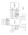
FIG. 1 is an example of a conventional MP3 player. MP3 player includes an interface 106, nonvolatile solid state memory 102, a decoder 110, a digital-to-analog (D/A) converter 147, an audio output 116, a key pad 108, a display 112, a controller 104, RAM 144 and ROM 145.
Controller 104 controls the operation of the MP3 player in accordance with a set of programmed instructions. Programmed instructions for controller 104 are stored in nonvolatile memory or ROM 145, and RAM 144 is provided as the working memory for controller 104
Typically, MP3 data, which is a digital compressed format representing music data, is initially stored on a personal computer 50 and is subsequently transferred to the MP3 player via interface 106, under control of controller 104. The MP3 data is stored in nonvolatile solid state memory 102. Interface 50 can implemented by a standard parallel port, serial port, USB and the like. Nonvolatile solid state memory 102 may be implemented as flash memory. Generally, for a music quality recording, a nonvolatile solid state memory having 64 Mbytes can store about 1 hour of music. Flash memory provides the capability of retaining the stored digital data even when the MP3 player is powered down. Once the digital data has been transferred to the MP3 player, it no longer needs to be connected to personal computer 50, and the MP3 player can play back the MP3 data autonomously from personal computer 50.
Decoder 110 functions to decode and decompress the MP3 data file stored in nonvolatile solid state memory 102. Decoder 110 decompresses the MP3 music file in accordance controller 104 according to the MP3 format, and decodes the decompressed music file into a bit stream form. The bit stream is then converted into analog form by digital to analog converter 147 for connection to a speaker, earphone and the like. A decoding program for the MP3 decoder function is stored in the ROM 145 and loaded to RAM 144 by controller 104 as required.
The MP3 player comprises a keypad 108 for allowing user control and interaction with the MP3 player. Such control may include power on/power off, music selection and volume. The MP3 also comprises a display 112 for displaying characters or graphics, such as a battery indicator, a play mode indicator, a volume indicator, available memory size and the title of the music being played.
SUMMARY
In general, in one aspect, the invention features a method, apparatus, and computer program for an alarm system. It comprises a master unit; and an alarm monitor comprising an alarm sensor to provide a sensor signal representing alarm conditions; a processor to produce digital data based on the alarm signal; and a media access controller to generate a report signal comprising the digital data; and a transmitter to transmit the report signal to the master unit.
Particular implementations can include one or more of the following features. The processor is further to cause the transmitter to transmit the report signal when the sensor signal meets a predetermined condition. The alarm sensor comprises a camera; and the sensor signal comprises an image captured by the camera. The media access controller is further to generate a packet comprising the digital data; and the transmitter is further to transmit the packet. The media access controller is further to generate an electronic mail message comprising the digital data; and the transmitter is further to transmit the electronic mail message. The alarm monitor further comprises a receiver to receive a further signal comprising a destination address; wherein the media access controller directs the electronic mail message to the destination address. The processor is further to enter a sleep mode when the sensor signal meets a predetermined condition for a predetermined interval; and, when the sensor signal no longer meets the predetermined condition, the processor is further to leave the sleep mode and to cause the transmitter to transmit the report signal. The alarm sensor comprises at least one of the group comprising a seismometer; a barometer; a thermometer; a motion detector; a smoke detector; a carbon monoxide detector; and a glass breakage detector. Implementations comprise a receiver to receive a further signal representing sensor calibration information from the master unit; wherein the media access controller is further to obtain the sensor calibration information from the further signal; and wherein the processor is further to calibrate the alarm sensor in accordance with the sensor calibration information. The alarm system complies with a standard selected from the group consisting of IEEE 802.11; IEEE 802.11a; IEEE 802.11b; IEEE 802.11g; IEEE 802.11h; and IEEE 802.11i. The processor and the media access controller are implemented together as a single integrated circuit. The alarm sensor, the processor and the media access controller are implemented together as a single integrated circuit.
In general, in one aspect, the invention features a method, apparatus, and computer program for an alarm system. It comprises receiving a signal representing digital data; obtaining the digital data from the signal representing the digital data; and producing a control signal based on the digital data; and providing the control signal to an actuator to manipulate a physical portal in response to the control signal.
Particular implementations can include one or more of the following features. It comprises manipulating the physical portal in response to the control signal. Manipulating the physical portal is selected from the group consisting of opening the physical portal; closing the physical portal; locking the physical portal; and obscuring the physical portal. The physical portal is selected from the group consisting of a window; and a door. It comprises receiving a sensor signal provided by one or more sensors; and providing the control signal based on the digital data and the sensor signal. The one or more sensors comprise at least one of the group comprising a thermometer; a light detector; a moisture detector; a wind detector; a barometer; a motion detector; a smoke detector; a gas detector; and a glass breakage detector. It comprises providing a keypad control signal in response to operation of a keypad; and providing the control signal based on the digital data and the keypad control signal. It comprises displaying a status of the apparatus. It comprises transmitting a report signal representing a status of the apparatus. It comprises storing an actuator schedule; and producing the control signal based on the actuator schedule. It comprises producing the control signal based on the actuator schedule when the signal representing the digital data is unavailable.
In general, in one aspect, the invention features a physical portal comprising a processor to produce digital data based on a sensor signal provided by a sensor; a media access controller to generate a report signal comprising the digital data; and a transmitter to transmit the report signal.
Particular implementations can include one or more of the following features. The physical portal is selected from the group consisting of a window; and a door. The processor is further to cause the transmitter to transmit the report signal when the sensor signal meets a predetermined condition. The sensor comprises a camera; and wherein the sensor signal comprises an image captured by the camera. The media access controller is further to generate a packet comprising the digital data; and wherein the transmitter is further to transmit the packet. The media access controller is further to generate an electronic mail message comprising the digital data; and wherein the transmitter is further to transmit the electronic mail message. The physical portal further comprises a receiver to receive a further signal comprising a destination address; wherein the media access controller directs the electronic mail message to the destination address. The processor is further to enter a sleep mode when the sensor signal meets a predetermined condition for a predetermined interval; and wherein, when the sensor signal no longer meets the predetermined condition, the processor is further to leave the sleep mode and to cause the transmitter to transmit the report signal. The physical portal further comprises the sensor. The sensor comprises at least one of the group comprising a thermometer; a light detector; a moisture detector; a wind detector; a barometer; a motion detector; a smoke detector; a gas detector; and a glass breakage detector. The sensor, the processor and the media access controller are implemented together as a single integrated circuit. The physical portal further comprises a receiver to receive a further signal representing sensor calibration information; wherein the media access controller is further to obtain the sensor calibration information from the further signal; and wherein the processor is further to calibrate the sensor in accordance with the sensor calibration information. The transmitter complies with a standard selected from the group consisting of IEEE 802.11; IEEE 802.11a; IEEE 802.11b; IEEE 802.11g; IEEE 802.11h; and IEEE 802.11i. The processor and the media access controller are implemented together as a single integrated circuit. The physical portal further comprises a receiver to receive a signal representing digital data; wherein the media access controller is further to obtain the digital data from the signal representing the digital data; wherein the processor is further to produce a control signal based on the digital data obtained by the media access controller; and an output circuit to provide the control signal to an actuator to manipulate the physical portal in response to the control signal. The physical portal further comprises the actuator. The actuator is selected from the group consisting of a device to open the physical portal; a device to close the physical portal; a device to lock the physical portal; and a device to obscure the physical portal. The processor is further to provide the control signal based on the digital data obtained by the media access controller and the sensor signal. The physical portal further comprises a keypad to provide a keypad control signal in response to operation of the keypad; wherein the processor is further to provide the control signal based on the digital data obtained by the media access controller and the keypad control signal. The physical portal further comprises a display to display a status of the physical portal. The receiver is a wireless receiver. The receiver complies with a standard selected from the group consisting of IEEE 802.11; IEEE 802.11a; IEEE 802.11b; IEEE 802.11g; IEEE 802.11h; and IEEE 802.11i. The physical portal further comprises a memory to store an actuator schedule; and wherein the processor is further to produce the control signal based on the actuator schedule. The processor is further to produce the control signal based on the actuator schedule stored in the memory when the signal representing the digital data is unavailable. The memory is non-volatile.
The details of one or more implementations are set forth in the accompanying drawings and the description below. Other features will be apparent from the description and drawings, and from the claims.
DESCRIPTION OF DRAWINGS
FIG. 1 is a block diagram of a conventional MP3 player.
FIG. 2 is a block diagram of a first embodiment of a media player/recorder in accordance with the present invention.
FIG. 3 is a more detailed block diagram of a first embodiment of the media player/recorder of FIG. 2.
FIG. 4 is a block diagram of a second embodiment of a media player/recorder in accordance with the present invention.
FIG. 5 is a more detailed block diagram of the media player/recorder of FIG. 4.
FIG. 6 shows an exemplary data format of a magnetic disk having a plurality of concentric tracks comprised of a plurality of user data sectors and embedded servo data sectors.
FIG. 7 is a schematic representation of memory 202.
FIG. 8 is a memory map of memory 202.
FIG. 9 is flow chart of an energization/deenergization procedure according to a first embodiment of the present invention.
FIG. 10 is flow chart of an energization/deenergization procedure according to a second embodiment of the present invention.
FIG. 11 is flow chart of an energization/deenergization procedure according to a third embodiment of the present invention.
FIG. 12 is flow chart of an operating procedure according to the present invention.
FIG. 13 shows a variation of the first embodiment of the media player/recorder of FIG. 2.
FIG. 14 shows a variation of the second embodiment of the media player/recorder of FIG. 2.
FIG. 15 is a block diagram of a third embodiment of a media player/recorder in accordance with the present invention.
FIG. 16 is a block diagram of a fourth embodiment of a media player/recorder in accordance with the present invention.
FIG. 17 illustrates a mode of some implementations referred to as “local radio mode.”
FIG. 18 shows an implementation where a media player/recorder is implemented within a digital camera.
FIG. 19 shows automobiles equipped with a media player/recorder in accordance with the present invention.
FIG. 20 shows an implementation where a media player/recorder communicates with a biometric sensor over a cable.
FIG. 21 show a biometric sensor worn on a finger and transmitting biometric data over a cable.
FIG. 22 shows a process for a media player/recorder to acquire shared media.
FIG. 23 shows a process for a media player/recorder to share media.
FIG. 24 shows a process for a media player/recorder to match items of interest.
FIG. 25 shows an alarm system according to an embodiment of the present invention.
FIG. 26 shows a controller according to an embodiment of the present invention.
FIG. 27 shows a process that can be performed by the controller of FIG. 26 according to a preferred embodiment.
FIG. 28 shows a window according to one embodiment.
FIG. 29 shows a process that can be performed by the window of FIG. 28 according to one embodiment.
The leading digit(s) of each reference numeral used in this specification indicates the number of the drawing in which the reference numeral first appears. Like reference numerals refer to like parts.
DETAILED DESCRIPTION
Embodiments of the present invention are directed to an alarm system that transmits digital data representing alarm conditions such as weather conditions, motion, gas content, sounds, and so on. The digital data can be encoded, compressed or both, and can be transmitted wirelessly or by wire, cable, or the like.
Referring to FIG. 2 there is shown the first embodiment of media player/recorder of the present invention. The media player/recorder includes a wired interface 206, a wireless interface 210, memory 202, a processor 300, an output 216, a keypad 208, a display 212, a storage device (the storage device may utilize, for example, a magnetic media (such as a hard disk drive), magneto-optical media, an optical media (such as a CD ROM, CDR, CDRW or the like), and the like) such as, a disk drive 230, a preamp 232 and a voice coil motor (VCM) 234. Wireless interface 210 includes a wireless transmitter 209 and a wireless receiver 211.
The operation of the media player/recorder is as follows. Operation of the media player/recorder is controlled by the user through keypad 208. Status of the media player/recorder is provided to the user by display 212.
Media data, which was previously digitized, may be obtained (downloaded) from a personal computer, network appliance, local area network, Internet 50 and the like, including wireless networks with infrastructure, such as a designated access point, peer-to-peer wireless networks, and the like. Such external devices communicate with the media player/recorder via wired interface 206 and wireless interface 210, which are controlled by processor 300. Wired interface 206 may be implemented, for example, as a parallel interface, serial interface, USB, Ethernet connection, IEEE 1394 (a.k.a. Firewire), and the like. Wireless interface 210 may be implemented, for example, as an infrared interface, IEEE 802.15, IEEE 802.11, Bluetooth™ and the like. Again the present invention is independent of the interface selected. Media data is then stored on the storage device such as, disk drive 230 in accordance with processor 300. Disk drive 230 is preferably a miniature drive with a capacity of 1 Gbyte of data storage, which is particularly suitable for a portable device. Of course, any other appropriate sized disk drive may be employed.
Alternatively, media data may be obtained directly from an external analog source, such as a microphone or video camera, connected to input 214. Input 214 takes the input signal from external device and sets the analog signal to an appropriate level. The analog signal is then converted to a digital signal and compressed using a selected format by processor 300, as will be described herein below. The compressed digital data is similarly stored on disk drive 230.
When the user chooses a selection of media data to be played back with keypad 208, processor 300 powers up disk drive 230 and retrieves the selected data which is then transferred to memory 202. It is noted that the powering up of the device is done in a sequential manner so as to minimize energy consumption of the device. A more detailed description is provided below.
Memory 202 comprises a solid state memory, such as, for example dynamic random access memory (solid state memory), flash memory, EEPROM, or the like. It is not necessary for memory 202 to be nonvolatile since the media data is stored in a nonvolatile manner on storage device or disk drive 230. The quantity of solid state memory required is less than is required in a conventional MP3 player. The quantity of solid state memory contemplate is about 2 Mbytes, which is sufficient to store about 2 minutes of MP3 data. Of course, as will be appreciated by one of ordinary skill in the art, when dealing with video data, more solid state memory may be required. The amount of solid state memory supplied is selected to minimize energy consumption.
After the selected data is stored in memory 202, disk drive 230 is then powered down. In this manner, during playback disk drive 230 is powered up only during the transfer of the selected media data from disk drive 230 to memory 202, which results in lower energy consumption. A more detailed description of the powering down of disk drive 230 is provided herein below. The media data is retrieved from memory 202. Processor 300 determines the format of data compression from the retrieved data. Disk drive 230, also stores the data compression/decompression algorithms. The data is decompressed in accordance with the determined format and converted to an analog signal by processor 300. The analog signal is set to an appropriate level by output circuit 216. If the analog signal contains audio data, output circuit 216 is connected to a speaker, headphone and the like for playback, and if the analog signal contains video data, output circuit 216 is connected to a display device for playback.
Additionally, media data recorded on disk drive 230 or stored in memory 202 may be transferred (uploaded) to a personal computer, network appliance, local area network, internet 50 or another media player/recorder through interfaces 206 and 210 under the control of processor 300.
FIG. 3 is a detailed block diagram of processor 300. Processor 300 is preferably implemented as a single integrated circuit. A media playback/recorder apparatus having a processor implemented as a single integrated circuit can be fabricated at lower cost and have lower energy consumption. Alternatively, processor 300 may be implemented by discrete components. Processor 300 comprises a read channel 341, storage controller or hard disk controller 342, digital signal processor/microprocessor unit (DSP/MPU) 343, random access memory (RAM) 344, a non volatile memory such as read only memory (ROM) 345, digital to analog converter (DAC) 346 and analog to digital converter (ADC) 347. DSP/MPU 343 comprises servo controller 349 and Codec 348. In a preferred embodiment, DSP/MPU 343 is implemented as a single integrated circuit. In another embodiment, MPU may be implemented as one integrated circuit and the DSP may be implemented as another integrated circuit.
It is noted that DSP/MPU 343 may comprise a microprocessor unit, a digital signal processor, or any combination thereof. ROM 345 stores programmed instructions for processor 300 and DSP/MPU 343 to control the operation of both the disk drive 230 (and associated circuitry) and the signal processing of the media data. RAM 345 is provided as a working memory for DSP/MPU 343. For each of the various compression formats discussed above, the decompression and compression algorithms for Codec 348 are stored on disk drive 230. Storing the decompression and compression algorithms on disk drive 230 minimizes the size of ROM 345 and its energy consumption. Additionally, this feature allows future compression and decompressions formats to be easily implemented for the media player/recorder.
In the implementation of FIG. 3, wireless interface 210 is implemented separately from processor 300, and includes an antenna 356, a wireless unit 354, a baseband processor 352, and a media access controller (MAC) 350. Antenna 356 is a conventional antenna for receiving and transmitting wireless signals. Wireless unit 354 converts wireless signals received by antenna 356 to analog baseband signals, and converts analog baseband signals received from baseband processor 352 to wireless signals for transmission by antenna 356. Baseband processor 352 converts analog baseband signals received from wireless unit 354 to a digital bitstream, and converts a digital bitstream received from MAC 350 to analog baseband signals, both according to well-known methods. MAC 350 frames the digital bitstream produced by baseband processor 352, and filters the frames to select the frames addressed to processor 300, both according to well-known methods. MAC 350 also converts frames received from processor 300 to a digital bitstream for baseband processor 352, also according to well-known methods. In some implementations, MAC 350 includes an embedded microprocessor.
Prior to discussing the operation of processor 300, reference is made to FIG. 6. FIG. 6 shows an exemplary data format of a magnetic media used in disk drive 230, comprising a series of concentric data tracks 13 wherein each data track 13 comprises a plurality of sectors 15 with embedded servo wedges 17. Servo controller 349 processes the servo data in servo wedges 17 and, in response thereto, positions the read/write head over a desired track. Additionally, servo controller 349 processes servo bursts within servo wedges 17 to keep a disk head of disk drive 230 aligned over a centerline of the desired track while writing and reading data. Servo wedges 17 may be detected by the discrete time sequence detector implemented in DSP/MPU 343. It is important to note that DSP/MPU 343 is utilized only during the time period for detecting servo wedges 17; during other periods DSP/MPU 343 is available to perform other functions as described below, such as signal processing for media data playback and recording. By using only one DSP rather than two, the cost of fabrication and the amount of energy consumption can be reduced.
As described above, the powering up of the device is done in a sequential manner so as to minimize energy consumption of the device. More specifically, the mechanical or motor portions of the storage device are energized first. After the motor reaches operating speed, VCM 234 is energized, followed by the energization of read channel 341 and HDC 342.
The operation of processor 300 is as follows. DSP/MPU 343 controls the entire operation of the media player/recorder. DSP/MPU 343 is coupled to hard disk controller 342. When writing data to disk drive 230, hard disk controller 342 receives a write instruction and write data from DSP/MPU 343. The write data is temporarily stored in a cache memory (not shown) which is used as a buffer memory. Based on a clock from a clock generator (not shown), DSP/MPU 343 controls voice coil motor (VCM) and spindle motor 234 via servo unit 349. As a result, the magnetic head is moved to a desired track position on the magnetic disk by the head arm, and the magnetic disk is rotated at a rated rotational speed by the spindle, which is driven by spindle motor 234. The data is read from the cache memory and supplied to read channel 341 via hard disk controller 342. Read channel 341 encodes the write data under the control of DSP/MPU 343, and supplies the encoded write data to preamplifier 232. The magnetic head writes the encoded write data on the magnetic disk in accordance with a signal from preamplifier 232.
When reading data from the magnetic disk, hard disk controller 342 receives a read instruction from DSP/MPU 343. Based on a clock signal, DSP/MPU 343 controls voice coil motor and spindle motor 234 via servo unit 349. Hence, the magnetic head is moved to a desired track position on the magnetic disk by the head arm, and the magnetic disk is rotated by spindle motor 234.
The data read from the magnetic disk by the magnetic head is supplied to read channel 341 via preamplifier 232. Read channel 341 decodes the read data under the control of DSP/MPU 343, and generates read data. The read data are supplied from read channel 341 to hard disk controller 342 under the control of DSP/MPU 343, and are temporarily stored in the cache memory. The read data read from the cache memory are supplied to DSP/MPU 343 from hard disk controller 342.
As noted above, operation of the media player/recorder is controlled by the user through keypad 208, which is in communication with DSP/MPU 343. Status of the media player/recorder is provided to the user by display 212 in accordance with DSP/MPU 343. When either uploading or downloading data, the media player/recorder is in communication with personal computer, network appliance, local area network, Internet 50. Otherwise the media player/recorder can be operated independently. The user selects the file to be downloaded from personal computer, network appliance, local area network, Internet 50 by way of keypad 208. Alternatively the user can select the file to be downloaded from the personal computer. DSP/MPU 343 controls the flow of data through interfaces 206 and/or 210 and stores the data onto hard disk 230 in accordance with the method described above. When uploading data to personal computer, network appliance, local area network, Internet 50 the process is reversed.
To record data directly input into media player/recorder from an external analog source, the external device is placed in communication with input 214. Input 214 takes the input signal from the external device and sets the analog signal to an appropriate level. The analog signal is then converted to a digital signal by ADC 347 of processor 300. Codec 348 of DSP/MPU 343 compresses the digitized data using a default compression format or one selected by the user by way of keypad 208. The default or selected compression program is transferred from hard disk 230 to RAM 344 and provided to Codec 348 for encoding. The compressed digital data is similarly stored on disk drive 230 under the control of DSP/MPU 343.
When the user chooses a selection of media data to be played back with keypad 208, DSP/MPU 343 powers up disk drive 230 and retrieves the selected data as described above. The retrieved data is then written to memory 202. After the selected data is stored in memory 202, disk drive 230 is then powered down by DSP/MPU 343. In this manner, during playback disk drive 230 is powered up only during the transfer of the selected media data from disk drive 230 to memory 202, which results in lower energy consumption. A single song stored in MP3 format may take approximately one second to retrieve from disk drive 230. The media data is retrieved from memory 202 by DSP/MPU 343 and the compression format is then determined.
If the decompression program has already been transferred to RAM 344, the program is provided to Codec 348. Otherwise the decompression algorithm is retrieved from hard disk 230 and transferred to RAM 344. The data is then decompressed by Codec 348 and converted to an analog signal by DAC 346. The analog signal is set to an appropriate level by output circuit 216. If the analog signal contains audio data, output circuit 216 is connected to a speaker, headphone and the like for playback, and if the analog signal contains video data, output circuit 216 is connected to a display device for playback.
It is noted that the capacity of disk drive 230 is selected to hold a desired amount of media data, and the amount of solid state memory 202 is selected to minimize energy consumption. A disk drive having a capacity of 1 Gbyte can store approximately 30 hours of MP3 compressed music.
This section will described the power management control of the device by CPU/MPU 343.
Referring now to FIGS. 3, 7 and 9, when the user turns on the media player and selects a file to be played (step 912), the various components of media player are powered up in a sequential manner so as to minimize energy consumption of the device. More specifically, the mechanical or motor portions of the storage device or disk drive 230 are energized first (step 914). After the motor reaches its operating speed (step 916), VCM 234, preamp 232, read channel 341 and HDC 342 are energized, since these components are only functional after disk drive 230 becomes operational. Energy would be unnecessarily expended if preamp 232, read channel 341 and HDC 342 were energized before disk drive 230 becomes operational. Therefore, VCM 234, preamp 232, read channel 341 and HDC 342 are energized only after disk drive 230 becomes operational (step 918). Preamp 232, read channel 341 and HDC 342 can be referred to as a storage circuit and include circuits to transform data stored on a storage device to a digital signal.
FIG. 7 is a schematic representation of memory 202. User data is first stored from location 724 to location 702 in a sequential manner in memory 202. In one embodiment, DSP/MPU 343 uses a pointer system in connection with memory 202 to determine when the amount of data stored the amount data stored reaches an upper threshold value (step 922). When the amount of data stored in memory 202 reaches the upper threshold value, HDC 342, read channel 341, preamp 232, disk drive 230 and VCM 234 are powered down or deenergized (step 924). Of course, as will be appreciated by one of ordinary skill in the art, while data is being to memory 202, data may also be read contemporaneously therefrom by DSP/MPU 343 for decompression and playback. Data is then read out from memory 202 starting at location 702 towards location 724 by DSP/MPU 343 (step 926). When the data file has been completely read from memory (step 928), the user can select another file. The data is continually read from memory 202, until the amount of data remaining is below a low threshold value (step 930). When the data remaining in memory 202 is below the threshold value, disk drive 230, VCM 234, preamp 232, read channel 341 and HDC 342 are sequentially energized as noted above, and data is transferred from the storage device to memory 202.
FIG. 10 is an alternate embodiment to FIG. 9. Instead of utilizing a pointer system, the amount of data transferred to memory 202 is counted (step 1020) by a counter incorporated in DSP/MPU 343. The sequential energization of the disk drive 230, VCM 234, preamp 232, read channel 341 and HDC 342 is similar to that of the embodiment of FIG. 9 ( steps 1012, 1014, 1016 and 1018). When amount of data transfer to memory 202 is greater than or equal to an upper limit U (step 1022), HDC 342, read channel 341, preamp 232, disk drive 230 and VCM 234 are powered down or deenergized (step 1024). As data is read from memory, the counter decrements the count, and when the count is less than or equal to a lower limit 1 (step 1030), disk drive 230, VCM 234, preamp 232, read channel 341 and HDC 342 are sequentially energized as noted above, and data is transferred from the storage device to memory 202.
FIG. 11 is another alternate embodiment to FIG. 9. The embodiment in FIG. 9 utilizes a timer incorporated in DSP/MPU 343 to approximate the amount of data transferred to memory 202 in accordance with the data transfer rate of disk drive 230. The sequential energization of disk drive 230, VCM 234, preamp 232, read channel 341 and HDC 342 is similar to that of the embodiment of FIG. 9 ( steps 1112, 1114, 1116 and 1118). The timer is started (step 1119) as data is transferred form disk drive 230 to memory 202. When the timer times out, HDC 342, read channel 341, preamp 232, disk drive 230 and VCM 234 are powered down or deenergized (step 1124). As data is read from memory, the timer is started (1125), and when the timer times out (step 1130), disk drive 230, VCM 234, preamp 232, read channel 341 and HDC 342 are sequentially energized as noted above, and data is transferred from the storage device to memory 202.
In the simplest implementation, media data representing one selection (such as a single song) is transferred from disk drive 230 to memory 202 for playback. FIG. 8 is a schematic representation of memory 202, and FIG. 12 is a flow chart illustrating an alternate implementation. As shown therein, instead of retrieving just one selection, first portions of multiple selections are transferred from disk drive 230 to memory 202. These multiple selections may include the user's favorite selections, random selections from an external source, or the like (step 1204). When the user starts playing back the selection, a timer is started (step 1208) and the first selection is played back (step 1210). If a user instruction is received (step 1212) to continue playing that selection is received within a predetermined time (step 1214), the remaining portion of the selection is transferred from disk drive 230 to memory 202 (step 1216) for continued play back (step 1218). If the timer times out (step 1214), the first portion of the next selection (step 1206) is played back and the process is repeated for each remaining first portion. Alternatively, instead of using a timer, a memory threshold, as shown in FIG. 8, may be utilized permit playback of the entire current selection if the user instruction is received before the memory being read out goes below the current selection threshold. Otherwise the first portion of the next selection is played back. Of course, the play back of portions of selections 1 through N may be in any order, such as sequential, random and predetermined. If the play back is in sequential order new selections may be transferred from disk drive 230 to memory 202 to replace previously played back selections.
FIGS. 4 and 5 show a second embodiment of the present invention. The second embodiment is similar to the first embodiment except the second embodiment does not include memory 202. In this embodiment media data is recorded in a similar manner as the first embodiment and no further discussion is provided herein. For playback operation, the media data is retrieved directly from disk drive 230 for playback through output 216. The other portions of the playback operation are similar to the first embodiment. In the second embodiment disk drive 230 will be powered on any time media data is recorded or played back. As such this embodiment is particularly applicable when the power supply is external. For example the media player/recorder of the second embodiment may be a portable device used in an automobile supply by energy therefrom. In some implementations, MAC 350 includes an embedded microprocessor.
FIG. 13 shows a variation of the first embodiment. According to this variation, baseband processor 352 and MAC 350 are implemented within processor 300, preferably as a single integrated circuit. Wireless interface 210 includes antenna 356 and wireless unit 354. This variation operates as described for the first embodiment. In some implementations, MAC 350 includes an embedded microprocessor.
FIG. 14 shows a variation of the second embodiment. According to this variation, baseband processor 352 and MAC 350 are implemented within processor 300, preferably as a single integrated circuit. Wireless interface 210 includes antenna 356 and wireless unit 354. This variation operates as described for the first embodiment. In some implementations, MAC 350 includes an embedded microprocessor.
FIG. 15 is a block diagram of a third embodiment of a media player/recorder in accordance with the present invention. According to this embodiment, a MAC 1550 is implemented within processor 300, which is preferably implemented as a single integrated circuit, and includes an embedded digital signal processor and microprocessor unit (DSP/MPU) 1551. DSP/MPU 1551 includes codec 348, and communicates with memory 202, display 212, keypad 208, wired interface 206, RAM 344, DAC 346, and ADC 347, which function as described above with reference to FIG. 3. DSP/MPU 343 has been replaces with DSP/MPU 1543, which controls disk drive 230, read channel 341, and HDC 342 as described above.
FIG. 16 is a block diagram of a fourth embodiment of a media player/recorder in accordance with the present invention. This embodiment is similar to the above embodiments, but has no hard drive. Some implementations of this embodiment optionally include a non-volatile memory 1602 such as a flash memory instead of a hard drive. Consequently the circuits associated with the hard drive are also eliminated, resulting in a less-expensive media player/recorder. In the depicted implementation, baseband processor 352 and MAC 350 are implemented within processor 300, which is preferably implemented as a single integrated circuit. In other implementations, baseband processor 352 and MAC 350 are implemented separately from processor 300, for example, within wireless interface 210. In some implementations, MAC 350 includes an embedded DSP/MPU. These implementations operate in a manner similar to that described for the implementations of FIG. 15.
The implementations using non-volatile memory instead of a hard drive are especially useful for receiving streaming media from broadcasts such as internet radio stations and other media player recorders. Some implementations feature a “broadcast” mode where the media player/recorder plays a media selection and wirelessly transmits the media selection, either compressed or uncompressed, or in analog form, such that other media player/recorders can receive the broadcast media and play it at the same time as the broadcasting player/recorder.
The implementations with no hard drive or non-volatile memory are especially useful in a “local radio” mode where the media to be played is stored on a personal computer, server, or the like that is separate from the media player/recorder. FIG. 17 illustrates the local radio mode. In this mode, the media is wirelessly streamed to the media player/recorder 1704, which decompresses and plays the media without storing the media. Because the media player/recorder never stores a copy of the media, it is ideal for playing media for which only a single copy is licensed. The single copy is stored on a personal computer (PC) 1702, and is streamed to media player/recorder 1704 for playback. Because only a single copy of the media is stored, the single-copy license is satisfied.
FIG. 18 shows an implementation where a media player/recorder 1804 is implemented within a digital camera 1802. In recording mode, an image sensor 1806 within camera 1802 captures one or more images, and passes a signal representing the image to media player/recorder 1804. If the signal is analog, a analog-to-digital converter within media player/recorder 1804 converts the analog signal to a digital signal. A digital signal processor within media player/recorder 1804 then encodes the digital signal. The encoding can include image compression, image manipulation, and the like. A storage controller within media player/recorder 1804 stores the encoded image data on a storage device. In some implementations, digital camera 1802 is a digital motion picture camera and the encoded image data represents a motion picture.
In playback mode, the storage controller retrieves the encoded image data from the storage device. The digital signal processor decodes the retrieved encoded image data. Media player/recorder 1804 sends a signal representing the decoded image data to a display 1808, which displays the image(s) captured by image sensor 1806. A The media player/recorder described herein can be implemented as a portable unit, as a permanently mounted unit within a vehicle such as an automobile, and the like. FIG. 19 shows automobiles 1902A and 1902B equipped with such a media player/recorder. In this implementation, the antenna of the automobile can serve as the antenna of the media player/recorder. The media player/recorders in the automobiles 1902 can communicate with each other, without user intervention, while traveling near each other, while stopped at intersections, and in other similar scenarios, to share media data, items of interest, and the like. The media player/recorders in the automobiles 1902 can also communicate with portable media player/recorders 1904 in a similar fashion. The vehicular and portable media player/recorders can communicate with a stationary base station 1906 to share media over a network such as the Internet. For example, a homeowner can equip his garage with such a base station 1906 so the media player/recorder in his automobile can share media and items of interest while parked in the garage during the night. Similarly, a user of a portable player/recorder 1904 can equip his home with a base station 1906 so the media player/recorder 1904 can share media and items of interest while not otherwise in use, for example while the user sleeps.
Some implementations receive and store data other than media data. In some implementations the media player/recorder records biometric data collected by a biometric sensor disposed near, upon, or within a human body or other organism. The biometric data can represent biological functions such as breathing, heart function, body temperature, blood pressure, and the like. Such devices and methods are well-know in the relevant arts, and are described in U.S. Pat. No. 6,023,662 entitled “Measurement Device, Portable Electronic Instrument, And Measurement Method,” issued Feb. 8, 2000; U.S. Pat. No. 6,030,342 entitled “Device For Measuring Calorie Expenditure And Device For Measuring Body Temperature,” issued Feb. 29, 2000; U.S. Pat. No. 6,036,653 entitled “Pulsimeter,” issued Mar. 14, 2000; and U.S. Pat. No. 6,081,742 entitled “Organism State Measuring Device and Relaxation Instructing Device,” issued Jun. 27, 2000, the disclosures thereof incorporated by reference herein in their entirety.
FIG. 20 shows an implementation where a media player/recorder 2002 communicates with a biometric sensor 2004 over a cable 2006. The biometric data collected by biometric sensor 2004 is passed to media player/recorder 2002 over cable 2006. Alternatively, the biometric data can be passed to media/player recorder 2002 wirelessly. The data can be passed in analog or digital form, and is received and stored by media/player recorder 2002 according to the methods described above. In FIG. 20 the biometric sensor is worn on the leg. Of course, the biometric sensor can be worn in other locations. FIG. 21 show a biometric sensor 2104 worn on a finger and transmitting biometric data over a cable 2106.
According to these implementations, a user of the media player/recorder can record biometric data for later use in diagnosis and treatment of intermittently occurring medical conditions such as heart arrhythmia. When the user subsequently visits a doctor, the media player/recorder can transmit the stored biometric data to the doctor's computer for analysis, by wire or wirelessly.
Some implementations feature a “share” mode in which media stored on one media player/recorder can be shared with other media player recorders using wireless data transmissions over wireless interface 210. FIGS. 22 and 23 show methods for such sharing. Of course, media can be shared over wired interface 206 as well using similar methods. However, these methods are well-suited for the relatively lower data rates of wireless links because they require little user intervention. These methods can be used not only to share media between player/recorder units, but also with other repositories of media, such as remote network servers and the like.
FIG. 22 shows a process 2200 for a media player/recorder to acquire shared media. A list of identifiers of desired media selections, such as song titles, is stored within the player/recorder (step 2202). A user can generate the list using the keypad, download the list from a computer, or the like. Optionally, the wireless transmitter can transmit a signal representing the list (step 2204). Other player/recorder units receive the list, and respond by offering media selections on the list. The wireless receiver receives the titles of the offered media selections (step 2206). The offered titles are compared to the desired titles (step 2208). The player/recorder optionally transmits a signal requesting the selections having matching titles (step 2210). Other player/recorders respond by transmitting the requested selections. The player/recorder receives the requested selections, and stores the received selections (step 2212).
The player/recorder can obtain selections shared by a broadcaster that simply transmits a title of a media selection, and then transmits the selection, without first waiting to receive lists of desired titles or requests for media selections having matching titles. In this case optional steps 2204 and 2210 are not needed.
FIG. 23 shows a process 2300 for a media player/recorder to share media. A list of identifiers of shared media selections, such as song titles, is stored within the player/recorder (step 2302). A user can generate the list using the keypad, download the list from a computer, or the like. Optionally, the wireless transmitter can transmit a signal representing the list (step 2304). Other player/recorder units receive the list, and respond by requesting media selections on the list. The wireless receiver receives the titles of the sought media selections (step 2306). The sought titles are compared to the shared titles (step 2308). The player/recorder transmits the selections having matching titles (step 2310).
Some implementations feature an “interest matching” mode in which items of interest stored on one media player/recorder can be shared with other media player recorders using wireless data transmissions over wireless interface 220. Items of interest include interests such as hobbies and sports, items for sale or rent, requests for items for sale or rent, musical preferences and the like. When a match is made, the display units indicate the match, and the media player/recorders can wirelessly exchange contact information such as email addresses, telephone numbers and the like. Some implementations include a directional antenna to allow the users having matched items of interest to locate each other. Of course, interests can be matched over wired interface 216 as well using similar methods. FIG. 24 shows methods for such interest matching.
FIG. 24 shows a process 2400 for a media player/recorder to match items of interest. A list of desired items of interest is stored within the player/recorder (step 2402). A user can generate the list using the keypad, download the list from a computer, or the like. Optionally, the wireless transmitter can transmit a signal representing the list (step 2404). The wireless receiver receives offered items of interest from other player/recorders (step 2406). The offered items of interest are compared to the desired items of interest (step 2408). When compared items of interest match, the display unit indicates a match (step 2410). Optionally the player/recorder transmits contact information to the transmitter of the offered item of interest (step 2412). Optionally, the player/recorder determines and displays a direction to the transmitter of the offered item of interest (step 2414). The player/recorder can also include a range finder circuit to determine a range to the transmitter of the offered item of interest, which is then displayed.
FIG. 25 shows an alarm system 2500 according to an embodiment of the present invention. Alarm system 2500 comprises a controller 2510, one or more sensors 2502, one or more actuators 2508, and one or more optional alarm indicators 2520 such as sirens, flashers, and the like. Each sensor 2502 generates a sensor signal that represents alarm conditions. Controller 2510 receives the sensor signal, generates a report signal that represents the alarm conditions, and optionally transmits the report signal to an optional master unit such as a network appliance 2512, personal computer (PC), or the like over a channel 2514 that can be a wireless link or a wire, cable, or the like.
Alarm system 2500 has many uses including intruder alarm systems, fire and smoke detectors, and the like. A single controller 2510 can receive data from one or more sensors 2502, and can control one or more sensors 2502, for example for purposes such as calibration of sensors 2502. Network appliance 2512 can communicate with multiple controllers 2510. Controller 2510 and sensors 2502 can be fabricated as separate units or as a single alarm monitor unit.
Controller 2510 can operate independently or in conjunction with network appliance 2512. When operating in conjunction with network appliance 2512, controller 2510 collects data from sensors 2502 and reports the data to network appliance 2512. In some embodiments, controller 2510 regularly reports the data to network appliance 2512. In some embodiments network appliance 2512 polls controller 2510. In other embodiments, controller 2510 only reports the data to network appliance 2512 when the data meets one or more predetermined conditions, which can be downloaded from network appliance 2512. For example, in an intruder alarm system where sensor 2502 is a motion detector, controller 2510 transmits a report signal to network appliance 2512 only when sensor 2502 detects motion. In some embodiments, controller 2510 can report data from a second sensor when data from a first sensor meets one or more predetermined conditions. For example, in an intruder alarm system where sensors 2502 include a motion detector and a camera, controller 2510 can transmit data captured by the camera when the motion detector detects motion.
In some embodiments, controller 2510 features a low-power sleep mode where one or more elements of controller 2510, such as a processor and so on, enters the sleep mode when the sensor signal meets a predetermined condition for a predetermined interval. When the sensor signal no longer meets the further predetermined condition, the sleeping elements leave the sleep mode and controller 2510 can transmit the report signal.
When operating independently, controller 2510 can rely on data previously provided by network appliance 2512 such as predetermined conditions previously downloaded. In some embodiments, controller 2510 causes an alarm indicator 2520 to produce an audible or visual alarm indication in response to controller 2510 when a predetermined condition is met. In other embodiments, system 2500 operates as a silent alarm system, instead reporting events over an optional plain old telephone system (POTS) 2518 or an optional network 2516 such as a LAN, MAN, WAN, the Internet, or the like.
Controller 2510 can communicate over wired or wireless channels. Wireless implementations can be ad hoc or infrastructure. Infrastructure implementations include an access point 2504, which can also communicate with network 2516, and with POTS 2518 over a modem 2506. In such implementations, controller 2510 and access point 2504 can be fabricated separately or as a single unit.
In embodiments including an optional display, controller 2510 can display information such as the status of controller 2510, the status of sensors 2502, and so on. In embodiments including an optional keypad, a user can operate the keypad to alter the operation of controller 2510, for example by changing the conditions for the sleep mode and for transmitting the report signal. In other embodiments the user can alter the operation of controller 2510 by speaking a command aloud. This sound is captured by an input circuit, and interpreted as a control signal.
Alarm system 2500 has many uses. For example, in embodiments where alarm system 2500 comprises a fire alarm system, sensors 2502 can comprise thermometers, smoke detectors, and the like. In embodiments where alarm system 2500 comprises a gas alarm system, sensors 2502 can comprise carbon monoxide detectors and other gas detectors. In embodiments where alarm system 2500 comprises an intruder alarm system, sensors 2502 can comprise motion detectors, glass breakage detectors, and trip sensors to detect the opening of a window or door. In embodiments where alarm system 2500 comprises an earthquake reporting system, sensors 2502 can comprise seismometers and the like. In embodiments where alarm system 2500 comprises a weather reporting system, sensors 2502 can comprise thermometers, barometers, rain gauges, and other weather instruments. Other such systems are within the scope of the present invention and will be apparent to one skilled in the relevant arts after reading this description.
FIG. 26 shows a controller 2600 according to an embodiment of the present invention that can function as controller 2510 of FIG. 10. Controller 2600 includes a processor 2618 that includes a microprocessor unit (MPU) 2640, a volatile memory such as random access memory (RAM) 2624, a non-volatile memory such as read only memory (ROM) 2626, an optional digital to analog converter (DAC) 2628, an optional analog to digital converter (ADC) 2630, a media access controller (MAC) 2622, and a baseband processor 2620. Processor 2618 is preferably implemented as a single integrated circuit. A controller having a processor implemented as a single integrated circuit can be fabricated at lower cost and have lower energy consumption. Alternatively, processor 2618 can be implemented by discrete components. In some embodiments, processor 2618 is implemented together with one or more sensors 2502 as a single integrated circuit.
MPU 2640 can comprise a microprocessor unit, a digital signal processor, or any combination thereof. ROM 2626 stores programmed instructions for processor 2618 and MPU 2640. RAM 2626 is provided as a working memory for MPU 2640.
Controller 2600 also includes an interface, which can be a wired interface 2606, a wireless interface 2610, or a combination of the two. Controller 2600 further includes a memory 2602, an optional input circuit 2614, an optional output circuit 2616, an optional keypad 2608, and an optional display 2612. Wireless interface 2610 includes a wireless antenna 2632 and a wireless unit 2610 that includes a wireless receiver 2638 and an optional wireless transmitter 2636. Wired interface 2606 includes a receiver 2646 and an optional transmitter 2648. Keypad 2608 can be fabricated together with display 2612 as a touch screen.
Memory 2602 comprises a solid state memory, such as, for example dynamic random access memory (solid state memory), flash memory, EEPROM, or the like. The amount of solid state memory supplied is selected to minimize energy consumption.
Antenna 2632 is a conventional antenna for receiving and transmitting wireless signals. Wireless unit 2610 converts wireless signals received by antenna 2632 to analog baseband signals, and converts analog baseband signals received from baseband processor 2620 to wireless signals for transmission by antenna 2632. Baseband processor 2620 converts analog baseband signals received from wireless unit 2610 to a digital bitstream, and converts a digital bitstream received from MAC 2622 to analog baseband signals, both according to well-known methods. MAC 2622 frames the digital bitstream produced by baseband processor 2620, and filters the frames to select the frames addressed to processor 2618, both according to well-known methods. MAC 2622 also converts frames received from processor 2618 to a digital bitstream for baseband processor 2620, also according to well-known methods. In some implementations, MAC 2622 includes an embedded microprocessor.
Digital data may be transferred between controller 2600 and a master unit such as network appliance 2512, a local area network, the Internet and the like, including wireless networks with infrastructure, such as a designated access point, peer-to-peer wireless networks, and the like. Such external devices communicate with the controller via wired interface 2606 and/or wireless interface 2610, which are controlled by processor 2618. Wired interface 2606 may be implemented, for example, as a parallel interface, serial interface, USB, Ethernet connection, IEEE 1394 (a.k.a. Firewire), and the like. Wireless interface 2610 may be implemented, for example, as an infrared interface, IEEE 802.15, IEEE 802.11, Bluetooth™ and the like. Some embodiments of the present invention comply with one or more of the following standards: IEEE 802.11; IEEE 802.11a; IEEE 802.11b; IEEE 802.11g; IEEE 802.11h; and IEEE 802.11i. Again, the present invention is independent of the interface selected. The digital data is then optionally stored in memory 2602. Processor 2618 can obtain digital data directly from a digital sensor 2502, or indirectly over wired interface 2606 or wireless interface 2610.
Alternatively, digital data may be obtained from an external analog source such as an analog sensor 2502 connected to input circuit 2614. Input circuit 2614 takes the input signal from the external device and sets the analog signal to an appropriate level. The analog signal is then converted to a digital signal by ADC 2630. The digital data can be stored in memory 2602.
FIG. 27 shows a process 2700 that can be performed by controller 2600 according to a preferred embodiment. Operation of controller 2600 can be automatic, controlled by the user through optional keypad 2608, which is in communication with MPU 2640, or both. Status of the controller can be provided to the user by optional display 2612 in accordance with MPU 2640.
One or more sensors 2502 generate a sensor signal representing alarm conditions (step 2702). In embodiments where the sensor signal is digital, it can be received by interfaces 2606 and/or 2610. In embodiments where the sensor signal is analog, it can be received by input circuit 2614, which sets the signal to an appropriate level, and converted to a digital signal by ADC 2630. In either case, the sensor signal is passed to processor 2618 and optionally stored in memory 2602.
Processor 2618 produces digital data based on the sensor signal (step 2704). For example, the digital data can represent the sensor signal, or can simply represent an alert triggered by the sensor signal. Media access controller 2622 generates a report signal comprising the digital data according to well-known methods (step 2706).
When controller 2600 is in communication with a personal computer, network appliance, local area network, Internet, or the like, controller 2600 transmits a report signal comprising the digital data (step 2708). MPU 2640 controls the flow of the digital data through interfaces 2606 and/or 2610.
In some embodiments, media access controller 2622 generates a packet comprising the digital data, which is then transmitted. In some embodiments, media access controller 2622 generates an electronic mail message comprising the digital data which is then transmitted to a destination address that can be provided by network appliance 2512 or the like.
In some embodiments, controller 2510 and one or more actuators 2508 are implemented together for controlling a physical portal such as a window or door. In some embodiments, controller 2510 and actuators 2508 are implemented within the physical portal. In other embodiments, controller 2510 and actuators 2508 are implemented within a portal component, such as a lock, that can be installed in a portal.
FIG. 28 shows a window 2800 according to one embodiment. While features of the invention are described with respect to window 2800 and an actuator for opening and closing window 2800, other sorts of physical portals and actuators are contemplated. In addition, features of the invention can be located in different parts of the window, door, or the like, such as in the sash, windowpane, door panel, frame, and so on. Window 2800 comprises a frame 2802 and a sash 2804 that can be moved in a vertical plane to open and close window 2800. Window 2800 also comprises a controller 2510 and an actuator 2508, installed inside window frame 2802 and shown in a cutaway view of window frame 2802, that is to raise and lower sash 2804 according to a control signal provided by controller 2510. In this example, actuator 2508 comprises a motor 2806 and a sash cable 2808 connected between motor 2806 and sash 2804. Of course window 2800 can include other actuators for other purposes, for example to lock window 2800, or to obscure window 2800 by operating blinds, liquid-crystal display windowpanes, and the like, that are within or external to window 2800.
Window 2800 optionally comprises one or more sensors 2502 that provide a sensor signal. Sensors 2502 can comprise a thermometer, a light detector, a moisture detector, a wind detector, a barometer, a motion detector, a smoke detector, a gas detector, a glass breakage detector, or other sorts of sensors. As described above, controller 2510 optionally comprises a keypad 2608 and display 2612.
FIG. 29 shows a process 2900 that can be performed by window 2800 according to one embodiment. Controller 2510 receives a signal representing digital data (2902), and obtains the digital data from the signal (step 2904). The digital data can represent an instruction to manipulate window 2800, or information that can be used by controller 2510 to determine when and how to manipulate window 2800. For example, the digital data can represent a schedule for the operation of window 2800. As another example, the digital data can represent current or predicted weather conditions that controller 2510 can use to determine when and how to operate window 2800. For this example, assume the digital data represents a forecast of inclement weather, and therefore controller 2510 has determined to close window 2800 immediately.
Controller 2510 produces a “close window” control signal, and provides the control signal to actuator 2508 (step 2906), causing actuator 2508 to close window 2800. Subsequently, controller 2510 receives sensor signals from sensors 2502 (step 2908) within and/or external to window 2800 that indicate rising temperature, increasing sunlight, falling relative humidity, and rising barometric pressure. Accordingly, controller determines window 2800 should be opened, and provides an “open window” control signal to actuator 2508 (step 2910), causing actuator 2508 to open window 2800.
Subsequently a user observes the status of window 2800 on display 2612 (step 2912), and enters a “close window” command using keypad 2608. In response, controller 2510 produces a “close window” control signal, and provides the control signal to actuator 2508 (step 2914), causing actuator 2508 to close window 2800.
In other embodiments, the user can control window 2800 remotely. Controller 2510 can transmit a report signal representing the status of window 2800. The user receives the report signal, for example as an email message or HTML document on a personal computer. The user enters a window command that is received as a signal by controller 2510, which provides a corresponding control signal to actuator 2508.
If the signal representing the digital data is unavailable, controller 2510 can operate window 2800 according to information provided by sensor 2502 and/or a stored actuator schedule of operation.
The invention can be implemented in digital electronic circuitry, or in computer hardware, firmware, software, or in combinations of them. Apparatus of the invention can be implemented in a computer program product tangibly embodied in a machine-readable storage device for execution by a programmable processor; and method steps of the invention can be performed by a programmable processor executing a program of instructions to perform functions of the invention by operating on input data and generating output. The invention can be implemented advantageously in one or more computer programs that are executable on a programmable system including at least one programmable processor coupled to receive data and instructions from, and to transmit data and instructions to, a data storage system, at least one input device, and at least one output device. Each computer program can be implemented in a high-level procedural or object-oriented programming language, or in assembly or machine language if desired; and in any case, the language can be a compiled or interpreted language. Suitable processors include, by way of example, both general and special purpose microprocessors. Generally, a processor will receive instructions and data from a read-only memory and/or a random access memory. Generally, a computer will include one or more mass storage devices for storing data files; such devices include magnetic disks, such as internal hard disks and removable disks; magneto-optical disks; and optical disks. Storage devices suitable for tangibly embodying computer program instructions and data include all forms of non-volatile memory, including by way of example semiconductor memory devices, such as EPROM, EEPROM, and flash memory devices; magnetic disks such as internal hard disks and removable disks; magneto-optical disks; and CD-ROM disks. Any of the foregoing can be supplemented by, or incorporated in, ASICs (application-specific integrated circuits).
A number of implementations of the invention have been described. Nevertheless, it will be understood that various modifications may be made without departing from the spirit and scope of the invention. Accordingly, other implementations are within the scope of the following claims.

Claims (53)

1. An alarm monitor comprising:
memory that stores an actuator schedule;
an input circuit that receives a sensor signal that indicates an alarm condition, the sensor signal originating from a sensor that is remote from the alarm monitor;
a processor that generates digital data based on said sensor signal and that generates a first control signal to control an actuator based on said actuator schedule; and
an interface that wirelessly transmits a report signal to a remote master unit based on said digital data and that transmits said first control signal to said actuator.
2. The alarm monitor of claim 1 wherein said processor actuates a part of at least one of a window and a door via said actuator.
3. The alarm monitor of claim 2 wherein said part includes one of blinds, windowpanes, a sash, a sash cable, and a door panel.
4. The alarm monitor of claim 1 wherein said processor wirelessly transmits said first control signal to said actuator via said interface.
5. The alarm monitor of claim 1 wherein said processor at least one of opens, closes and obscures a physical portal based on said report signal via said actuator.
6. The alarm monitor of claim 1 wherein said processor signals said interface to transmit said report signal when said sensor signal is equal to a predetermined value.
7. The alarm monitor of claim 1 further comprising a receiver that receives a sensor calibration signal from said remote master unit,
wherein said processor calibrates an alarm sensor based on said sensor calibration signal.
8. The alarm monitor of claim 1 further comprising a media access controller that generates said report signal based on said digital data.
9. The alarm monitor of claim 8 wherein said media access controller generates an electronic mail (email) message comprising said digital data, and
wherein said interface transmits said email message to at least one of a personal computer and a portable device.
10. The alarm monitor of claim 8 further comprising a receiver that receives another signal comprising a destination address,
wherein said media access controller directs said email message to said destination address.
11. The alarm monitor of claim 1 wherein said processor is in a sleep mode when said sensor signal is equal to a predetermined value for a predetermined interval, and
wherein said processor transitions to an active mode and transmits said report signal via said interface when said sensor signal is no longer equal to said predetermined value.
12. The alarm monitor of claim 1 wherein said processor actuates a device that is connected to a physical portal based on said actuator schedule and independent of said digital data.
13. An alarm system comprising the alarm monitor of claim 2 and further comprising an alarm sensor that generates an alarm signal,
wherein said processor generates said digital data based on said alarm signal.
14. The alarm system of claim 13 wherein said alarm sensor comprises a camera, and
wherein said alarm signal comprises an image captured by said camera.
15. The alarm system of claim 13 wherein said alarm sensor comprises at least one of a seismometer, a barometer, a thermometer, a motion detector, a smoke detector, a carbon monoxide detector, and a glass breakage detector.
16. An alarm system comprising the alarm monitor and said remote master unit of claim 1,
wherein said remote master unit generates a second control signal to control said actuator based on said report signal.
17. The alarm system of claim 16 wherein said remote master unit includes a network appliance.
18. The alarm system of claim 16 comprising a plurality of said alarm monitors that are in communication with said remote master unit.
19. The alarm system of claim 16 further comprising an intruder sensor that generates said sensor signal.
20. The alarm system of claim 16 further comprising a weather sensor that generates said sensor signal.
21. The alarm system of claim 16 further comprising:
a receiver that receives a sensor calibration signal,
wherein said processor calibrates said sensor based on said sensor calibration signal.
22. A controller comprising:
an input circuit that receives a sensor signal that indicates an alarm condition, the sensor signal originating from an alarm sensor that is remote from the controller and that receives a sensor calibration signal that is associated with said alarm sensor from a remote master unit;
a processor that generates digital data based on said sensor signal; and
a transmitter that wirelessly transmits a report signal to said remote master unit based on said digital data,
wherein said processor remotely calibrates said alarm sensor via said transmitter based on said sensor calibration signal.
23. The controller of claim 22 further comprising a media access controller that generates said report signal based on said digital data.
24. The controller of claim 23 wherein said media access controller generates an electronic mail (email) message comprising said digital data, and
wherein said transmitter transmits said email message to at least one of a personal computer and a portable device.
25. The controller of claim 24 wherein said receiver receives another signal comprising a destination address, and
wherein said media access controller directs said email message to said destination address.
26. The controller of claim 22 wherein said processor transmits said report signal when said sensor signal is equal to a predetermined value.
27. The controller of claim 22 wherein said processor is in a sleep mode when said sensor signal is equal to a predetermined value for a predetermined interval, and
wherein said processor is in an active mode and transmits said report signal via said transmitter when said sensor signal is no longer equal to said predetermined value.
28. The controller of claim 22 wherein said alarm sensor includes at least one of a camera, a seismometer, a barometer, a thermometer, a motion detector, a smoke detector, a carbon monoxide detector, and a glass breakage detector.
29. The controller of claim 22 wherein said processor actuates a part of at least one of a window and a door via said actuator.
30. The controller of claim 29 wherein said part includes one of blinds, windowpanes, a sash, a sash cable, and a door panel.
31. The controller of claim 22 wherein said processor wirelessly transmits said first control signal to an actuator.
32. The controller of claim 22 wherein said processor at least one of opens, closes and obscures a physical portal based on said report signal.
33. The controller of claim 32 further comprising an output circuit that generates a second control signal based on said first control signal to at least one of open, close and obscure said physical portal.
34. The controller of claim 22 wherein said processor is in a sleep mode when said sensor signal is equal to a predetermined value for a predetermined interval, and
wherein said processor transitions to an active mode and transmits said report signal via said transmitter when said sensor signal is no longer equal to said predetermined value.
35. The alarm system of claim 22 wherein said processor actuates a device that is connected to a physical portal based on an actuator schedule and independent of said digital data.
36. A monitor comprising:
an input circuit that receives a sensor signal originated from a remote sensor selected from at least one of a sunlight detector, a seismometer, a barometer, a wind detector and a moisture detector;
a processor that generates digital data based on said sensor signal and that generates a first control signal to control an mechanical actuator based on said digital data; and
an interface that wirelessly transmits a report signal to a remote master unit based on said digital data and that transmits said first control signal to said actuator.
37. The monitor of claim 36 wherein said processor actuates a part of at least one of a window and a door via said actuator.
38. The monitor of claim 37 wherein said part includes one of blinds, windowpanes, a sash, a sash cable, and a door panel.
39. The monitor of claim 36 wherein said processor wirelessly transmits said first control signal to said actuator via said interface.
40. The monitor of claim 36 wherein said processor at least one of opens, closes and obscures a physical portal based on said control signal via said actuator.
41. The monitor of claim 36 wherein said processor signals said interface to transmit said report signal when said sensor signal is equal to a predetermined value.
42. The monitor of claim 36 further comprising a receiver that receives a sensor calibration signal from said remote master unit,
wherein said processor calibrates said remote sensor based on said sensor calibration signal.
43. The monitor of claim 36 further comprising a media access controller that generates said report signal based on said digital data.
44. The monitor of claim 43 wherein said media access controller generates an electronic mail (email) message comprising said digital data, and
wherein said interface transmits said email message to at least one of a personal computer and a portable device.
45. The monitor of claim 43 further comprising a receiver that receives another signal comprising a destination address,
wherein said media access controller directs said email message to said destination address.
46. The monitor of claim 36 wherein said processor is in a sleep mode when said sensor signal is equal to a predetermined value for a predetermined interval, and
wherein said processor transitions to an active mode and transmits said report signal via said interface when said sensor signal is no longer equal to said predetermined value.
47. The monitor of claim 36 wherein said processor actuates a device that is connected to a physical portal based on an actuator schedule and independent of said digital data.
48. A system comprising the controller of claim 36 and further comprising an alarm sensor that generates an alarm signal,
wherein said processor generates said digital data based on said alarm signal.
49. The system of claim 48 wherein said alarm sensor comprises a camera, and
wherein said alarm signal comprises an image captured by said camera.
50. A system comprising the monitor and said remote master unit of claim 36,
wherein said remote master unit generates a second control signal to control said actuator based on said report signal.
51. The system of claim 50 wherein said remote master unit includes a network appliance.
52. The system of claim 50 comprising a plurality of said monitors that are in communication with said remote master unit.
53. The monitor of claim 36 further comprising:
a receiver that receives a sensor calibration signal,
wherein said processor calibrates said remote sensor based on said sensor calibration signal.
US11/981,729 2000-06-14 2007-10-31 Apparatus, method, and computer program for an alarm system Expired - Lifetime US7522039B2 (en)

Priority Applications (1)

Application Number Priority Date Filing Date Title
US11/981,729 US7522039B2 (en) 2000-06-14 2007-10-31 Apparatus, method, and computer program for an alarm system

Applications Claiming Priority (7)

Application Number Priority Date Filing Date Title
US21187400P 2000-06-14 2000-06-14
US65969300A 2000-09-11 2000-09-11
US10/184,302 US7457676B1 (en) 2000-06-14 2002-06-26 Vehicle for recording and reproducing digital data
US10/184,505 US7546172B1 (en) 2000-06-14 2002-06-26 Apparatus, method, and computer program product for recording and reproducing digital data
US10/184,299 US7315764B1 (en) 2000-06-14 2002-06-26 Integrated circuit, method, and computer program product for recording and reproducing digital data
US10/703,034 US7298252B1 (en) 2000-06-14 2003-11-05 Apparatus, method, and computer program for an alarm system
US11/981,729 US7522039B2 (en) 2000-06-14 2007-10-31 Apparatus, method, and computer program for an alarm system

Related Parent Applications (1)

Application Number Title Priority Date Filing Date
US10/703,034 Continuation US7298252B1 (en) 2000-06-14 2003-11-05 Apparatus, method, and computer program for an alarm system

Publications (2)

Publication Number Publication Date
US20080088431A1 US20080088431A1 (en) 2008-04-17
US7522039B2 true US7522039B2 (en) 2009-04-21

Family

ID=32234448

Family Applications (2)

Application Number Title Priority Date Filing Date
US10/703,034 Expired - Fee Related US7298252B1 (en) 2000-06-14 2003-11-05 Apparatus, method, and computer program for an alarm system
US11/981,729 Expired - Lifetime US7522039B2 (en) 2000-06-14 2007-10-31 Apparatus, method, and computer program for an alarm system

Family Applications Before (1)

Application Number Title Priority Date Filing Date
US10/703,034 Expired - Fee Related US7298252B1 (en) 2000-06-14 2003-11-05 Apparatus, method, and computer program for an alarm system

Country Status (1)

Country Link
US (2) US7298252B1 (en)

Cited By (13)

* Cited by examiner, † Cited by third party
Publication number Priority date Publication date Assignee Title
US20080091764A1 (en) * 2000-06-14 2008-04-17 Sehat Sutardja Integrated circuit, method, and computer program product for recording and reproducing digital data
US20080188966A1 (en) * 2000-06-14 2008-08-07 Sehat Sutardja Apparatus, method, and computer program for recording and reproducing digital data
US20080215171A1 (en) * 2000-06-14 2008-09-04 Sehat Sutardja Vehicle for recording and reproducing digital data
US7778736B2 (en) 2000-06-14 2010-08-17 Marvell International Ltd. Apparatus, method, and computer program for sprinkler control
CN104049551A (en) * 2014-03-11 2014-09-17 徐伟青 Emergency control system
US11234380B2 (en) 2018-09-27 2022-02-01 Rain Bird Corporation Irrigation controller with relays
US11636870B2 (en) 2020-08-20 2023-04-25 Denso International America, Inc. Smoking cessation systems and methods
US11760169B2 (en) 2020-08-20 2023-09-19 Denso International America, Inc. Particulate control systems and methods for olfaction sensors
US11760170B2 (en) 2020-08-20 2023-09-19 Denso International America, Inc. Olfaction sensor preservation systems and methods
US11813926B2 (en) 2020-08-20 2023-11-14 Denso International America, Inc. Binding agent and olfaction sensor
US11828210B2 (en) 2020-08-20 2023-11-28 Denso International America, Inc. Diagnostic systems and methods of vehicles using olfaction
US11881093B2 (en) 2020-08-20 2024-01-23 Denso International America, Inc. Systems and methods for identifying smoking in vehicles
US11932080B2 (en) 2020-08-20 2024-03-19 Denso International America, Inc. Diagnostic and recirculation control systems and methods

Families Citing this family (12)

* Cited by examiner, † Cited by third party
Publication number Priority date Publication date Assignee Title
KR100640429B1 (en) * 2004-05-27 2006-10-30 삼성전자주식회사 Multi-function device and method for controlling the device
US20060178168A1 (en) * 2005-02-07 2006-08-10 Peter Roach Methods and apparatus for alerting a wireless network administrator to the location or status of a wireless device
US8250163B2 (en) * 2005-06-09 2012-08-21 Whirlpool Corporation Smart coupling device
US7880604B2 (en) * 2005-09-20 2011-02-01 Selflink, Llc Self-configuring emergency event alarm system with autonomous output devices
US8042048B2 (en) 2005-11-17 2011-10-18 Att Knowledge Ventures, L.P. System and method for home automation
US20070168352A1 (en) * 2005-12-30 2007-07-19 Sap Ag Middleware scalability with distributed caching
JP2008108302A (en) * 2006-10-23 2008-05-08 Toshiba Corp Reproducing device and supply method of reproducing device
US7920053B2 (en) * 2008-08-08 2011-04-05 Gentex Corporation Notification system and method thereof
US8606373B2 (en) * 2009-04-22 2013-12-10 Elkhart Brass Manufacturing Company, Inc. Firefighting monitor and control system therefor
US8232884B2 (en) 2009-04-24 2012-07-31 Gentex Corporation Carbon monoxide and smoke detectors having distinct alarm indications and a test button that indicates improper operation
US8836532B2 (en) * 2009-07-16 2014-09-16 Gentex Corporation Notification appliance and method thereof
CN102565881A (en) * 2011-12-31 2012-07-11 曙光信息产业股份有限公司 Warning method and device applied to meteorological operating system

Citations (73)

* Cited by examiner, † Cited by third party
Publication number Priority date Publication date Assignee Title
US3878514A (en) 1972-11-20 1975-04-15 Burroughs Corp LSI programmable processor
US3925763A (en) * 1973-09-13 1975-12-09 Romesh Tekchand Wadhwani Security system
US4215408A (en) 1977-12-12 1980-07-29 United Technologies Corporation Temperature control of unoccupied living spaces
US4755792A (en) * 1985-06-13 1988-07-05 Black & Decker Inc. Security control system
US4760647A (en) 1987-11-12 1988-08-02 Gillis David P Linear measuring apparatus
US4821027A (en) * 1987-09-14 1989-04-11 Dicon Systems Limited Voice interactive security system
US4897630A (en) 1987-01-21 1990-01-30 Electronic Security Products Of California, Inc. Programmable alarm system having proximity detection with vocal alarm and reporting features
US5038268A (en) 1989-05-12 1991-08-06 Aquametrics, Inc. Irrigation system controller apparatus
US5083122A (en) 1989-02-21 1992-01-21 Osi Security Devices Programmable individualized security system for door locks
US5148546A (en) 1991-04-22 1992-09-15 Blodgett Greg A Method and system for minimizing power demands on portable computers and the like by refreshing selected dram cells
US5479151A (en) 1994-03-31 1995-12-26 Harrow Products, Inc. Electromagnetic door lock with on-board programmable access control
US5511000A (en) 1993-11-18 1996-04-23 Kaloi; Dennis M. Electronic solid-state record/playback device and system
US5552766A (en) 1994-02-17 1996-09-03 Lee; Jung K. Anti-crime security system
US5682142A (en) 1994-07-29 1997-10-28 Id Systems Inc. Electronic control system/network
US5686885A (en) * 1995-09-28 1997-11-11 Interactive Technologies, Inc. Sensor test method and apparatus
US5687325A (en) 1996-04-19 1997-11-11 Chang; Web Application specific field programmable gate array
US5724475A (en) 1995-05-18 1998-03-03 Kirsten; Jeff P. Compressed digital video reload and playback system
US5727231A (en) 1994-07-15 1998-03-10 International Business Machines Corporation Method for personalizing integrated circuit devices
US5771174A (en) * 1995-12-21 1998-06-23 Measurex Corporation Distributed intelligence actuator controller with peer-to-peer actuator communication
US5818389A (en) 1996-12-13 1998-10-06 The Aerospace Corporation Method for detecting and locating sources of communication signal interference employing both a directional and an omni antenna
US5825202A (en) 1996-09-26 1998-10-20 Xilinx, Inc. Integrated circuit with field programmable and application specific logic areas
US5880775A (en) 1993-08-16 1999-03-09 Videofaxx, Inc. Method and apparatus for detecting changes in a video display
US5903871A (en) 1996-04-22 1999-05-11 Olympus Optical Co., Ltd. Voice recording and/or reproducing apparatus
US5917405A (en) 1993-06-08 1999-06-29 Joao; Raymond Anthony Control apparatus and methods for vehicles
WO1999048296A1 (en) 1998-03-16 1999-09-23 Intertrust Technologies Corporation Methods and apparatus for continuous control and protection of media content
US6011666A (en) 1996-12-16 2000-01-04 Fujitsu Limited Disk unit and portable electronic equipment
EP0982732A1 (en) 1998-08-24 2000-03-01 Saehan Information Systems Inc. Portable MP3 player having various functions
US6061306A (en) 1999-07-20 2000-05-09 James Buchheim Portable digital player compatible with a cassette player
EP0999549A2 (en) 1998-11-02 2000-05-10 Telian A/V Systems MP3 car player
US6111580A (en) 1995-09-13 2000-08-29 Kabushiki Kaisha Toshiba Apparatus and method for controlling an electronic device with user action
US6119091A (en) 1998-06-26 2000-09-12 Lsi Logic Corporation DVD audio decoder having a direct access PCM FIFO
US6118269A (en) 1997-03-26 2000-09-12 Comverge Technologies, Inc. Electric meter tamper detection circuit for sensing electric meter removal
US6181994B1 (en) 1999-04-07 2001-01-30 International Business Machines Corporation Method and system for vehicle initiated delivery of advanced diagnostics based on the determined need by vehicle
US6208263B1 (en) * 1998-07-28 2001-03-27 Honeywell International Inc. Multiple value multiple owner message class
US6225901B1 (en) * 1997-03-07 2001-05-01 Cardionet, Inc. Reprogrammable remote sensor monitoring system
US6233393B1 (en) 1996-09-27 2001-05-15 Sony Corporation Apparatus for transmitting data in isochronous and asynchronous manners, an apparatus for receiving the same, and a system and method for such transmitting and receiving of such data
US6271752B1 (en) 1998-10-02 2001-08-07 Lucent Technologies, Inc. Intelligent multi-access system
US6281790B1 (en) 1999-09-01 2001-08-28 Net Talon Security Systems, Inc. Method and apparatus for remotely monitoring a site
US6289099B1 (en) 1998-11-30 2001-09-11 Qualcomm Inc. Ringer for satellite user terminals
US6292108B1 (en) 1997-09-04 2001-09-18 The Board Of Trustees Of The Leland Standford Junior University Modular, wireless damage monitoring system for structures
US6308253B1 (en) 1999-03-31 2001-10-23 Sony Corporation RISC CPU instructions particularly suited for decoding digital signal processing applications
US6332175B1 (en) 1999-02-12 2001-12-18 Compaq Computer Corporation Low power system and method for playing compressed audio data
US6334025B1 (en) 1993-12-24 2001-12-25 Canon Kabushiki Kaisha Apparatus for processing image data and audio data
US20020002425A1 (en) * 1999-11-30 2002-01-03 Dossey James F. Computer controlled irrigation and environment management system
US20020019925A1 (en) 1996-06-07 2002-02-14 Andrew Dewhurst Field programmable processor using dedicated arithmetic fixed function processing elements
US6370448B1 (en) * 1997-10-13 2002-04-09 Rosemount Inc. Communication technique for field devices in industrial processes
US6389423B1 (en) 1999-04-13 2002-05-14 Mitsubishi Denki Kabushiki Kaisha Data synchronization method for maintaining and controlling a replicated data
US6441731B1 (en) 1994-09-09 2002-08-27 Brian K. Hess Alarm transmission apparatus
US6476858B1 (en) 1999-08-12 2002-11-05 Innovation Institute Video monitoring and security system
US20020167590A1 (en) 1999-07-20 2002-11-14 Surendra N. Naidoo Security system
US6496692B1 (en) 1999-12-06 2002-12-17 Michael E. Shanahan Methods and apparatuses for programming user-defined information into electronic devices
US6516039B1 (en) 1998-03-06 2003-02-04 Mitsubishi Denki Kabushiki Kaisha Digital audio broadcast receiver acquiring frame synchronization quickly in the presence of noise
US6553404B2 (en) 1997-08-08 2003-04-22 Prn Corporation Digital system
US6585168B1 (en) 1996-11-12 2003-07-01 Alphonse E. Caprio Differential relative humidity and temperature sensitive irrigation control
US6594272B1 (en) 1999-11-23 2003-07-15 3Com Corporation Simple wireless network with store and forward methods incorporating anti-looping codes
US6603808B1 (en) 1999-07-22 2003-08-05 Compaq Information Technologies Group, L.P. Dual mode phone line networking modem utilizing conventional telephone wiring
US6618812B2 (en) 1994-12-16 2003-09-09 Elonex Ip Holdings, Ltd. Management of data before zero volt suspend in computer power management
US6624750B1 (en) 1998-10-06 2003-09-23 Interlogix, Inc. Wireless home fire and security alarm system
US6671343B1 (en) 1999-01-14 2003-12-30 Yamaha Corporation Data clock generator, data clock generating method, and storage medium therefor
US6697103B1 (en) 1998-03-19 2004-02-24 Dennis Sunga Fernandez Integrated network for monitoring remote objects
US6727811B1 (en) 1999-06-25 2004-04-27 Gregory Fendis Monitoring system
US6763182B1 (en) 1999-03-31 2004-07-13 Sony Corporation Recording and reproducing apparatus and recording medium
US6772212B1 (en) 2000-03-08 2004-08-03 Phatnoise, Inc. Audio/Visual server
US6859831B1 (en) 1999-10-06 2005-02-22 Sensoria Corporation Method and apparatus for internetworked wireless integrated network sensor (WINS) nodes
US6867683B2 (en) 2000-12-28 2005-03-15 Unisys Corporation High security identification system for entry to multiple zones
US20050125083A1 (en) 2003-11-10 2005-06-09 Kiko Frederick J. Automation apparatus and methods
US20050128068A1 (en) 2003-12-10 2005-06-16 Honeywell International, Inc. Home security system with vehicle interface, and remote vehicle monitor
US6950946B1 (en) 1999-03-30 2005-09-27 International Business Machines Corporation Discovering stolen or lost network-attachable computer systems
US6970081B1 (en) 1998-09-17 2005-11-29 Koninklijke Philips Electronics N.V. Distributed software controlled theft detection
US6975220B1 (en) 2000-04-10 2005-12-13 Radia Technologies Corporation Internet based security, fire and emergency identification and communication system
US20060181425A1 (en) * 2002-03-05 2006-08-17 Crane Patrick R Monitoring system and method
US7171281B2 (en) * 1998-06-26 2007-01-30 Eveready Battery Company, Inc. Control system and method therefor
US7242294B2 (en) * 2003-09-17 2007-07-10 Agilent Technologies, Inc System and method for using mobile collectors for accessing a wireless sensor network

Patent Citations (73)

* Cited by examiner, † Cited by third party
Publication number Priority date Publication date Assignee Title
US3878514A (en) 1972-11-20 1975-04-15 Burroughs Corp LSI programmable processor
US3925763A (en) * 1973-09-13 1975-12-09 Romesh Tekchand Wadhwani Security system
US4215408A (en) 1977-12-12 1980-07-29 United Technologies Corporation Temperature control of unoccupied living spaces
US4755792A (en) * 1985-06-13 1988-07-05 Black & Decker Inc. Security control system
US4897630A (en) 1987-01-21 1990-01-30 Electronic Security Products Of California, Inc. Programmable alarm system having proximity detection with vocal alarm and reporting features
US4821027A (en) * 1987-09-14 1989-04-11 Dicon Systems Limited Voice interactive security system
US4760647A (en) 1987-11-12 1988-08-02 Gillis David P Linear measuring apparatus
US5083122A (en) 1989-02-21 1992-01-21 Osi Security Devices Programmable individualized security system for door locks
US5038268A (en) 1989-05-12 1991-08-06 Aquametrics, Inc. Irrigation system controller apparatus
US5148546A (en) 1991-04-22 1992-09-15 Blodgett Greg A Method and system for minimizing power demands on portable computers and the like by refreshing selected dram cells
US5917405A (en) 1993-06-08 1999-06-29 Joao; Raymond Anthony Control apparatus and methods for vehicles
US5880775A (en) 1993-08-16 1999-03-09 Videofaxx, Inc. Method and apparatus for detecting changes in a video display
US5511000A (en) 1993-11-18 1996-04-23 Kaloi; Dennis M. Electronic solid-state record/playback device and system
US6334025B1 (en) 1993-12-24 2001-12-25 Canon Kabushiki Kaisha Apparatus for processing image data and audio data
US5552766A (en) 1994-02-17 1996-09-03 Lee; Jung K. Anti-crime security system
US5479151A (en) 1994-03-31 1995-12-26 Harrow Products, Inc. Electromagnetic door lock with on-board programmable access control
US5727231A (en) 1994-07-15 1998-03-10 International Business Machines Corporation Method for personalizing integrated circuit devices
US5682142A (en) 1994-07-29 1997-10-28 Id Systems Inc. Electronic control system/network
US6441731B1 (en) 1994-09-09 2002-08-27 Brian K. Hess Alarm transmission apparatus
US6618812B2 (en) 1994-12-16 2003-09-09 Elonex Ip Holdings, Ltd. Management of data before zero volt suspend in computer power management
US5724475A (en) 1995-05-18 1998-03-03 Kirsten; Jeff P. Compressed digital video reload and playback system
US6111580A (en) 1995-09-13 2000-08-29 Kabushiki Kaisha Toshiba Apparatus and method for controlling an electronic device with user action
US5686885A (en) * 1995-09-28 1997-11-11 Interactive Technologies, Inc. Sensor test method and apparatus
US5771174A (en) * 1995-12-21 1998-06-23 Measurex Corporation Distributed intelligence actuator controller with peer-to-peer actuator communication
US5687325A (en) 1996-04-19 1997-11-11 Chang; Web Application specific field programmable gate array
US5903871A (en) 1996-04-22 1999-05-11 Olympus Optical Co., Ltd. Voice recording and/or reproducing apparatus
US20020019925A1 (en) 1996-06-07 2002-02-14 Andrew Dewhurst Field programmable processor using dedicated arithmetic fixed function processing elements
US5825202A (en) 1996-09-26 1998-10-20 Xilinx, Inc. Integrated circuit with field programmable and application specific logic areas
US6233393B1 (en) 1996-09-27 2001-05-15 Sony Corporation Apparatus for transmitting data in isochronous and asynchronous manners, an apparatus for receiving the same, and a system and method for such transmitting and receiving of such data
US6585168B1 (en) 1996-11-12 2003-07-01 Alphonse E. Caprio Differential relative humidity and temperature sensitive irrigation control
US5818389A (en) 1996-12-13 1998-10-06 The Aerospace Corporation Method for detecting and locating sources of communication signal interference employing both a directional and an omni antenna
US6011666A (en) 1996-12-16 2000-01-04 Fujitsu Limited Disk unit and portable electronic equipment
US6225901B1 (en) * 1997-03-07 2001-05-01 Cardionet, Inc. Reprogrammable remote sensor monitoring system
US6118269A (en) 1997-03-26 2000-09-12 Comverge Technologies, Inc. Electric meter tamper detection circuit for sensing electric meter removal
US6553404B2 (en) 1997-08-08 2003-04-22 Prn Corporation Digital system
US6292108B1 (en) 1997-09-04 2001-09-18 The Board Of Trustees Of The Leland Standford Junior University Modular, wireless damage monitoring system for structures
US6370448B1 (en) * 1997-10-13 2002-04-09 Rosemount Inc. Communication technique for field devices in industrial processes
US6516039B1 (en) 1998-03-06 2003-02-04 Mitsubishi Denki Kabushiki Kaisha Digital audio broadcast receiver acquiring frame synchronization quickly in the presence of noise
WO1999048296A1 (en) 1998-03-16 1999-09-23 Intertrust Technologies Corporation Methods and apparatus for continuous control and protection of media content
US6697103B1 (en) 1998-03-19 2004-02-24 Dennis Sunga Fernandez Integrated network for monitoring remote objects
US6119091A (en) 1998-06-26 2000-09-12 Lsi Logic Corporation DVD audio decoder having a direct access PCM FIFO
US7171281B2 (en) * 1998-06-26 2007-01-30 Eveready Battery Company, Inc. Control system and method therefor
US6208263B1 (en) * 1998-07-28 2001-03-27 Honeywell International Inc. Multiple value multiple owner message class
EP0982732A1 (en) 1998-08-24 2000-03-01 Saehan Information Systems Inc. Portable MP3 player having various functions
US6970081B1 (en) 1998-09-17 2005-11-29 Koninklijke Philips Electronics N.V. Distributed software controlled theft detection
US6271752B1 (en) 1998-10-02 2001-08-07 Lucent Technologies, Inc. Intelligent multi-access system
US6624750B1 (en) 1998-10-06 2003-09-23 Interlogix, Inc. Wireless home fire and security alarm system
EP0999549A2 (en) 1998-11-02 2000-05-10 Telian A/V Systems MP3 car player
US6289099B1 (en) 1998-11-30 2001-09-11 Qualcomm Inc. Ringer for satellite user terminals
US6671343B1 (en) 1999-01-14 2003-12-30 Yamaha Corporation Data clock generator, data clock generating method, and storage medium therefor
US6332175B1 (en) 1999-02-12 2001-12-18 Compaq Computer Corporation Low power system and method for playing compressed audio data
US6950946B1 (en) 1999-03-30 2005-09-27 International Business Machines Corporation Discovering stolen or lost network-attachable computer systems
US6308253B1 (en) 1999-03-31 2001-10-23 Sony Corporation RISC CPU instructions particularly suited for decoding digital signal processing applications
US6763182B1 (en) 1999-03-31 2004-07-13 Sony Corporation Recording and reproducing apparatus and recording medium
US6181994B1 (en) 1999-04-07 2001-01-30 International Business Machines Corporation Method and system for vehicle initiated delivery of advanced diagnostics based on the determined need by vehicle
US6389423B1 (en) 1999-04-13 2002-05-14 Mitsubishi Denki Kabushiki Kaisha Data synchronization method for maintaining and controlling a replicated data
US6727811B1 (en) 1999-06-25 2004-04-27 Gregory Fendis Monitoring system
US6061306A (en) 1999-07-20 2000-05-09 James Buchheim Portable digital player compatible with a cassette player
US20020167590A1 (en) 1999-07-20 2002-11-14 Surendra N. Naidoo Security system
US6603808B1 (en) 1999-07-22 2003-08-05 Compaq Information Technologies Group, L.P. Dual mode phone line networking modem utilizing conventional telephone wiring
US6476858B1 (en) 1999-08-12 2002-11-05 Innovation Institute Video monitoring and security system
US6281790B1 (en) 1999-09-01 2001-08-28 Net Talon Security Systems, Inc. Method and apparatus for remotely monitoring a site
US6859831B1 (en) 1999-10-06 2005-02-22 Sensoria Corporation Method and apparatus for internetworked wireless integrated network sensor (WINS) nodes
US6594272B1 (en) 1999-11-23 2003-07-15 3Com Corporation Simple wireless network with store and forward methods incorporating anti-looping codes
US20020002425A1 (en) * 1999-11-30 2002-01-03 Dossey James F. Computer controlled irrigation and environment management system
US6496692B1 (en) 1999-12-06 2002-12-17 Michael E. Shanahan Methods and apparatuses for programming user-defined information into electronic devices
US6772212B1 (en) 2000-03-08 2004-08-03 Phatnoise, Inc. Audio/Visual server
US6975220B1 (en) 2000-04-10 2005-12-13 Radia Technologies Corporation Internet based security, fire and emergency identification and communication system
US6867683B2 (en) 2000-12-28 2005-03-15 Unisys Corporation High security identification system for entry to multiple zones
US20060181425A1 (en) * 2002-03-05 2006-08-17 Crane Patrick R Monitoring system and method
US7242294B2 (en) * 2003-09-17 2007-07-10 Agilent Technologies, Inc System and method for using mobile collectors for accessing a wireless sensor network
US20050125083A1 (en) 2003-11-10 2005-06-09 Kiko Frederick J. Automation apparatus and methods
US20050128068A1 (en) 2003-12-10 2005-06-16 Honeywell International, Inc. Home security system with vehicle interface, and remote vehicle monitor

Non-Patent Citations (11)

* Cited by examiner, † Cited by third party
Title
ANSI/IEEE Std 802.11, 1999 Edition; Information technology-Telecommunications and information exchange between systems-Local and metropolitan area networks-Specific requirements-Part 11: Wireless LAN Medium Access Control (MAC) and Physical Layer (PHY) Specifications; LAN/MAN Standards Committee of the IEEE Computer Society; 528 pages.
Atmel Announces 802.11b Media Access Controller (MAS) with Integrated Baseband for Wireless Applications, Design & Reuse, Aug. 21, 2002.
IEEE P802.11g/D8.2, Apr. 2003 (Supplement to ANSI/IEEE Std 802.11-1999(Reaff 2003));Draft Supplement to STANDARD [for] Information Technology-Telecommunications and information exchange between systems-Local and metropolitan area networks-Specific requirements-Part 11: Wireless LAN Medium Access Control (MAC) and Physical Layer (PHY) specifications: Further Higher Data Rate Extension in the 2.4 GHz Band; LAN/MAN Standards Committee of the IEEE Computer Society; 69 pages.
IEEE P802.11i/D10.0, Apr. 2004 (Amendment to ANSI/IEEE Std 802.11-1999 (2003 Reaff) edition as amended by IEEE Std 802.11g-2003 and IEEE Std 802.11h-2003); IEEE Standard for Information technology-Telecommunications and information exchange between systems-Local and metropolitan area networks-Specific requirements; Part 11: Wireless Medium Access Control (MAC) and Physical Layer (PHY) specifications: Amendment 6: Medium Access Control (MAC) Security Enhancements; LAN/MAN Committee of the IEEE Computer Society; 184 pages.
IEEE Std 802.11a-1999 (Supplement to IEEE Std 802.11-1999) [Adopted by ISO/IEC and redesignated as ISO/IEC 8802-11: 1999/Amd 1:2000(E)]; Supplement to IEEE Standard for Information technology-Telecommunications and information exchange between systems-Local and metropolitan area networks-Specific requirements-Part 11: Wireless LAN Medium Access Control (MAC) and Physical Layer (PHY) specifications High-speed Physical Layer in the 5 GHz Band; LAN/MAN Standards Committee of the IEEE Computer Society; 91 pages.
IEEE Std 802.11b-1999 (Supplement to IEEE Std 802.11-1999 Edition); Supplement to IEEE Standard for Information technology-Telecommunications and information exchange between systems-Local and metropolitan area networks-Specific requirements-Part 11: Wireless LAN Medium Access Control (MAC) and Physical Layer (PHY) specifications: Higher-Speed Physical Layer Extension in the 2.4 GHz Band; LAN/MAN Standards Committee of the IEEE Computer Society; Sep. 16, 1999 IEEE-SA Standards Board; 96 pages.
IEEE Std 802.11b-1999/Cor 1-2001 (Corrigendum to IEEE Std 802.11-1999); IEEE Standard for Information technology-Telecommunications and information exchange between systems-Local and metropolitan area networks-Specific requirements-Part 11: Wireless LAN Medium Access Control (MAC) and Physical Layer (PHY) specifications Amendment 2: Higher-Speed Physical Layer (PHY) extension in the 2.4 GHz Band- Corrigendum 1; LAN/MAN Standards Committee of the IEEE Computer Society; Nov. 7, 2001; 24 pages.
IEEE Std 802.11h-2003 (Amendment to IEEE Std 802.11, 1999 Edition (Reaff 2003)); as amended by IEEE Stds 802.11a-1999, 802.11b-1999, 802.11b-1999/Cor 1-2001, 802.11d-2001, and 802.11g-2003; IEEE Standard for Information technology-Telecommunications and information exchange between systems-Local and metropolitan area networks-Specific requirements-Part 11: Wireless LAN Medium Access Control (MAC) and Physical Layer (PHY) specifications Amendment 5: Spectrum and Transmit Power Management Extensions in the 5 GHz band in Europe; IEEE Computer Society LAN/MAN Standards Committee; Oct. 14, 2003; 74 pages.
Quantum, Chapter 4: Recent Technological Developments: The Impact of Leading-Edge Technology on Mass Storage, Quantum Online, Jun. 7, 2000, pp. 1-3, Quantum, US.
Quantum, Part 2: A Closer Look at Hard Disk Drives; Chapter 3: Inside Hard Disk Drives, Quantum Online, Jun. 7, 2000, pp. 1-3, Quantum, US.
Settles, Curtis; DSP-Augmented CPU cores Promise Performance Boost for Ultra-Compact Drives, Data Storage, May 2000, pp. 35-38, PennWell, US.

Cited By (20)

* Cited by examiner, † Cited by third party
Publication number Priority date Publication date Assignee Title
US9141619B2 (en) 2000-06-14 2015-09-22 Marvell International Ltd. Apparatus, method, and computer program product for recording and reproducing digital data
US20080215171A1 (en) * 2000-06-14 2008-09-04 Sehat Sutardja Vehicle for recording and reproducing digital data
US20080253582A1 (en) * 2000-06-14 2008-10-16 Sehat Sutardja Vehicle for recording and reproducing digital data
US7778736B2 (en) 2000-06-14 2010-08-17 Marvell International Ltd. Apparatus, method, and computer program for sprinkler control
US8019482B2 (en) 2000-06-14 2011-09-13 Marvell International Ltd. Method and apparatus for controlling a sprinkler system
US8145332B2 (en) 2000-06-14 2012-03-27 Marvell International Ltd. Vehicle for recording and reproducing digital data
US20080091764A1 (en) * 2000-06-14 2008-04-17 Sehat Sutardja Integrated circuit, method, and computer program product for recording and reproducing digital data
US8374710B2 (en) 2000-06-14 2013-02-12 Marvell International Ltd. Vehicle for recording and reproducing digital data
US20080188966A1 (en) * 2000-06-14 2008-08-07 Sehat Sutardja Apparatus, method, and computer program for recording and reproducing digital data
US8145331B2 (en) 2000-06-14 2012-03-27 Marvell International Ltd. Apparatus, method, and computer program for recording and reproducing digital data
CN104049551A (en) * 2014-03-11 2014-09-17 徐伟青 Emergency control system
US11793129B2 (en) 2018-09-27 2023-10-24 Rain Bird Corporation Irrigation controller with relays
US11234380B2 (en) 2018-09-27 2022-02-01 Rain Bird Corporation Irrigation controller with relays
US11828210B2 (en) 2020-08-20 2023-11-28 Denso International America, Inc. Diagnostic systems and methods of vehicles using olfaction
US11760170B2 (en) 2020-08-20 2023-09-19 Denso International America, Inc. Olfaction sensor preservation systems and methods
US11760169B2 (en) 2020-08-20 2023-09-19 Denso International America, Inc. Particulate control systems and methods for olfaction sensors
US11813926B2 (en) 2020-08-20 2023-11-14 Denso International America, Inc. Binding agent and olfaction sensor
US11636870B2 (en) 2020-08-20 2023-04-25 Denso International America, Inc. Smoking cessation systems and methods
US11881093B2 (en) 2020-08-20 2024-01-23 Denso International America, Inc. Systems and methods for identifying smoking in vehicles
US11932080B2 (en) 2020-08-20 2024-03-19 Denso International America, Inc. Diagnostic and recirculation control systems and methods

Also Published As

Publication number Publication date
US20080088431A1 (en) 2008-04-17
US7298252B1 (en) 2007-11-20

Similar Documents

Publication Publication Date Title
US7522039B2 (en) Apparatus, method, and computer program for an alarm system
US7778736B2 (en) Apparatus, method, and computer program for sprinkler control
US8374710B2 (en) Vehicle for recording and reproducing digital data
US8145331B2 (en) Apparatus, method, and computer program for recording and reproducing digital data
US20080091764A1 (en) Integrated circuit, method, and computer program product for recording and reproducing digital data
US20120254909A1 (en) System and method for adjusting presentation characteristics of audio/video content in response to detection of user sleeping patterns
US6804638B2 (en) Device and method for selective recall and preservation of events prior to decision to record the events
US20120092171A1 (en) Mobile device sleep monitoring using environmental sound
US20060107281A1 (en) Remotely controlled electronic device responsive to biometric identification of user
US20030158614A1 (en) Audio system for vehicle with battery-backed storage
JP4497346B2 (en) Electronic equipment control device, electronic equipment control system
JP4343670B2 (en) Video storage system and video storage method
US20070083896A1 (en) System to allocate and prioritize recordings
US7577247B1 (en) Apparatus and method for telephone, intercom, and clock
KR100886832B1 (en) Television with a sleep inducing device, television with the sleep inducing device for network and control method of the television
JP2006018971A (en) Data reproducing device and program for data reproduction
GB2412523A (en) Audio/Visual Component Networking System
JP2005528731A (en) Method for capturing a scene and a recorder having means for performing this method
US6751168B2 (en) Changer device capable of playing back tracks without a disk
US10121516B2 (en) Data monitoring and management device and event data monitoring method
CN100431346C (en) Data recording apparatus, data transfer method, data transfer program and recording medium, and data transfer system
KR200342001Y1 (en) Apparatus for voice compression/decompression and automatically playing new voice data in sequence day by day with sensors, flash memory, and digital clock
TWI245574B (en) Multi-purpose digital vocalizing apparatus
CN115547148A (en) Music training growth (intelligent) manager
JP2021071498A (en) Recording device

Legal Events

Date Code Title Description
STCF Information on status: patent grant

Free format text: PATENTED CASE

CC Certificate of correction
FPAY Fee payment

Year of fee payment: 4

FPAY Fee payment

Year of fee payment: 8

AS Assignment

Owner name: CAVIUM INTERNATIONAL, CAYMAN ISLANDS

Free format text: ASSIGNMENT OF ASSIGNORS INTEREST;ASSIGNOR:MARVELL INTERNATIONAL LTD.;REEL/FRAME:052918/0001

Effective date: 20191231

AS Assignment

Owner name: MARVELL ASIA PTE, LTD., SINGAPORE

Free format text: ASSIGNMENT OF ASSIGNORS INTEREST;ASSIGNOR:CAVIUM INTERNATIONAL;REEL/FRAME:053475/0001

Effective date: 20191231

MAFP Maintenance fee payment

Free format text: PAYMENT OF MAINTENANCE FEE, 12TH YEAR, LARGE ENTITY (ORIGINAL EVENT CODE: M1553); ENTITY STATUS OF PATENT OWNER: LARGE ENTITY

Year of fee payment: 12