US7510446B1 - Multiple-function power supply adapter - Google Patents
Multiple-function power supply adapter Download PDFInfo
- Publication number
- US7510446B1 US7510446B1 US11/933,510 US93351007A US7510446B1 US 7510446 B1 US7510446 B1 US 7510446B1 US 93351007 A US93351007 A US 93351007A US 7510446 B1 US7510446 B1 US 7510446B1
- Authority
- US
- United States
- Prior art keywords
- power supply
- supporting base
- supply adapter
- adapter according
- function power
- Prior art date
- Legal status (The legal status is an assumption and is not a legal conclusion. Google has not performed a legal analysis and makes no representation as to the accuracy of the status listed.)
- Expired - Fee Related
Links
- 230000001131 transforming effect Effects 0.000 claims abstract description 10
- 230000005611 electricity Effects 0.000 claims description 5
- 238000004804 winding Methods 0.000 claims description 5
- 235000019504 cigarettes Nutrition 0.000 description 6
- 239000003990 capacitor Substances 0.000 description 2
- 238000012986 modification Methods 0.000 description 2
- 230000004048 modification Effects 0.000 description 2
- 239000000446 fuel Substances 0.000 description 1
- 230000009466 transformation Effects 0.000 description 1
Images


Classifications
-
- H—ELECTRICITY
- H01—ELECTRIC ELEMENTS
- H01R—ELECTRICALLY-CONDUCTIVE CONNECTIONS; STRUCTURAL ASSOCIATIONS OF A PLURALITY OF MUTUALLY-INSULATED ELECTRICAL CONNECTING ELEMENTS; COUPLING DEVICES; CURRENT COLLECTORS
- H01R13/00—Details of coupling devices of the kinds covered by groups H01R12/70 or H01R24/00 - H01R33/00
- H01R13/72—Means for accommodating flexible lead within the holder
-
- H—ELECTRICITY
- H01—ELECTRIC ELEMENTS
- H01R—ELECTRICALLY-CONDUCTIVE CONNECTIONS; STRUCTURAL ASSOCIATIONS OF A PLURALITY OF MUTUALLY-INSULATED ELECTRICAL CONNECTING ELEMENTS; COUPLING DEVICES; CURRENT COLLECTORS
- H01R13/00—Details of coupling devices of the kinds covered by groups H01R12/70 or H01R24/00 - H01R33/00
- H01R13/60—Means for supporting coupling part when not engaged
-
- H—ELECTRICITY
- H01—ELECTRIC ELEMENTS
- H01R—ELECTRICALLY-CONDUCTIVE CONNECTIONS; STRUCTURAL ASSOCIATIONS OF A PLURALITY OF MUTUALLY-INSULATED ELECTRICAL CONNECTING ELEMENTS; COUPLING DEVICES; CURRENT COLLECTORS
- H01R13/00—Details of coupling devices of the kinds covered by groups H01R12/70 or H01R24/00 - H01R33/00
- H01R13/66—Structural association with built-in electrical component
- H01R13/665—Structural association with built-in electrical component with built-in electronic circuit
- H01R13/6675—Structural association with built-in electrical component with built-in electronic circuit with built-in power supply
-
- H—ELECTRICITY
- H01—ELECTRIC ELEMENTS
- H01R—ELECTRICALLY-CONDUCTIVE CONNECTIONS; STRUCTURAL ASSOCIATIONS OF A PLURALITY OF MUTUALLY-INSULATED ELECTRICAL CONNECTING ELEMENTS; COUPLING DEVICES; CURRENT COLLECTORS
- H01R13/00—Details of coupling devices of the kinds covered by groups H01R12/70 or H01R24/00 - H01R33/00
- H01R13/66—Structural association with built-in electrical component
- H01R13/665—Structural association with built-in electrical component with built-in electronic circuit
- H01R13/6691—Structural association with built-in electrical component with built-in electronic circuit with built-in signalling means
-
- H—ELECTRICITY
- H01—ELECTRIC ELEMENTS
- H01R—ELECTRICALLY-CONDUCTIVE CONNECTIONS; STRUCTURAL ASSOCIATIONS OF A PLURALITY OF MUTUALLY-INSULATED ELECTRICAL CONNECTING ELEMENTS; COUPLING DEVICES; CURRENT COLLECTORS
- H01R13/00—Details of coupling devices of the kinds covered by groups H01R12/70 or H01R24/00 - H01R33/00
- H01R13/66—Structural association with built-in electrical component
- H01R13/717—Structural association with built-in electrical component with built-in light source
- H01R13/7175—Light emitting diodes (LEDs)
-
- H—ELECTRICITY
- H01—ELECTRIC ELEMENTS
- H01R—ELECTRICALLY-CONDUCTIVE CONNECTIONS; STRUCTURAL ASSOCIATIONS OF A PLURALITY OF MUTUALLY-INSULATED ELECTRICAL CONNECTING ELEMENTS; COUPLING DEVICES; CURRENT COLLECTORS
- H01R31/00—Coupling parts supported only by co-operation with counterpart
- H01R31/06—Intermediate parts for linking two coupling parts, e.g. adapter
- H01R31/065—Intermediate parts for linking two coupling parts, e.g. adapter with built-in electric apparatus
Definitions
- the present invention relates to an accessory of an electrical appliance, and in particular to a power supply adapter for an electrical appliance, which can be applied to various electrical appliances.
- the cigar-lighter commonly used in an automobile is lodged in a charging socket provided in the automobile so as to be heated by electricity. In this way, the cigar-lighter generates a high temperature to allow a user to light up a cigarette.
- a common small night lamp since it has to be inserted into a socket provided in a wall corner of a house, the illuminating region thereof will be limited by the location of the socket.
- an extension line can be used to extend the power supply, the socket of the extension line cannot be located firmly, so that it is not suitable to be arranged on a table or other locations.
- the inventor proposes the present invention based on his deliberate research.
- the present invention is to provide a multiple-function power supply adapter, in which an automobile power-supplying socket is electrically connected to an automobile cigar-lighter, so that the automobile cigar-lighter can be disposed on a table or the like for use without being limited to an automobile only.
- the present invention is to provide a multiple-function power supply adapter.
- the electricity can be supplied to various electrical appliances such as a small night lamp, electrical heater or the like, so that those electrical appliances can be disposed on a table or other locations without being limited to the socket in a wall corner.
- the present invention is to provide a multiple-function power supply adapter, which includes a supporting base with an interior thereof hollowed out, a power-supplying sleeve provided on the supporting base, and a transforming unit provided in the supporting base.
- the power-supplying sleeve is an automobile power-supplying socket.
- the transforming unit is electrically connected between a power supply line and the power-supplying sleeve.
- the power supply line extends from the inside of the supporting base to the outside thereof.
- the distal end of the power supply line is provided with a power supply plug. Via the above arrangement, the power supply adapter can be obtained.
- FIG. 1 is a schematic view showing the external appearance of the present invention
- FIG. 2 is a cross-sectional view of the present invention
- FIG. 3 is an exploded view showing that the present invention is applied to an automobile cigar-lighter
- FIG. 4 is an assembled view showing that the present invention is applied to an automobile cigar-lighter
- FIG. 5 is a plan view showing that the present invention is applied to an automobile cigar-lighter
- FIG. 6 is an exploded view showing that the present invention is applied to a small night lamp
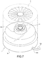
- FIG. 7 is an assembled view showing that the present invention is applied to a small night lamp.
- FIG. 8 is an assembled view showing that the present invention is applied to an electrical heater.
- FIG. 1 is a schematic view showing the external appearance of the present invention
- FIG. 2 is a cross-sectional view of the present invention.
- the present invention provides a multiple-function power supply adapter 1 that can be applied to various electrical appliances, such as a cigar-lighter, a small night lamp, an electrical heater or other electric devices.
- the power supply adapter 1 includes a supporting base 10 , a power-supplying sleeve 11 and a transforming unit 12 .
- the supporting base 10 is used to support each of the above-mentioned electrical appliances, so that the electrical appliance can be placed on a table or other locations via the supporting base 10 , thereby facilitating a user to use it nearby.
- the supporting base 10 has a profile similar to a disk base.
- the interior of the supporting base is hollowed out to allow the transforming unit 12 to be disposed therein.
- the interior of the supporting base 10 is provided with a winding disk 100 for winding and accommodating a power supply line 122 described later.
- the supporting base 10 is provided with an annular positioning portion 101 thereon.
- the positioning portion 101 is located substantially in the center of the top surface of the supporting base 10 for positioning the associated electrical appliance, so that the electrical appliance can be supported on the supporting base 10 firmly.
- the power-supplying sleeve 11 is a common automobile power-supplying socket, which is a commonly used and standardized component.
- the power-supplying sleeve 11 is provided upright in the positioning portion 101 of the supporting base 10 , so that the electricity can be delivered to the associated electrical appliance with a plug thereof being inserted into the power-supplying sleeve 11 .
- the positioning portion 101 is provided thereon with a transparent cover 102 for covering on the power-supplying sleeve 11 .
- the underside of the transparent cover 102 is provided with a plurality of light-emitting elements 103 around the periphery of the power-supplying sleeve 11 .
- Each of the light-emitting elements 103 can be a light-emitting diode (LED), so that the user can determine whether the electricity is supplied or not based on the lighting of the LED.
- LED light-emitting diode
- the transforming unit 12 is provided in the interior of the supporting base 10 , and is further located in the winding disk 100 .
- the transforming unit 12 comprises a circuit board 120 , a coil assembly 121 electrically connected to the circuit board 120 , and a plurality of capacitors provided on the circuit board 120 .
- Each of the capacitors is electrically connected with the power-supplying sleeve 11 and in turn the power supply line 122 via the circuit board 120 .
- the power supply line 122 extends from the inside of the supporting base 10 to the outside thereof, and is provided with a power supply plug 123 that is inserted into a household socket.
- the supporting base 10 is provided with a notch 104 for allowing the power supply line 122 to pass through, thereby avoiding from pressing and damaging the power supply line 122 when the supporting base 10 is positioned horizontally.
- the multiple-function power supply adapter of the present invention can be obtained.
- the power supply adapter 1 can be applied to an automobile cigar-lighter 2 .
- the power-supplying adapter 1 can heat the cigar-lighter 2 , so that the user can light up a cigarette by using the cigar-lighter.
- an ashtray 21 can straddle on the supporting base 10 .
- the center of the ashtray 21 is provided with a hole 210 for allowing the positioning portion 101 of the supporting base 10 to be inserted therein. In this way, the present invention can be used in a situation that a smoker is allowed to light up a cigarette and cast the cigarette ash or the cigarette butt.
- the power supply adapter 1 is applied to a small night lamp 3 .
- the small night lamp 3 With a power supply plug 30 of the small night lamp 3 being inserted into the power-supplying sleeve 11 , the small night lamp 3 can be disposed on any plane such as a table without being limited to a wall corner.
- the power supply adapter 1 is applied to an electrical heater 4 .
- the electrical heater 4 can be mounted on the power supply adapter 1 .
- the power supply adapter 1 can be applied to various electrical appliances.
- the present invention achieves the desired objects and solves the drawbacks of prior art. Further, the present invention has novelty and inventive steps and thus conforms to the requirement for a utility model patent.
Abstract
A multiple-function power supply adapter includes a supporting base with an interior thereof hollowed out, a power-supplying sleeve provided on the supporting base, and a transforming unit provided in the supporting base. The power-supplying sleeve is an automobile power-supplying socket. The transforming unit is electrically connected between a power supply line and the power-supplying sleeve. The power supply line extends from the inside of the supporting base to the outside thereof. The distal end of the power supply line is provided with a power supply plug. With the automobile power-supplying sleeve, the power supply adapter can be applied to various electrical appliances.
Description
1. Field of the Invention
The present invention relates to an accessory of an electrical appliance, and in particular to a power supply adapter for an electrical appliance, which can be applied to various electrical appliances.
2. Description of Prior Art
The cigar-lighter commonly used in an automobile is lodged in a charging socket provided in the automobile so as to be heated by electricity. In this way, the cigar-lighter generates a high temperature to allow a user to light up a cigarette.
However, such a convenient cigar-lighter can be merely used in the automobile. If someone intends to light up a cigarette in a room, he/she still needs to use a lighter or the like which is not as rapid and convenient in operation as the automobile cigar-lighter because the lighter has to utilize liquefied gas to ignite a flame. Therefore, there is a possibility that the fuel may be used up and such a lighting operation is somewhat dangerous.
As for a common small night lamp, since it has to be inserted into a socket provided in a wall corner of a house, the illuminating region thereof will be limited by the location of the socket. Although an extension line can be used to extend the power supply, the socket of the extension line cannot be located firmly, so that it is not suitable to be arranged on a table or other locations.
According to the above, in order to solve the above-mentioned drawbacks, the inventor proposes the present invention based on his deliberate research.
The present invention is to provide a multiple-function power supply adapter, in which an automobile power-supplying socket is electrically connected to an automobile cigar-lighter, so that the automobile cigar-lighter can be disposed on a table or the like for use without being limited to an automobile only.
The present invention is to provide a multiple-function power supply adapter. With the above-mentioned automobile power-supplying socket, the electricity can be supplied to various electrical appliances such as a small night lamp, electrical heater or the like, so that those electrical appliances can be disposed on a table or other locations without being limited to the socket in a wall corner.
The present invention is to provide a multiple-function power supply adapter, which includes a supporting base with an interior thereof hollowed out, a power-supplying sleeve provided on the supporting base, and a transforming unit provided in the supporting base. The power-supplying sleeve is an automobile power-supplying socket. The transforming unit is electrically connected between a power supply line and the power-supplying sleeve. The power supply line extends from the inside of the supporting base to the outside thereof. The distal end of the power supply line is provided with a power supply plug. Via the above arrangement, the power supply adapter can be obtained.
In order to make the Examiner to further understand the characteristics and technical contents of the present invention, a detailed description relating thereto will be made with reference to the accompanying drawings. However, it should be understood that the drawings are illustrative only but not to limit the present invention.
The supporting base 10 is used to support each of the above-mentioned electrical appliances, so that the electrical appliance can be placed on a table or other locations via the supporting base 10, thereby facilitating a user to use it nearby. In the illustrated embodiment of the present invention, the supporting base 10 has a profile similar to a disk base. The interior of the supporting base is hollowed out to allow the transforming unit 12 to be disposed therein. The interior of the supporting base 10 is provided with a winding disk 100 for winding and accommodating a power supply line 122 described later. The supporting base 10 is provided with an annular positioning portion 101 thereon. The positioning portion 101 is located substantially in the center of the top surface of the supporting base 10 for positioning the associated electrical appliance, so that the electrical appliance can be supported on the supporting base 10 firmly.
The power-supplying sleeve 11 is a common automobile power-supplying socket, which is a commonly used and standardized component. The power-supplying sleeve 11 is provided upright in the positioning portion 101 of the supporting base 10, so that the electricity can be delivered to the associated electrical appliance with a plug thereof being inserted into the power-supplying sleeve 11. Further, the positioning portion 101 is provided thereon with a transparent cover 102 for covering on the power-supplying sleeve 11. The underside of the transparent cover 102 is provided with a plurality of light-emitting elements 103 around the periphery of the power-supplying sleeve 11. Each of the light-emitting elements 103 can be a light-emitting diode (LED), so that the user can determine whether the electricity is supplied or not based on the lighting of the LED.
The transforming unit 12 is provided in the interior of the supporting base 10, and is further located in the winding disk 100. The transforming unit 12 comprises a circuit board 120, a coil assembly 121 electrically connected to the circuit board 120, and a plurality of capacitors provided on the circuit board 120. Each of the capacitors is electrically connected with the power-supplying sleeve 11 and in turn the power supply line 122 via the circuit board 120. The power supply line 122 extends from the inside of the supporting base 10 to the outside thereof, and is provided with a power supply plug 123 that is inserted into a household socket. With the transforming unit 12 lowering the household voltage 110V to a voltage of 12V, each of the above-mentioned electrical appliances can be used. Since the principle of voltage transformation belongs to prior art and is not within the claimed scope of the present invention, the description thereof is omitted.
In order to facilitate the power supply line 122 to extend from the interior of the supporting base 10, the supporting base 10 is provided with a notch 104 for allowing the power supply line 122 to pass through, thereby avoiding from pressing and damaging the power supply line 122 when the supporting base 10 is positioned horizontally.
Therefore, with the above structural constitution, the multiple-function power supply adapter of the present invention can be obtained.
With reference to FIGS. 3 and 4 , the power supply adapter 1 can be applied to an automobile cigar-lighter 2. With a plug 20 of the cigar-lighter 2 being inserted into the power-supplying sleeve 11, the power-supplying adapter 1 can heat the cigar-lighter 2, so that the user can light up a cigarette by using the cigar-lighter. Further, as shown in FIG. 5 , when using the cigar-lighter 2, an ashtray 21 can straddle on the supporting base 10. The center of the ashtray 21 is provided with a hole 210 for allowing the positioning portion 101 of the supporting base 10 to be inserted therein. In this way, the present invention can be used in a situation that a smoker is allowed to light up a cigarette and cast the cigarette ash or the cigarette butt.
As shown in FIGS. 6 and 7 , the power supply adapter 1 is applied to a small night lamp 3. With a power supply plug 30 of the small night lamp 3 being inserted into the power-supplying sleeve 11, the small night lamp 3 can be disposed on any plane such as a table without being limited to a wall corner.
Further, as shown in FIG. 8 , the power supply adapter 1 is applied to an electrical heater 4. Via the above-mentioned manner, the electrical heater 4 can be mounted on the power supply adapter 1. Of course, with a suitable plug of the other electrical appliance being inserted into the automobile power-supplying socket, the power supply adapter 1 can be applied to various electrical appliances.
According to the above, the present invention achieves the desired objects and solves the drawbacks of prior art. Further, the present invention has novelty and inventive steps and thus conforms to the requirement for a utility model patent.
Although the present invention has been described with reference to the foregoing preferred embodiments, it will be understood that the invention is not limited to the details thereof. Various equivalent variations and modifications can still occur to those skilled in this art in view of the teachings of the present invention. Thus, all such variations and equivalent modifications are also embraced within the scope of the invention as defined in the appended claims.
Claims (13)
1. A multiple-function power supply adapter, comprising:
a supporting base with a hollow interior;
a power-supplying sleeve being an automobile power-supplying socket and provided in the hollow interior of the supporting base; and
a transforming unit provided in the supporting base and electrically connected between a power supply line and the power-supplying sleeve, the power supply line extending from inside of the supporting base to outside thereof, a distal end of the power supply line being provided with a power supply plug.
2. The multiple-function power supply adapter according to claim 1 , wherein the supporting base has a profile of a disk base.
3. The multiple-function power supply adapter according to claim 1 , wherein the interior of the supporting base is provided with a winding disk for winding and accommodating the power supply line.
4. The multiple-function power supply adapter according to claim 1 , wherein the supporting base is provided thereon with a positioning portion for allowing an associated electrical appliance to be disposed on the supporting base.
5. The multiple-function power supply adapter according to claim 1 , wherein the supporting base is provided with light-emitting elements to allow a user to determine whether the electricity is supplied based on the lighting of the light-emitting element.
6. The multiple-function power supply adapter according to claim 5 , wherein the light-emitting element is a light-emitting diode.
7. The multiple-function power supply adapter according to claim 5 , wherein a plurality of light-emitting elements are provided on the periphery of the power-supplying sleeve.
8. The multiple-function power supply adapter according to claim 7 , wherein a transparent cover is provided on the light-emitting element.
9. The multiple-function power supply adapter according to claim 1 , wherein the supporting base is provided with a notch for allowing the power supply line to pass through.
10. The multiple-function power supply adapter according to claim 1 , further comprising an automobile cigar-lighter to be engaged in the power-supplying sleeve.
11. The multiple-function power supply adapter according to claim 10 , further comprising an ashtray installed on the supporting base.
12. The multiple-function power supply adapter according to claim 1 , wherein the multiple-function power supply adapter is applied to a small night lamp.
13. The multiple-function power supply adapter according to claim 1 , wherein the multiple-function power supply adapter is applied to an electrical heater.
Priority Applications (1)
| Application Number | Priority Date | Filing Date | Title |
|---|---|---|---|
| US11/933,510 US7510446B1 (en) | 2007-11-01 | 2007-11-01 | Multiple-function power supply adapter |
Applications Claiming Priority (1)
| Application Number | Priority Date | Filing Date | Title |
|---|---|---|---|
| US11/933,510 US7510446B1 (en) | 2007-11-01 | 2007-11-01 | Multiple-function power supply adapter |
Publications (1)
| Publication Number | Publication Date |
|---|---|
| US7510446B1 true US7510446B1 (en) | 2009-03-31 |
Family
ID=40474011
Family Applications (1)
| Application Number | Title | Priority Date | Filing Date |
|---|---|---|---|
| US11/933,510 Expired - Fee Related US7510446B1 (en) | 2007-11-01 | 2007-11-01 | Multiple-function power supply adapter |
Country Status (1)
| Country | Link |
|---|---|
| US (1) | US7510446B1 (en) |
Cited By (9)
| Publication number | Priority date | Publication date | Assignee | Title |
|---|---|---|---|---|
| US20130003369A1 (en) * | 2010-03-12 | 2013-01-03 | Jun Hiraoka | Lighting apparatus |
| USD761733S1 (en) | 2014-09-12 | 2016-07-19 | Steelcase Inc. | Electrical hub |
| USD762177S1 (en) | 2014-09-12 | 2016-07-26 | Steelcase Inc. | Electrical hub |
| US10333284B2 (en) | 2014-09-12 | 2019-06-25 | Steelcase Inc. | Floor power distribution system |
| USD883210S1 (en) * | 2017-10-10 | 2020-05-05 | Miki Pulley Co., Ltd. | Power transmission coupling |
| USD883211S1 (en) * | 2017-10-10 | 2020-05-05 | Miki Pulley Co., Ltd. | Power transmission coupling |
| USD883205S1 (en) * | 2018-05-16 | 2020-05-05 | Wanliang Xie | Power converter hub |
| USD884627S1 (en) * | 2018-05-11 | 2020-05-19 | Dell Products L.P. | Power adapter |
| CN112290323A (en) * | 2020-10-27 | 2021-01-29 | 惠州市国澳通科技有限公司 | Portable power cord and power adapter |
Citations (3)
| Publication number | Priority date | Publication date | Assignee | Title |
|---|---|---|---|---|
| US5564943A (en) * | 1995-05-26 | 1996-10-15 | Weiss; Alan | Electric socket convertor |
| US6994592B1 (en) * | 2004-08-27 | 2006-02-07 | Hop-On Wireless, Inc. | Universal charging apparatus |
| US20070238350A1 (en) * | 2006-04-05 | 2007-10-11 | Elliot Azoulay | Electrical adapter |
-
2007
- 2007-11-01 US US11/933,510 patent/US7510446B1/en not_active Expired - Fee Related
Patent Citations (3)
| Publication number | Priority date | Publication date | Assignee | Title |
|---|---|---|---|---|
| US5564943A (en) * | 1995-05-26 | 1996-10-15 | Weiss; Alan | Electric socket convertor |
| US6994592B1 (en) * | 2004-08-27 | 2006-02-07 | Hop-On Wireless, Inc. | Universal charging apparatus |
| US20070238350A1 (en) * | 2006-04-05 | 2007-10-11 | Elliot Azoulay | Electrical adapter |
Cited By (13)
| Publication number | Priority date | Publication date | Assignee | Title |
|---|---|---|---|---|
| US20130003369A1 (en) * | 2010-03-12 | 2013-01-03 | Jun Hiraoka | Lighting apparatus |
| US11063411B2 (en) | 2014-09-12 | 2021-07-13 | Steelcase Inc. | Floor power distribution system |
| USD761733S1 (en) | 2014-09-12 | 2016-07-19 | Steelcase Inc. | Electrical hub |
| USD762177S1 (en) | 2014-09-12 | 2016-07-26 | Steelcase Inc. | Electrical hub |
| US10333284B2 (en) | 2014-09-12 | 2019-06-25 | Steelcase Inc. | Floor power distribution system |
| US10516255B2 (en) | 2014-09-12 | 2019-12-24 | Steelcase Inc. | Floor power distribution system |
| US11594865B2 (en) | 2014-09-12 | 2023-02-28 | Steelcase Inc. | Floor power distribution system |
| USD883211S1 (en) * | 2017-10-10 | 2020-05-05 | Miki Pulley Co., Ltd. | Power transmission coupling |
| USD883210S1 (en) * | 2017-10-10 | 2020-05-05 | Miki Pulley Co., Ltd. | Power transmission coupling |
| USD884627S1 (en) * | 2018-05-11 | 2020-05-19 | Dell Products L.P. | Power adapter |
| USD883205S1 (en) * | 2018-05-16 | 2020-05-05 | Wanliang Xie | Power converter hub |
| CN112290323A (en) * | 2020-10-27 | 2021-01-29 | 惠州市国澳通科技有限公司 | Portable power cord and power adapter |
| CN112290323B (en) * | 2020-10-27 | 2021-12-10 | 惠州市国澳通科技有限公司 | Portable power cord and power adapter |
Similar Documents
| Publication | Publication Date | Title |
|---|---|---|
| US7510446B1 (en) | Multiple-function power supply adapter | |
| US9775925B2 (en) | Scent warmers and related methods | |
| TWI571274B (en) | Electrical lighting and heating modules, assemblies and scent warmers comprising such modules, and related methods | |
| US20080158863A1 (en) | Electrical Candle with Micro-Control Means | |
| KR101788310B1 (en) | Aroma candle container with lighting equipment using self-generation | |
| US10928059B2 (en) | Smart candle platform and system | |
| WO2014210591A1 (en) | Portable stove | |
| US11378272B2 (en) | Smart candle platform and system | |
| US20230175688A1 (en) | Smart candle platform and system | |
| CN201100930Y (en) | Multi-purpose power conversion device | |
| US20080247156A1 (en) | Illumination apparatus | |
| US20080310173A1 (en) | Candle cover apparatus | |
| TWM596625U (en) | Multi-purpose electronic incense burner | |
| JP3139503U (en) | Multipurpose power supply connection device | |
| CN105987404A (en) | Gas appliance | |
| KR200404498Y1 (en) | Stand type mood flashlight | |
| AU2019240389B2 (en) | Smart candle platform and system | |
| EP3942231B1 (en) | Smart candle platform | |
| CN211884690U (en) | Charcoal-fired luminous incense burner | |
| CN104235806B (en) | From lighting musical type lamp pinnacle jewelry | |
| JP3123968U (en) | Warming machine | |
| US9512986B2 (en) | Non-combustible candle apparatus for use in indoor and outdoor settings | |
| CN201007460Y (en) | Nightlight type switch base | |
| EP3977011A1 (en) | Smart candle platform and system | |
| TWM345924U (en) | Lighting device |
Legal Events
| Date | Code | Title | Description |
|---|---|---|---|
| REMI | Maintenance fee reminder mailed | ||
| LAPS | Lapse for failure to pay maintenance fees | ||
| STCH | Information on status: patent discontinuation |
Free format text: PATENT EXPIRED DUE TO NONPAYMENT OF MAINTENANCE FEES UNDER 37 CFR 1.362 |
|
| FP | Lapsed due to failure to pay maintenance fee |
Effective date: 20130331 |