US7509828B2 - Tool for making enhanced heat transfer surfaces - Google Patents
Tool for making enhanced heat transfer surfaces Download PDFInfo
- Publication number
- US7509828B2 US7509828B2 US11/388,689 US38868906A US7509828B2 US 7509828 B2 US7509828 B2 US 7509828B2 US 38868906 A US38868906 A US 38868906A US 7509828 B2 US7509828 B2 US 7509828B2
- Authority
- US
- United States
- Prior art keywords
- tube
- rod
- tool
- protrusions
- holder
- Prior art date
- Legal status (The legal status is an assumption and is not a legal conclusion. Google has not performed a legal analysis and makes no representation as to the accuracy of the status listed.)
- Active, expires
Links
Images


Classifications
-
- F—MECHANICAL ENGINEERING; LIGHTING; HEATING; WEAPONS; BLASTING
- F28—HEAT EXCHANGE IN GENERAL
- F28F—DETAILS OF HEAT-EXCHANGE AND HEAT-TRANSFER APPARATUS, OF GENERAL APPLICATION
- F28F1/00—Tubular elements; Assemblies of tubular elements
- F28F1/10—Tubular elements and assemblies thereof with means for increasing heat-transfer area, e.g. with fins, with projections, with recesses
- F28F1/42—Tubular elements and assemblies thereof with means for increasing heat-transfer area, e.g. with fins, with projections, with recesses the means being both outside and inside the tubular element
-
- B—PERFORMING OPERATIONS; TRANSPORTING
- B21—MECHANICAL METAL-WORKING WITHOUT ESSENTIALLY REMOVING MATERIAL; PUNCHING METAL
- B21C—MANUFACTURE OF METAL SHEETS, WIRE, RODS, TUBES OR PROFILES, OTHERWISE THAN BY ROLLING; AUXILIARY OPERATIONS USED IN CONNECTION WITH METAL-WORKING WITHOUT ESSENTIALLY REMOVING MATERIAL
- B21C37/00—Manufacture of metal sheets, bars, wire, tubes or like semi-manufactured products, not otherwise provided for; Manufacture of tubes of special shape
- B21C37/06—Manufacture of metal sheets, bars, wire, tubes or like semi-manufactured products, not otherwise provided for; Manufacture of tubes of special shape of tubes or metal hoses; Combined procedures for making tubes, e.g. for making multi-wall tubes
- B21C37/15—Making tubes of special shape; Making tube fittings
- B21C37/156—Making tubes with wall irregularities
- B21C37/158—Protrusions, e.g. dimples
-
- B—PERFORMING OPERATIONS; TRANSPORTING
- B21—MECHANICAL METAL-WORKING WITHOUT ESSENTIALLY REMOVING MATERIAL; PUNCHING METAL
- B21C—MANUFACTURE OF METAL SHEETS, WIRE, RODS, TUBES OR PROFILES, OTHERWISE THAN BY ROLLING; AUXILIARY OPERATIONS USED IN CONNECTION WITH METAL-WORKING WITHOUT ESSENTIALLY REMOVING MATERIAL
- B21C37/00—Manufacture of metal sheets, bars, wire, tubes or like semi-manufactured products, not otherwise provided for; Manufacture of tubes of special shape
- B21C37/06—Manufacture of metal sheets, bars, wire, tubes or like semi-manufactured products, not otherwise provided for; Manufacture of tubes of special shape of tubes or metal hoses; Combined procedures for making tubes, e.g. for making multi-wall tubes
- B21C37/15—Making tubes of special shape; Making tube fittings
- B21C37/20—Making helical or similar guides in or on tubes without removing material, e.g. by drawing same over mandrels, by pushing same through dies ; Making tubes with angled walls, ribbed tubes and tubes with decorated walls
-
- B—PERFORMING OPERATIONS; TRANSPORTING
- B21—MECHANICAL METAL-WORKING WITHOUT ESSENTIALLY REMOVING MATERIAL; PUNCHING METAL
- B21D—WORKING OR PROCESSING OF SHEET METAL OR METAL TUBES, RODS OR PROFILES WITHOUT ESSENTIALLY REMOVING MATERIAL; PUNCHING METAL
- B21D15/00—Corrugating tubes
- B21D15/04—Corrugating tubes transversely, e.g. helically
- B21D15/06—Corrugating tubes transversely, e.g. helically annularly
-
- B—PERFORMING OPERATIONS; TRANSPORTING
- B21—MECHANICAL METAL-WORKING WITHOUT ESSENTIALLY REMOVING MATERIAL; PUNCHING METAL
- B21J—FORGING; HAMMERING; PRESSING METAL; RIVETING; FORGE FURNACES
- B21J5/00—Methods for forging, hammering, or pressing; Special equipment or accessories therefor
- B21J5/06—Methods for forging, hammering, or pressing; Special equipment or accessories therefor for performing particular operations
- B21J5/068—Shaving, skiving or scarifying for forming lifted portions, e.g. slices or barbs, on the surface of the material
-
- B—PERFORMING OPERATIONS; TRANSPORTING
- B23—MACHINE TOOLS; METAL-WORKING NOT OTHERWISE PROVIDED FOR
- B23B—TURNING; BORING
- B23B29/00—Holders for non-rotary cutting tools; Boring bars or boring heads; Accessories for tool holders
- B23B29/03—Boring heads
- B23B29/034—Boring heads with tools moving radially, e.g. for making chamfers or undercuttings
- B23B29/03432—Boring heads with tools moving radially, e.g. for making chamfers or undercuttings radially adjustable during manufacturing
- B23B29/03446—Boring heads with tools moving radially, e.g. for making chamfers or undercuttings radially adjustable during manufacturing by means of inclined planes
- B23B29/03453—Grooving tool
-
- F—MECHANICAL ENGINEERING; LIGHTING; HEATING; WEAPONS; BLASTING
- F28—HEAT EXCHANGE IN GENERAL
- F28F—DETAILS OF HEAT-EXCHANGE AND HEAT-TRANSFER APPARATUS, OF GENERAL APPLICATION
- F28F1/00—Tubular elements; Assemblies of tubular elements
- F28F1/10—Tubular elements and assemblies thereof with means for increasing heat-transfer area, e.g. with fins, with projections, with recesses
- F28F1/42—Tubular elements and assemblies thereof with means for increasing heat-transfer area, e.g. with fins, with projections, with recesses the means being both outside and inside the tubular element
- F28F1/422—Tubular elements and assemblies thereof with means for increasing heat-transfer area, e.g. with fins, with projections, with recesses the means being both outside and inside the tubular element with outside means integral with the tubular element and inside means integral with the tubular element
-
- Y—GENERAL TAGGING OF NEW TECHNOLOGICAL DEVELOPMENTS; GENERAL TAGGING OF CROSS-SECTIONAL TECHNOLOGIES SPANNING OVER SEVERAL SECTIONS OF THE IPC; TECHNICAL SUBJECTS COVERED BY FORMER USPC CROSS-REFERENCE ART COLLECTIONS [XRACs] AND DIGESTS
- Y10—TECHNICAL SUBJECTS COVERED BY FORMER USPC
- Y10T—TECHNICAL SUBJECTS COVERED BY FORMER US CLASSIFICATION
- Y10T408/00—Cutting by use of rotating axially moving tool
- Y10T408/83—Tool-support with means to move Tool relative to tool-support
- Y10T408/85—Tool-support with means to move Tool relative to tool-support to move radially
-
- Y—GENERAL TAGGING OF NEW TECHNOLOGICAL DEVELOPMENTS; GENERAL TAGGING OF CROSS-SECTIONAL TECHNOLOGIES SPANNING OVER SEVERAL SECTIONS OF THE IPC; TECHNICAL SUBJECTS COVERED BY FORMER USPC CROSS-REFERENCE ART COLLECTIONS [XRACs] AND DIGESTS
- Y10—TECHNICAL SUBJECTS COVERED BY FORMER USPC
- Y10T—TECHNICAL SUBJECTS COVERED BY FORMER US CLASSIFICATION
- Y10T83/00—Cutting
- Y10T83/384—By tool inside hollow work
Definitions
- the invention relates generally to a tool and method for forming enhanced heat transfer surfaces.
- This invention relates to enhanced heat transfer surfaces, such as the surfaces (and particularly the inner surfaces) of heat transfer tubes, that facilitate heat transfer from one side of the surface to the other.
- Heat transfer tubes are commonly used in equipment, such as, for example, flooded evaporators, falling film evaporators, spray evaporators, absorption chillers, condensers, direct expansion coolers, and single phase coolers and heaters, used in the refrigeration, chemical, petrochemical, and food-processing industries.
- a variety of heat transfer mediums may be used in these applications, including, but not limited to, pure water, a water glycol mixture, any type of refrigerant (such as R-22, R-134a, R-123, etc.), ammonia, petrochemical fluids, and other mixtures.
- An ideal heat transfer tube would allow heat to flow completely uninhibited from the interior of the tube to the exterior of the tube and vice versa.
- free flow of heat across the tube is generally thwarted by the resistance to heat transfer.
- the overall resistance of the tube to heat transfer is calculated by adding the individual resistances from the outside to the inside of the tube or vice versa.
- tube manufacturers have striven to uncover ways to reduce the overall resistance of the tube.
- One such way is to enhance the outer surface of the tube, such as by forming fins on the outer surface. As a result of recent advances in enhancing the outer tube surface (see, e.g., U.S. Pat. Nos.
- the pattern, shapes and sizes of the grooves and ridges on the inner tube surface may be changed to further increase heat exchange performance.
- tube manufacturers have gone to great expense to experiment with alternative designs, including those disclosed in U.S. Pat. No. 5,791,405 to Takima et al., U.S. Pat. Nos. 5,332,034 and 5,458,191 to Chiang et al., and U.S. Pat. No. 5,975,196 to Gaffaney et al.
- heat transfer surfaces work by using the phase change of a liquid to absorb heat.
- heat transfer surfaces often incorporate a surface for enhancing boiling or evaporating. It is generally known that the heat transfer performance of a surface can be enhanced by increasing nucleation sites on the boiling surfaces, by inducing agitation near a single-phase heat transfer surface, or by increasing area and surface tension effects on condensation surfaces.
- One method for enhancing boiling or evaporating is to roughen the heat transfer surface by sintering, radiation-melting or edging methods to form a porous layer thereon. A heat transfer surface having such a porous layer is known to exhibit better heat transfer characteristics than that of a smooth surface.
- the voids or cells formed by the above-mentioned methods are small and impurities contained in the boiling liquid may clog them so that the heat transfer performance of the surface is impaired. Additionally, since the voids or cells formed are non-uniform in size or dimension, the heat transfer performance may vary along the surface. Furthermore, known heat transfer tubes incorporating boiling or evaporating surfaces often require multiple steps or passes with tools to create the final surface.
- the invention relates to a tool assembly that can be used to improve heat transfer surfaces, such as may be formed on a tube, and thereby enhance heat transfer performance of tubes used in at least all of the above-referenced applications (i.e., flooded evaporators, falling film evaporators, spray evaporators, absorption chillers, condensers, direct expansion coolers and single phase coolers and heaters, used in the refrigeration, chemical, petrochemical and food-processing industries).
- the tool assembly includes rods having tips shaped to form the desired surfaces and positioned in a tool holder.
- the tool assembly is configured so that, when in use, the tips extend from the tool holder to cut the tube surface but retract within the tool holder when cutting is complete. In this way, the tips are protected from chipping or dulling when not in use.
- the rods are preferably made of carbide. The strongest carbide is only available in rod form. Thus, with the rod configuration of the invention, the tips may be formed of the strongest available material for cutting. Different geometries can be imparted to the rod tips so as to create different surfaces. However, regardless of the geometry of the rod tips, the rod tips may be re-shaped multiple times before the rods must be replaced. This significantly reduces tooling and material costs. Moreover, the rods are removable from the tool assembly. Thus, when a tip becomes chipped or dull, the rod may be removed for re-shaping of its tip or replaced altogether.
- the tool assembly can be used to form a plurality of protrusions on the tube surface that significantly reduce tube side resistance and improve overall heat transfer performance.
- the protrusions create additional paths for fluid flow within the tube and thereby enhance turbulence of heat transfer mediums flowing within the tube. This increases fluid mixing to reduce the boundary layer build-up of the fluid medium close to the inner surface of the tube, such build-up increasing the resistance and thereby impeding heat transfer.
- the protrusions also provide extra surface area for additional heat exchange. Formation of the protrusions in accordance with this invention can result in the formation of up to five times more surface area along the inner surface of the tube than with simple ridges.
- the tool assembly may also be used to create a plurality of cavities that significantly decrease the transition time to move from one phase to the next, for example to move from single-phase to evaporation.
- the cavities result in thin film boiling within the cavity, and, given that the heat transfer coefficient is inversely proportional to the film thickness, thereby enhances heat transfer. Protrusions creating cavities also provide extra surface area for additional heat exchange.
- the method of this invention includes using the tool assembly, which can easily be added to existing manufacturing equipment, having a cutting tip to cut through ridges on the tube surface or directly into the tube surface to create layers and to lift the layers to form the protrusions.
- the protrusions are formed without removal of metal from the inner surface of the tube, thereby eliminating debris which can damage the equipment in which the tubes are used.
- the method may also include flattening or bending the tips of the protrusions.
- the grooves, protrusions and flattened tips on the tube surface can be formed in the same or a different operation.
- the tool assembly may be sued to enhance the inner or outer surface of a heat transfer tube or may be used on flat heat transfer surfaces, such as are used to cool micro-electronics. Such surfaces may be suitable in any number of applications, including, for example, applications for use in the HVAC, refrigeration, chemical, petrochemical and food processing industries.
- the physical geometries of the protrusions may be changed to tailor the tube to a particular application and fluid medium.
- FIG. 1 a is a fragmentary perspective view of the partially-formed inner surface of one embodiment of a tube of this invention.
- FIG. 1 b is a side elevation view of the tube shown in FIG. 1 a in the direction of arrow a.
- FIG. 1 c is a side elevation view similar to FIG. 1 b except that the protrusions protrude from the inner surface of the tube in a direction that is not perpendicular to tube axis S.
- FIG. 1 d is a front elevation view of the tube shown in FIG. 1 a in the direction of arrow b.
- FIG. 1 e is a top plan view of the tube shown in FIG. 1 a.
- FIG. 2 is a photomicrograph of an inner surface of one embodiment of a tube of this invention.
- FIG. 3 is a photomicrograph of an inner surface of an alternative embodiment of a tube of this invention.
- FIG. 4 is a side elevation view of one embodiment of the manufacturing equipment that can be used to produce tubes in accordance with this invention.
- FIG. 5 is a perspective view of the equipment of FIG. 4 .
- FIG. 6 a is a perspective view of one embodiment of the tool of this invention.
- FIG. 6 b is a side elevation view of the tool shown in FIG. 6 a.
- FIG. 6 c is a bottom plan view of the tool of FIG. 6 b.
- FIG. 6 d is a top plan view of the tool of FIG. 6 b.
- FIG. 7 a is a perspective view of an alternative embodiment of the tool of this invention.
- FIG. 7 b is a side elevation view of the tool shown in FIG. 7 a.
- FIG. 7 c is a bottom plan view of the tool of FIG. 7 b.
- FIG. 7 d is a top plan view of the tool of FIG. 7 b.
- FIG. 8 a is a fragmentary perspective view of the partially-formed inner surface of an alternative embodiment of a tube of this invention where the depth of the cut through the ridges is less than the ridge height.
- FIG. 8 b is a fragmentary perspective view of the partially-formed inner surface of an alternative embodiment of a tube of this invention where the depth of the cut through the ridges is greater than the ridge height.
- FIG. 9 a is a fragmentary top plan view of the inner surface of another embodiment of a tube in accordance with this invention.
- FIG. 9 b is an elevation view of the tube shown in FIG. 9 a in the direction of arrow 22 .
- FIG. 10 a is a fragmentary view of an inner surface of a tube of this invention, showing the tool approaching the ridge in direction g for cutting a protrusion from the ridge in direction g.
- FIG. 10 b is a fragmentary view of an alternative inner surface of a tube of this invention showing the tool approaching the ridge in direction g for cutting a protrusion from the ridge in direction g.
- FIG. 11 a is a schematic of the inner surface of a tube in accordance with this invention showing the angular orientation between the ridges and grooves, whereby the ridges and grooves are opposite hand helix.
- FIG. 11 b is a schematic of the inner surface of a tube in accordance with this invention showing the angular orientation between the ridges and grooves, whereby the ridges and grooves are same hand helix.
- FIG. 12 is a bar graph comparing the tube-side heat transfer coefficients of various tubes of the prior art and of tubes in accordance with this invention.
- FIG. 13 is bar graph comparing the overall heat transfer coefficients of various tubes of the prior art and of tubes in accordance with this invention.
- FIG. 14 is a fragmentary perspective view of a partially-formed boiling surface on the inner diameter of a heat transfer tube according to an embodiment of the invention.
- FIG. 15A is a fragmentary perspective view of the partially-formed boiling surface of the embodiment of FIG. 14 .
- FIG. 15B is a photomicrograph of a perspective view of the partially-formed boiling surface of FIG. 15A .
- FIG. 15C is a cross-sectional view of the partially-formed boiling surface of FIG. 15A .
- FIG. 16A is a fragmentary perspective view of a boiling surface on the inner diameter of a heat transfer tube according to an alternative embodiment of the invention.
- FIG. 16B is a cross-sectional view of the tube shown in FIG. 16A .
- FIG. 16C is a photomicrograph of a top plan view the boiling surface of FIG. 16A .
- FIG. 16D is a photomicrograph of a cross-section of the boiling surface of FIG. 16A .
- FIG. 17A is a fragmentary perspective view of a boiling surface on the inner diameter of a heat transfer tube according to an alternative embodiment of the invention.
- FIG. 17B is a cross-sectional view of the tube shown in FIG. 17A .
- FIG. 18A is a fragmentary perspective view of a boiling surface on the inner diameter of a heat transfer tube according to an alternative embodiment of the invention.
- FIG. 18B is a photomicrograph of a cross-section of the boiling surface of FIG. 18A .
- FIG. 18C is a cross-sectional view of the boiling surface of FIG. 18A .
- FIG. 19 is a perspective view of a grooving tool.
- FIG. 20A is perspective view of a tool according to another embodiment of the invention.
- FIG. 20B is a perspective view of a boiling surface formed by the tool of FIG. 20A .
- FIG. 20C is a photomicrograph of the boiling surface of FIG. 20B .
- FIG. 21 is a perspective view of an embodiment of the manufacturing equipment than can be used to produce heat transfer tubes in accordance with this invention.
- FIG. 22 is perspective view of a tool according to another embodiment of the invention.
- FIG. 23A is a cross-sectional view of a boiling surface on the inner diameter of a heat transfer tube in accordance with an alternative embodiment of the invention.
- FIG. 23B is a photomicrograph of the boiling surface of FIG. 23A .
- FIG. 24A is a cross-sectional view of a boiling surface as it is formed with a tool in accordance with an embodiment of the invention.
- FIG. 24B is a cross-sectional view of a boiling surface as it is formed with a tool in accordance with an alternative embodiment of the invention.
- FIG. 24C is a perspective view of a tool tip according to an embodiment of the invention that may be used to form the boiling surfaces of FIGS. 24A and 24B .
- FIG. 24D is an alternative perspective view of the tool tip shown in FIG. 24C .
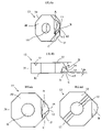
- FIG. 25 is a perspective view of an alternative tool embodiment of this invention with recessed tips.
- FIG. 26 is a perspective view of a the embodiment of FIG. 25 with exposed tips.
- FIG. 27 is a perspective view of a rod of the embodiment of FIGS. 25 and 26 .
- FIG. 28 is a perspective view of a rod guide of the embodiment of FIGS. 25 and 26 .
- FIG. 29 is an alternative perspective view of the rod guide of FIG. 28 .
- FIG. 30 is a perspective view of the rod of FIG. 27 positioned in the rod guide of FIGS. 28 and 29 .
- FIG. 31 is a perspective view of the rod of FIG. 27 positioned and secured in the rod guide of FIGS. 28 and 29 with a screw.
- FIG. 32 is a perspective view of the tool holder of the embodiment of FIGS. 25 and 26 .
- FIG. 33 is an alternative perspective view of the tool holder of FIG. 32 .
- FIG. 34 is a perspective view of the rod/rod guide assembly of FIGS. 30 and 31 positioned in the tool holder of FIGS. 32 and 33 .
- a tube in accordance with this invention is generally useful in, but not limited to, any application where heat needs to be transferred from one side of the tube to the other side of the tube, such as in multi-phase (both pure liquids or gases or liquid/gas mixtures) evaporators and condensers. While the following discussion provides desirable dimensions for a tube of this invention, the tubes of this invention are in no way intended to be limited to those dimensions. Rather, the desirable geometries of the tube will depend on many factors, not the least important of which are the properties of the fluid flowing through the tube. One skilled in the art would understand how to alter the geometry of the surfaces of the tube to maximize heat transfer used in various applications and with various fluids. Furthermore, although the drawings show the surface as it would be when found on the inner surface of a tube, it should be understood that the surface is suitable for use on the outer surface of a tube or on a flat surface, such as is used in micro-electronics.
- FIGS. 1 a - e show a partially-formed inner surface 18 of one embodiment of the tube 21 of this invention.
- Inner surface 18 includes a plurality of protrusions 2 .
- Protrusions 2 are formed from ridges 1 formed on inner surface 18 .
- Ridges 1 are first formed on inner surface 18 such as by, but not limited to, deforming, cutting, broaching, or extruding. The ridges 1 are then cut to create ridge layers 4 , which are subsequently lifted up to form protrusions 2 (best seen in FIGS. 1 a and 1 b ). This cutting and lifting can be, but does not have to be, accomplished using tool 13 , shown in FIGS. 6 a - d and 7 a - d , or tool assembly 510 , shown in FIGS. 25-34 , both of which are described below.
- Ridges 1 are formed on inner surface 18 at a helix angle ⁇ to the axis s of the tube (see FIGS. 1 a and 1 e ).
- Helix angle ⁇ may be any angle between 0°-90°, but preferably does not exceed 70°.
- the height e r of ridges 1 should generally be greater the more viscous the liquid flowing through tube 21 .
- a height e r of greater than zero (preferably, but not necessarily, at least 0.001 inches) up to 25% of the inside diameter of the tube (D i ) will generally be desirable in a tube sample used with highly viscous liquids at low temperatures.
- D i is the inside diameter of tube 21 measured from inner surface 18 of tube 21 .
- the axial pitch P a,r of ridges 1 depends on many factors, including helix angle a, the number of ridges 1 formed on inner surface 18 of tube 21 , and the inside diameter D i of tube 21 .
- the ratio of P a,r /e r is preferably at least 0.002, and the ratio of e r /D i is preferably between approximately 0.001-0.25. Again, however, one skilled in the art will readily understand that these preferred ratio values will often depend, at least in part, on the fluid medium used and operating conditions (e.g., the temperature of the fluid medium).
- Ridge layers 4 are cut at an angle ⁇ to axis s that is preferably between approximately 20°-50°, inclusive, and more preferably around 30°.
- the axial pitch P a,p of protrusions 2 may be any value greater than zero and generally will depend on, among other factors, the relative revolutions per minute between the tool (discussed below) and the tube during manufacture, the relative axial feed rate between the tool and the tube during manufacture, and the number of tips provided on the tool used to form the protrusions during manufacture. While the resulting protrusions 2 can have any thickness S p , the thickness S p is preferably approximately 20-100% of pitch P a,p .
- the height e p of protrusions 2 is dependent on the cutting depth t (as seen in FIGS.
- the height e p of protrusions 2 is preferably a value at least as great as the cutting depth t up to three times the cutting depth t. It is preferable, but not necessary, to form ridges 1 at a height e r and set the cutting angle ⁇ at a value that will result in the height e p of protrusions 2 being at least approximately double the height e r of ridges 1 .
- the ratio of e p /D i is preferably between approximately 0.002-0.5 (i.e., e p /D i is double the preferred range of the ratio e r /D i of approximately 0.001-0.25).
- FIGS. 1 a and 1 b show cutting depth t equal to the height e r of ridges 1 so that the base 40 of protrusion 2 is located on the inner surface 18 of tube 21 .
- the cutting depth t need not be equal to the ridge height e r , however. Rather, the ridges 1 can be cut only partially through ridges 1 (see FIG. 8 a ) or beyond the height of ridges 1 and into tube wall 3 (see FIG. 8 b ).
- the ridges 1 are not cut through their entire height e r so that the base 40 of protrusions 2 is positioned further from the inner surface 18 of tube 21 than the base 42 of ridges 1 , which is located on the inner surface 18 .
- FIG. 8 b illustrates a cutting depth t of beyond the ridge height e r , so that at least one wall of the protrusions 2 extends into tube wall 3 , beyond the inner surface 18 and ridge base 42 .
- grooves 20 are formed between adjacent protrusions 2 .
- Ridge layers 4 are cut and lifted so that grooves 20 are oriented on inner surface 18 at an angle ⁇ to the axis s of tube 21 (see FIGS. 1 e , 11 a , and 11 b ), which is preferably, but does not have to be, between approximately 80°-100°.
- protrusions 2 The shape of protrusions 2 is dependent on the shape of ridges 1 and the orientation of ridges 1 relative to the direction of movement of tool 13 .
- protrusions 2 In the embodiment of FIGS. 1 a - e , protrusions 2 have four side surfaces 25 , a sloped top surface 26 (which helps decrease resistance to heat transfer), and a substantially pointed tip 28 .
- the protrusions 2 of this invention are in no way intended to be limited to this illustrated embodiment, however, but rather can be formed in any shape. Moreover, protrusions 2 in tube 21 need not all be the same shape or have the same geometry.
- protrusions 2 Whether the orientation of protrusions 2 is straight (see FIG. 10 a ) or bent or twisted (see FIG. 10 b ) depends on the angle ⁇ formed between ridges 1 and the direction of movement g of tool 13 . If angle ⁇ is less than 90°, protrusions 2 will have a relatively straight orientation, such as is shown in FIG. 10 a . If angle ⁇ is more than 90°, protrusions 2 will have a more bent and/or twisted orientation, such as, for example, is shown in FIG. 10 b.
- Tool 13 may be used to cut through ridges 1 and lift the resulting ridge layers 4 to form protrusions 2 .
- Other devices and methods for forming protrusions 2 may be used, however.
- Tool 13 can be made from any material having the structural integrity to withstand metal cutting (e.g. steel, carbide, ceramic, etc.), but is preferably made of a carbide.
- the embodiments of the tool 13 shown in FIGS. 6 a - d and 7 a - d generally have a tool axis q, two base walls 30 , 32 and one or more side walls 34 .
- Aperture 16 is located through the tool 13 . Tips 12 are formed on side walls 34 of tool 13 .
- the tips can be mounted or formed on any structure that can support the tips in the desired orientation relative to the tube 21 and such structure is not limited to that disclosed in FIGS. 6 a - d and 7 a - d .
- the tips may be retractable within their supporting structure so that the number of tips used in the cutting process can easily be varied.
- FIGS. 6 a - d illustrate one embodiment of tool 13 having a single tip 12 .
- FIGS. 7 a - d illustrate an alternative embodiment of tool 13 having four tips 12 .
- tool 13 may be equipped with any number of tips 12 depending on the desired pitch P a,p of protrusions 2 .
- the geometry of each tip need not be the same for tips on a single tool 13 . Rather, tips 12 having different geometries to form protrusions having different shapes, orientations, and other geometries may be provided on tool 13 .
- Each tip 12 is formed by the intersection of planes A, B, and C.
- the intersection of planes A and B form cutting edge 14 that cuts through ridges 1 to form ridge layers 4 .
- Plane B is oriented at an angle ⁇ relative to a plane perpendicular to the tool axis q (see FIG. 6 b ).
- Angle ⁇ is defined as 90° ⁇ .
- angle ⁇ is preferably between approximately 40°-70° to allow cutting edge 14 to slice through ridges 1 at the desirable angle ⁇ between approximately 20°-50°.
- Angle ⁇ 1 defined by plane C and a plane perpendicular to tool axis q, determines the angle of inclination ⁇ (the angle between a plane perpendicular to the longitudinal axis s of tube 21 and the longitudinal axis of protrusions 2 (see FIG. 1 c )) at which protrusions 2 are lifted by lifting edge 15 .
- Angle ⁇ 1 angle ⁇ , and thus angle ⁇ 1 on tool 13 can be adjusted to directly impact the angle of inclination ⁇ of protrusions 2 .
- the angle of inclination ⁇ (and angle ⁇ 1 ) is preferably the absolute value of any angle between approximately ⁇ 45° to 45° relative to the plane perpendicular to the longitudinal axis s of tube 21 .
- protrusions can be aligned with the plane perpendicular to the longitudinal axis s of tube 21 (see FIG. 1 b ) or incline to the left and right relative to the plane perpendicular to the longitudinal axis s of tube 21 (see FIG. 1 c ).
- the tips 12 can be formed to have different geometries (i.e., angle ⁇ 1 may be different on different tips), and thus the protrusions 2 within tube 21 may incline at different angles (or not at all) and in different directions relative to the plane perpendicular to the longitudinal axis s of tube 21 .
- the physical dimensions of tool 13 may be modified to impact the physical dimensions of resulting protrusions 2 .
- FIGS. 4 and 5 illustrate one possible manufacturing set-up for enhancing the surfaces of tube 21 .
- These figures are in no way intended to limit the process by which tubes in accordance with this invention are manufactured, but rather any tube manufacturing process using any suitable equipment or configuration of equipment may be used.
- the tubes of this invention may be made from a variety of materials possessing suitable physical properties including structural integrity, malleability, and plasticity, such as, for example, copper and copper alloys, aluminum and aluminum alloys, brass, titanium, steel, and stainless steel.
- FIGS. 4 and 5 illustrate three arbors 10 operating on tube 21 to enhance the outer surface of tube 21 . Note that one of the arbors 10 has been omitted from FIG. 4 .
- Each arbor 10 includes a tool set-up having finning disks 7 which radially extrude from one to multiple start outside fins 6 having axial pitch P a,o .
- the tool set-up may include additional disks, such as notching or flattening disks, to further enhance the outer surface of tube 21 .
- additional disks such as notching or flattening disks, to further enhance the outer surface of tube 21 .
- fewer or more arbors may be used depending on the desired outer surface enhancements. Note, however, that depending on the tube application, enhancements need not be provided on the outer surface of tube 21 at all.
- a mandrel shaft 11 onto which mandrel 9 is rotatably mounted extends into tube 21 .
- Tool 13 is mounted onto shaft 11 through aperture 16 .
- Bolt 24 secures tool 13 in place.
- Tool 13 is preferably locked in rotation with shaft 11 by any suitable means.
- FIGS. 6 d and 7 d illustrate a key groove 17 that may be provided on tool 13 to interlock with a protrusion on shaft 11 (not shown) to fix tool 13 in place relative to shaft 11 .
- tube 21 In operation, tube 21 generally rotates as it moves through the manufacturing process. Tube wall 3 moves between mandrel 9 and finning disks 7 , which exert pressure on tube wall 3 . Under pressure, the metal of tube wall 3 flows into the grooves between the finning disks 7 to form fins 6 on the exterior surface of tube 21 .
- a desirable inner surface pattern includes ridges 1 , as shown in FIGS. 1 a and 4 .
- tube 21 encounters tool 13 positioned adjacent and downstream mandrel 9 .
- the cutting edge(s) 14 of tool 13 cuts through ridges 1 to form ridge layers 4 .
- Lifting edge(s) 15 of tool 13 then lift ridge layers 4 to form protrusions 2 .
- protrusions 2 are formed simultaneously with outside finning and tool 13 is fixed (i.e., not rotating or moving axially), tube 21 automatically rotates and has an axial movement.
- the axial pitch of protrusions P a,p is governed by the following formula:
- tool 13 can also be rotated. Both tube 21 and tool 13 can rotate in the same direction or, alternatively, both tube 21 and tool 13 can rotate, but in opposite directions.
- the necessary rotation (in revolutions per minute (RPM)) of the tool 13 can be calculated using the following formula:
- RPM tool RPM tube ⁇ ( P a , o ⁇ Z o - P a , p ⁇ Z i ) Z i ⁇ P a , p
- tool 13 should rotate in the same direction of tube 21 to obtain the desired pitch P a,p .
- tool 13 should rotate in the opposite direction of tube 21 to obtain the desired pitch P a,p .
- protrusions 2 may be produced in a separate operation from firming using a tube with pre-formed inner ridges 1 . This would generally require an assembly to rotate tool 13 or tube 21 and to move tool 13 or tube 21 along the tube axis. Moreover, a support is preferably provided to center tool 13 relative to the inner tube surface 18 .
- This formula is suitable when (1) the tube moves only axially (i.e., does not rotate) and the tool only rotates (i.e., does not move axially); (2) the tube only rotates and the tool moves only axially; (3) the tool rotates and moves axially but the tube is both rotationally and axially fixed; (4) the tube rotates and moves axially but the tool is both rotationally and axially fixed; and (5) any combination of the above.
- FIG. 9 a illustrates these additional paths 22 for fluid travel through tube 21 . These paths 22 are in addition to fluid flow paths 23 created between ridges 1 . These additional paths 22 have a helix angle ⁇ 1 relative to the tube axis s. Angle ⁇ 1 is the angle between protrusions 2 formed from adjacent ridges 1 . FIG. 9 b clearly shows these additional paths 22 formed between protrusions 2 . Helix angle ⁇ 1 , and thus orientation of paths 22 through tube 21 , can be adjusted by adjusting pitch P a,p of protrusions 2 using the following expression
- ridge helix angle ⁇ and angle ⁇ of grooves 20 are both either right hand or left hand helix (see FIG. 11 b ), then the “[ ⁇ ]” should be used in the above expression.
- ridge helix angle ⁇ and angle ⁇ of grooves 20 are opposite hand helix (see FIG. 11 a ), then the “[+]” should be used in the above expression.
- FIGS. 12 and 13 graphically illustrate the enhanced performance of two examples of such tubes (boiling tubes Tube No. 25 and Tube No. 14) by demonstrating the differences in the enhancement factors between these tubes.
- the enhancement factor is the factor by which the heat transfer coefficients (both tube-side (see FIG. 12 ) and overall (see FIG. 13 )) of these new tubes (Tube No. 25 and Tube No. 14) increase over existing tubes (Turbo-B®, Turbo-BII®, and Turbo B-III®).
- Tube Nos. 25 and 14 are merely examples of tubes in accordance with this invention.
- Other types of tubes made in accordance with this invention outperform existing tubes in a variety of applications.
- Tube No. 25 Tube No. 14 Protrusion Height 0.014 0.030 e p (inches) Protrusion Axial Pitch 0.0167 0.0144 P a,p (inches) Protrusion Thickness 0.0083 0.007 S p (inches) Depth of Cut into Ridge 0.007 0.015 t (inches) Moreover, the tool used to form the protrusions on Tube Nos. 25 and 14 had the following characteristics:
- FIG. 12 shows that the tube-side heat transfer coefficient of Tube No. 14 is approximately 1.8 times and Tube No. 25 is approximately 1.3 times that of Turbo B-III®, which is currently the most popular tube used in evaporator applications and shown as a baseline in FIGS. 12 and 13 .
- FIG. 13 shows that the overall heat transfer coefficient of Tube No. 25 is approximately 1.25 times and Tube No. 14 is approximately 1.5 times that of Turbo B-III.
- other embodiments of the invention include heat transfer surfaces with primary grooves 108 on the inner surface 104 of tube 100 , also having an outer surface 106 and tube wall 102 .
- the number of primary grooves 108 may vary depending on the application in which the heat transfer surface is to be used and depending on the fluid medium used.
- Primary grooves 108 may be formed by any method including, but not limited to, cutting, deforming, broaching or extrusion.
- Primary grooves 108 are formed on inner surface 104 at a helix angle ⁇ (not shown) to the axis s of the tube 100 .
- Helix angle a may be any angle between 0° and 90°, but preferably does not exceed 70°.
- the preferred helix angle a will often depend, at least in part, on the fluid medium used.
- the axial pitch of the primary grooves 108 depends on many factors, including helix angle ⁇ , the number of primary grooves 108 formed on inner surface 104 of tube 100 , and the inside diameter of tube 100 .
- the inside diameter is measured from inner surface 104 of tube 100 .
- An axial pitch of 0.01 inch to infinity (if the primary grooves 108 extend parallel to the tube axis s) is preferable.
- Protrusions 110 may be cut and lifted from inner surface 104 , as shown in FIGS. 15A-C .
- Protrusions 110 are preferably cut at an angle ⁇ to axis s to tube 100 (see FIG. 15C ).
- the height e p of protrusions 110 is dependent on the cutting depth t and angle ⁇ at which inner surface 104 is cut.
- the height e p of protrusions 110 is always a value greater than the cutting depth t.
- the cutting depth t is greater than the depth of primary grooves 108 .
- the cutting depth t may be less than or equal to the depth of primary grooves 108 as well.
- the axial pitch P a,p of protrusions 110 may be any value greater than zero and generally will depend on, among other factors, the relative revolutions per minute between the tool used to form the protrusions 110 (such as tool 13 discussed above or modified tools 300 , 325 , and 350 , or retractable tool assembly 510 , described below) and the tube 100 during manufacture, the relative axial feed rate between the tool used to form the protrusions 110 and the tube 100 during manufacture, and the number of cutting tips provided on the tool used to form the protrusions 110 during manufacture.
- protrusions 110 have an axial pitch P a,p of between 0.00197-0.197 inches.
- the axial pitch P a,p and height will generally depend on the number of protrusions, which height e p decreases as P a,p decreases.
- protrusions 110 are dependent on the shape of inner surface 104 and the orientation of inner surface 104 after primary grooves 108 have been cut relative to the direction of movement of the tool used to form the protrusions 110 .
- protrusions 110 have four side surfaces 120 , a sloped top surface 122 , and a substantially pointed tip 124 .
- the tips 124 of protrusions 110 optionally may be flattened to create boiling cavities 114 , as shown in FIGS. 16A-D .
- the tips 124 of protrusions 110 may be bent to create boiling cavities 114 , as shown in FIGS. 17A-B .
- the tips 124 of protrusions 110 may be thickened to create boiling cavities 114 , as shown in FIGS. 23A-B .
- the protrusions 110 may be angled toward each other, such as shown in FIGS. 18A-C , to create boiling cavities 114 .
- the tips 124 of protrusions 110 may remain substantially straight (not bent or flattened) and substantially perpendicular to the inner surface 104 of the tube 100 if a condensing surface is desired.
- the creation of boiling cavities 114 may substantially increase the efficacy of the boiling surface. The creation of boiling cavities 114 creates a path for fluid flow and increases the transition from liquid to vapor.
- protrusions 110 of this invention are in no way intended to be limited to the illustrated embodiment, however, but rather can be formed in any shape. Moreover, protrusions 110 in tube 100 need not be the same shape or have the same geometry.
- secondary grooves 112 may be located between adjacent protrusions 110 . Secondary grooves 112 are oriented at an angle ⁇ (not shown) to the axis s of tube 100 . Angle ⁇ may be any angle between approximately 80° and 100°. Preferably, angle ⁇ is approximately 90°.
- Certain embodiments of the invention also include methods and tools for making boiling surfaces on a tube.
- a grooving tool 200 such as that shown in FIG. 19 , is particularly useful in forming primary grooves 108 .
- Grooving tool 200 has an outer diameter greater than inner diameter of tube 100 so that when pulled or pushed through tube 100 , primary grooves 108 are formed.
- Grooving tool 200 also includes an aperture 202 for attaching to a shaft 130 (shown in FIG. 21 ).
- tool 13 may be modified to create a variety of different surfaces.
- the geometry of the tips on a single tool 13 need not be the same.
- FIG. 22 illustrates a modified tool 300 with two pairs of tips 318 , 320 having different geometries to create a boiling surface with inclined protrusions 110 , such as is shown in FIGS. 18A-C .
- the neighboring tips 318 , 320 are formed with different angles ⁇ 1 (which determines the angle of inclination ⁇ at which protrusions 110 are lifted).
- Changing the inclination angle (o of the protrusions 110 is possible to obtain a particular gap g between protrusions 120 at the opening 116 of the boiling cavity 114 , which affects the curved fluid flow s along the surface 104 .
- the tips 124 of protrusions 110 may be flattened or bent (such as shown in FIGS. 16A-D ) using flattening tool 400 , shown in FIG. 21 .
- the flattening tool 400 preferably has a diameter greater than the diameter of protrusions 110 on inner surface 104 .
- Flattening tool 400 includes an aperture 402 for attaching to shaft 130 .
- the tips 124 of protrusions 110 may achieve a shape similar to the flattened or bent tips 124 shown in FIGS. 16A-D without the use of a flattening tool 400 .
- tool 13 may be modified to incorporate, in addition to tips 12 that cut and lift protrusions, a tip or tips for flattening the tips 124 of protrusions 110 .
- modified tool 325 which is shown in FIG. 20A and which can otherwise have the same geometry as tool 13 , includes a flattening tip 316 which bends or flattens the protrusions after formation. Modified tool 325 may be used to create a boiling surface such as that shown in FIGS. 17A-B and 20 B-C.
- Boiling surfaces for use on heat transfer surfaces may also be achieved by creating protrusions 110 with thickened tips 124 .
- heat transfer surfaces with thickened tips 124 can be used to create boiling cavities 114 .
- FIGS. 24C-D illustrate a modified embodiment 350 of tool 13 that may be used to create protrusions 110 with thickened tips 124 .
- the tips 302 of modified tool 350 include two cutting edges 360 , 370 , a first cutting edge 360 oriented at an angle ⁇ 2 relative to a plane perpendicular to the tool axis q and a second cutting edge 370 oriented at an angle ⁇ 3 relative to a plane perpendicular to the tool axis q (angles ⁇ 2 and ⁇ 3 are analogous to angle ⁇ shown in FIG. 6 b ). Adjusting angles ⁇ 2 and ⁇ 3 adjusts the angle ⁇ at which the ridges 1 or tube surface 104 are cut and thus the resulting shape of the protrusion. By cutting into a ridge 1 or tube surface 104 at two angles, protrusions with a thinner shaft and thicker tip, as shown in FIGS. 23A-B and 24 A-B, can be formed.
- Protrusions 110 with thickened tips 124 can be obtained using the following formulas, with reference to FIGS. 24A-B :
- FIG. 21 illustrates one possible manufacturing set-up for enhancing the surfaces of tube 100 .
- the tubes 100 of this invention may be made from a variety of materials possessing suitable physical properties including structural integrity, malleability and plasticity, such as, for example, copper and copper alloys, aluminum and aluminum alloys, brass, titanium, steel and stainless steel.
- a shaft 130 onto which flattening tool 400 is mounted through aperture 402 , extends into tube 100 .
- Tool 13 is mounted onto shaft 130 through aperture 16 .
- modified tools 300 , 325 , or 350 may be substituted for tool 13 and/or flattening tool 400 removed, depending on the surface desired to be formed.
- Grooving tool 200 is rotatably mounted onto shaft 130 through aperture 202 .
- Bolt 132 secures all three tools 200 , 13 , 400 on the shaft 130 .
- the tools 13 and 400 are preferably locked in rotation with shaft 130 by any suitable means.
- FIGS. 6B and 7B illustrate a key groove 17 that may be provided on tool 13 to interlock with a protrusion on the shaft (not shown) to fix tool 13 into place relative to shaft 130 .
- the manufacturing set-up may include arbors that can be used to enhance the outer surface of tube, as discussed above and shown in FIG. 5 .
- Each arbor 10 generally includes a tool set-up having finning disks 7 which radially extrude from one to multiple start outside fins having axial pitch P a,o .
- the tool set-up may include additional disks, such as notching or flattening disks, to further enhance the outer surface of tube. Note, however, that depending on the tube application, enhancements need not be provided on outer surface of tube at all. In operation, tube wall moves between mandrel and the arbors, which exert pressure on tube wall.
- a desirable inner surface 104 includes primary grooves 108 , as shown in FIG. 14 . After formation of primary grooves 108 on inner surface 104 of tube 100 , tube 100 encounters tool 13 , positioned adjacent and downstream grooving tool 200 . The cutting edge(s) 14 of tool 13 cuts through inner surface 104 . Lifting edge(s) 15 of tool 13 then lifts inner surface 104 to form protrusions 1 10 .
- protrusions 110 are formed simultaneously with outside finning and tool 13 is fixed (i.e., not rotating or moving axially), tube 100 automatically rotates and has an axial movement.
- the axial pitch of protrusions 110 P a,p is governed by the following formula:
- tool 13 can also be rotated. Both tube 100 and tool 13 can rotate in the same direction or, alternatively, both tube 100 and tool 13 can rotate, but in opposite directions.
- the necessary rotation (in revolutions per minute (RPM)) of the tool 13 can be calculated using the following formula:
- RPM tool RPM tube ⁇ ( P a , o ⁇ Z o - P a , p ⁇ Z i ) Z i ⁇ P a , p
- tool 13 should rotate in the same direction of tube 100 to obtain the desired pitch P a,p .
- tool 13 should rotate in the opposite direction of tube 100 to obtain the desired pitch P a,p .
- protrusions 110 may be produced in a separate operation from primary grooves 108 by using a tube 100 with pre-formed primary grooves 108 . This would generally require an assembly to rotate tool 13 or tube 100 and to move tool 13 or tube 100 along the tube axis.
- a support (not shown) is preferably provided to center tool 13 relative to the inner tube surface 104 .
- This formula is suitable when (1) the tube 100 moves only axially (i.e., does not rotate) and the tool 13 only rotates (i.e., does not move axially); (2) the tube 100 only rotates and the tool 13 moves only axially; (3) the tool 13 rotates and moves axially but the tube 100 is both rotationally and axially fixed; (4) the tube 100 rotates and moves axially but the tool 13 is both rotationally and axially fixed; and (5) any combination of the above.
- FIG. 15A illustrates these additional paths for fluid travel through tube 100 . These paths are in addition to the fluid flow paths created between primary grooves 108 . These additional paths have a helix angle ⁇ 1 relative to the tube axis s. Angle ⁇ 1 is the angle between protrusions 110 formed from adjacent primary grooves 108 . Helix angle ⁇ 1 , and thus orientation of these additional paths through tube 100 , can be adjusted by adjusting pitch P a,p of protrusions 110 using the following expression
- FIGS. 25-34 illustrate another tool assembly 510 that can be used to form the heat transfer surfaces described above.
- Tool assembly includes a rod 512 having a tip 514 (see FIG. 27 ) for forming protrusions on the surface (and particularly the inner surface) of a heat transfer tube.
- the rod 512 may be of any material having the structural integrity to withstand metal cutting (e.g., steel, carbide, ceramic, etc.), but is preferably made of a carbide (such as tungsten carbide).
- the tip 514 is preferably, but does not have to be, formed integrally on an end of the rod 512 .
- the geometry of the tip 514 is preferably, but does not have to be, the same as the tips 12 of tool 13 , as shown in, and described above with respect to, FIGS. 6 a - d.
- the rod 512 is slid into a rod guide 516 (shown in FIGS. 28-29 ) having a head end 518 and a tail end 520 and provided with a shaft 522 dimensioned to receive the rod 512 (see FIGS. 30-31 ).
- the shaft 522 preferably extends through the rod guide 516 so as to have an opening at or proximal to both the head end 518 and the tail end 520 of the rod guide 516 .
- the tip 514 extends from the shaft 522 opening at the head end 518 of the rod guide 516 .
- a second screw 528 may be inserted in a screw hole 530 (shown in FIGS. 30-31 at the head end 518 of the rod guide 516 ) provided along the length of the rod guide 516 . This second screw 528 locks the rod 512 (and thus the tip 514 extension) in place relative to the rod guide 516 .
- the head end 518 of the rod guide 516 is preferably provided with a centering plane 532 .
- the centering plane 532 contacts the tops of the ridges 1 or the inner surface 104 of the tube to be cut by the cutting tip 514 . Through such contact, the centering plane 532 keeps the tool assembly 510 centered within the tube during inner surface enhancement.
- the rod guide 516 is then inserted into a tool holder 534 , best seen in FIGS. 32-33 .
- the tool holder 534 includes a head portion 536 and a rod portion 544 that defines the tool holder longitudinal axis (not shown).
- the head portion 536 has an outer wall 542 (shown as being cylindrical but that can be of any suitable shape) and is provided with hollow shafts 546 that extend substantially through the length of the head portion 536 .
- Each shaft 546 preferably has an opening at or near the top wall 540 of the head portion 536 and at or near the bottom wall 538 of the head portion 536 .
- each shaft 546 is positioned at an angle of preferably 0° to 90°, inclusive, with the longitudinal axis of the tool holder 534 .
- Shafts 546 are dimensioned to receive a rod guide 516 (with rod 512 ), which is slid into a shaft 546 on the tool holder 534 , as shown in FIG. 34 .
- the tool holder 534 may be provided with any number of hollow shafts 546 depending on the number of tips 514 desired to be used in a particular application. Depending on the desired pitch (P a,p ) of the ridge protrusions, not all of the hollow shafts 546 need be occupied with a rod guide 516 and rod 512 . Moreover, the geometry of the tips 514 on the rods 512 provided in a tool holder 534 need not be the same. Rather, tips 514 having different geometries to form protrusions having different shapes, orientations, and other geometries may be provided in the tool holder 534 . For example, as explained above with respect to FIGS.
- tool assembly 510 may be used to create a boiling surface with inclined protrusions as shown in FIGS. 18A-C .
- protrusions with thickened tips 124 may be formed to create nucleate boiling cavities.
- a washer 548 and a mandrel 550 are threaded onto the rod portion 544 of the tool holder 534 .
- the washer 548 includes a base 552 from which a plurality of prongs 554 extend.
- the prongs 554 of the washer 548 are positioned facing the bottom wall 538 of the head portion 536 of the tool holder 534 .
- the top wall 540 of the head portion 536 of the tool holder 534 is preferably provided with a threaded hole 556 in which a rod 558 is screwed.
- a sizing spacer 560 (mounted on the rod 558 ) is positioned adjacent the head portion 536 of the tool holder 534 , and a biasing element (in this case spring 562 , also mounted on the rod 558 ) is positioned adjacent the sizing spacer 560 .
- the biasing element may be any structure (including, but not limited to, a spring, including a flat spring, disc spring, helical spring, coil spring, zigzag spring, etc.) and be made from any material capable of compressing and expanding (including, but not limited to, rubber, metal, plastic, etc.).
- a nut 564 is screwed on the end of the rod 558 to retain the spring 562 and sizing spacer 560 on the tool assembly 510 . Note that a screw having a head and a shaft (not shown) can easily be substituted for the rod 558 and nut 564 .
- each rod guide 516 When assembled, the head end 518 of each rod guide 516 contacts the sizing spacer 560 and the tail end 522 of each rod guide 516 contacts the base 552 of the washer 548 .
- the distal end of the rod portion 544 of the tool holder 534 is provided with threads 566 so that the tool assembly 510 can be screwed onto the end of a guide rod (which can be fixed or rotate) that, with the assembly shown in FIGS. 25-26 attached to it, extends through the inside of a tube to enhance the tube surface.
- tips 514 In an equilibrium state (shown in FIG. 25 ), tips 514 (fixed in rod guides 516 ) do not extend beyond the outer wall 542 of the head portion 536 of the tool holder 534 and thus are protected.
- the mandrel 550 forms ridges on the inner surface of a tube, which are in turn cut and lifted by tips 514 to form the desired protrusions.
- the mandrel 550 can be replaced with a grooving tool 200 (shown in FIG. 19 ) to form grooves 108 (instead of ridges 1 ) on the tube surface (assuming, of course, that a force is applied to the tool assembly 510 to effectuate exposure of the tips 514 from the tool holder 534 ). Tips 514 would then cut into tube wall 104 (instead of upstanding ridges 1 ) to form protrusions, as shown in FIG. 15A .
- the mandrel 550 (or grooving tool 200 ) bears against the washer 548 which in turn bears against the rod guides 516 .
- the rod guides 516 slide along their respective hollow shafts 546 of the tool holder 534 toward the sizing spacer 560 .
- the base 552 of the washer 548 exerts a force on the tail ends 520 of the rod guides 516 and pushes them along shafts 546 . In this way, the tips 514 are pushed beyond the outer wall 542 of the head portion 536 of the tool holder 534 (as shown in FIG.
- the height of the washer prongs 554 controls the amount by which the rod guides 516 (and thus the tips 514 ) are pushed relative to the tool holder 534 and thus impacts the amount by which the tips 514 are exposed and consequent resulting cutting depth (t) of the tips 514 into the tube surface.
- Washers 548 having different height prongs 554 may be easily substituted on the tool assembly 510 and used to accurately control how far the tips 514 will extend beyond the outer wall 542 of the head portion 536 of the tool holder 534 and the resulting cutting depth (t) of the tips 514 .
- the sizing spacer 560 which regulates the height of the protrusions cut by tips 514 .
- Protrusions that are too high are flattened by the sizing spacer 560 until they reach the specified height.
- the height of the protrusions may be easily adjusted by substituting spacers 560 having different diameters on the tool assembly 510 .
- the spacer 560 may also be used to flatten some or all of the resulting protrusions to form nucleate boiling cavities, such as shown in FIGS. 16A-D , 17 A-B, and 20 B-C.
- a rod 512 with a tip 514 having the geometry of flattening tip 316 may also be inserted into the tool holder. In this way, a rod tip (or tips) positioned in the tool holder may also perform the flattening function.
- the compressed spring 562 causes the assembly 510 to return to its equilibrium state (shown in FIG. 25 ), meaning that the spring 562 forces the sizing spacer 560 to push the rod guides 516 back until the sizing spacer 560 contacts the top wall 540 of the head portion 536 of the tool holder 534 . In this way, the rod guides 516 slide along shafts 546 to retract the tips 514 back within the outer wall 542 of the tool holder 534 .
- the washer 548 , tool holder 534 , rod guide 516 , and sizing spacer 560 should preferably be made from materials capable of retaining their structure when subjected to such forces.
- these components may be made from metal, including carbide, steel, etc.
- the tool assembly 510 To remove the tool assembly 510 , it need only be unscrewed from the guide rod (not shown) by unscrewing the distal end of the rod portion 544 of the tool holder 534 . However, oftentimes the tool assembly 510 will become firmly fixed on the guide rod and thus unscrewing can be difficult. The force required to unscrew the tool assembly 510 , if done by hand, can cause damage to the tool assembly 510 . Thus, it is preferable (but not required) to provide holes 568 in the outer wall 542 of the tool holder 534 . A device can be inserted into the holes 568 , and the tool assembly 510 unscrewed using torque.
- this tool assembly 510 results in a number of benefits. If a tip 514 on a rod 512 wears down, the rod 512 can easily be removed for reshaping or the entire rod 512 replaced.
- the rod 512 containing the worn tip 514 can be removed from the rod guide 516 by removing screw 524 or 528 from the rod guide 516 and sliding the rod 512 from the rod guide 516 .
- the entire rod guide 516 can be removed from the tool holder 534 . Either way, tip 514 on an existing rod 512 can be reshaped and returned to the rod guide 516 or a new rod 512 with a new tip 514 can be inserted into the rod guide 516 .
- tips 514 on the rods 512 can be re-shaped multiple times before the rods 512 must be replaced. This significantly reduces tooling and material costs.
- the tool assembly 510 can easily be used on tubes with different wall thicknesses by using washers 548 having different prong 554 heights to adjust how much the tips 514 protrude from the tool holder 534 during use and/or by adjusting how far the tips 514 extend from their respective rod guides 516 , as described above.
Abstract
Description
e p =t/sin(90−φ)
or, given that φ=90−θ,
e p =t/sin(θ)
-
- Where:
- t is the cutting depth;
- φ is the angle between plane B and a plane perpendicular to tool axis q; and
- θ is the angle at which the ridge layers 4 are cut relative to the longitudinal axis s of the
tube 21.
Thickness Sp ofprotrusions 2 depends on pitch Pa,p ofprotrusions 2 and angle φ. Therefore, thickness Sp can be adjusted using the expression
S p =P a,p·sin(90−φ)
or, given that φ=90−θ,
S p =P a,p·sin(θ) - Where:
- Pa,p is the axial pitch of
protrusions 2; - φ is the angle between plane B and a plane perpendicular to tool axis q; and
- θ is the angle at which the ridge layers 4 are cut relative to the longitudinal axis s of the
tube 21.
-
- Where:
- Pa,o is the axial pitch of
outside fins 6; - Zo is the number of fin starts on the outer diameter of
tube 21; and - Zi is the number of
tips 12 ontool 13.
-
- Where:
- RPMtube is the frequency of rotation of
tube 21; - Pa,o is the axial pitch of
outer fins 6; - Zo is the number of fin starts on the outer diameter of
tube 21; - Pa,p is the desirable axial pitch of
protrusions 2; and - Zi is the number of
tips 12 ontool 13.
P a,p =X a/(RPM·Z i)
-
- Where:
- Xa is the relative axial speed between
tube 21 and tool 13 (distance/time); - RMP is the relative frequency of rotation between
tool 13 andtube 21; - Pa,p is the desirable axial pitch of
protrusions 2; and - Zi is the number of
tips 12 ontool 13.
-
- Where:
- Pa,r is the axial pitch of
ridges 1; - α is the angle of
ridges 1 to tube axis s; - α1 is the desirable helix angle between
protrusions 2; - Zi is the number of
tips 12 ontool 13; and - Di is the inside diameter of
tube 21 measured frominner surface 18 oftube 21.
| TABLE 1 |
| Tube and Ridge Dimensions |
| Tube No. 25 | Tube No. 14 | ||
| Outside Diameter of Tube | 0.750 | 0.750 | ||
| (inches) | ||||
| Inside Diameter of Tube Di | 0.645 | 0.650 | ||
| (inches) | ||||
| Number of Inner Ridges | 85 | 34 | ||
| Helix Angle α of |
20 | 49 | ||
| Ridges (degrees) | ||||
| Inner Ridge Height | 0.0085 | 0.016 | ||
| er (inches) | ||||
| Inner Ridge Axial Pitch | 0.065 | 0.052 | ||
| Pa,r (inches) | ||||
| Pa,r/er | 7.65 | 3.25 | ||
| er/Di | 0.0132 | 0.025 | ||
| TABLE 2 |
| Protrusion Dimensions |
| Tube No. 25 | Tube No. 14 | ||
| Protrusion Height | 0.014 | 0.030 | ||
| ep (inches) | ||||
| Protrusion Axial Pitch | 0.0167 | 0.0144 | ||
| Pa,p (inches) | ||||
| Protrusion Thickness | 0.0083 | 0.007 | ||
| Sp (inches) | ||||
| Depth of Cut into Ridge | 0.007 | 0.015 | ||
| t (inches) | ||||
Moreover, the tool used to form the protrusions on Tube Nos. 25 and 14 had the following characteristics:
| TABLE 3 |
| Tool Dimensions |
| Tube No. 25 | Tube No. 14 | ||
| Number of |
3 | 1 | ||
| Zi | ||||
| Angle φ | 60° | 60° | ||
| (degrees) | ||||
| Angle ω | 2° | 2° | ||
| (degrees) | ||||
| Angle τ | 89.5° | 89.6° | ||
| (degrees) | ||||
| Angle β | 69.5° | 40.6° | ||
| (degrees) | ||||
| Number of Outside | 3 | N/A | ||
| Diameter Fin Starts | ||||
| Tool Revolution per Minute | 0 | 1014 | ||
| Tube Revolution per | 1924 | 0 | ||
| Minute | ||||
| Xa | 96.2 | 14.7 | ||
| (inches/minute) | ||||
e p =t/sin(90−φ)
-
- or, given that φ=90−θ,
e p =t/sin(θ) - Where:
- t is the cutting depth;
- φ is the angle between plane B and a plane perpendicular to tool axis q; and
- θ is the angle at which the layers are cut relative to the longitudinal axis s of the
tube 100.
- or, given that φ=90−θ,
S p =P a,p·sin(90−φ)
-
- or, given that φ=90−θ,
S p =P a,p·sin(θ) - Where:
- Pa,p is the axial pitch of
protrusions 110; - φ is the angle between plane B and a plane perpendicular to tool axis q; and
- θ is the angle at which
inner surface 104 is cut relative to the longitudinal axis s of thetube 100.
- or, given that φ=90−θ,
-
- Thus, the gap g obtained may be calculated as follows:
-
- Where:
- p is the axial pitch of the
protrusions 110; - φ is the angle between plane B and a plane perpendicular to tool axis q;
- φ1 is the angle of the
tool 300 between plane C and a plane perpendicular to tool axis q; and - t is the depth of cutting.
-
- Where:
-
- φ2 is the angle between projection of the first site of a cutting edge and direction of tool feed φ2=90°β2);
- φ3 is the angle between projection of the second site of a cutting edge and direction of tool feed (φ3=90°−β3);
- t is the full depth of cutting; and
- t1 is the depth of cutting for the first site of cutting edge, then the
protrusion tips 124 will be as shown inFIG. 24A and, the gap g may be calculated as follows:
-
- If the following is true:
-
- then the
protrusion tips 124 will be as shown inFIG. 24B and the gap g may be calculated as follows:
g=p·cos(φ3−φ2)·(1−sin((φ2)−cos(φ2)·(tg(φ3−φ2)).
- then the
-
- Where:
- Pa,o is the axial pitch of outside fins;
- Zo is the number of fin starts on the outer diameter of tube; and
- Zi is the number of
tips 12 ontool 13.
-
- Where:
- RPMtube is the frequency of rotation of
tube 100; - Pa,o is the axial pitch of outer fins;
- Zo is the number of fin starts on the outer diameter of tube;
- Pa,p is the desirable axial pitch of
protrusions 110; and - Zi is the number of
tips 12 ontool 13.
P a,p =X a/(RPM·Zi)
-
- Where:
- Xa is the relative axial speed between
tube 100 and tool 13 (distance/time); - RMP is the relative frequency of rotation between
tool 13 andtube 100; - Pa,p is the desirable axial pitch of
protrusions 1 10; and - Zi is the number of
tips 12 ontool 13.
-
- Where:
- Pa,r is the axial pitch of
primary grooves 108; - α is the angle of
primary grooves 108 to tube axis s; - α1 is the desirable helix angle between
protrusions 110; - Zi is the number of
tips 12 ontool 13; and - Di is the inside diameter of
tube 100 measured frominner surface 104 oftube 100.
Claims (22)
Priority Applications (1)
| Application Number | Priority Date | Filing Date | Title |
|---|---|---|---|
| US11/388,689 US7509828B2 (en) | 2005-03-25 | 2006-03-24 | Tool for making enhanced heat transfer surfaces |
Applications Claiming Priority (2)
| Application Number | Priority Date | Filing Date | Title |
|---|---|---|---|
| US66552805P | 2005-03-25 | 2005-03-25 | |
| US11/388,689 US7509828B2 (en) | 2005-03-25 | 2006-03-24 | Tool for making enhanced heat transfer surfaces |
Publications (2)
| Publication Number | Publication Date |
|---|---|
| US20060213346A1 US20060213346A1 (en) | 2006-09-28 |
| US7509828B2 true US7509828B2 (en) | 2009-03-31 |
Family
ID=37053979
Family Applications (1)
| Application Number | Title | Priority Date | Filing Date |
|---|---|---|---|
| US11/388,689 Active 2027-05-12 US7509828B2 (en) | 2005-03-25 | 2006-03-24 | Tool for making enhanced heat transfer surfaces |
Country Status (12)
| Country | Link |
|---|---|
| US (1) | US7509828B2 (en) |
| EP (1) | EP1866119B1 (en) |
| JP (1) | JP4667501B2 (en) |
| CN (1) | CN100574917C (en) |
| CA (1) | CA2601112C (en) |
| ES (1) | ES2389664T3 (en) |
| IL (1) | IL186024A (en) |
| MX (1) | MX2007011736A (en) |
| MY (1) | MY147698A (en) |
| PT (1) | PT1866119E (en) |
| TW (1) | TWI288038B (en) |
| WO (1) | WO2006105002A2 (en) |
Cited By (8)
| Publication number | Priority date | Publication date | Assignee | Title |
|---|---|---|---|---|
| US20100088893A1 (en) * | 2002-06-10 | 2010-04-15 | Wolverine Tube, Inc. | Method of forming protrusions on the inner surface of a tube |
| US20100326628A1 (en) * | 2009-06-25 | 2010-12-30 | International Business Machines Corporation | Condenser fin structures facilitating vapor condensation cooling of coolant |
| US20140116668A1 (en) * | 2012-10-31 | 2014-05-01 | GM Global Technology Operations LLC | Cooler pipe and method of forming |
| US20160097604A1 (en) * | 2014-10-06 | 2016-04-07 | Brazeway, Inc. | Heat transfer tube with multiple enhancements |
| CN106391914A (en) * | 2016-11-10 | 2017-02-15 | 华南理工大学 | Rolling and ploughing-extrusion device and method for manufacturing three-dimensional internal and external finned tubes |
| CN106391913A (en) * | 2016-11-10 | 2017-02-15 | 华南理工大学 | Device and method for forming three-dimensional internal finned tubes based on multi-blade ploughing-extrusion |
| US10415893B2 (en) * | 2017-01-04 | 2019-09-17 | Wieland-Werke Ag | Heat transfer surface |
| US10900722B2 (en) | 2014-10-06 | 2021-01-26 | Brazeway, Inc. | Heat transfer tube with multiple enhancements |
Families Citing this family (15)
| Publication number | Priority date | Publication date | Assignee | Title |
|---|---|---|---|---|
| US8573022B2 (en) * | 2002-06-10 | 2013-11-05 | Wieland-Werke Ag | Method for making enhanced heat transfer surfaces |
| US20060112535A1 (en) * | 2004-05-13 | 2006-06-01 | Petur Thors | Retractable finning tool and method of using |
| JP2009093762A (en) * | 2007-10-10 | 2009-04-30 | Sharp Corp | Optical pickup device |
| DE102009007446B4 (en) * | 2009-02-04 | 2012-03-29 | Wieland-Werke Ag | Heat exchanger tube and method for its production |
| US20110079376A1 (en) * | 2009-10-03 | 2011-04-07 | Wolverine Tube, Inc. | Cold plate with pins |
| CN103349842B (en) * | 2013-06-28 | 2015-09-16 | 苏州天沃科技股份有限公司 | For the apparatus for redistributing in the falling film evaporator that caustic soda, sheet alkali concentrate |
| CN103349843B (en) * | 2013-06-28 | 2015-09-02 | 苏州天沃科技股份有限公司 | For the falling film evaporator that caustic soda, sheet alkali concentrate |
| CN103349844A (en) * | 2013-06-28 | 2013-10-16 | 张家港化工机械股份有限公司 | Film distribution device in falling-film evaporator for concentration of caustic soda and caustic soda flakes |
| CN103990686B (en) * | 2014-05-30 | 2016-08-24 | 张家港市Aaa轴承有限公司 | A kind of adjustable bearing processing apparatus |
| CN104815446B (en) * | 2015-05-11 | 2016-06-15 | 沈阳东方钛业股份有限公司 | Single bowl-type supporting No leakage film supplying tube |
| CN105464725A (en) * | 2015-12-31 | 2016-04-06 | 武汉凯迪电力工程有限公司 | Direct-air-cooling power generation system with natural ventilation cooling tower |
| DE102016006913B4 (en) * | 2016-06-01 | 2019-01-03 | Wieland-Werke Ag | heat exchanger tube |
| DE102016006967B4 (en) * | 2016-06-01 | 2018-12-13 | Wieland-Werke Ag | heat exchanger tube |
| DE102016006914B4 (en) * | 2016-06-01 | 2019-01-24 | Wieland-Werke Ag | heat exchanger tube |
| CN113001182B (en) * | 2021-02-26 | 2022-01-04 | 汕头大学 | Combined cutter, device and method for forming array structure fins |
Citations (91)
| Publication number | Priority date | Publication date | Assignee | Title |
|---|---|---|---|---|
| US2314084A (en) | 1941-08-06 | 1943-03-16 | Fried Armin | Tool for chamfering, recessing, and the like |
| US2352912A (en) * | 1941-03-31 | 1944-07-04 | Parker Appliance Co | Tube expanding and flaring machine |
| US3077916A (en) * | 1960-08-12 | 1963-02-19 | Harold E Vaughn | Expander tool |
| US3089362A (en) * | 1957-05-02 | 1963-05-14 | Robert H Hill | Thread rolling tool |
| US3202212A (en) | 1963-07-29 | 1965-08-24 | Peerless Of America | Heat transfer element |
| US3512240A (en) * | 1967-06-16 | 1970-05-19 | New England Pressed Steel Co | Core assembly tool |
| US3753364A (en) | 1971-02-08 | 1973-08-21 | Q Dot Corp | Heat pipe and method and apparatus for fabricating same |
| US3776018A (en) | 1972-02-29 | 1973-12-04 | Noranda Metal Ind | Tubing with inner baffle fins and method of producing it |
| US3847212A (en) | 1973-07-05 | 1974-11-12 | Universal Oil Prod Co | Heat transfer tube having multiple internal ridges |
| US3865184A (en) | 1971-02-08 | 1975-02-11 | Q Dot Corp | Heat pipe and method and apparatus for fabricating same |
| US3886639A (en) | 1975-02-01 | 1975-06-03 | Peerless Of America | Method of making a finned heat exchanger |
| FR2268580A1 (en) | 1974-04-23 | 1975-11-21 | Q Dot Corp | Two-phase tubular heat-exchanger assembly - with capillary walling groove for fluid-phase transport over fluid level |
| JPS5468554A (en) | 1977-11-11 | 1979-06-01 | Hitachi Ltd | Manufacturing of condensation heat conducting wall |
| US4166498A (en) | 1976-07-13 | 1979-09-04 | Hitachi, Ltd. | Vapor-condensing, heat-transfer wall |
| US4203311A (en) | 1978-03-27 | 1980-05-20 | Peerless Of America, Inc. | Tubular articles of manufacture and method of making same |
| JPS5659194A (en) | 1979-10-20 | 1981-05-22 | Daikin Ind Ltd | Heat transfer tube |
| US4561497A (en) | 1982-12-17 | 1985-12-31 | Hitachi, Ltd. | Heat transfer surface and manufacturing method for same |
| US4602681A (en) | 1982-11-04 | 1986-07-29 | Hitachi, Ltd. & Hitachi Cable, Ltd. | Heat transfer surface with multiple layers |
| US4606405A (en) | 1984-05-11 | 1986-08-19 | Hitachi, Ltd. | Heat transfer wall |
| US4624122A (en) | 1984-10-02 | 1986-11-25 | Compagnie Industrielle D'applications Thermiques C.I.A.T. | Machine for the manufacture of tubes deformed to provide a helicoidal profile for heat exchangers and similar applications |
| US4646548A (en) | 1982-09-29 | 1987-03-03 | Carrier Corporation | Tube expanding and grooving tool and method |
| US4653163A (en) | 1984-09-14 | 1987-03-31 | Hitachi, Ltd. | Method for producing a heat transfer wall for vaporizing liquids |
| US4672834A (en) | 1982-11-04 | 1987-06-16 | Scoti Alberto | Method for making extended heat transfer surfaces and a tool for putting said method into practice |
| US4674923A (en) * | 1985-08-09 | 1987-06-23 | Ratemaker Tools, Inc. | Access notches for indexing inserts in a groove mill |
| US4678029A (en) | 1983-09-19 | 1987-07-07 | Hitachi Cable, Ltd. | Evaporating heat transfer wall |
| JPS62237295A (en) | 1986-04-04 | 1987-10-17 | Kobe Steel Ltd | Specially formed heat transfer pipe and manufacture thereof |
| US4706355A (en) | 1984-12-11 | 1987-11-17 | Q-Dot Corporation | Method of making an internally grooved and expanded tubular heat exchanger apparatus |
| US4794984A (en) | 1986-11-10 | 1989-01-03 | Lin Pang Yien | Arrangement for increasing heat transfer coefficient between a heating surface and a boiling liquid |
| US4819525A (en) | 1986-02-24 | 1989-04-11 | Foster Wheeler Energy Corporation | Rotary cutting tool device and method for use |
| US4831702A (en) * | 1986-10-27 | 1989-05-23 | Torque & Tension Equipment, Inc. | Method for fixing boiler tubes during replacement of same |
| US4938282A (en) | 1988-09-15 | 1990-07-03 | Zohler Steven R | High performance heat transfer tube for heat exchanger |
| US5052476A (en) | 1990-02-13 | 1991-10-01 | 501 Mitsubishi Shindoh Co., Ltd. | Heat transfer tubes and method for manufacturing |
| US5181810A (en) | 1988-11-23 | 1993-01-26 | Heinrich Heule | Deburring tool with cutting blade |
| US5332034A (en) | 1992-12-16 | 1994-07-26 | Carrier Corporation | Heat exchanger tube |
| US5351397A (en) | 1988-12-12 | 1994-10-04 | Olin Corporation | Method of forming a nucleate boiling surface by a roll forming |
| US5458191A (en) | 1994-07-11 | 1995-10-17 | Carrier Corporation | Heat transfer tube |
| US5555622A (en) | 1991-02-13 | 1996-09-17 | The Furukawa Electric Co., Ltd. | Method of manufacturing a heat transfer small size tube |
| US5597039A (en) | 1994-03-23 | 1997-01-28 | High Performance Tube, Inc. | Evaporator tube |
| JPH09108759A (en) | 1995-10-23 | 1997-04-28 | Hitachi Cable Ltd | Automatic aligning device for metal tube internal working device |
| JPH09141361A (en) | 1995-11-24 | 1997-06-03 | Hitachi Cable Ltd | Production of heat transfer tube and device therefor |
| US5655599A (en) | 1995-06-21 | 1997-08-12 | Gas Research Institute | Radiant tubes having internal fins |
| US5669441A (en) | 1994-11-17 | 1997-09-23 | Carrier Corporation | Heat transfer tube and method of manufacture |
| US5682946A (en) | 1995-03-21 | 1997-11-04 | Km Europa Metal Aktiengesellschaft | Tube for use in a heat exchanger |
| JPH09295037A (en) | 1996-05-10 | 1997-11-18 | Hitachi Cable Ltd | Method and device for production of inner face grooved metal tube |
| US5690167A (en) | 1994-12-05 | 1997-11-25 | High Performance Tube, Inc. | Inner ribbed tube of hard metal and method |
| US5692560A (en) | 1993-06-07 | 1997-12-02 | Trefimetaux | Grooved tubes for heat exchangers in air conditioning equipment and refrigerating equipment, and corresponding exchangers |
| US5697430A (en) | 1995-04-04 | 1997-12-16 | Wolverine Tube, Inc. | Heat transfer tubes and methods of fabrication thereof |
| US5704424A (en) | 1995-10-19 | 1998-01-06 | Mitsubishi Shindowh Co., Ltd. | Heat transfer tube having grooved inner surface and production method therefor |
| US5709029A (en) | 1992-09-22 | 1998-01-20 | Energy Saving Concepts Limited | Manufacture of helically corrugated conduit |
| JPH1052714A (en) | 1996-08-07 | 1998-02-24 | Daikin Ind Ltd | Heat transfer tube with groove on inner surface and manufacture thereof |
| JPH10103886A (en) | 1996-09-30 | 1998-04-24 | Mitsubishi Electric Corp | Heat exchanger and refrigerating/air-conditioning device for non-azeotropic mixture refrigerant |
| US5755538A (en) | 1996-03-25 | 1998-05-26 | Heule; Ulf | Deburring tool |
| US5775411A (en) | 1994-02-11 | 1998-07-07 | Wieland-Werke Ag | Heat-exchanger tube for condensing of vapor |
| US5775187A (en) | 1993-04-30 | 1998-07-07 | Nikolai; Zoubkov | Method and apparatus of producing a surface with alternating ridges and depressions |
| US5782121A (en) | 1993-07-16 | 1998-07-21 | Schumag Ag | Apparatus for the inner profiling of tubes or pipes |
| JPH10197184A (en) | 1997-01-13 | 1998-07-31 | Hitachi Ltd | Heat transfer tube equipped with internal fin and heat exchanger |
| JPH10206061A (en) | 1997-01-24 | 1998-08-07 | Hitachi Cable Ltd | Internally grooved tube and production thereof |
| US5791405A (en) | 1995-07-14 | 1998-08-11 | Mitsubishi Shindoh Co., Ltd. | Heat transfer tube having grooved inner surface |
| US5803165A (en) | 1995-06-19 | 1998-09-08 | Hitachi, Ltd. | Heat exchanger |
| US5803164A (en) | 1994-06-15 | 1998-09-08 | Wieland-Werke Ag | Multiple finned tube and a method for its manufacture |
| EP0865838A1 (en) | 1997-03-17 | 1998-09-23 | Carrier Corporation | A heat transfer tube and method of manufacturing same |
| JPH10281676A (en) | 1997-04-04 | 1998-10-23 | Hitachi Cable Ltd | Production of heat exchanger |
| US5862857A (en) | 1995-07-12 | 1999-01-26 | Sanyo Electric Co., Ltd | Heat exchanger for refrigerating cycle |
| US5915467A (en) | 1997-01-17 | 1999-06-29 | Kabushiki Kaisha Kobe Seiko Sho | Heat transfer tube with grooves in inner surface of tube |
| US5933953A (en) | 1997-03-17 | 1999-08-10 | Carrier Corporation | Method of manufacturing a heat transfer tube |
| JPH11226635A (en) | 1998-02-10 | 1999-08-24 | Toyota Motor Corp | Method and device for producing tube of polygonal cross section and closed state |
| US5950716A (en) | 1992-12-15 | 1999-09-14 | Valeo Engine Cooling Ab | Oil cooler |
| US5950718A (en) | 1994-07-11 | 1999-09-14 | Kubota Corporation | Heat exchange tubes |
| US5975196A (en) | 1994-08-08 | 1999-11-02 | Carrier Corporation | Heat transfer tube |
| US5996686A (en) | 1996-04-16 | 1999-12-07 | Wolverine Tube, Inc. | Heat transfer tubes and methods of fabrication thereof |
| US6000466A (en) | 1995-05-17 | 1999-12-14 | Matsushita Electric Industrial Co., Ltd. | Heat exchanger tube for an air-conditioning apparatus |
| US6016678A (en) * | 1997-09-05 | 2000-01-25 | Cooper Technologies Company | Tube expanding and flange-forming tool |
| US6018963A (en) | 1994-07-01 | 2000-02-01 | Hitachi, Ltd | Refrigeration cycle |
| EP0522985B2 (en) | 1991-07-09 | 2000-02-02 | Mitsubishi Shindoh Co., Ltd. | Heat transfer tubes and method for manufacturing |
| US6026892A (en) | 1996-09-13 | 2000-02-22 | Poongsan Corporation | Heat transfer tube with cross-grooved inner surface and manufacturing method thereof |
| US6056048A (en) | 1998-03-13 | 2000-05-02 | Kabushiki Kaisha Kobe Seiko Sho | Falling film type heat exchanger tube |
| US6067712A (en) | 1993-12-15 | 2000-05-30 | Olin Corporation | Heat exchange tube with embossed enhancement |
| JP2000193345A (en) | 1998-03-31 | 2000-07-14 | Sanyo Electric Co Ltd | Absorption type refrigerating machine and heat exchanger tube used therefor |
| US6164370A (en) | 1993-07-16 | 2000-12-26 | Olin Corporation | Enhanced heat exchange tube |
| US6167950B1 (en) | 1994-11-17 | 2001-01-02 | Carrier Corporation | Heat transfer tube |
| US6173763B1 (en) | 1994-10-28 | 2001-01-16 | Kabushiki Kaisha Toshiba | Heat exchanger tube and method for manufacturing a heat exchanger |
| US6173762B1 (en) | 1993-07-07 | 2001-01-16 | Kabushiki Kaisha Kobe Seiko Sho | Heat exchanger tube for falling film evaporator |
| US6176301B1 (en) | 1998-12-04 | 2001-01-23 | Outokumpu Copper Franklin, Inc. | Heat transfer tube with crack-like cavities to enhance performance thereof |
| US6176302B1 (en) | 1998-03-04 | 2001-01-23 | Kabushiki Kaisha Kobe Seiko Sho | Boiling heat transfer tube |
| US6182743B1 (en) | 1998-11-02 | 2001-02-06 | Outokumpu Cooper Franklin Inc. | Polyhedral array heat transfer tube |
| EP0845646B1 (en) | 1993-03-26 | 2001-09-19 | Showa Aluminum Corporation | Refrigerant tubes for heat exchangers |
| US6298909B1 (en) | 2000-03-01 | 2001-10-09 | Mitsubishi Shindoh Co. Ltd. | Heat exchange tube having a grooved inner surface |
| US6336501B1 (en) | 1998-12-25 | 2002-01-08 | Kabushiki Kaisha Kobe Seiko Sho (Kobe Steel, Ltd.) | Tube having grooved inner surface and its production method |
| US6488078B2 (en) | 1999-12-28 | 2002-12-03 | Wieland-Werke Ag | Heat-exchanger tube structured on both sides and a method for its manufacture |
| US6766817B2 (en) | 2001-07-25 | 2004-07-27 | Tubarc Technologies, Llc | Fluid conduction utilizing a reversible unsaturated siphon with tubarc porosity action |
| US6913074B2 (en) | 2000-02-25 | 2005-07-05 | The Furukawa Electric Co., Ltd. | Method of making an internal grooved tube |
Family Cites Families (2)
| Publication number | Priority date | Publication date | Assignee | Title |
|---|---|---|---|---|
| DE8606993U1 (en) * | 1986-03-14 | 1986-05-22 | Kotthaus & Busch, 5630 Remscheid | Milling cutter for cutting the inside of pipes |
| EP1444066A1 (en) * | 2001-10-27 | 2004-08-11 | Technical Services Team Limited | Drill assembly |
-
2006
- 2006-03-24 US US11/388,689 patent/US7509828B2/en active Active
- 2006-03-24 CA CA2601112A patent/CA2601112C/en not_active Expired - Fee Related
- 2006-03-24 JP JP2008503278A patent/JP4667501B2/en active Active
- 2006-03-24 PT PT06739719T patent/PT1866119E/en unknown
- 2006-03-24 WO PCT/US2006/011074 patent/WO2006105002A2/en active Application Filing
- 2006-03-24 CN CN200680017992A patent/CN100574917C/en active Active
- 2006-03-24 ES ES06739719T patent/ES2389664T3/en active Active
- 2006-03-24 EP EP20060739719 patent/EP1866119B1/en active Active
- 2006-03-24 MX MX2007011736A patent/MX2007011736A/en active IP Right Grant
- 2006-03-27 TW TW95110596A patent/TWI288038B/en not_active IP Right Cessation
- 2006-03-27 MY MYPI20061342A patent/MY147698A/en unknown
-
2007
- 2007-09-18 IL IL18602407A patent/IL186024A/en not_active IP Right Cessation
Patent Citations (93)
| Publication number | Priority date | Publication date | Assignee | Title |
|---|---|---|---|---|
| US2352912A (en) * | 1941-03-31 | 1944-07-04 | Parker Appliance Co | Tube expanding and flaring machine |
| US2314084A (en) | 1941-08-06 | 1943-03-16 | Fried Armin | Tool for chamfering, recessing, and the like |
| US3089362A (en) * | 1957-05-02 | 1963-05-14 | Robert H Hill | Thread rolling tool |
| US3077916A (en) * | 1960-08-12 | 1963-02-19 | Harold E Vaughn | Expander tool |
| US3202212A (en) | 1963-07-29 | 1965-08-24 | Peerless Of America | Heat transfer element |
| US3512240A (en) * | 1967-06-16 | 1970-05-19 | New England Pressed Steel Co | Core assembly tool |
| US3753364A (en) | 1971-02-08 | 1973-08-21 | Q Dot Corp | Heat pipe and method and apparatus for fabricating same |
| US3865184A (en) | 1971-02-08 | 1975-02-11 | Q Dot Corp | Heat pipe and method and apparatus for fabricating same |
| US3776018A (en) | 1972-02-29 | 1973-12-04 | Noranda Metal Ind | Tubing with inner baffle fins and method of producing it |
| US3847212A (en) | 1973-07-05 | 1974-11-12 | Universal Oil Prod Co | Heat transfer tube having multiple internal ridges |
| FR2268580A1 (en) | 1974-04-23 | 1975-11-21 | Q Dot Corp | Two-phase tubular heat-exchanger assembly - with capillary walling groove for fluid-phase transport over fluid level |
| US3886639A (en) | 1975-02-01 | 1975-06-03 | Peerless Of America | Method of making a finned heat exchanger |
| US4166498A (en) | 1976-07-13 | 1979-09-04 | Hitachi, Ltd. | Vapor-condensing, heat-transfer wall |
| JPS5468554A (en) | 1977-11-11 | 1979-06-01 | Hitachi Ltd | Manufacturing of condensation heat conducting wall |
| US4203311A (en) | 1978-03-27 | 1980-05-20 | Peerless Of America, Inc. | Tubular articles of manufacture and method of making same |
| JPS5659194A (en) | 1979-10-20 | 1981-05-22 | Daikin Ind Ltd | Heat transfer tube |
| US4646548A (en) | 1982-09-29 | 1987-03-03 | Carrier Corporation | Tube expanding and grooving tool and method |
| US4602681A (en) | 1982-11-04 | 1986-07-29 | Hitachi, Ltd. & Hitachi Cable, Ltd. | Heat transfer surface with multiple layers |
| US4672834A (en) | 1982-11-04 | 1987-06-16 | Scoti Alberto | Method for making extended heat transfer surfaces and a tool for putting said method into practice |
| US4561497A (en) | 1982-12-17 | 1985-12-31 | Hitachi, Ltd. | Heat transfer surface and manufacturing method for same |
| US4678029A (en) | 1983-09-19 | 1987-07-07 | Hitachi Cable, Ltd. | Evaporating heat transfer wall |
| US4606405A (en) | 1984-05-11 | 1986-08-19 | Hitachi, Ltd. | Heat transfer wall |
| US4653163A (en) | 1984-09-14 | 1987-03-31 | Hitachi, Ltd. | Method for producing a heat transfer wall for vaporizing liquids |
| US4624122A (en) | 1984-10-02 | 1986-11-25 | Compagnie Industrielle D'applications Thermiques C.I.A.T. | Machine for the manufacture of tubes deformed to provide a helicoidal profile for heat exchangers and similar applications |
| US4706355A (en) | 1984-12-11 | 1987-11-17 | Q-Dot Corporation | Method of making an internally grooved and expanded tubular heat exchanger apparatus |
| US4674923A (en) * | 1985-08-09 | 1987-06-23 | Ratemaker Tools, Inc. | Access notches for indexing inserts in a groove mill |
| US4819525A (en) | 1986-02-24 | 1989-04-11 | Foster Wheeler Energy Corporation | Rotary cutting tool device and method for use |
| JPS62237295A (en) | 1986-04-04 | 1987-10-17 | Kobe Steel Ltd | Specially formed heat transfer pipe and manufacture thereof |
| US4831702A (en) * | 1986-10-27 | 1989-05-23 | Torque & Tension Equipment, Inc. | Method for fixing boiler tubes during replacement of same |
| US4794984A (en) | 1986-11-10 | 1989-01-03 | Lin Pang Yien | Arrangement for increasing heat transfer coefficient between a heating surface and a boiling liquid |
| US4938282A (en) | 1988-09-15 | 1990-07-03 | Zohler Steven R | High performance heat transfer tube for heat exchanger |
| US5181810A (en) | 1988-11-23 | 1993-01-26 | Heinrich Heule | Deburring tool with cutting blade |
| US5351397A (en) | 1988-12-12 | 1994-10-04 | Olin Corporation | Method of forming a nucleate boiling surface by a roll forming |
| US5052476A (en) | 1990-02-13 | 1991-10-01 | 501 Mitsubishi Shindoh Co., Ltd. | Heat transfer tubes and method for manufacturing |
| US5555622A (en) | 1991-02-13 | 1996-09-17 | The Furukawa Electric Co., Ltd. | Method of manufacturing a heat transfer small size tube |
| EP0522985B2 (en) | 1991-07-09 | 2000-02-02 | Mitsubishi Shindoh Co., Ltd. | Heat transfer tubes and method for manufacturing |
| US5709029A (en) | 1992-09-22 | 1998-01-20 | Energy Saving Concepts Limited | Manufacture of helically corrugated conduit |
| US5950716A (en) | 1992-12-15 | 1999-09-14 | Valeo Engine Cooling Ab | Oil cooler |
| US5332034A (en) | 1992-12-16 | 1994-07-26 | Carrier Corporation | Heat exchanger tube |
| EP0845646B1 (en) | 1993-03-26 | 2001-09-19 | Showa Aluminum Corporation | Refrigerant tubes for heat exchangers |
| US5775187A (en) | 1993-04-30 | 1998-07-07 | Nikolai; Zoubkov | Method and apparatus of producing a surface with alternating ridges and depressions |
| US5692560A (en) | 1993-06-07 | 1997-12-02 | Trefimetaux | Grooved tubes for heat exchangers in air conditioning equipment and refrigerating equipment, and corresponding exchangers |
| US6173762B1 (en) | 1993-07-07 | 2001-01-16 | Kabushiki Kaisha Kobe Seiko Sho | Heat exchanger tube for falling film evaporator |
| US6164370A (en) | 1993-07-16 | 2000-12-26 | Olin Corporation | Enhanced heat exchange tube |
| US5782121A (en) | 1993-07-16 | 1998-07-21 | Schumag Ag | Apparatus for the inner profiling of tubes or pipes |
| US6067712A (en) | 1993-12-15 | 2000-05-30 | Olin Corporation | Heat exchange tube with embossed enhancement |
| US5775411A (en) | 1994-02-11 | 1998-07-07 | Wieland-Werke Ag | Heat-exchanger tube for condensing of vapor |
| US5597039A (en) | 1994-03-23 | 1997-01-28 | High Performance Tube, Inc. | Evaporator tube |
| US5803164A (en) | 1994-06-15 | 1998-09-08 | Wieland-Werke Ag | Multiple finned tube and a method for its manufacture |
| US6018963A (en) | 1994-07-01 | 2000-02-01 | Hitachi, Ltd | Refrigeration cycle |
| US5950718A (en) | 1994-07-11 | 1999-09-14 | Kubota Corporation | Heat exchange tubes |
| US5458191A (en) | 1994-07-11 | 1995-10-17 | Carrier Corporation | Heat transfer tube |
| US5975196A (en) | 1994-08-08 | 1999-11-02 | Carrier Corporation | Heat transfer tube |
| US6173763B1 (en) | 1994-10-28 | 2001-01-16 | Kabushiki Kaisha Toshiba | Heat exchanger tube and method for manufacturing a heat exchanger |
| US5669441A (en) | 1994-11-17 | 1997-09-23 | Carrier Corporation | Heat transfer tube and method of manufacture |
| US6167950B1 (en) | 1994-11-17 | 2001-01-02 | Carrier Corporation | Heat transfer tube |
| US5690167A (en) | 1994-12-05 | 1997-11-25 | High Performance Tube, Inc. | Inner ribbed tube of hard metal and method |
| US5682946A (en) | 1995-03-21 | 1997-11-04 | Km Europa Metal Aktiengesellschaft | Tube for use in a heat exchanger |
| US5697430A (en) | 1995-04-04 | 1997-12-16 | Wolverine Tube, Inc. | Heat transfer tubes and methods of fabrication thereof |
| US6000466A (en) | 1995-05-17 | 1999-12-14 | Matsushita Electric Industrial Co., Ltd. | Heat exchanger tube for an air-conditioning apparatus |
| US5803165A (en) | 1995-06-19 | 1998-09-08 | Hitachi, Ltd. | Heat exchanger |
| US5655599A (en) | 1995-06-21 | 1997-08-12 | Gas Research Institute | Radiant tubes having internal fins |
| US5862857A (en) | 1995-07-12 | 1999-01-26 | Sanyo Electric Co., Ltd | Heat exchanger for refrigerating cycle |
| US5791405A (en) | 1995-07-14 | 1998-08-11 | Mitsubishi Shindoh Co., Ltd. | Heat transfer tube having grooved inner surface |
| US5934128A (en) | 1995-07-14 | 1999-08-10 | Mitsubishi Shindoh Co., Ltd. | Heat transfer tube having grooved inner surface |
| US5704424A (en) | 1995-10-19 | 1998-01-06 | Mitsubishi Shindowh Co., Ltd. | Heat transfer tube having grooved inner surface and production method therefor |
| JPH09108759A (en) | 1995-10-23 | 1997-04-28 | Hitachi Cable Ltd | Automatic aligning device for metal tube internal working device |
| JPH09141361A (en) | 1995-11-24 | 1997-06-03 | Hitachi Cable Ltd | Production of heat transfer tube and device therefor |
| US5755538A (en) | 1996-03-25 | 1998-05-26 | Heule; Ulf | Deburring tool |
| US5996686A (en) | 1996-04-16 | 1999-12-07 | Wolverine Tube, Inc. | Heat transfer tubes and methods of fabrication thereof |
| JPH09295037A (en) | 1996-05-10 | 1997-11-18 | Hitachi Cable Ltd | Method and device for production of inner face grooved metal tube |
| JPH1052714A (en) | 1996-08-07 | 1998-02-24 | Daikin Ind Ltd | Heat transfer tube with groove on inner surface and manufacture thereof |
| US6026892A (en) | 1996-09-13 | 2000-02-22 | Poongsan Corporation | Heat transfer tube with cross-grooved inner surface and manufacturing method thereof |
| JPH10103886A (en) | 1996-09-30 | 1998-04-24 | Mitsubishi Electric Corp | Heat exchanger and refrigerating/air-conditioning device for non-azeotropic mixture refrigerant |
| JPH10197184A (en) | 1997-01-13 | 1998-07-31 | Hitachi Ltd | Heat transfer tube equipped with internal fin and heat exchanger |
| US5915467A (en) | 1997-01-17 | 1999-06-29 | Kabushiki Kaisha Kobe Seiko Sho | Heat transfer tube with grooves in inner surface of tube |
| JPH10206061A (en) | 1997-01-24 | 1998-08-07 | Hitachi Cable Ltd | Internally grooved tube and production thereof |
| EP0865838A1 (en) | 1997-03-17 | 1998-09-23 | Carrier Corporation | A heat transfer tube and method of manufacturing same |
| US5933953A (en) | 1997-03-17 | 1999-08-10 | Carrier Corporation | Method of manufacturing a heat transfer tube |
| JPH10281676A (en) | 1997-04-04 | 1998-10-23 | Hitachi Cable Ltd | Production of heat exchanger |
| US6016678A (en) * | 1997-09-05 | 2000-01-25 | Cooper Technologies Company | Tube expanding and flange-forming tool |
| JPH11226635A (en) | 1998-02-10 | 1999-08-24 | Toyota Motor Corp | Method and device for producing tube of polygonal cross section and closed state |
| US6176302B1 (en) | 1998-03-04 | 2001-01-23 | Kabushiki Kaisha Kobe Seiko Sho | Boiling heat transfer tube |
| US6056048A (en) | 1998-03-13 | 2000-05-02 | Kabushiki Kaisha Kobe Seiko Sho | Falling film type heat exchanger tube |
| JP2000193345A (en) | 1998-03-31 | 2000-07-14 | Sanyo Electric Co Ltd | Absorption type refrigerating machine and heat exchanger tube used therefor |
| US6182743B1 (en) | 1998-11-02 | 2001-02-06 | Outokumpu Cooper Franklin Inc. | Polyhedral array heat transfer tube |
| US6176301B1 (en) | 1998-12-04 | 2001-01-23 | Outokumpu Copper Franklin, Inc. | Heat transfer tube with crack-like cavities to enhance performance thereof |
| US6336501B1 (en) | 1998-12-25 | 2002-01-08 | Kabushiki Kaisha Kobe Seiko Sho (Kobe Steel, Ltd.) | Tube having grooved inner surface and its production method |
| US6488078B2 (en) | 1999-12-28 | 2002-12-03 | Wieland-Werke Ag | Heat-exchanger tube structured on both sides and a method for its manufacture |
| US6913074B2 (en) | 2000-02-25 | 2005-07-05 | The Furukawa Electric Co., Ltd. | Method of making an internal grooved tube |
| US6298909B1 (en) | 2000-03-01 | 2001-10-09 | Mitsubishi Shindoh Co. Ltd. | Heat exchange tube having a grooved inner surface |
| US6766817B2 (en) | 2001-07-25 | 2004-07-27 | Tubarc Technologies, Llc | Fluid conduction utilizing a reversible unsaturated siphon with tubarc porosity action |
| US6918404B2 (en) | 2001-07-25 | 2005-07-19 | Tubarc Technologies, Llc | Irrigation and drainage based on hydrodynamic unsaturated fluid flow |
Non-Patent Citations (19)
| Title |
|---|
| Patent Abstracts of Japan, JP-02034237, Furukawa Electric Co Ltd, Published Feb. 5, 1990. |
| Patent Abstracts of Japan, JP-02108410, Furukawa Electric Co Ltd, Published Apr. 20, 1990. |
| Patent Abstracts of Japan, JP-02112822, Furukawa Electric Co Ltd, Published Apr. 25, 199. |
| Patent Abstracts of Japan, JP-02133798, Hitachi Cable Ltd, Published May 22, 1990. |
| Patent Abstracts of Japan, JP-03124337, Zexel Corp, Published May 27, 1991. |
| Patent Abstracts of Japan, JP-03268816, Matsushita Refrig Co Ltd, Published Nov. 29, 1991. |
| Patent Abstracts of Japan, JP-04009210, Matsushita Electric Ind Co Ltd, Published Jan. 14, 1992. |
| Patent Abstracts of Japan, JP-04091819, Mitsubishi Heavy Ltd, Published Mar. 25, 1992. |
| Patent Abstracts of Japan, JP-04151473, Hitachi Zosen Crop, Published May 25, 1992. |
| Patent Abstracts of Japan, JP-04266418, Sumitomo Light Metal Ind Ltd, Published Sep. 22, 1992. |
| Patent Abstracts of Japan, JP-04319019, Kobe Steel Ltd, Published Nov. 10, 1992. |
| Patent Abstracts of Japan, JP-04333339, Segawa Kihachiro, Published Nov. 20, 1992. |
| Patent Abstracts of Japan, JP-05106990, Mitsubishi Shindoh Co., Ltd, Published Apr. 27, 1993. |
| Patent Abstracts of Japan, JP-05231790 Kobe Steel ltd, Published Sep. 7, 1993. |
| Patent Abstracts of Japan, JP-08035739, Sumitomo Light Metal Ind Ltd, Published Feb. 6, 1996. |
| Patent Abstracts of Japan, JP-08099206, Showa Aluminum Corp., Published Apr. 16, 1996. |
| Patent Abstracts of Japan, JP-08313182, Matsushita Electric Ind Co Ltd, Published Nov. 29, 1996. |
| Patent Abstracts of Japan, JP-09113169, Matsushita Refrig Co Ltd, Published May 2, 1997. |
| Patent Abstracts of Japan, JP-09141361, Hitachi Cable Ltd, Published Jun. 3, 1997. |
Cited By (15)
| Publication number | Priority date | Publication date | Assignee | Title |
|---|---|---|---|---|
| US20100088893A1 (en) * | 2002-06-10 | 2010-04-15 | Wolverine Tube, Inc. | Method of forming protrusions on the inner surface of a tube |
| US8302307B2 (en) | 2002-06-10 | 2012-11-06 | Wolverine Tube, Inc. | Method of forming protrusions on the inner surface of a tube |
| US20100326628A1 (en) * | 2009-06-25 | 2010-12-30 | International Business Machines Corporation | Condenser fin structures facilitating vapor condensation cooling of coolant |
| US8490679B2 (en) * | 2009-06-25 | 2013-07-23 | International Business Machines Corporation | Condenser fin structures facilitating vapor condensation cooling of coolant |
| US9303926B2 (en) | 2009-06-25 | 2016-04-05 | International Business Machines Corporation | Condenser fin structures facilitating vapor condensation cooling of coolant |
| US20140116668A1 (en) * | 2012-10-31 | 2014-05-01 | GM Global Technology Operations LLC | Cooler pipe and method of forming |
| US20160097604A1 (en) * | 2014-10-06 | 2016-04-07 | Brazeway, Inc. | Heat transfer tube with multiple enhancements |
| US10551130B2 (en) * | 2014-10-06 | 2020-02-04 | Brazeway, Inc. | Heat transfer tube with multiple enhancements |
| US10900722B2 (en) | 2014-10-06 | 2021-01-26 | Brazeway, Inc. | Heat transfer tube with multiple enhancements |
| CN106391914A (en) * | 2016-11-10 | 2017-02-15 | 华南理工大学 | Rolling and ploughing-extrusion device and method for manufacturing three-dimensional internal and external finned tubes |
| CN106391913A (en) * | 2016-11-10 | 2017-02-15 | 华南理工大学 | Device and method for forming three-dimensional internal finned tubes based on multi-blade ploughing-extrusion |
| CN106391914B (en) * | 2016-11-10 | 2018-07-20 | 华南理工大学 | Three-dimensional internal and external finned tubes manufacturing equipment and method are cut-squeezed to a kind of roll with plough |
| US10807145B2 (en) | 2016-11-10 | 2020-10-20 | South China University Of Technology | Device and method for forming inside three-dimensional finned tube by multi-edge ploughing and extruding |
| US10415893B2 (en) * | 2017-01-04 | 2019-09-17 | Wieland-Werke Ag | Heat transfer surface |
| US11221185B2 (en) * | 2017-01-04 | 2022-01-11 | Wieland-Werke Ag | Heat transfer surface |
Also Published As
| Publication number | Publication date |
|---|---|
| IL186024A (en) | 2010-12-30 |
| PT1866119E (en) | 2012-07-05 |
| CA2601112C (en) | 2011-12-13 |
| IL186024A0 (en) | 2008-01-20 |
| MY147698A (en) | 2013-01-15 |
| CN101180143A (en) | 2008-05-14 |
| ES2389664T3 (en) | 2012-10-30 |
| TW200706302A (en) | 2007-02-16 |
| JP2008534296A (en) | 2008-08-28 |
| EP1866119A4 (en) | 2011-03-23 |
| CA2601112A1 (en) | 2006-10-05 |
| WO2006105002A3 (en) | 2007-10-04 |
| EP1866119B1 (en) | 2012-06-27 |
| EP1866119A2 (en) | 2007-12-19 |
| TWI288038B (en) | 2007-10-11 |
| MX2007011736A (en) | 2008-01-29 |
| US20060213346A1 (en) | 2006-09-28 |
| WO2006105002A2 (en) | 2006-10-05 |
| CN100574917C (en) | 2009-12-30 |
| JP4667501B2 (en) | 2011-04-13 |
Similar Documents
| Publication | Publication Date | Title |
|---|---|---|
| US7509828B2 (en) | Tool for making enhanced heat transfer surfaces | |
| US7637012B2 (en) | Method of forming protrusions on the inner surface of a tube | |
| US8573022B2 (en) | Method for making enhanced heat transfer surfaces | |
| US7311137B2 (en) | Heat transfer tube including enhanced heat transfer surfaces | |
| KR101217296B1 (en) | Method and tool for making enhanced heat transfer surfaces | |
| US7284325B2 (en) | Retractable finning tool and method of using | |
| EP1766315B1 (en) | Retractable finning tool and method of using |
Legal Events
| Date | Code | Title | Description |
|---|---|---|---|
| AS | Assignment |
Owner name: WOLVERINE TUBE, INC., ALABAMA Free format text: ASSIGNMENT OF ASSIGNORS INTEREST;ASSIGNORS:THORS, PETUR;ZOUBKOV, NIKOLAI;REEL/FRAME:017850/0368;SIGNING DATES FROM 20060421 TO 20060427 |
|
| FEPP | Fee payment procedure |
Free format text: PAYOR NUMBER ASSIGNED (ORIGINAL EVENT CODE: ASPN); ENTITY STATUS OF PATENT OWNER: LARGE ENTITY |
|
| STCF | Information on status: patent grant |
Free format text: PATENTED CASE |
|
| AS | Assignment |
Owner name: U.S. BANK NATIONAL ASSOCIATION, GEORGIA Free format text: SECURITY AGREEMENT;ASSIGNOR:WOLVERINE TUBE, INC.;REEL/FRAME:026562/0557 Effective date: 20110628 |
|
| AS | Assignment |
Owner name: JPMORGAN CHASE BANK, N.A., AS ADMINISTRATIVE AGENT Free format text: SECURITY AGREEMENT;ASSIGNORS:WOLVERINE TUBE, INC.;WOLVERINE JOINING TECHNOLOGIES, LLC;REEL/FRAME:027232/0423 Effective date: 20111028 |
|
| FPAY | Fee payment |
Year of fee payment: 4 |
|
| AS | Assignment |
Owner name: WOLVERINE TUBE, INC., ALABAMA Free format text: RELEASE BY SECURED PARTY;ASSIGNOR:JPMORGAN CHASE BANK, N.A.;REEL/FRAME:030326/0221 Effective date: 20130430 |
|
| AS | Assignment |
Owner name: WIELAND-WERKE AG, GERMANY Free format text: PATENT ASSIGNMENT AGREEMENT;ASSIGNOR:WOLVERINE TUBE, INC.;REEL/FRAME:030361/0918 Effective date: 20130430 |
|
| AS | Assignment |
Owner name: WT HOLDING COMPANY INC., ALABAMA Free format text: TERMINATION AND RELEASE;ASSIGNOR:U.S. BANK NATIONAL ASSOCIATION;REEL/FRAME:030487/0555 Effective date: 20130430 Owner name: WOLVERINE JOINING TECHNOLOGIES, LLC, RHODE ISLAND Free format text: TERMINATION AND RELEASE;ASSIGNOR:U.S. BANK NATIONAL ASSOCIATION;REEL/FRAME:030487/0555 Effective date: 20130430 Owner name: TUBE FORMING, L.P., TEXAS Free format text: TERMINATION AND RELEASE;ASSIGNOR:U.S. BANK NATIONAL ASSOCIATION;REEL/FRAME:030487/0555 Effective date: 20130430 Owner name: WOLVERINE TUBE, INC., ALABAMA Free format text: TERMINATION AND RELEASE;ASSIGNOR:U.S. BANK NATIONAL ASSOCIATION;REEL/FRAME:030487/0555 Effective date: 20130430 |
|
| FPAY | Fee payment |
Year of fee payment: 8 |
|
| MAFP | Maintenance fee payment |
Free format text: PAYMENT OF MAINTENANCE FEE, 12TH YEAR, LARGE ENTITY (ORIGINAL EVENT CODE: M1553); ENTITY STATUS OF PATENT OWNER: LARGE ENTITY Year of fee payment: 12 |