US7492117B2 - Electromagnetic variable degrees of freedom actuator systems and methods - Google Patents
Electromagnetic variable degrees of freedom actuator systems and methods Download PDFInfo
- Publication number
- US7492117B2 US7492117B2 US11/490,988 US49098806A US7492117B2 US 7492117 B2 US7492117 B2 US 7492117B2 US 49098806 A US49098806 A US 49098806A US 7492117 B2 US7492117 B2 US 7492117B2
- Authority
- US
- United States
- Prior art keywords
- rotor
- stator
- flux
- actuator
- steering
- Prior art date
- Legal status (The legal status is an assumption and is not a legal conclusion. Google has not performed a legal analysis and makes no representation as to the accuracy of the status listed.)
- Expired - Fee Related
Links
- 238000000034 method Methods 0.000 title abstract description 19
- 230000004907 flux Effects 0.000 claims abstract description 282
- 238000013519 translation Methods 0.000 claims abstract description 49
- 238000006073 displacement reaction Methods 0.000 claims abstract description 36
- 238000005520 cutting process Methods 0.000 claims abstract description 19
- XEEYBQQBJWHFJM-UHFFFAOYSA-N iron Substances [Fe] XEEYBQQBJWHFJM-UHFFFAOYSA-N 0.000 claims description 46
- 229910052742 iron Inorganic materials 0.000 claims description 46
- 229920001971 elastomer Polymers 0.000 claims description 31
- 230000003287 optical effect Effects 0.000 claims description 30
- 238000013016 damping Methods 0.000 claims description 17
- 239000012530 fluid Substances 0.000 claims description 9
- 239000002131 composite material Substances 0.000 claims description 4
- 230000036316 preload Effects 0.000 claims description 4
- 230000033001 locomotion Effects 0.000 abstract description 37
- 230000009286 beneficial effect Effects 0.000 abstract description 28
- 238000005259 measurement Methods 0.000 description 19
- 239000000463 material Substances 0.000 description 14
- 230000035699 permeability Effects 0.000 description 13
- 230000008859 change Effects 0.000 description 7
- 238000013461 design Methods 0.000 description 7
- 239000010410 layer Substances 0.000 description 7
- 239000000696 magnetic material Substances 0.000 description 7
- 238000004519 manufacturing process Methods 0.000 description 7
- 238000004458 analytical method Methods 0.000 description 6
- 230000003247 decreasing effect Effects 0.000 description 6
- 230000004323 axial length Effects 0.000 description 5
- 125000006850 spacer group Chemical group 0.000 description 5
- 210000003041 ligament Anatomy 0.000 description 4
- 230000001133 acceleration Effects 0.000 description 3
- 230000008901 benefit Effects 0.000 description 3
- 230000007423 decrease Effects 0.000 description 3
- 238000013017 mechanical damping Methods 0.000 description 3
- 230000004048 modification Effects 0.000 description 3
- 238000012986 modification Methods 0.000 description 3
- 239000000919 ceramic Substances 0.000 description 2
- 238000006243 chemical reaction Methods 0.000 description 2
- 230000008878 coupling Effects 0.000 description 2
- 238000010168 coupling process Methods 0.000 description 2
- 238000005859 coupling reaction Methods 0.000 description 2
- 230000002939 deleterious effect Effects 0.000 description 2
- 230000000694 effects Effects 0.000 description 2
- 239000013536 elastomeric material Substances 0.000 description 2
- 230000005670 electromagnetic radiation Effects 0.000 description 2
- 239000002184 metal Substances 0.000 description 2
- 229910052751 metal Inorganic materials 0.000 description 2
- 230000003534 oscillatory effect Effects 0.000 description 2
- 239000002245 particle Substances 0.000 description 2
- 238000005452 bending Methods 0.000 description 1
- 238000004891 communication Methods 0.000 description 1
- 239000000470 constituent Substances 0.000 description 1
- 238000010276 construction Methods 0.000 description 1
- 239000012809 cooling fluid Substances 0.000 description 1
- 239000013013 elastic material Substances 0.000 description 1
- 239000000806 elastomer Substances 0.000 description 1
- 238000005516 engineering process Methods 0.000 description 1
- 230000002706 hydrostatic effect Effects 0.000 description 1
- 239000004615 ingredient Substances 0.000 description 1
- 238000003475 lamination Methods 0.000 description 1
- 238000003754 machining Methods 0.000 description 1
- 230000013011 mating Effects 0.000 description 1
- 230000007246 mechanism Effects 0.000 description 1
- 238000003801 milling Methods 0.000 description 1
- 239000000203 mixture Substances 0.000 description 1
- 230000010355 oscillation Effects 0.000 description 1
- 238000005498 polishing Methods 0.000 description 1
- 230000003252 repetitive effect Effects 0.000 description 1
- 230000002441 reversible effect Effects 0.000 description 1
- 238000005096 rolling process Methods 0.000 description 1
- 239000002356 single layer Substances 0.000 description 1
- 230000006641 stabilisation Effects 0.000 description 1
- 238000011105 stabilization Methods 0.000 description 1
- 238000012360 testing method Methods 0.000 description 1
- 238000007514 turning Methods 0.000 description 1
Images


Classifications
-
- H—ELECTRICITY
- H02—GENERATION; CONVERSION OR DISTRIBUTION OF ELECTRIC POWER
- H02K—DYNAMO-ELECTRIC MACHINES
- H02K37/00—Motors with rotor rotating step by step and without interrupter or commutator driven by the rotor, e.g. stepping motors
- H02K37/02—Motors with rotor rotating step by step and without interrupter or commutator driven by the rotor, e.g. stepping motors of variable reluctance type
-
- B—PERFORMING OPERATIONS; TRANSPORTING
- B23—MACHINE TOOLS; METAL-WORKING NOT OTHERWISE PROVIDED FOR
- B23Q—DETAILS, COMPONENTS, OR ACCESSORIES FOR MACHINE TOOLS, e.g. ARRANGEMENTS FOR COPYING OR CONTROLLING; MACHINE TOOLS IN GENERAL CHARACTERISED BY THE CONSTRUCTION OF PARTICULAR DETAILS OR COMPONENTS; COMBINATIONS OR ASSOCIATIONS OF METAL-WORKING MACHINES, NOT DIRECTED TO A PARTICULAR RESULT
- B23Q1/00—Members which are comprised in the general build-up of a form of machine, particularly relatively large fixed members
- B23Q1/25—Movable or adjustable work or tool supports
- B23Q1/26—Movable or adjustable work or tool supports characterised by constructional features relating to the co-operation of relatively movable members; Means for preventing relative movement of such members
- B23Q1/34—Relative movement obtained by use of deformable elements, e.g. piezoelectric, magnetostrictive, elastic or thermally-dilatable elements
- B23Q1/36—Springs
-
- B—PERFORMING OPERATIONS; TRANSPORTING
- B23—MACHINE TOOLS; METAL-WORKING NOT OTHERWISE PROVIDED FOR
- B23Q—DETAILS, COMPONENTS, OR ACCESSORIES FOR MACHINE TOOLS, e.g. ARRANGEMENTS FOR COPYING OR CONTROLLING; MACHINE TOOLS IN GENERAL CHARACTERISED BY THE CONSTRUCTION OF PARTICULAR DETAILS OR COMPONENTS; COMBINATIONS OR ASSOCIATIONS OF METAL-WORKING MACHINES, NOT DIRECTED TO A PARTICULAR RESULT
- B23Q2230/00—Special operations in a machine tool
- B23Q2230/004—Using a cutting tool reciprocating at high speeds, e.g. "fast tool"
-
- H—ELECTRICITY
- H02—GENERATION; CONVERSION OR DISTRIBUTION OF ELECTRIC POWER
- H02K—DYNAMO-ELECTRIC MACHINES
- H02K2201/00—Specific aspects not provided for in the other groups of this subclass relating to the magnetic circuits
- H02K2201/18—Machines moving with multiple degrees of freedom
Definitions
- the present invention relates to a servo system and method, more particularly, the present invention relates to hybrid linear/rotary fast servo systems and methods to enable, for example, fabrication of complex three-dimensional surface features on a variety of components, and steering a light beam in an optical system.
- a fast tool servo is a well-known device that can be added to a new or existing machine tool to provide an additional axis of motion between the cutting tool and a workpiece.
- a fast tool servo most notably distinguishes itself by its ability to move the tool at a much higher bandwidth that is at a high speed of controlled, repetitive motion, on its axis relative to the other machine tool axes, with accuracy equal to or better than that of the other tool axes.
- Fast tool servos fall into two broad categories: rotary and linear.
- a rotary fast tool servo produces relative motion between the cutting tool and a workpiece by rotation of a swing arm that carries the tool at a fixed radius from the axis of rotation.
- a linear fast tool servo produces relative motion between the cutting tool and a workpiece by producing a linear translation of the tool.
- a steering mirror is a well-known device that can be added to an optical system to allow deflecting an electromagnetic beam.
- the present invention is directed to a rotary fast tool servo system that improves the accuracy and speed to enable and meet manufacturing goals for, for example, fabricating three-dimensional surface features . . . .
- the rotary fast tool servo system includes a cutting element mounted to a rotating arm that is driven by an actuator.
- the arm is mounted to the fast tool servo base by flexures on at least one side of the cutting element.
- Each flexure preferably includes orthogonally positioned flexure elements that extend from the rotating arm to the base.
- the rotating arm can be oriented vertically, horizontally, or in any other desired orientation.”
- a magnetic bearing including a circular stator member having a plurality of circumferential pole faces and a suspended annular ring member with corresponding number of inward facing circumferential pole faces separated by respective air gaps.
- a source of DC magnetic flux circulates flux between the circumferential pole faces of the stator and the ring to provide axial stability along a central longitudinal axis.
- Flux coil means are included on the stator member for providing variable flux density along predetermined radial paths to provide active radial stabilization.
- flux coil means are included on the stator to actively modulate the magnitude of the magnetic forces as well as their direction of differential flux control involving the DC magnetic flux to produce torquing moments about a pair of mutually orthogonal axes which are perpendicular to the central axis.
- the present invention provides systems with improved accuracy and speed to enable and meet manufacturing goals of, for example, fabrication of three-dimensional surface features.
- the embodiments of the present invention provide a high level of bandwidth and precision control to form short spatial wavelength features of, for example, 50 micron long features with 5 micron peak to valley dimensions at 10 kHz or more.
- the rotary and/or hybrid rotary/linear fast tool servo system of the present invention includes a cutting element mounted to a reciprocating arm that is driven by an actuator so as to operate on workpiece mounted on, for example, a spindle of a precision lathe which can rotate the workpiece during such operation.
- the rotary and/or hybrid rotary/linear fast tool servo system of the present invention can be arranged with an operatively coupled or manufactured optical surface of the rotor so as to direct electromagnetic radiation (e.g., laser optical wavelengths) to a desired target for desired applications, such as, but not limited to, treating, cutting, milling, inspecting and or communication.
- a beneficial arrangement of the present invention includes a hybrid linear/rotary positioning apparatus having a stator; a rotor moveably coupled with the stator and configured with at least one broad surface parallel to a desired XY plane; and a means to induce a steering flux and a bias flux in the stator so as to rotate the rotor relative to a rotational axis and translate linearly in an orthogonal direction with respect to the XY plane.
- a one degree of freedom actuator that includes a stator configured with at least one central pole and at least two outer poles; a rotor moveably coupled with the stator and configured with at least one central rotor pole, at least two outer rotor poles, and configured with at least one broad surface parallel to an XY plane; and a means to induce a steering flux and a bias flux in the stator so as to rotate the rotor relative to a rotational axis.
- a final aspect of the present invention provides a two degree of freedom actuator that includes a stator configured with at least one central pole, at least two left/right outer stator poles, and at least two top/bottom outer stator poles; a rotor moveably coupled with the stator and configured with at least one central pole, at least two left/right outer rotor poles, at least two top/bottom outer rotor poles, and configured with at least one broad surface parallel to an XY plane; and a means to induce a steering flux and a bias flux in said stator so as to rotate said rotor relative to a first and a second rotational axis.
- Such methods and apparatus of the present invention provide accurate high speed beneficial rotary and hybrid linear/rotary servo arrangements so as to enable fabrication of three-dimensional surface features on manufactured components and to enable directing electromagnetic radiation in an optical system.
- Such arrangements as disclosed herein improves the bearing system for a moving element by reducing the number of mechanical components supporting the moving element and/or by providing dynamic stiffness and electronic damping to the moving element by a control system.
- FIG. 1 shows a rotor as described in U.S. Patent Application Publication No. 2005/0166726 A1, entitled “Rotary Fast Tool Servo System and Methods,” to Montesanti et al.
- FIG. 2 also described in U.S. Patent Application Publication No. 2005/0166726 A1, entitled “Rotary Fast Tool Servo System and Methods,” to Montesanti et al., shows a beneficial method for fixing the outer ends of the flexures shown in FIG. 1 with a clamping block.
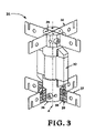
- FIG. 3 shows an example of a rotor with lower flexures configured with radial slots cut into them to create a plurality of ligaments to reduce the axial stiffness that the lower flexures provide to the rotor.
- FIG. 4 shows an example of a rotor with lower flexures configured with an elliptical cross-section to reduce the axial stiffness that the lower flexures provide to the rotor.
- FIG. 5 shows an example of a swing arm shown with a first sensor target and a second sensor target.
- FIG. 6 shows an example of a magnetic circuit for a normal-stress variable reluctance actuator referred to as the “pinched rotor” design.
- FIG. 7 illustrates a pair of graphs generated by an analysis of the magnetic forces and torques acting on the rotor in FIG. 6 , and illustrates the two-direction independence of torque and force.
- FIG. 8 shows an example of a magnetic circuit for a normal-stress variable reluctance actuator referred to as the “sandwiched rotor” design.
- FIG. 9 illustrates a pair of graphs generated by an analysis of the magnetic forces and torques acting on the rotor of FIG. 8 , and illustrates the one-direction dependence of force on torque.
- FIG. 10 shows an example of a magnetic circuit for a normal-stress variable reluctance actuator referred to as the “reversed roles sandwiched rotor” design.
- FIG. 11 illustrates a pair of graphs generated by an analysis of the magnetic forces and torques acting on the rotor in FIG. 10 , and illustrates the two-direction independence of torque and force.
- FIG. 12 provides a comparison of the pros and cons of the magnetic circuits shown in FIGS. 6 , 8 , and 10 .
- FIG. 13 shows an example of a variation of the magnetic circuit of FIG. 8 , with a permanent magnet used to provide the bias flux.
- FIG. 14 shows a modification of the magnetic circuit of FIG. 8 , with the back-iron air gaps removed to illustrate what happens when a high reluctance path is not included in the high magnetically-permeable back-iron.
- FIG. 15 shows the top view of a first reduced-flexure rotor assembly that can be employed as the rotor in the magnetic circuits shown in FIG. 6 , 8 , 10 , or 13 .
- FIG. 16 shows the top view of a second reduced-flexure rotor assembly that can be employed as the rotor in the magnetic circuits shown in FIG. 6 , 8 , 10 , or 13 .
- FIG. 17 shows the top view of a third reduced-flexure rotor assembly that can be employed as the rotor in the magnetic circuits shown in FIG. 6 , 8 , 10 , or 13 .
- FIG. 18 shows a simple, potentially low-cost, rotary actuator that uses a rubber sheet permanent magnet to produce a bias flux, separate the steering flux path from the bias flux paths, and to form a bearing between the rotor and the stator.
- FIG. 19 shows the system of FIG. 18 with the permanent magnet material moved out of the rubber sheet permanent magnet, resulting in a separate rubber sheet bearing and permanent magnet.
- FIG. 20 shows the system of FIG. 19 with the permanent magnet replaced by a combination of a permanent magnet and two low magnetic-permeability spacers.
- FIG. 21 shows the rotary actuator of FIG. 20 with the rotor removed to better illustrate the other components.
- FIG. 22 shows a possible arrangement of two displacement measuring sensors for measuring the displacement of the rotor relative to the stator.
- FIG. 23 shows the rotary actuator of FIG. 20 with the addition of the two displacement sensors.
- FIG. 24 shows the addition of a separate optical element to the front surface of the rotor.
- FIG. 25 shows the rotary actuator of FIG. 20 with the addition of a cutting tool.
- FIG. 26 shows the tool moved to a location near an edge of the rotor.
- FIG. 28 shows the tip of the tool coincident with the rotation axis of the rotor.
- FIG. 29 shows a simple, potentially low-cost, rotary actuator having two rotary degrees of freedom.
- FIG. 30 shows the second stator, its two outer stator poles, and its central stator pole.
- FIG. 31 shows the first stator positioned with the second stator.
- FIG. 32 shows a permanent magnet positioned against the first stator and the central stator pole of the second stator.
- FIG. 33 shows the common bias flux pole piece that is positioned against the permanent magnet. Two axes of rotation intersect at the center of a spherical seat in the common bias flux pole piece.
- FIG. 34 shows the addition of a spherical bearing.
- FIG. 35 shows the spherical bearing accepting the rotor central pole.
- FIG. 36 shows the addition of the steering flux coils to the two stators.
- FIG. 37 is a first cross-sectional view of the system shown in FIG. 29 .
- FIG. 38 is a second cross-sectional view of the system shown in FIG. 29 .
- FIG. 39 shows a possible arrangement of four displacement measuring sensors for measuring the displacement of the rotor relative to the stators.
- FIG. 40 shows the rotary actuator of FIG. 29 with the addition of the four displacement measuring sensors.
- FIG. 41 shows a cross-sectional view of the system of FIG. 40 to better illustrate two of the four displacement measuring sensors.
- FIG. 42 shows the addition of a separate optical element to the front surface of the rotor.
- FIG. 43 shows the rotary actuator of FIG. 40 with the addition of a cutting tool.
- FIG. 44 shows the tool moved to a location near an edge of the rotor.
- FIG. 45 shows the tip of the tool located in front of the intersections of the two rotation axes of the rotor.
- FIG. 46 shows the tip of the tool coincident with the intersections of the two rotation axes of the rotor.
- FIG. 1 shows a rotor, generally designated by the reference numeral 1 , as described in U.S. Patent Application Publication No. 2005/0166726 A1, entitled “Rotary Fast Tool Servo System and Methods,” to Montesanti et al., and which is herein incorporated by reference in its entirety.
- a rotor 1 includes, but is not limited to, a swing arm 2 , a counter weight 4 , a seal 6 , such as an o-ring, one or more rotor cores 10 , and of note for purposes of the discussion of FIG. 1 , upper flexures 8 and lower flexures 12 having a high in-plane stiffness compared to a low out-of-plane bending stiffness.
- Such a design creates a radial and axial constraint at both ends of rotor 1 , which is therefore over-constrained in the axial direction (as shown by the dashed line and denoted by the letter A).
- FIG. 2 shows a beneficial method for fixing the outer ends of the flexures (e.g., lower flexures 12 , as shown in FIG. 2 , with a clamping block (e.g., reference numeral 14 ) and upper flexures 8 with a clamping block.
- a clamping block e.g., reference numeral 14
- upper flexures 8 with a clamping block.
- Solutions (1) and (2) can be employed with the example embodiment shown in FIG. 2 and detailed in incorporated by reference U.S. Patent Application Publication No. 2005/0166726 A1.
- Solution (3) can be realized by the alternate example embodiments shown in FIG. 3 and FIG. 4 discussed below.
- the upper flexures 8 and lower flexures 12 as shown in FIG. 1 and FIG. 2 allows using the same mounting hardware for both (e.g. upper hub 35 and lower hub 36 , as shown in FIG. 3 , and outer clamping blocks 14 , as shown in FIG. 2 ).
- the stiffness of the radial and torsional constraints provided to the rotor 1 as shown in FIG.
- a lower flexure 37 can be configured with radial slots 38 cut into them to create a plurality of ligaments 39 to reduce the axial stiffness that the lower flexures provide to the rotor, now shown generally designated as reference numeral 31 , compared to the higher axial stiffness that the upper flexures 32 provide to rotor 31 .
- Rotor 31 is axially fixed by the upper flexures 32 and has a relaxed axial constraint from the lower flexures 37 .
- the size of the slots 38 and number of ligaments 39 can be varied to adjust the stiffness characteristics of the lower flexures 37 .
- the upper flexures 39 and lower flexures 37 both provide a radial constraint to the rotor, and together guide rotation of rotor 31 around an axis of rotation (denoted by the letter A).
- a differential axial length change of rotor 31 relative to the bottom portion 17 and top portion 18 of stator housing 16 is accommodated by the reduced stiffness of the lower flexures 37 , as shown in FIG. 3 , and the stresses in all of the flexures are lower than in the case with identical upper and lower flexures, e.g., flexures 8 and 12 as shown in FIG. 1 .
- the stiffness of the radial and torsional constraints provided to the rotor 31 of FIG. 3 by the lower flexures 37 is not the same as the stiffness of the radial and torsional constraints provided by the upper flexures 32 , which can lead to additional vibration modes of the rotor compared to the case of identical upper and lower flexures 8 and 12 as shown in FIG. 1 .
- Increasing the overall height of the lower flexure blades enables setting the total cross-sectional area of ligaments 39 to be equal to the cross-sectional area of upper flexures 32 .
- the stiffness of the radial and torsional constraints provided to the rotor is substantially the same for the upper and lower sets of flexures.
- a trade-off can be made between the benefits of a less over-constrained rotor and identical mounting hardware against the deleterious effects of possible additional vibration modes.
- FIG. 4 shows an example rotor arrangement, generally designated by reference numeral 41 , wherein configured lower flexures 48 have an elliptical cross-section to reduce the axial stiffness that the lower flexures provide to the rotor 41 compared to the higher axial stiffness that the upper flexures 42 provide to the rotor.
- Rotor 41 can be axially fixed by upper flexures 42 and has a relaxed axial constraint from the lower flexures 48 .
- Upper flexures 42 and lower flexures 48 both provide a radial constraint to rotor 41 , and together guide rotation of rotor 41 around an axis of rotation (again shown denoted by the letter A).
- a differential axial length change of rotor 41 relative to bottom portion 17 and top portion 18 of the stator housings 16 and 18 , as shown in FIG. 2 is accommodated by the reduced stiffness of lower flexures 48 , and the stresses in all of the flexures are lower than in the case with identical upper and lower flexures, e.g., flexures 8 and 12 as shown in FIG. 1 .
- the cross-section dimensions “a” and “b” of lower flexures 48 can be chosen so that the stiffness of the radial and/or torsional constraints provided to rotor 41 by lower flexures 48 is the same as the stiffness of the radial and torsional constraints provided by the upper flexures 42 .
- lower flexures 48 can be configured with rectangular cross-sections.
- the lower flexures 48 whether having an elliptical cross-section or a rectangular cross-section, require different mounting hardware for fixing them to the rotor (e.g., a lower hub 47 ) and to the stator (not shown) than the mounting hardware for fixing upper flexures 42 .
- the present invention can be arranged to match the stiffness of the radial and/or torsional constraints provided to the rotor 41 by upper flexures 42 and lower flexures 48 so as to avoid/reduce the additional vibration modes of the rotor that arise in the example embodiment depicted in FIG. 3 .
- a trade-off can be made between the benefits of a less over-constrained rotor against the deleterious effects of non-identical mounting hardware.
- a swing arm generally designated by reference numeral 50
- first sensor target 55 that is communicatively coupled to a first displacement sensor (not shown)
- second sensor target 56 that is communicatively coupled to a second displacement sensor (not shown).
- First sensor target 55 can be substantially displaced from an axis of rotation (again denoted by the letter A) and second sensor target 56 can be substantially aligned with axis of rotation A. From such an arrangement first sensor target 55 and its displacement sensor (not shown) provides information on the displacement of a tool 90 due to rotation and translation of swing arm 50 .
- Second sensor target 56 and its displacement sensor provides information on the displacement of the axis of rotation A.
- the information from the first sensor that is communicatively coupled to first sensor target 55 can be used by a control system (not shown) to control a rotation of the swing arm 50 .
- the information from the second sensor that is communicatively coupled to second sensor target 56 can be used by a control system to control a displacement of the axis of rotation A.
- the information from the first sensor that is communicatively coupled to first sensor target 55 and the information from the second sensor that is communicatively coupled to second sensor target 56 can be used by a control system of the present invention to separate the displacement of tool 90 caused by a rotation of the swing arm 50 from the displacement of tool 90 caused by a displacement of the axis of rotation A.
- viscous squeeze-film damping can be added to the rotor example embodiments 31 and 41 as respectively shown in FIGS. 3 and 4 , by constraining a layer of viscous fluid in the air gaps (not shown) between the rotor (e.g., a rotor laminate stack) 30 and 40 , as respectively shown in FIG. 3 and FIG. 4 , and the stator pole faces (not shown).
- viscous squeeze-film damping can also be added to swing arm 50 by constraining a layer of viscous fluid in the air gaps (not shown) between one or both of the sensor targets 55 and 56 , as shown in FIG. 5 , and their respective sensor (not shown).
- FIG. 6 shows a magnetic circuit for a normal-stress variable reluctance actuator referred to as the “pinched rotor” design because the magnetically permeable rotor 100 appears to be being pinched by the two magnetically permeable stator pieces 200 and 300 .
- the bias flux coil 90 produces a magnetic flux that circulates in a bias flux path.
- the triple-headed arrows represent the bias flux.
- bias flux path starts at bias flux coil 90 , goes through the magnetically permeable back-iron 61 to the back-iron air gap 82 , across air gap 82 , through both legs of the stator piece 300 to air gaps 64 and 66 , across air gaps 64 and 66 , through rotor 100 to air gaps 60 and 62 , across the air gaps 60 and 62 , through both legs of the stator piece 200 , across the back-iron air gap 80 , and through the back-iron 61 to bias coil 90 .
- the nominal length of the rotor-stator air gaps 60 , 62 , 64 , and 66 are equal, the nominal cross-sectional area of the air gaps 60 , 62 , 64 , and 66 are equal, and the lengths of the back-iron air gaps 80 and 82 are greater than the lengths of the rotor-stator air gaps 60 , 62 , 64 , and 66 .
- sections of rotor 100 and stator pieces 200 and 300 that are subjected to a time-varying magnetic flux are most often beneficially constructed from a laminated or powdered magnetic material with high permeability at the operating frequency of interest to reduce eddy current and magnetic hysteresis losses in the material.
- the first steering flux coil 70 is configured to produce a magnetic flux that circulates in a first steering flux path and the second steering flux coil 72 produces a nominally equal magnitude magnetic flux that circulates in a second steering flux path.
- the double-headed arrows, as shown in FIG. 6 represent the torque-producing flux in each stator piece.
- the first steering flux path starts at the steering coil 70 , goes through the stator piece 200 to air gap 62 , across air gap 62 , through rotor 100 to air gap 60 , across air gap 60 , and through the stator piece 200 to the steering coil 70 .
- back-iron air gap 80 provides a high reluctance path to separate the first steering flux path from the bias flux path.
- the second steering flux path starts at the steering coil 72 , goes through the stator piece 300 to the air gap 64 , across air gap 64 , through the rotor 100 to air gap 66 , across air gap 66 , and through stator piece 300 to the steering coil 72 .
- back-iron air gap 82 provides a high reluctance path to separate the second steering flux path from the bias flux path.
- back-iron air gaps 80 and 82 can be replaced by a spacer having a low magnetic permeability to provide a high reluctance path to also separate the first steering flux path and the second steering flux path from the bias flux path.
- the bias flux and steering fluxes are designed to add in air gaps 60 and 64 , and subtract in air gaps 62 and 66 , producing a net torque on rotor 100 from the magnetic forces acting on it, resulting in the counterclockwise rotation (shown denoted by ⁇ and an accompanying directional arrow) of the rotor shown in FIG. 6 . Reversing the directions of the two steering fluxes reverses the direction of the torque acting on rotor 100 and hence its angular rotation ⁇ .
- each of the steering flux coils 70 and 72 can be made up of one or more coils acting together or independently for producing a particular desired steering flux.
- the steering fluxes are controlled by a closed-loop feedback control system that uses a measurement of the angular rotation ⁇ for controlling rotation and for providing dynamic rotation stiffness to the rotor.
- the steering fluxes are controlled by a closed-loop feedback control system that uses a measurement of the rotation ⁇ for providing electronic damping to the rotational motion of the rotor.
- nominally unequal magnitude steering fluxes in the first and second steering flux paths can create a force on rotor 100 in FIG. 6 , resulting in a translation along a linear direction (as denoted by the letter Z and a directional arrow). This can be accomplished by increasing the current in one of steering coils 70 or 72 , or by decreasing the current in one of such steering coils, or by increasing the current in one of the steering coils and decreasing the current in the other steering coil.
- the single-head arrows represent the force-producing flux in each stator piece.
- the steering fluxes are controlled by a closed-loop feedback control system that uses a measurement of the translation Z for controlling that translation and providing dynamic translation stiffness to the rotor.
- the steering fluxes are controlled by a closed-loop feedback control system that uses a measurement of the translation Z for providing electronic damping to the translation motion of the rotor.
- FIG. 7 shows a pair of graphs generated by an analysis of the magnetic forces and torques acting on the rotor 100 in FIG. 6 , and illustrates the two-direction independence of torque and force.
- the magnetic circuit shown in FIG. 6 is a variation on the magnetic circuit for a normal-stress variable reluctance actuator that is taught in U.S. Patent Application Publication No. 2004/0035266 A1, entitled, “Rotary fast tool servo system and methods,” by Richard C. Montesanti and David L. Trumper, and of which, is herein incorporated by reference in its entirety.
- the present invention improves upon the device described in US 2004/0035266 A1 by providing a high reluctance path for separating the steering flux and the bias flux when a coil is used to provide the bias flux.
- magnetic flux preferentially follows a low reluctance path instead of a high reluctance path. It is also well known that the reluctance of a path depends on the magnetic permeability of the material that the path is made of, and that the permeability for a magnetic material depends on the frequency of oscillation of the magnetic field.
- the high reluctance paths created by the back-iron air gaps 80 and 82 as shown in FIG. 6 , substantially confine the steering flux to the steering flux paths, and the bias flux to the bias flux path, at the intended frequencies and ranges of motion for the actuator.
- Such high reluctance paths created by the back-iron air gaps 80 and 82 substantially separate the steering flux paths and the bias flux path, ensuring that the actuator generates a desired rotary motion for a particular set of currents in the steering flux coils, and ensures that the actuator generates a desired linear motion for a particular set of currents in the steering flux coils.
- the high reluctance paths created by the back-iron air gaps 80 and 82 magnetically decouples the two stator pieces 200 and 300 , making it easier to independently control the steering magnetic flux in each stator piece. Independent control of the steering magnetic flux in each stator piece allows the creation of a controllable force on the rotor.
- the actuator is intended to operate at 10,000 cycles per second or greater.
- the air gaps between the rotor and stator have a nominal length of about 50 micrometers, and the rotor makes contact with the stator during operation, closing at least one of the air gaps.
- FIG. 6 of the present invention allows easy adjustment of the bias flux; by changing the amount of electrical current flowing through the bias coil 90 .
- FIG. 8 shows a magnetic circuit for a normal-stress variable reluctance actuator referred to as the “sandwiched rotor” design because the magnetically permeable rotor 100 appears to be sandwiched between the two magnetically permeable stator pieces 200 and 300 .
- the bias flux coil 90 produces a magnetic flux that circulates in a bias flux path.
- the triple-headed arrows represent the bias flux.
- the bias flux path starts at the bias coil 90 , goes through the magnetically permeable back-iron 61 to the back-iron air gap 82 , across air gap 82 , through both legs of the stator piece 300 to air gaps 64 and 66 , across air gaps 64 and 66 , through rotor 100 to air gaps 60 and 62 , across the air gaps 60 and 62 , through both legs of the stator piece 200 , across the back-iron air gap 80 , and through the back-iron 61 to the bias coil 90 .
- the nominal length of the rotor-stator air gaps 60 , 62 , 64 , and 66 are equal, the nominal cross-sectional area of the air gaps 60 , 62 , 64 , and 66 are equal, and the lengths of the back-iron air gaps 80 and 82 are greater than the lengths of the rotor-stator air gaps 60 , 62 , 64 , and 66 .
- sections of rotor 100 and stator pieces 200 and 300 that are subjected to a time-varying magnetic flux are most often beneficially constructed from a laminated or powdered magnetic material with high permeability at the operating frequency of interest to reduce eddy current and magnetic hysteresis losses in the material.
- the first steering flux coil 70 produces a magnetic flux that circulates in a first steering flux path and the second steering flux coil 72 produces a nominally equal magnitude magnetic flux that circulates in a second steering flux path.
- the double-headed arrows represent the torque-producing flux in each stator piece.
- the first steering flux path starts at the steering coil 70 , goes through the stator piece 200 to the air gap 62 , across air gap 62 , through the rotor 100 to air gap 60 , across air gap 60 , and through the stator piece 200 to the steering coil 70 .
- the back-iron air gap 80 provides a high reluctance path to separate the first steering flux path from the bias flux path.
- the second steering flux path starts at the steering coil 72 , goes through the stator piece 300 to the air gap 64 , across air gap 64 , through the rotor 100 to air gap 66 , across air gap 66 , and through the stator piece 300 to the steering coil 72 .
- the back-iron air gap 82 provides a high reluctance path to separate the second steering flux path from the bias flux path.
- back-iron air gaps 80 and 82 can be replaced by a spacer having a low magnetic permeability to provide a high reluctance path to separate the first steering flux path from the bias flux path.
- the bias flux and steering fluxes are designed to add in air gaps 60 and 64 , and subtract in air gaps 62 and 66 , producing a net torque on the rotor 100 from the magnetic forces acting on it, resulting in the counterclockwise rotation ⁇ of the rotor shown in FIG. 8 . Accordingly, by reversing the directions of the two steering fluxes reverses the direction of the torque acting on the rotor 100 and hence its rotation ⁇ .
- each of the steering flux coils 70 and 72 can be made up of more than one coil acting together or independently for producing a particular desired steering flux.
- the steering fluxes can be controlled by a closed-loop feedback control system that uses a measurement of the rotation ⁇ for controlling the rotation and for providing dynamic rotation stiffness to the rotor.
- the steering fluxes can be controlled by a closed-loop feedback control system that uses a measurement of the rotation ⁇ for providing electronic damping to the rotational motion of the rotor.
- nominally unequal magnitude steering fluxes in the first and second steering flux paths can create a force on the rotor 100 in FIG. 8 , resulting in the translation Z. This can be accomplished by increasing the current in one of the steering coils 70 or 72 , or by decreasing the current in one of the steering coils, or by increasing the current in one of the steering coils and decreasing the current in the other steering coil.
- the single-head arrows represent the force-producing flux in each stator piece.
- the steering fluxes can be controlled by a closed-loop feedback control system that uses a measurement of the translation Z for control for controlling that translation and providing dynamic translation stiffness to the rotor.
- the steering fluxes can be controlled by a closed-loop feedback control system that uses a measurement of the translation Z for providing electronic damping to the translation motion of the rotor.
- the torque and force produced on the rotor are not independent of each other: changing the force nominally does not affect the torque, but changing the torque does affect the force.
- FIG. 9 shows a pair of graphs generated by an analysis of the magnetic forces and torques acting on the rotor 100 of FIG. 8 , and illustrates the one-direction dependence of force on torque.
- a force can be produced by the magnetic circuit in FIG. 8 as long as a torque is being produced by it.
- an external torque (not shown) needs to be maintained on the rotor 100 so that a torque producing flux can be present to act as an operating point for creating a force.
- FIG. 8 of the present invention shows an arrangement that is similar to a circuit disclosed in incorporated by reference
- FIG. 10 shows a magnetic circuit for a normal-stress variable reluctance actuator referred to as the “reversed roles sandwiched rotor” design because the magnetically permeable rotor 100 appears to be sandwiched between the two magnetically permeable stator pieces 200 and 300 and the roles of the coils and the nature of the flux paths for producing a torque on the rotor of FIG. 10 are reversed from the roles of the coils and flux paths as shown and as discussed above for the configuration of FIG. 8 .
- the first bias flux coil 70 produces a magnetic flux that circulates in a first bias flux path
- the second bias flux coil 72 produces a nominally equal magnitude bias flux that circulates in a second bias flux path.
- the triple-headed arrows represent the bias flux.
- the first bias flux path starts at bias coil 70 , goes through the stator piece 200 to the air gap 62 , across air gap 62 , through the rotor 100 to air gap 60 , across air gap 60 , and through the stator piece 200 to bias coil 70 .
- the back-iron air gap 80 provides a high reluctance path to separate the first bias flux path from the torque flux path in the back-iron 61 .
- the second bias flux path starts at bias coil 72 , goes through the stator piece 300 to the air gap 64 , across air gap 64 , through the rotor 100 to air gap 66 , across air gap 66 , and through the stator piece 300 to the steering coil 72 .
- the back-iron air gap 82 provides a high reluctance path to separate the second bias flux path from the torque flux path in the back-iron 61 .
- the back-iron air gaps 80 and 82 can be replaced by a spacer having a low magnetic permeability to provide a high reluctance path to separate the first steering flux path from the bias flux path.
- the torque flux coil 90 in FIG. 10 produces a magnetic flux that circulates in a torque flux path.
- the double-headed arrows represent the torque-producing flux.
- the torque flux path starts at the torque coil 90 , goes through the magnetically permeable back-iron 61 to the back-iron air gap 82 , across air gap 82 , through both legs of the stator piece 300 to air gaps 64 and 66 , across air gaps 64 and 66 , through the rotor 100 to air gaps 60 and 62 , across the air gaps 60 and 62 , through both legs of the stator piece 200 , across the back-iron air gap 80 , and through the back-iron 61 to the torque coil 90 .
- the nominal length of the rotor-stator air gaps 60 , 62 , 64 , and 66 are equal, the nominal cross-sectional area of the air gaps 60 , 62 , 64 , and 66 are equal, and the lengths of the back-iron air gaps 80 and 82 are greater than the lengths of the rotor-stator air gaps 60 , 62 , 64 , and 66 .
- sections of rotor 100 and stator pieces 200 and 300 that are subjected to a time-varying magnetic flux are most often beneficially constructed from a laminated or powdered magnetic material with high permeability at the operating frequency of interest to reduce eddy current and magnetic hysteresis losses in the material.
- the bias flux and torque fluxes are designed to add in air gaps 60 and 64 , and subtract in air gaps 62 and 66 , producing a net torque on the rotor 100 from the magnetic forces acting on it, resulting in the counterclockwise rotation ⁇ of the rotor shown in FIG. 10 . Reversing the direction of the torque flux reverses the direction of the torque acting on the rotor 100 and hence its rotation ⁇ .
- each of the bias flux coils 70 and 72 can be made up of more than one coil acting together or independently for producing a particular desired bias flux.
- the torque flux produced by torque coil 90 is controlled by a closed-loop feedback control system that uses a measurement of the rotation ⁇ for controlling the rotation and providing dynamic rotation stiffness to the rotor.
- the torque flux is controlled by a closed-loop feedback control system that uses a measurement of the rotation ⁇ for providing electronic damping to the rotational motion of the rotor.
- nominally unequal magnitude bias fluxes in the first and second bias flux paths can create a force on the rotor 100 , resulting in a translation Z.
- Such a method can be accomplished by increasing the current in one of the bias flux coils 70 or 72 , or by decreasing the current in one of the bias flux coils, or by increasing the current in one of the bias flux coils and decreasing the current in the other bias flux coil.
- the single-head arrows represent the force-producing flux in each stator piece.
- the bias fluxes are controlled by a closed-loop feedback control system that uses a measurement of translation Z for controlling the translation and for providing dynamic translation stiffness to the rotor.
- the bias fluxes are controlled by a control system that uses a measurement of translation Z for closed-loop feedback control for providing electronic damping to the translation motion of the rotor.
- FIG. 11 shows a pair of graphs generated by an analysis of the magnetic forces and torques acting on the rotor 100 in FIG. 10 , and illustrates the two-direction independence of torque and force.
- FIG. 12 provides a comparison of the pros and cons of the magnetic circuits shown in FIGS. 6 , 8 , and 10 ; suggesting reasons for preferring one over the other for a particular application.
- FIG. 13 shows a variation of the magnetic circuit of FIG. 8 , with a permanent magnet 81 used to provide the bias flux and create a high reluctance path in the back-iron 61 and 62 (all other reference numerals are the same as shown in FIG. 8 ). It is to be noted that one of ordinary skill in the art understands that certain high strength permanent magnets have a low magnetic permeability approaching that of free space, and therefore the permanent magnet 81 replaces the function of the air gaps 80 and 82 , as shown in FIG. 8 , which are not present in FIG. 12 .
- FIG. 14 shows another modification of the magnetic circuit of FIG. 8 , with the back-iron air gaps 80 and 82 removed to illustrate what happens when a high reluctance path is not included in the high magnetically-permeable back-iron 61 .
- an alternating magnetic flux can be produced primarily in two paths.
- the first path comprises the first stator piece 200 , the air gap 62 , the rotor 100 , and the air gap 60 back to the stator piece 200 .
- the second path comprises the first stator piece 200 , the back-iron 61 , the two legs of the second stator piece 300 , across air gaps 64 and 66 , through rotor 100 , and across air gap 60 back to the first stator piece 200 .
- stator pieces 200 and 300 and the back-iron 61 are made of a high magnetically-permeable material, then current 70 A can produce a significant magnetic flux in the first and second paths, which can couple with coils 70 B, 70 C, and 70 D and induce an alternating current in them.
- FIG. 8 A comparison of FIG. 8 , FIG. 10 , and FIG. 14 illustrates how the high reluctance paths provided by the back-iron air gaps 80 and 82 , e.g., as shown in FIG. 8 , decrease the coupling between alternating electrical currents flowing through coils 70 and 72 .
- an alternating current when an alternating current is applied to coil 70 , an alternating magnetic flux can be produced primarily in a path comprising the first stator piece 200 , the air gap 62 , the rotor 100 , and the air gap 60 back to the stator piece 200 .
- a second flux path exists in this case, comprising the first stator piece 200 , across the air gaps 62 and 64 via the rotor 100 , through the second stator piece 300 , across the air gaps 66 and 60 via the rotor 100 , and back to the first stator piece 200 .
- the flux induced by current introduced into coil 70 in the second path can be substantially less than the flux induced by current introduced in the first path because of the higher reluctance of the second path due to a nominal doubling of the air gaps in the second path, and therefore the alternating current induced in coil 72 is less than the current applied to coil 70 .
- a third flux path exists in this case, comprising the first stator piece 200 , across the back-iron air gap 80 , through the back-iron 61 , across the back-iron air gap 82 , through the two legs of the second stator piece 300 , across the air gaps 64 and 66 , through the rotor 100 , and across air gap 60 back to the first stator piece 200 .
- the flux induced by current in the third path induces an alternating current in coil 72 when the induced flux in the two legs of stator piece 300 is not balanced, as would be the case when the lengths of rotor-stator air gaps 64 and 66 are not equal, or when coil 72 includes two separate coils with one on each leg of stator piece 300 .
- the flux induced by current in the third path can be made significantly less than the flux in the first path by setting the lengths of the back-iron air gaps 80 and 82 to be significantly longer than the lengths of the rotor-stator air gaps 60 , 62 , 64 , and 66 . Therefore, the back-iron air gaps 80 and 82 create a high reluctance path in the back-iron 61 that magnetically decouples the stator pieces 200 and 300 when a coil is used to provide the bias flux.
- the difficulty of independently controlling the currents in coils 70 and 72 decreases when the magnetic coupling between the stator pieces 200 and 300 decreases.
- FIG. 15 shows the top view of a rotor assembly 5 that can be employed as the rotor 100 in the magnetic circuits shown in FIG. 6 , 8 , 10 , or 13 .
- rotor assembly 5 in FIG. 15 includes of a rotor core 10 coupled to at least an upper flexure hub 100 that in turn is connected to at least two flexure blades 110 and 120 that are fixed at their outer ends to a base 150 .
- a base 150 One of ordinary skill in the art recognizes that as drawn, the two flexure blades in FIG.
- rotor assembly 5 is employed as the rotor discussed above in any of the magnetic circuits shown in FIGS.
- the helper spring elements 130 and 140 are fixed at their outer ends to a base 150 and are connected to the at least upper flexure hub 100 .
- Spring elements 130 and 140 can be used to augment the dynamic stiffness provided to rotor core 10 in the translation direction 220 .
- the spring elements 130 and 140 are not present and all of the stiffness in the translational direction 220 is provided by an actuator operating in accordance with FIG. 6 , 8 , 10 , or 13 .
- the spring elements 130 and 140 are replaced with flexure blades identical to 110 and 120 , and the rotor assembly becomes the same as rotor assembly 31 and 41 , as respectively shown in FIGS. 3 and 4 .
- FIG. 16 shows a first variation of the rotor assembly 5 shown in FIG. 15 .
- the flexure blades 110 and 120 are oriented to substantially constrain the three translation degrees of freedom of a rotor core 10 .
- rotor core 10 is substantially free to rotate in the direction 210 about a centerline 200 , and that centerline 200 can wander in the translation directions 220 and 222 when the rotor is rotated in the direction 210 .
- the rotor assembly 5 is employed as the rotor 100 in any of the magnetic circuits shown in FIG.
- FIG. 17 shows a second variation of the rotor assembly 5 shown in FIG. 15 .
- flexure blades 110 and 120 are oriented to substantially constrain the three translation degrees of freedom of rotor core 10 .
- rotor core 10 is substantially free to rotate in the direction 210 about the centerline 200 , and that centerline 200 can wander in the translation directions 220 and 222 when the rotor is rotated in the direction 210 .
- rotor assembly 9 is employed as the rotor in any of the magnetic circuits shown in FIG.
- FIGS. 15 , 16 , and 17 represent three possible arrangements of at least two flexure blades 110 and 120 and optional at least two helper springs 130 and 140 for providing a bearing for a rotor core 10 .
- Those of ordinary skill in the art recognize that a continuum exists for the possible angles between the flexure blades 110 and 120 and for the possible angles between the flexure blades and rotor core 10 .
- FIG. 18 shows a simple, potentially low-cost, rotary actuator that uses a rubber sheet permanent magnet 700 to produce a bias flux, to separate the steering flux path 685 from the bias flux paths 701 and 702 , and to form a bearing between the rotor 500 and the stator 600 .
- the arrow shown on the rubber sheet permanent magnet 700 indicates the north-pole direction. Note the large potential work zone at the front face of the rotor 500 . If the actuator is used in a fast tool servo, then the cutting tool can be arranged to engage a large workpiece. Alternatively, if the actuator is used to rotate an optical element, that optical element can be made integral with the exposed front face of the rotor or mounted directly to it.
- Potential optical elements include a reflective element, e.g., a mirror configured with a flat, concave, convex, or complex surface, a refractive element, or a diffractive element.
- a rubber sheet permanent magnet is a sheet of elastic material that has permanent magnet properties.
- a rubber sheet magnet can be up to and/or greater than about a 0.5 mm thick layer of rubber impregnated with particles of ceramic permanent magnet that are oriented in a common direction.
- rubber sheet permanent magnet 700 , stator central pole 630 , and rotor central pole 540 have mating curved surfaces that have a common center on the axis of rotation 550 of rotor 500 .
- rubber sheet permanent magnet 700 can be made up of multiple layers of rubber sheet permanent magnets and high magnetic permeability material, and the particular composition and thickness of the layers is chosen to achieve desired mechanical and magnetic properties of rubber sheet permanent magnet 700 .
- One of ordinary skill in the art can recognize that if the axis of rotation 550 is chosen so that it passes through the combined center of mass of the moving elements 500 and 540 , then the moving elements may not develop a linear acceleration and attendant reaction force.
- rubber sheet permanent magnets provide a source of magnetic flux that flows through two elements, to separate a steering flux path from a bias flux path, and to form a bearing between those two elements.
- a significant aspect of a rubber sheet bearing as utilized herein is that it can tolerate the compressive stress that results from the attraction of a rotor and stator in certain magnetic circuit topologies. This allows considering magnetic topologies such as the one shown in FIG. 18 , which can be difficult to realize if flexure blades were used (as shown in FIGS. 3 and 4 ) because of their intolerance to compressive stresses.
- the bias flux paths 701 and 702 start at the rubber sheet permanent magnet 700 , enter the magnetically permeable stator 600 at the stator central pole 630 , split and circulate through the stator to the left stator pole 610 and right stator pole 620 , cross the air gaps 510 and 520 to enter the magnetically permeable rotor 500 , travel through the rotor to the rotor central pole 540 , and return to the rubber sheet permanent magnet 700 .
- the lengths of the air gaps 510 and 520 are equal, and the cross-sectional area of the air gaps 510 and 520 are equal.
- sections of the rotor 500 and stator 600 that are subjected to a time-varying magnetic flux are most often beneficially constructed from a laminated or powdered magnetic material with high permeability at the operating frequency of interest to reduce eddy current and magnetic hysteresis losses in the material.
- the first steering flux coil 680 and the second steering flux coil 690 are arranged to produce magnetic flux that circulates in a common steering flux path 685 .
- the steering flux path starts at the first steering coil 680 in the left stator pole 610 , goes through the stator 600 to the right stator pole 620 , through the second steering flux coil 690 to the air gap 520 , across the air gap 520 to the rotor 500 , through the rotor 500 to the air gap 510 , across the air gap 510 to the left stator pole 610 , and returns to the first steering coil 680 .
- the rubber sheet permanent magnet 700 extends across substantially the entire width of the stator central pole 630 and the rotor central pole 540 , and is significantly thicker than the nominal length of the left rotor-stator air gap 510 and right rotor-stator air gap 520 . Therefore, the rubber sheet permanent magnet provides a high reluctance path that substantially prevents the steering flux from flowing across the space between the central poles of the stator and rotor, separating the steering flux path 685 from the bias flux paths 701 and 702 .
- the bias flux and steering fluxes are configured to add in air gap 520 and subtract in air gap 510 , producing a net torque on the rotor 500 from the magnetic forces acting on it, resulting in the counterclockwise rotation 530 of the rotor around the axis of rotation 550 shown in FIG. 131 .
- the flux addition and subtraction in the outer air gaps 510 and 520 does not appreciably change the magnitude of the net magnetic force acting on the rotor, but it does cause a lateral shift of that force.
- each of the steering flux coils 680 and 690 can be made up of more than one coil acting together or independently for producing a particular desired steering flux.
- the steering flux is controlled by a control system that uses a measurement of the rotation 530 for closed-loop feedback control for controlling that rotation and providing dynamic rotation stiffness to the rotor.
- the steering flux is controlled by a control system that uses a measurement of the rotation 530 for closed-loop feedback control for providing electronic damping to the rotational motion of the rotor.
- Typical rubber sheet permanent magnets have a low remanent flux of approximately 0.1 Tesla, which drives up the required cross-sectional area of the central stator pole 630 and the central rotor pole 540 .
- a total flux of 1.5 Tesla is desired in the outer rotor-stator air gaps 510 and 520 , with 0.75 Tesla provided by a typical rubber sheet permanent magnet having a permanent flux of 0.1 Tesla and 0.75 Tesla provided by the steering flux coils, then the cross-sectional area of the central poles 630 and 540 needs to be 7.5 times larger than the combined cross-sectional area of the outer rotor-stator air gaps 510 and 520 .
- the permanent magnet material has been moved out of the rubber sheet permanent magnet 700 , as shown in FIG. 18 , resulting in the rubber sheet bearing 505 and the permanent magnet 750 .
- the arrow shown on the permanent magnet 750 indicates the north-pole direction. Note that as with the rubber sheet permanent magnet, the permanent magnet 750 extends across substantially the entire width of the stator central pole 631 and the rotor central pole 540 , and is significantly thicker than the nominal length of the left rotor-stator air gap 510 and right rotor-stator air gap 520 .
- the permanent magnet 750 provides a high reluctance path that substantially prevents the steering flux from flowing across the space between the central poles of the stator and rotor, separating the steering flux path 685 from the bias flux paths 701 and 702 .
- the mechanical and magnetic properties of the bearing 505 and the bias flux source 750 can be more readily tailored to meet the performance goals for the actuator.
- the rubber bearing 505 can include of a single layer of elastomeric material, or it can be a composite consisting of separate layers of elastomeric material and metal. To better allow optimizing the dimensions of the permanent magnet 750 , it may be desirable to use a combination of the permanent magnet 755 and two low magnetic-permeability spacers 756 and 757 , as shown in FIG. 20 .
- FIG. 21 shows the rotary actuator of FIG. 20 with the rotor 500 removed to better illustrate the other components.
- the addition of a viscous fluid between the stator poles 610 and 620 and the rotor 500 can be used to provide mechanical damping to the rotor.
- FIG. 22 shows a possible arrangement of two displacement measuring sensors 902 and 904 for measuring the displacement of the rotor 500 relative to the stator 600 .
- the two sensors measure rotation of the rotor 500 around the axis 550 , and translation of the rotor 500 towards/away from the stator 600 .
- candidate displacement sensors include eddy current sensors, capacitance sensors, and laser sensors. Those practiced in the art readily recognizes that the list of candidate sensors is not exhaustive, and that the effects of the time-varying magnetic flux carried by the stator poles 610 and 620 on the performance of the sensors needs to be considered when choosing a particular type of sensor.
- FIG. 23 shows the rotary actuator of FIG. 20 with the addition of the two displacement sensors 902 and 904 .
- FIG. 24 shows the addition of a separate optical element 910 to the front surface of the rotor 500 .
- Potential optical elements include a reflective element, e.g., a flat, concave, convex, or complex surface, a refractive element, or a diffractive element.
- the optical element can be fixedly attached or removeably attached.
- the optical element can be manufactured directly (e.g., via polishing said front face using methods known to one of ordinary skill in the art) onto the front face of the rotor 500 .
- FIG. 25 shows the rotary actuator of FIG. 20 with the addition of a cutting tool 920 .
- Rotation of the rotor 500 about the rotation axis 550 causes motion of the tool 920 away/towards the stator 600 .
- a torsionally flexible element 800 is attached to a base 900 and the rotor 500 .
- the base 900 is fixed relative to the stator 600
- the torsionally flexible element 800 is substantially aligned with the axis of rotation 550 of the rotor 500 and constrains translation of the rotor in a direction parallel to the axis 550 .
- the torsionally flexible element 800 and the bearing 505 form a bearing system that constrains the rotor 500 relative to the stator 600 in all degrees of freedom of motion except for rotation around the axis 550 .
- FIG. 26 the tool 920 has been moved to a location near an edge of the rotor 500 . This may be beneficial in some cases when compared to the tool location in FIG. 25 .
- the bearing 505 in FIGS. 23 , 24 , and 25 can also be a gas-film or fluid film bearing.
- the magnetic attractive forces between the stator central pole 631 and the rotor central pole 540 , as shown and detailed in FIG. 19 , due to the bias flux can provide a preload force on the bearing, and that a torsionally flexible element 800 and its base 900 , as shown in FIG. 25 , can provide an axial support to the rotor 500 .
- FIG. 27 shows the system of FIG. 25 with the tip of the tool 920 located in front of the rotation axis 550 of the rotor, and in a plane passing through the rotation axis. This configuration can be desired for an application where an oscillatory back and forth motion of the tool tip is desired.
- FIG. 28 the tip of the tool 920 is coincident with the rotation axis 550 of the rotor 500 .
- This configuration can be desirable for an application where rotation of the tool around its tip is desired.
- FIG. 28 depicts a system where the combined center of mass of the major rotating elements, 500 and 540 is not coincident with the axis of rotation 550 . If the resultant forces from the linear acceleration of the center of mass is intolerable in a certain application, then balance masses (not shown) can be added to the front face of the rotor.
- FIG. 29 shows a simple, potentially low-cost, rotary actuator having two rotary degrees of freedom.
- the rotor 1500 has a first rotation axis 1550 and a second rotation axis 2550 .
- the first stator 1600 and second stator 2660 act on the rotor to produce rotations 1530 and 2530 around rotation axes 1550 and 2550 , respectively.
- the actuator is used in a fast tool servo, then the cutting tool can be arranged to engage a large workpiece.
- the actuator is used to rotate an optical element, that optical element can be made integral with the exposed front face of the rotor or mounted directly to it.
- Potential optical elements include a reflective element having, (e.g., a mirror having a flat, concave, convex, or complex surface), a refractive element, or a diffractive element.
- FIG. 30 shows the second stator 2600 , its two outer stator poles 2610 and 2620 , and its central stator pole 2615 .
- FIG. 31 shows the first stator 1600 positioned with the second stator 2600 .
- the first stator 1600 has two outer stator poles 1610 and 1620 , and an opening to provide a space 1615 between the first stator 1600 and the central stator pole 2615 of the second stator 2600 .
- FIG. 32 shows a permanent magnet 1750 positioned against the first stator 1600 and the central stator pole 2615 of the second stator 2600 .
- the arrow shown on the permanent magnet 1750 indicates the north-pole direction.
- FIG. 33 shows the common bias flux pole piece 1630 that is positioned against the permanent magnet 1750 .
- the two axes 1550 and 2550 intersect at the center of the spherical seat 1635 in the common bias flux pole piece 1630 .
- FIG. 34 shows the addition of a spherical bearing 1505 to the spherical seat 1635 .
- the bearing 1505 can be an elastomeric layer, a lamination of elastomeric and metal layers, or a gas-film or fluid film bearing.
- the magnetic attractive forces between the common bias flux pole piece 1630 and the rotor central pole 1540 due to the bias flux can provide a preload force on the bearing.
- FIG. 35 shows the spherical bearing 1505 accepting the rotor central pole 1540 and FIG. 36 shows the addition of the steering flux coils 1680 and 1690 for the first stator 1600 , and the addition of one 2680 of the pair of steering flux coils (the other coil 2690 is hidden in FIG. 36 ) for the second stator 2600 .
- FIG. 37 is a first cross-sectional view of the system shown in FIG. 39 , illustrating the magnetic flux paths through the first stator 1600 and the rotor 1500 .
- the bias flux paths 1701 and 1702 start at the permanent magnet 1750 , enter the magnetically permeable first stator 1600 , split and circulate through the first stator to the left first stator pole 1610 and right first stator pole 1620 , cross the air gaps 1510 and 1520 to enter the magnetically permeable rotor 1500 , travel through the rotor to the rotor central pole 1540 , pass across the bearing 1505 , through the magnetically permeable common bias flux pole piece 1630 , and return to the permanent magnet 1750 .
- the lengths of the air gaps 1510 and 1520 are equal, and the cross-sectional area of the air gaps 1510 and 1520 are equal.
- the sections of the rotor 1500 and first stator 1600 that are subjected to a time-varying magnetic flux are most often constructed from a laminated or powdered magnetic material with high permeability at the operating frequency of interest to reduce eddy current and magnetic hysteresis losses in the material.
- the first steering flux coil 1680 and the second steering flux coil 1690 produce magnetic flux that circulates in a common steering flux path 1685 .
- the steering flux path starts at the first steering coil 1680 in the left first stator pole 1610 , goes through the first stator 1600 , around the second stator central pole 2615 to the right first stator pole 1620 , through the second steering flux coil 1690 to the air gap 1520 , across the air gap 1520 to the rotor 1500 , through the rotor 1500 to the air gap 1510 , across the air gap 1510 to the left first stator pole 1610 , and returns to the first steering coil 1680 .
- the permanent magnet 1750 provides a high reluctance path that substantially separates the steering flux path 1685 from the bias flux paths 1701 and 1702 .
- the space 1615 substantially prevents the steering flux 1685 from entering the second stator 2600 .
- the space 1615 can be filled with a low magnetically-permeable material that can add mechanical integrity to the assembly.
- the bias flux and steering fluxes add in air gap 1520 and subtract in air gap 1510 , producing a net torque on the rotor 1500 from the magnetic forces acting on it, resulting in the rotation 1530 of the rotor around the axis of rotation 1550 .
- the flux addition and subtraction in the outer air gaps 1510 and 1520 does not appreciably change the magnitude of the net magnetic force acting on the rotor, but it does cause a lateral shift of that force.
- the steering flux 1685 reverses the direction of the torque acting on the rotor 1500 and hence its rotation 1530
- each of the steering flux coils 1680 and 1690 can be made up of more than one coil acting together or independently for producing a particular desired steering flux.
- the steering flux is controlled by a control system that uses a measurement of the rotation 1530 for closed-loop feedback control for controlling that rotation and providing dynamic rotation stiffness to the rotor.
- the steering flux is controlled by a control system that uses a measurement of the rotation 1530 for closed-loop feedback control for providing electronic damping to the rotational motion of the rotor.
- FIG. 38 is a second cross-sectional view of the system shown in FIG. 29 , illustrating the magnetic flux paths through the second stator 2600 and the rotor 1500 .
- the bias flux paths 2701 and 2702 start at the permanent magnet 1750 , enter the magnetically permeable central pole 2615 of the second stator 2600 , split and circulate through the second stator to the left second stator pole 2610 and right second stator pole 2620 , cross the air gaps 2510 and 2520 to enter the magnetically permeable rotor 1500 , travel through the rotor to the rotor central pole 1540 , pass across the bearing 1505 , through the magnetically permeable common bias flux pole piece 1630 , and return to the permanent magnet 1750 .
- lengths of the air gaps 2510 and 2520 are equal, and the cross-sectional area of the air gaps 2510 and 2520 are equal.
- sections of the rotor 1500 and second stator 2600 that are subjected to a time-varying magnetic flux are most often constructed from a laminated or powdered magnetic material with high permeability at the operating frequency of interest to reduce eddy current and magnetic hysteresis losses in the material.
- the first steering flux coil 2680 and the second steering flux coil 2690 produce magnetic flux that circulates in a common steering flux path 2685 .
- the steering flux path starts at the first steering coil 2680 in the left second stator pole 2610 , goes through the second stator 2600 , to the right second stator pole 2620 , through the second steering flux coil 2690 to the air gap 2520 , across the air gap 2520 to the rotor 1500 , through the rotor 1500 to the air gap 2510 , across the air gap 2510 to the left second stator pole 2610 , and returns to the first steering coil 2680 .
- the permanent magnet 1750 provides a high reluctance path that substantially separates the steering flux path 2685 from the bias flux paths 2701 and 2702 .
- the space 1615 substantially prevents the steering flux 2685 from entering the first stator 1600 .
- the space 1615 can be filled with a low magnetically-permeable material that can add mechanical integrity to the assembly.
- the bias flux and steering fluxes add in air gap 2520 and subtract in air gap 2510 , producing a net torque on the rotor 1500 from the magnetic forces acting on it, resulting in the rotation 2530 of the rotor around the axis of rotation 2550 .
- each of the steering flux coils 2680 and 2690 can be made up of more than one coil acting together or independently for producing a particular desired steering flux.
- the steering flux is controlled by a closed-loop feedback control system that uses a measurement of the rotation 2530 for controlling that rotation and providing dynamic rotation stiffness to the rotor.
- the steering flux is controlled by a closed-loop feedback control system that uses a measurement of the rotation 2530 for providing electronic damping to the rotational motion of the rotor.
- FIG. 39 shows a possible arrangement of four displacement measuring sensors 1902 , 1904 , 2902 , and 2904 for measuring the displacement of the rotor 1500 relative to the stators 1600 and 2600 .
- the two sensors 1902 and 1904 measure rotation of the rotor 1500 around the axis 1550 , and translation of the rotor 1500 towards/away from the stator 1600 .
- the two sensors 2902 and 2904 measure rotation of the rotor 1500 around the axis 2550 , and translation of the rotor 1500 towards/away from the stator 2600 .
- Candidate displacement sensors include eddy current sensors, capacitance sensors, and laser sensors.
- the list of candidate sensors is not exhaustive, and that the effects of the time-varying magnetic flux carried by the stator poles 1610 , 1620 , 2610 , and 2620 on the performance of the sensors needs to be considered when choosing a particular type of sensor.
- FIG. 40 shows the rotary actuator of FIG. 29 with the addition of the four displacement measuring sensors 1902 , 1904 , 2902 , and 2904 .
- FIG. 41 shows a cross-sectional view of the system of FIG. 40 to better illustrate two of the four displacement measuring sensors.
- FIG. 42 shows the addition of a separate optical element 910 to the front surface of the rotor 1500 .
- Potential optical elements include a mirror (flat, concave, convex, or complex surface), a refractive element, or a diffractive element.
- the optical element can be fixedly attached or removeably attached. Alternately, the optical element can be manufactured directly onto the front face of the rotor 1500 .
- FIG. 43 shows the rotary actuator of FIG. 40 with the addition of a cutting tool 1920 .
- Rotation of the rotor 1500 about the rotation axis 1550 causes motion of the tool 1920 predominantly away/towards the stator 1600 .
- Rotation of the rotor 1500 about the rotation axis 2550 causes motion of the tool 1920 predominantly up/down relative to the stator 2600 .
- This combined tool motion may preferable in certain machining applications.
- the tool 1920 has been moved to a location near an edge of the rotor 1500 . This may be beneficial in some cases when compared to the tool location in FIG. 43 .
- FIG. 45 shows the system of FIG. 43 with the tip of the tool 1920 located in front of the intersections of the rotation axes 1550 and 2550 of the rotor. This configuration can be desirable for an application where an oscillatory back and forth motion and/or up and down is desired.
- FIG. 46 the tip of the tool 1920 is coincident with the intersections of the rotation axes 1550 and 2550 of the rotor 1500 .
- This configuration can be desirable for an application where rotation of the tool around its tip is desired.
- FIG. 46 depicts a system where the combined center of mass of the major rotating elements, 1500 and 1540 is not coincident with the axes of rotation 1550 and 2550 . If the resultant forces from the linear acceleration of the center of mass are intolerable in a certain application, then balance masses (not shown) can be added to the front face of the rotor.
Abstract
Description
Claims (58)
Priority Applications (1)
| Application Number | Priority Date | Filing Date | Title |
|---|---|---|---|
| US11/490,988 US7492117B2 (en) | 2005-07-20 | 2006-07-20 | Electromagnetic variable degrees of freedom actuator systems and methods |
Applications Claiming Priority (2)
| Application Number | Priority Date | Filing Date | Title |
|---|---|---|---|
| US70117605P | 2005-07-20 | 2005-07-20 | |
| US11/490,988 US7492117B2 (en) | 2005-07-20 | 2006-07-20 | Electromagnetic variable degrees of freedom actuator systems and methods |
Publications (2)
| Publication Number | Publication Date |
|---|---|
| US20070018604A1 US20070018604A1 (en) | 2007-01-25 |
| US7492117B2 true US7492117B2 (en) | 2009-02-17 |
Family
ID=37678449
Family Applications (1)
| Application Number | Title | Priority Date | Filing Date |
|---|---|---|---|
| US11/490,988 Expired - Fee Related US7492117B2 (en) | 2005-07-20 | 2006-07-20 | Electromagnetic variable degrees of freedom actuator systems and methods |
Country Status (1)
| Country | Link |
|---|---|
| US (1) | US7492117B2 (en) |
Families Citing this family (9)
| Publication number | Priority date | Publication date | Assignee | Title |
|---|---|---|---|---|
| US9371855B2 (en) | 2007-05-21 | 2016-06-21 | The United States Of America As Represented By The Administrator Of The National Aeronautics And Space Administration | Flexure based linear and rotary bearings |
| CN102253675B (en) * | 2011-07-14 | 2013-04-03 | 中国科学院电工研究所 | Device for controlling balance of superconductive magnetic levitation rotor |
| US20130166846A1 (en) * | 2011-12-26 | 2013-06-27 | Jayesh Gaur | Hierarchy-aware Replacement Policy |
| JP6025978B2 (en) | 2012-07-12 | 2016-11-16 | エーエスエムエル ネザーランズ ビー.ブイ. | Support for movable element, exposure apparatus, and device manufacturing method |
| US9724795B2 (en) * | 2013-11-07 | 2017-08-08 | Apex Brands, Inc. | Tooling system with visual identification of attached component |
| NL2018266B1 (en) * | 2017-01-31 | 2018-08-16 | Ccm Beheer Bv | Planar positioning device |
| DE102017202182A1 (en) | 2017-02-10 | 2018-08-16 | Micro-Epsilon Messtechnik Gmbh & Co. Kg | Reluctance actuator |
| CN111571280B (en) * | 2020-04-28 | 2022-04-19 | 南京理工大学 | Novel hybrid drive triaxial quick cutter servo device |
| US11852803B2 (en) | 2020-10-28 | 2023-12-26 | Raytheon Company | Large aperture, single axis, reactionless fast steering mirror |
Citations (15)
| Publication number | Priority date | Publication date | Assignee | Title |
|---|---|---|---|---|
| US2092765A (en) | 1932-12-19 | 1937-09-14 | William A Hughes | Electric machine |
| US3959673A (en) * | 1974-12-19 | 1976-05-25 | General Scanning, Inc. | Oscillation motors |
| US3964382A (en) | 1973-07-16 | 1976-06-22 | Dr. -Ing Rudolf Hell Gmbh | Engraving device for a printing form engraving machine |
| US4357633A (en) | 1979-07-11 | 1982-11-02 | Buechler Lester W | Engraving apparatus and method |
| US4634191A (en) | 1985-11-21 | 1987-01-06 | The United States Of America As Represented By The Administrator Of The National Aeronautics & Space Administration | Radial and torsionally controlled magnetic bearing |
| US5446323A (en) * | 1991-09-25 | 1995-08-29 | Systems, Machines, Automation Components Corporation | Actuator with translational and rotational control |
| US5600189A (en) * | 1994-07-14 | 1997-02-04 | U.S. Philips Corporation | Electromagnetic actuator having a cylindrical translation coil and a toroidal rotation coil, actuator unit comprising the actuator and a measurement system, and machine comprising the actuator or the actuator unit |
| US5663801A (en) | 1993-09-22 | 1997-09-02 | Dainippon Screen Mfg. Co., Ltd. | Control circuit for controlling stylus overshoot in an engraving machine used for engraving gravure cylinders and method for same |
| US5719543A (en) | 1994-08-31 | 1998-02-17 | Berling; James T. | Magnetically powered linear displacement apparatus |
| US6342746B1 (en) | 1998-07-31 | 2002-01-29 | Magnetic Revolutions Limited, L.L.C. | Methods for controlling the path of magnetic flux from a permanent magnet and devices incorporating the same |
| US20040035266A1 (en) | 2002-05-29 | 2004-02-26 | Massachusetts Institute Of Technology | Rotary fast tool servo system and methods |
| US20050056125A1 (en) | 2002-05-29 | 2005-03-17 | Massachusetts Institute Of Technology | Flux-biased electromagnetic fast tool servo systems and methods |
| US20050166726A1 (en) | 2002-05-29 | 2005-08-04 | Massachusetts Institute Of Technology | Rotary fast tool servo system and methods |
| US6936987B2 (en) * | 2000-09-15 | 2005-08-30 | Somfy | Method for controlling an electric motor driving a body in translation |
| US20050223858A1 (en) | 2003-10-31 | 2005-10-13 | Massachusetts Institute Of Technology | Variable reluctance fast positioning system and methods |
-
2006
- 2006-07-20 US US11/490,988 patent/US7492117B2/en not_active Expired - Fee Related
Patent Citations (15)
| Publication number | Priority date | Publication date | Assignee | Title |
|---|---|---|---|---|
| US2092765A (en) | 1932-12-19 | 1937-09-14 | William A Hughes | Electric machine |
| US3964382A (en) | 1973-07-16 | 1976-06-22 | Dr. -Ing Rudolf Hell Gmbh | Engraving device for a printing form engraving machine |
| US3959673A (en) * | 1974-12-19 | 1976-05-25 | General Scanning, Inc. | Oscillation motors |
| US4357633A (en) | 1979-07-11 | 1982-11-02 | Buechler Lester W | Engraving apparatus and method |
| US4634191A (en) | 1985-11-21 | 1987-01-06 | The United States Of America As Represented By The Administrator Of The National Aeronautics & Space Administration | Radial and torsionally controlled magnetic bearing |
| US5446323A (en) * | 1991-09-25 | 1995-08-29 | Systems, Machines, Automation Components Corporation | Actuator with translational and rotational control |
| US5663801A (en) | 1993-09-22 | 1997-09-02 | Dainippon Screen Mfg. Co., Ltd. | Control circuit for controlling stylus overshoot in an engraving machine used for engraving gravure cylinders and method for same |
| US5600189A (en) * | 1994-07-14 | 1997-02-04 | U.S. Philips Corporation | Electromagnetic actuator having a cylindrical translation coil and a toroidal rotation coil, actuator unit comprising the actuator and a measurement system, and machine comprising the actuator or the actuator unit |
| US5719543A (en) | 1994-08-31 | 1998-02-17 | Berling; James T. | Magnetically powered linear displacement apparatus |
| US6342746B1 (en) | 1998-07-31 | 2002-01-29 | Magnetic Revolutions Limited, L.L.C. | Methods for controlling the path of magnetic flux from a permanent magnet and devices incorporating the same |
| US6936987B2 (en) * | 2000-09-15 | 2005-08-30 | Somfy | Method for controlling an electric motor driving a body in translation |
| US20040035266A1 (en) | 2002-05-29 | 2004-02-26 | Massachusetts Institute Of Technology | Rotary fast tool servo system and methods |
| US20050056125A1 (en) | 2002-05-29 | 2005-03-17 | Massachusetts Institute Of Technology | Flux-biased electromagnetic fast tool servo systems and methods |
| US20050166726A1 (en) | 2002-05-29 | 2005-08-04 | Massachusetts Institute Of Technology | Rotary fast tool servo system and methods |
| US20050223858A1 (en) | 2003-10-31 | 2005-10-13 | Massachusetts Institute Of Technology | Variable reluctance fast positioning system and methods |
Non-Patent Citations (1)
| Title |
|---|
| E.I. Rivin, "Properties and Prospective Applications of Ultra Thin Layered Rubber-Metal Laminates for Limited Travel Bearings", Tribology Int., 1983, vol. 18, No. 1, pp. 444-452. Department of Mechanical Engineering, Wayne State University, Detroit, MI. |
Also Published As
| Publication number | Publication date |
|---|---|
| US20070018604A1 (en) | 2007-01-25 |
Similar Documents
| Publication | Publication Date | Title |
|---|---|---|
| US7492117B2 (en) | Electromagnetic variable degrees of freedom actuator systems and methods | |
| US9746665B1 (en) | High acceleration actuator | |
| JP5575802B2 (en) | Integrated stage positioning system and method | |
| US8084897B2 (en) | Micro stage with 6 degrees of freedom | |
| US7772947B2 (en) | Variable reluctance fast positioning system and methods | |
| WO2005002788A2 (en) | Fast tool servo system and method for cutting a workpiece | |
| US7616084B2 (en) | Variable reluctance fast positioning system and methods | |
| US20060091733A1 (en) | High Efficiency Voice Coil Motor | |
| CA2972852C (en) | Improvements in and relating to electromechanical actuators | |
| WO2008131214A2 (en) | Magnetic micropositioner and method of providing the same | |
| JP3712073B2 (en) | Spiral linear motor | |
| US7574947B2 (en) | Rotary fast tool servo system and methods | |
| Wu et al. | Design of a normal stress electromagnetic fast linear actuator | |
| JP2003318103A (en) | Method, system and apparatus for management of reaction load in lithography system | |
| Csencsics et al. | Exploring the pareto fronts of actuation technologies for high performance mechatronic systems | |
| Williams et al. | Magnetic bearing stage for photolithography | |
| US7437980B2 (en) | Flux-biased electromagnetic fast tool servo systems and methods | |
| JP4729915B2 (en) | Damping device and control method thereof | |
| JP7018064B2 (en) | Reluctance actuator | |
| JP5488131B2 (en) | Electromagnetic actuator | |
| JPS6117741A (en) | Fly wheel device | |
| Prabhu et al. | Investigations on piezo actuated micro XY stage for vibration-assisted micro milling | |
| Long et al. | Modeling and analysis of a novel two-axis rotary electromagnetic actuator for fast steering mirror | |
| JP2005297109A (en) | Slow motion stage | |
| Jeong et al. | Design of a six-degree-of-freedom motion fine stage driven by voice coil motors with flexural guides |
Legal Events
| Date | Code | Title | Description |
|---|---|---|---|
| AS | Assignment |
Owner name: REGENTS OF THE UNIVERSITY OF CALIFORNIA, THE, CALI Free format text: ASSIGNMENT OF ASSIGNORS INTEREST;ASSIGNOR:MONTESANTI, RICHARD C.;REEL/FRAME:018127/0913 Effective date: 20060720 |
|
| AS | Assignment |
Owner name: U.S. DEPARTMENT OF ENERGY, DISTRICT OF COLUMBIA Free format text: CONFIRMATORY LICENSE;ASSIGNOR:REGENTS OF THE UNIVERSITY OF CALIFORNIA, THE;REEL/FRAME:018622/0374 Effective date: 20061024 |
|
| AS | Assignment |
Owner name: LAWRENCE LIVERMORE NATIONAL SECURITY, LLC, CALIFOR Free format text: ASSIGNMENT OF ASSIGNORS INTEREST;ASSIGNOR:CALIFORNIA, THE REGENTS OF THE UNIVERSITY OF;REEL/FRAME:020013/0741 Effective date: 20070924 Owner name: LAWRENCE LIVERMORE NATIONAL SECURITY, LLC, CALIFOR Free format text: 50% UNDIVIDED INTEREST;ASSIGNOR:CALIFORNIA, THE REGENTS OF THE UNIVERSITY OF;REEL/FRAME:020013/0741 Effective date: 20070924 |
|
| STCF | Information on status: patent grant |
Free format text: PATENTED CASE |
|
| FEPP | Fee payment procedure |
Free format text: PAYER NUMBER DE-ASSIGNED (ORIGINAL EVENT CODE: RMPN); ENTITY STATUS OF PATENT OWNER: LARGE ENTITY Free format text: PAYOR NUMBER ASSIGNED (ORIGINAL EVENT CODE: ASPN); ENTITY STATUS OF PATENT OWNER: LARGE ENTITY |
|
| FEPP | Fee payment procedure |
Free format text: PAYER NUMBER DE-ASSIGNED (ORIGINAL EVENT CODE: RMPN); ENTITY STATUS OF PATENT OWNER: LARGE ENTITY Free format text: PAYOR NUMBER ASSIGNED (ORIGINAL EVENT CODE: ASPN); ENTITY STATUS OF PATENT OWNER: LARGE ENTITY |
|
| FPAY | Fee payment |
Year of fee payment: 4 |
|
| FPAY | Fee payment |
Year of fee payment: 8 |
|
| AS | Assignment |
Owner name: MASSACHUSETTS INSTITUTE OF TECHNOLOGY, MASSACHUSET Free format text: ASSIGNMENT OF ASSIGNORS INTEREST;ASSIGNORS:TRUMPER, DAVID L.;KIRTLEY, JAMES L.;SIGNING DATES FROM 20160816 TO 20160818;REEL/FRAME:039506/0190 |
|
| FEPP | Fee payment procedure |
Free format text: MAINTENANCE FEE REMINDER MAILED (ORIGINAL EVENT CODE: REM.); ENTITY STATUS OF PATENT OWNER: LARGE ENTITY |
|
| LAPS | Lapse for failure to pay maintenance fees |
Free format text: PATENT EXPIRED FOR FAILURE TO PAY MAINTENANCE FEES (ORIGINAL EVENT CODE: EXP.); ENTITY STATUS OF PATENT OWNER: LARGE ENTITY |
|
| STCH | Information on status: patent discontinuation |
Free format text: PATENT EXPIRED DUE TO NONPAYMENT OF MAINTENANCE FEES UNDER 37 CFR 1.362 |
|
| FP | Lapsed due to failure to pay maintenance fee |
Effective date: 20210217 |