US7489736B2 - Block modulation - Google Patents
Block modulation Download PDFInfo
- Publication number
- US7489736B2 US7489736B2 US10/993,486 US99348604A US7489736B2 US 7489736 B2 US7489736 B2 US 7489736B2 US 99348604 A US99348604 A US 99348604A US 7489736 B2 US7489736 B2 US 7489736B2
- Authority
- US
- United States
- Prior art keywords
- matrix
- transmission
- symbols
- subset
- identity
- Prior art date
- Legal status (The legal status is an assumption and is not a legal conclusion. Google has not performed a legal analysis and makes no representation as to the accuracy of the status listed.)
- Expired - Fee Related, expires
Links
Images


Classifications
-
- H—ELECTRICITY
- H04—ELECTRIC COMMUNICATION TECHNIQUE
- H04L—TRANSMISSION OF DIGITAL INFORMATION, e.g. TELEGRAPHIC COMMUNICATION
- H04L27/00—Modulated-carrier systems
- H04L27/26—Systems using multi-frequency codes
- H04L27/2601—Multicarrier modulation systems
- H04L27/2626—Arrangements specific to the transmitter only
- H04L27/2627—Modulators
- H04L27/2634—Inverse fast Fourier transform [IFFT] or inverse discrete Fourier transform [IDFT] modulators in combination with other circuits for modulation
-
- H—ELECTRICITY
- H04—ELECTRIC COMMUNICATION TECHNIQUE
- H04L—TRANSMISSION OF DIGITAL INFORMATION, e.g. TELEGRAPHIC COMMUNICATION
- H04L27/00—Modulated-carrier systems
- H04L27/26—Systems using multi-frequency codes
- H04L27/2601—Multicarrier modulation systems
- H04L27/2647—Arrangements specific to the receiver only
- H04L27/2649—Demodulators
- H04L27/26524—Fast Fourier transform [FFT] or discrete Fourier transform [DFT] demodulators in combination with other circuits for demodulation
Definitions
- the present invention relates to transmitting information in a wireless communication system.
- the present invention relates to block transmission.
- a communication system can be seen as a facility that enables communication between two or more entities such as user equipment and/or other nodes associated with the system.
- the communication may comprise, for example, communication of voice, data, multimedia and so on.
- the communication system may be circuit switched or packet switched. Furthermore, there may be point-to-point, point-to-multipoint or multipoint-to-point connections.
- the communication system may be configured to provide wireless communication.
- Block transmission refers to transmitting information bearing data in given blocks, where a block contains a fixed or a variable number of symbols or bits. Typically a whole block of symbols needs to be received before it is possible to detect reliably the symbols that were transmitted. In symbol-by-symbol transmission it is possible to detect a transmitted symbol based on a received symbol. Block transmission is used to mitigate effects due to inter-symbol interference (ISI) or, in case of code division, inter-chip interference (ICI) induced by a transmission channel. In transmitting digital data over frequency selective media, inter-symbol interference or inter-chip interference is a major performance limiting factor. Frequency selective media refers to certain frequencies exhibiting significant fading. Frequency selective fading becomes an issue especially for high transmission rates.
- ISI inter-symbol interference
- ICI inter-chip interference
- ODFM orthogonal frequency division multiplexing
- CDMA Code Division Multiplexing
- OFDM has a high peak-to-average power ratio (PAR).
- PAR results from simultaneous (parallel) transmission of several sub-carriers, and the peak power typically increases as the number of (simultaneously transmitted) summed carriers increases.
- High PAR typically requires an expensive or complex amplifier and therefore it is of interest to define signaling so that PAR is reduced as much as possible.
- there are tradeoffs in performance Namely, due to lack of diversity, the performance of OFDM saturates whenever the outer coding rate is high (above 3 ⁇ 4 say).
- an OFDM receiver is simple, as OFDM signals can be optimally detected with operations involving Discrete Fourier Transform (DFT) or Fast Fourier Transform (FFT). This optimal detection assumes the use of cyclic prefix, zero padding or other relevant guarding between transmission blocks. Furthermore, the transmission channels should be perfectly estimated.
- CDM or combined CDMA-OFDM distributes symbol energy over multiple frequency bins increasing frequency diversity. CDM therefore often has better performance than OFDM, provided that a proper and a more complex receiver is used.
- a chip-interleaved, block-spread multiuser communications method and system has been discussed by S. Zhou, G. B. Giannakis, and C. Le Martret, in “Chip-Interleaved Block-Spread Code Division Multiple Access”, IEEE Transactions on Communications, Vol. 50, No. 2, February 2002. There exists also a relating U.S. patent application 2002/0126740.
- the chip-interleaved block-spread code division multiple access (CIBS-CDMA) transmission may be implemented by processing symbols to be transmitted in accordance with code division, that is by spreading each symbol with a spreading code consisting of chips.
- the resulting chips may then be written into a buffer row by row, each row containing chips of a symbol.
- zero padding a row of guard chips
- the chips are then read out from the buffer column by column.
- An aim of the present invention is to provide a versatile method for block transmission.
- a method for transmitting information comprising
- said at least one transmission matrix is a direct product of a first matrix, an identity matrix having the size of at least two times two, and a second matrix, said second matrix being different from an identity matrix, and the size of each of the second matrix and the first matrix being at least two times two.
- said at least one transmission matrix is a direct product of a first matrix and a second matrix, said second matrix being different from an identity matrix, the size of each of the second matrix and the first matrix being at least two times two, and at least one entry of the first matrix having a complex value.
- a device for block transmission comprising
- said at least one transmission matrix is a direct product of a first matrix, an identity matrix having the size of at least two times two, and a second matrix, said second matrix being different from an identity matrix, and the size of each of the second matrix and the first matrix being at least two times two.
- a device for block transmission comprising
- said at least one transmission matrix is a direct product of a first matrix and a second matrix, said second matrix being different from an identity matrix, the size of each of the second matrix and the first matrix being at least two times two, and at least one entry of the first matrix having a complex value.
- a communications system comprising at least one device in accordance with the third or the fourth aspect of the invention.
- a device for block modulation configured to apply to received signals at least part of a receiver matrix which corresponds to at least one transmission matrix, said at least one transmission matrix being a direct product of a first matrix, an identity matrix having the size of at least two times two, and a second matrix, said second matrix being different from an identity matrix, and the size of each of the second matrix and the first matrix being at least two times two.
- a device for block modulation the device being configured to apply to received signals at least part of a receiver matrix which corresponds to at least one transmission matrix, said at least one transmission matrix being a direct product of a first matrix and a second matrix, said second matrix being different from an identity matrix, the size of each of the second matrix and the first matrix being at least two times two, and at least one entry of the first matrix having a complex value.
- a communication system comprising at least one device in accordance with the fifth or sixth aspect of the invention.
- a. communication system comprising at least a first device in accordance with the third aspect of the invention and a second device in accordance with the sixth aspect of the invention.
- a communication system comprising at least a first device in accordance with the fourth aspect of the invention and a second device in accordance with the seventh aspect of the invention
- At least part of a receiver matrix which corresponds to at least one transmission matrix, said at least one transmission matrix being a direct product of a first matrix, an identity matrix having the size of at least two times two, and a second matrix, said second matrix being different from an identity matrix, and the size of each of the second matrix and the first matrix being at least two times two.
- At least one transmission matrix relating to a set of symbols to a set of users
- said at least one transmission matrix being a direct product of a first matrix, an identity matrix, and a second matrix, said second matrix being different from an identity matrix and being at least two time two in size
- receiver device complexity is taken into account in associating parts of said at least one transmission matrix to said set of users, each user being associated with a receiver device.
- a fourteenth aspect of the invention there is provide a device for transmitting information, said device comprising
- At least one transmission matrix relating to a set of symbols to a set of users
- said at least one transmission matrix being a direct product of a first matrix, an identity matrix, and a second matrix, said second matrix being different from an identity matrix and being at least two time two in size
- receiver device complexity is taken into account in associating parts of said at least one transmission matrix to said set of users, each user being associated with a receiver device.
- a communication system comprising at least one device in accordance with the fourteenth aspect of the invention.
- FIG. 1 shows correlation matrices relating to a know block transmission techniques and to one specific example in accordance with a first embodiment of the invention
- FIG. 2 a shows a flowchart of a method in accordance with an embodiment of the present invention
- FIG. 2 b shows a flowchart of a further method in accordance with a further embodiment of the present invention
- FIG. 3 a shows, as an example, a block diagram of a transmitting device and receiving devices in accordance with an embodiment of the invention.
- FIG. 3 b shows, as a further example, a block diagram of a further transmitting device in accordance with an embodiment of the invention.
- transmission matrix refers here to a matrix for processing a set of symbols carrying information to be transmitted.
- a set of symbols or a sequence of symbols is usually called a block.
- a column or a set of distinct columns of a transmission matrix is used for processing symbols relating to a given user or to a given receiving device.
- Subsets of the set of symbol may be allocated to a number of users or to a number of information streams. The number of symbols in a subset affects the data rate relating to a user or information stream. All symbols belonging to the set of symbols may belong to the same user.
- the set of symbols may be considered as a vector and the symbol vector is multiplied in the transmitter with the transmission matrix of appropriate dimension.
- This multiplication may be implemented in various ways, for example, via Inverse Fourier Transform (IFFT) or Discrete Fourier transform (DFT).
- IFFT Inverse Fourier Transform
- DFT Discrete Fourier transform
- each element of vector Fs is thus a linear combination of symbols forming the symbol vector s, the coefficients of the linear combination being defined by the elements of the transmission matrix F.
- the columns of F designate subcarriers (in conventional OFDM terminology), and each element or coordinate of Fs is mapped to typically pulse shaping module and converted to designated carrier frequency.
- the output Fs may be forwarded to another transmission unit, which may perform, for example, coding, multiple-access, modulation, power control, rate control, or preceding.
- the transmitting device knows the whole transmission matrix F and the whole symbol vector s.
- the transmitting device applies the transmission matrix on the symbol vector as described above. If there are a number of transmitters or transmitting devices, each of these units knows at least those columns of the transmission matrix that relate to the subset of symbols the unit is transmitting. The columns are then applied to the subset of symbols to produce partial linear combinations in accordance with the transmission matrix. These partial linear combinations are then transmitted from the plurality of transmitters or transmitting device(s) in accordance with the transmission matrix.
- this definition for a transmission matrix F is in line with the definitions of a user code matrix C m and a user-specific symbol block s m in the above mentioned article by Zhou, Giannakis and Martret.
- the length of a user specific symbol vector s m is K, and the length of the symbol vector s in this notation is MK.
- the symbol vector s contains all symbols relating to all users, receivers or information streams which are transmitted using the transmission matrix F in a given time window.
- the idea behind the embodiments of the present invention can be expressed with matrix algebra in the following way.
- the notation means a Kronecker product, also known as a direct product or a tensor product.
- the dimension of the constituent matrix F b is larger than 1, d 3 >1.
- the constituent matrix F b is in general unitary, or a (complex) scalar multiple of a unitary matrix, or a matrix comprising a subset of the columns of a unitary matrix.
- the dimension of the multiplier matrix is larger than 1, d 2 >1.
- the multiplier matrix F a is in general unitary, or a (complex) scalar multiple of a unitary matrix, or column restriction thereof as above.
- first matrix refers to matrix F a and the term second matrix refers to matrix F b .
- the identity matrix I in Equation 1 is reduced into scalar 1.
- the dimension of the constituent matrix F b is larger than 1, d 3 >1.
- the dimension of the multiplier matrix is larger than 1, d 2 >1.
- at least one of the entries of the multiplier matrix F a is complex.
- the dimension of the identity matrix I is larger than 1.
- the dimension of the transmission matrix F is thus at least 8 ⁇ 8.
- the dimension of the constituent matrix F b is larger than 1, d 3 >1.
- the dimension of the multiplier matrix is larger than 1, d 2 >1.
- the multiplier matrix F a may be real, or at least one of the entries of the multiplier matrix F a may be complex.
- a transmission matrix F consisting of a number of constituent matrix F b .
- the entries of the constituent matrix are denoted with F b (i,j), where 1 ⁇ i,j ⁇ d 3 .
- Each constituent matrix F b is multiplied by a scalar F a (i,j).
- the scalars form the multiplier matrix F a .
- entries of the multiplier matrix are F a (i,j), where 1 ⁇ i,j ⁇ d 2 .
- the specific transmission matrix F below relates to a situation, where the identity matrix I is reduced into a scalar in Equation (1).
- a further schematic example of a transmission matrix F where the dimension of the identity matrix I is three in Equation 1, is shown below.
- the identity matrix I in Equation 1 causes some of the even-sized blocks of the transmission matrix F below to be filled with zeros. It is appreciated that the zeros in the following formula represent matrix blocks having the size of matrix F b and being filled with zeros.
- a block transmission method inherits properties of both CDM and OFDM systems. This should lead to better performance with practical receivers than in either a CDM or OFDM system. This is because in practical receivers assumptions relating, for example, to perfect channel estimations typically do not hold. The concept also inherits properties of precoded OFDM systems.
- the constituent matrix F b may be a unitary matrix, different from the identity matrix.
- the constituent matrix F b may, in more general terms, be a scalar multiple of a unitary or Hadamard matrix. Furthermore, it may comprise Orthogonal Variable Spreading factor (OVSF) codes as defined in UMTS, as those are related to Hadamard codes. This relates to the fact that multiplication with a scalar means increasing/decreasing transmission power. It does not affect the relative weights of the linear combinations.
- OVSF Orthogonal Variable Spreading factor
- the constituent matrix F b being unitary allows optimisation of the transmission matrix for specific cases. For example, different transmitters may utilize a different unitary F b matrix, as long as at least one them is different from identity matrix.
- the matrices defined above in connection with the first embodiment and the second embodiment are orthogonal in a one-path channel.
- the receiver experiences delayed columns of F, and then in general the columns (shifted for different delays) correlate, in the receiver.
- the transmitter knows the columns that correlate, when it knows the channel delay spread.
- the columns that correlate are affected by, zero-padding, cyclic prefix, or other means for mitigating interference between two consecutive symbols, and these may be appended to any of the constituent matrices F a , F b or to F.
- the knowledge of subsets of orthogonal non-orthogonal columns of F (and thus s) may be used when defining an interleaving/permutation operation for symbols s.
- Each user or receiving device needs to know at least those columns of the transmission matrix that are used for processing information to be sent to the respective user or receiving device.
- the constituent matrix F b may be a 4 ⁇ 4 matrix having (possibly scrambled) CDMA or OVSF spreading codes in the columns.
- Backward compatibility with respect to a given standard may be obtained by F b being a unitary matrix or an orthogonal matrix, or comprising columns of unitary/orthogonal matrix, such that these columns are valid waveforms for the given standard.
- WCDMA and CDMA systems use Orthogonal Variable Spreading factor (OVSF) codes, or Walsh codes, possible scrambled by a source specific scrambling code, and these waveforms may thus be used within the proposed transmission method.
- OVSF Orthogonal Variable Spreading factor
- we may have a 4 ⁇ 1 vector in F b for one particular service or user.
- F need thus not be a square matrix, although this description mainly refers to F as a square matrix of dimension d 1 .
- a column of the transmission matrix F is used for processing a given set of symbols to be transmitted, for example, to a specific user. As discussed above, it is possible to allocate a number of columns of the transmission matrix F to a specific user.
- the dimension of the multiplier matrix F a is larger than one and the identity matrix I is reduced to scalar 1.
- F a is a unitary matrix
- ( ⁇ , ⁇ ) ( ⁇ square root over (0.8) ⁇ , ⁇ square root over (0.2) ⁇ ) indicating power 0.8 for ⁇ and 0.2 for ⁇ .
- F b above is a 2 ⁇ 2 Hadamard matrix.
- the transmission matrix F in this case is
- the transmission matrix F above thus contains four times the constituent matrix F b multiplied with the complex entries of the multiplier matrix F a .
- This transmission matrix F defines continues transmission, since there are no zeroes in the matrix.
- the multiplier matrix F a is a 8-dimensional inverse Fast Fourier Transform (IFFT) matrix and the constituent matrix F b is a two dimensional Hadamard matrix. Furthermore, a cyclic prefix is added after a block of 16 symbols/chips.
- the resulting transmission matrix F is a matrix with 16 subcarriers, multicodes, or basis waveforms.
- F a is an IFFT matrix and F b is a Hadamard matrix
- F b is a Hadamard matrix
- the transmission matrix is a 16 times 16 IFFT matrix.
- the transmission matrix is a 16 times 16 Hadamard matrix, possibly scrambled.
- the transmission matrix is in this formalism an identity matrix of dimension 16 .
- FIG. 1 shows correlation matrix entries for this second example (denoted BIBT in FIG. 1 ), for OFDM, for CDMA (denoted Hadamard in FIG. 1 ) and for a single carrier.
- the correlation matrix decomposes into 8 2 ⁇ 2 correlation matrices. This means that the transmission matrix can be used, for example, for transmitting information relating to 8 users or receivers without having signals relating to different users interfering with each other within a transmission block. This is done by assigning to each user one or more sets of correlating transmission matrix columns.
- each set of correlating matrix columns considering matrices and appropriately delayed matrices according to delay spread L, with cyclic prefix of length L, contains two columns. It is possible to use a receiver capable of processing two interfering signals, and the rest of the sent signals need not be taken into account in receiving a signal relating to a specific user.
- FIG. 1 shows that for CDMA (without scrambling) the largest block in the correlation matrix is 8 ⁇ 8. This means that a receiver needs to be able to process eight interfering signals.
- the correlation matrix is diagonal (correlation block size is one), and there is no interference between symbols within a block.
- the single-carrier case has interference within blocks of five symbols.
- the multiplier matrix F a may be, for example, a Hadamard matrix, a random matrix or a pseudorandom matrix.
- matrix F b may be, for example, a Hadamard matrix, a random matrix or a pseudorandom unitary matrix, or IFFT matrix, as these are all examples of unitary matrices. If F a or F b is a random or a pseudorandom matrix, the correlation properties are random, and may change, for example, between different blocks s (that is, between different sets of symbols).
- F a or F b in the first embodiment include the use of wavelet basis vectors.
- both the dimension of the identity matrix I and the dimension of the multiplier matrix F a are larger than 1.
- F a is a unitary matrix
- F b is a Hadamard matrix.
- an advantage of the first and the second embodiment is that delayed copies of the columns retain orthogonality to at least some other columns, when information streams processed with respective columns of the transmission matrix are transmitted over a FIR multipath channel, wherein the multipath channel is modelled as a finite impulse response filter, with maximum delay spread L (as opposed to IIR channel with infinite delay spread). Often L can be approximated as the number of dominant delay components.
- the non-zero multipliers of the constituent matrix F b are entries of the multiplier matrix F a .
- the dimensionality of the identity matrix in Equation 1 being larger than one causes some of the even-sized constituent matrixes are filled with zeros.
- the multiplier matrix F a is a (complex) scalar multiple of a unitary matrix.
- the multiplier matrix F a may be, for example, an IFFT matrix, a Hadamard matrix, a random matrix or a pseudorandom matrix.
- the constituent matrix F b may also be, for example, an IFFT matrix, a Hadamard matrix, a random matrix or a pseudorandom matrix. Similar discussion about the random correlation properties as above for the first embodiment applies here.
- F a may be a Hadamard matrix and F b may be unitary.
- the transmission scheme is partly backward compatible with OFDM, if F b is an IFFT matrix.
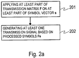
- FIG. 2 a shows a flowchart of a method 200 in accordance with an embodiment of the present invention.
- step 201 at least part of a transmission matrix is applied to at least one subset of the symbol vector s for forming processed symbols. If the whole transmission matrix F is applied on the whole symbols vector s the processed symbols are the vector Fs. Otherwise, only some columns of the transmission matrix F are applied on the relating elements of the symbol vector s. In this case, the processed symbols are some elements of the vector Fs.
- at least one transmission signal is generated based on said processed symbols.
- the transmission matrix F may be in accordance with the first or the second embodiment of the invention.
- FIG. 2 b shows a flowchart of a method 210 in accordance with a further embodiment of the present invention.
- the transmission matrix used in the method 210 may be in accordance with the first or the second embodiment of the invention.
- a transmission matrix F is determined. This step may involve, for example, selecting a transmitter specific constituent matrix from a set of available constituent matrices.
- correlation properties of the transmission matrix F are determined. The correlation properties can be determined using any known technique. Such techniques are known to one skilled in the art, and are therefore not discussed here in more detail.
- columns of the transmission matrix F are grouped into sets of correlating columns.
- the sets of correlating columns are associated with a plurality of users/receivers/information streams. One option is to associate each set of correlating matrix columns to one user. In this case the signals sent to other users do not interfere significantly with the signals sent to a specific user.
- a second option is to associate a set of correlating matrix columns to a set of users.
- the signals sent to this set of users typically interfere.
- the users belonging to this set should know all matrix columns used for sending information this set of users for being able to detect the symbols intended for them.
- a further option is to associate two or more sets of correlating matrix columns to a user, if the data rate required cannot be provided with only one set of correlating matrix columns.
- the number of transmission matrix columns (or, in other words, the number of symbols in the symbol vector s) is proportional to the data rate.
- receiver device complexity depends on how the sent signals are expected to be correlated with each other, it is possible to take into account receiver device complexity in transmitting signals. If a certain receiver device is known to have a low complexity, it may be associated with a set of transmission matrix columns that do no correlate with other transmission matrix columns that are currently in use. If another receiver device is known to be able to process interfering signals, this receiver device may be associated with matrix columns that correlate with matrix columns in use with other receiver devices.
- the method 210 continues with steps 201 and 202 . If the elements of the vector Fs are to be transmitted, for example, from a plurality of transmitter devices, it is possible to further process these processed symbols using transmitter-specific matrices in step 215 for separating transmissions from different transmitters. Thereafter the transmission signals are transmitted in step 216 .
- the correlation properties of the transmission matrix may be used in determining which columns of the transmission matrix F to use for which users/receiver/information streams.
- the correlation properties are typically determined off-line or on-line. Offline typically means using channel models.
- On-line means using estimated information on channel, for example, on delay spread L. The same L is used in designing the length of cyclic prefix prior art block transmission methods.
- FIG. 3 a shows, as an example, a block diagram of a transmitting device 10 where a transmission matrix F is applied.
- This device 10 transmits all elements of a symbol vector s, and it thus applies the whole transmission matrix F to the symbol vector s.
- the transmitting device 10 typically contains an encoder ENC 11 , and information streams (bits) coming from the encoder 11 are input to a modulator MOD 12 .
- the modulator may be, for example, a scalar, vector or matrix modulator.
- the output from this modulator is a sequence of consequent symbols.
- the symbols are input to a serial-to-parallel converter S/P 13 , where a symbol vector (an ordered set of symbols) is formed.
- the symbol vector is then input to a block modulation unit 14 , where the transmission matrix F is applied to the symbol vector.
- the transmission matrix F is applied to the symbol vector.
- pulse shaping functionality maybe placed before the antenna.
- the transmission signals are input to an antenna for transmission.
- the transmitting device 10 also contains the control unit 16 for associating the symbols/transmission matrix columns to users.
- This control unit 16 controls that the symbol vector and the block modulation unit 14 have symbols and transmission matrix columns in a corresponding order.
- the symbols and transmission matrix columns may be ordered based on correlation assessment.
- the control unit 16 furthermore controls that there is a correct number of symbols per each user in the symbol vector.
- the correlation properties of the transmission matrix may be taken into account in the control unit 16 .
- the control unit 16 may also be responsible for determining the transmission matrix.
- the transmission matrix may have a transmitter-specific constituent matrix F b .
- the transmission matrix may be time dependent by having either a time-dependent multiplier matrix F a or a time-dependent constituent matrix F b , or both.
- the transmitting device 10 may be, for example, a base station in a cellular communications network. In general, it may be any transmitting device configured to transmit signals to one or more receiving devices, including WLAN device or access point or Ultrawideband transmitter.
- FIG. 3 a shows, as examples, also block diagrams of two receiver devices 20 a and 20 b .
- the receiver device 20 a contains a receiver matrix unit 21 a , where a receiver matrix or columns or a receiver matrix are applied on received signals. It is appreciated that this unit may be implemented fully or in part with special algorithms or with corresponding implementations, such as using Fast Fourier Transform, or Fast Walsh Transform.
- the result is a vector of received signals, and it is input into a parallel-to-serial converter P/S 22 .
- the sequence of symbols is then input to a demodulator 23 which converts the symbols to bits.
- the received symbols are detected in a symbol detector 24 , which typically uses channel information in detection.
- the receiver matrix unit may use also various interference reduction methods or advanced detection methods, such as receiver matrices derived from minimum mean square error principle (known in the art) or some interference cancellation units, or sequence detection unit (such as Maximum A Posteriori (MAP) or Maximum Likelihood Sequence Estimate (MLSE) detector, or simplification thereof), or any approximate Maximum Likelihood detection method such as Sphere detection.
- these units may output hard or soft decisions. Thereafter the received symbols, or the corresponding hard or soft bits are decoded in the decoder 25 .
- the receiver matrix unit R 1 21 a in the receiving device 20 a contains information of at least those transmission matrix columns that are associated with this receiving device in the transmission. Alternatively, the receiver matrix unit R 1 21 a may contain information about all the transmission matrix columns. The receiver matrix unit R 1 21 a in the device 20 a may thus contain information about different transmission matrix columns than the receiver matrix unit R 2 21 b in the device 20 b . The receiving device 20 a may obtain information about the transmission matrix columns associated with it, for example, by receiving signalling information about the transmission matrix column allocation. The details of how to determine a receiver matrix based on information about a transmission matrix are clear to a skilled person.
- FIG. 3 b shows, as a further example, a block diagram of a transmitting device 10 a .
- the encoder 11 a and the modulator 12 a process parallel information streams.
- the parallel information streams at given time form a symbol vector.
- the parallel information streams from the modulator 12 a are fed into a plurality of block modulation units 14 a , 14 b , 14 c .
- Each of these transmission matrix blocks represents one column F j of a transmission matrix F.
- transmitting devices There may be, for example, a plurality of transmitting devices, each using a set of transmission matrix columns. These transmission devices may be, for example, mobile stations of a cellular communications system. In general, they may be any devices configured to transmit signals.
- FIGS. 3 a and 3 b are illustrative. The functionality of some or all units may be provided using a single piece of equipment. Typically the functionality is provided as a suitable combination of hardware and software.
- the receiver needs to know only its own transmission matrix columns, or the columns that are known to be interfering in the given channel with the transmission matrix columns associated with this receiver. As a comparative example, it is noted that in CDMA systems all transmission matrix columns need to be used for optimal reception. In an OFDM only one transmission matrix column. In accordance with embodiments of the present invention, the receiver needs to know only some transmission matrix columns, more specifically those transmission matrix columns that interfere most with the transmission matrix columns associated to this receiver. In some cases, blind receivers may be used where the receiver estimates receiver filters using measured quantities, such as interference correlation or covariance matrices. These receiver filters may be optimised in manner that is identical to those used, for example, in CDMA literature. Such filters may operate at symbol rate or at or above chip rate, where the chip rate is essentially the inverse of the time required to transmit a smallest unit (one element) of matrix F.
- the complexity of a receiver can be also adjusted by the selection of the matrices F a and F b and by the selection of the dimension of the identity matrix I.
- all transmitted symbols within a block may interfere with each other in a worst case. These symbols may relate to one user (in multicode transmission) or to many users. Comparing to a CDMA receiver, a receiver in accordance with embodiments of the present invention is less complex, since the receiver knows a priori which columns interfere with each other most.
- the sets of symbols to be sent may be sent from one transmitting device, for example from a base station. This means that the columns of the transmission matrix are all used in the base station.
- the sets of symbols may be sent from a set of antennas. It is possible that each set of processed symbols is sent from a separate antenna.
- the antennas may belong to one network element or transmitting device, or each antenna may belong to a respective transmitting device. It is, of course, also possible that some transmitting devices have only one antenna and some have more than one antenna. In this case, the number of the transmission matrix columns associated with each transmitting device typically equals the number of antennas in the respective transmitting device.
- the transmission matrix F in Equation 1 does not involve scrambling, which is typically used in communication systems for separating signals sent from different CDMA base station or other corresponding network elements It is possible to add scrambling after processing symbols using the transmission matrix F.
- Scrambling may be implemented, for example, as a transmitting-device-specific or antenna-specific diagonal matrix ⁇ j relating to scrambling.
- G j A j F.
- A may be an arbitary, unitary matrix.
- the transmission matrix as defined in connection with Equation 1 above is transmitting device or antenna specific.
- F j (F a I) F b,j , where there is defined a plurality of matrices F b,j .
- the transmission matrix F defined above in connection with Equation 1 may form a part of a combination matrix used for processing sets of symbols.
- the combination matrix may be a sum of the transmission matrix F and a further matrix.
- the further matrix typically relates to block based transmission.
- Some examples of block-based matrices that may be added up with a transmission matrix F are the following: matrix relating to orthogonal frequency division multiplexing, matrix relating to code division multiplexing, and matrix relating to chip-interleaved block-spread transmission.
- a combination matrix of a transmission matrix F and of a further matrix results in a combination matrix where many columns interfere in a transmission channel. Therefore, a reduced set of non-correlating columns may be selected from the combination matrix.
- a further modification is that there is defined a sequence of transmission matrices F, and that for consecutive blocks of symbols different transmission matrices are used in accordance with the defined transmission matrix sequence.
- the multiplier matrix F a is time dependent.
- the multiplier matrix F a is selected from a set of matrices forming a rotation, i.e. unitary of an orthogonal matrix.
- the present invention is applicable in any communication system where block-based transmission is used.
- the present invention may be applied in wireless local area networks (WLAN), DVB-T, Ultrawideband communications, to name a few examples.
- WLAN wireless local area networks
- the communication systems, where the present invention may be applicable are not restricted to SISO (single-input-single-output) systems.
- the invention may be applicable also in SIMO (single-output-multiple-input) systems, in MIMO (multiple-input-multiple-output), or in MISO (multiple-input-single-output) systems.
- Various diversity schemes may also be applicable together with the present invention.
- Different delay diversity concepts may be used, for example by sending delayed copies of transmitted signal from at least one antenna, by using the defined transmission matrix F as a basis matrix in multi-antenna block transmission methods, or in any method where block transmission is used in a multi-antenna channel.
- multi-antenna block transmission methods are discussed by A. Hottinen and O. Tirkkonen, “Precoder designs for high rate space-time block codes,” in Proc. Conference on Information Sciences and Systems 2004 (CISSI 2004), Princeton, N.J. USA, March 2004.
- the transmission matrix F that is a direct product of the multiplier matrix, the (optional) identity matrix, and the constituent matrix may be multiplied with unitary matrices before it is applied on the symbol vector.
- each transmitter of a plurality of transmitters may be using a set of columns of a transmission matrix F, where the constituent matrix F b is transmitter-specific.
- the effective transmission matrix of the whole system is representable as a block matrix, where the constituent matrix F b is replaced by a set of constituent block matrixes.
- These matrices may alternatively or in addition be time-specific, so that the matrices are different for different modulation blocks transmitted at different times.
- the matrices may be antenna-specific, so that different matrices at used in a different transmitter antenna or beam.
- a computer program as defined in the appended claims may be embodied on a record medium or stored in a memory of a computing device.
Abstract
Description
F=(F a
where Fa is a d2 dimensional square multiplier matrix, Fb is a d3 dimensional square constituent matrix and I is a d1/(d2d3) dimensional identity matrix. The notation
F=Fa
where Fa is a d2 dimensional square multiplier matrix and Fb is a d3 dimensional square constituent matrix. The dimension of the constituent matrix Fb is larger than 1, d3>1. The dimension of the multiplier matrix is larger than 1, d2>1. Furthermore, at least one of the entries of the multiplier matrix Fa is complex.
Here Fa is a unitary matrix, and (μ,ν)=(√{square root over (0.8)}, √{square root over (0.2)}) indicating power 0.8 for μ and 0.2 for ν. Fb above is a 2×2 Hadamard matrix. The transmission matrix F in this case is
In this case, the transmission matrix F becomes
Claims (61)
Applications Claiming Priority (2)
| Application Number | Priority Date | Filing Date | Title |
|---|---|---|---|
| FIFI20041311 | 2004-10-08 | ||
| FI20041311A FI20041311A0 (en) | 2004-10-08 | 2004-10-08 | Lohkomodulaatio |
Publications (2)
| Publication Number | Publication Date |
|---|---|
| US20060078063A1 US20060078063A1 (en) | 2006-04-13 |
| US7489736B2 true US7489736B2 (en) | 2009-02-10 |
Family
ID=33306012
Family Applications (1)
| Application Number | Title | Priority Date | Filing Date |
|---|---|---|---|
| US10/993,486 Expired - Fee Related US7489736B2 (en) | 2004-10-08 | 2004-11-22 | Block modulation |
Country Status (5)
| Country | Link |
|---|---|
| US (1) | US7489736B2 (en) |
| EP (1) | EP1797691B1 (en) |
| FI (1) | FI20041311A0 (en) |
| TW (1) | TW200625892A (en) |
| WO (1) | WO2006037835A1 (en) |
Cited By (7)
| Publication number | Priority date | Publication date | Assignee | Title |
|---|---|---|---|---|
| US20060140294A1 (en) * | 2004-11-05 | 2006-06-29 | Nokia Corporation | Block modulation |
| US20060285602A1 (en) * | 2005-06-16 | 2006-12-21 | Lg Electronics, Inc. | Method of transmitting/receiving OFDM signal and mobile communication terminal thereof |
| US20080260054A1 (en) * | 2006-08-17 | 2008-10-23 | Interdigital Technology Corporation | Method and apparatus for reducing a peak-to-average power ratio in a multiple-input multiple-output system |
| US20090180459A1 (en) * | 2008-01-16 | 2009-07-16 | Orlik Philip V | OFDMA Frame Structures for Uplinks in MIMO Networks |
| US20100278035A1 (en) * | 2009-05-04 | 2010-11-04 | Qual Comm Incorporated | Method and system for multi-user detection using two-stage processing |
| US9014111B2 (en) | 2011-08-10 | 2015-04-21 | Industrial Technology Research Institute | Multi-block radio access method and transmitter module and receiver module using the same |
| US20210334035A1 (en) * | 2019-07-17 | 2021-10-28 | Micron Technology, Inc. | Estimation of read level thresholds using a data structure |
Families Citing this family (11)
| Publication number | Priority date | Publication date | Assignee | Title |
|---|---|---|---|---|
| US8713623B2 (en) | 2001-09-20 | 2014-04-29 | Time Warner Cable Enterprises, LLC | Technique for effectively providing program material in a cable television system |
| EP1730856A4 (en) * | 2004-04-02 | 2012-05-02 | Nortel Networks Ltd | Space-time transmit diversity systems and methods for ofdm applications |
| US9723267B2 (en) * | 2004-12-15 | 2017-08-01 | Time Warner Cable Enterprises Llc | Method and apparatus for wideband distribution of content |
| FI20065438A0 (en) * | 2006-06-22 | 2006-06-22 | Nokia Corp | Disturbance Removal Unit and Disturbance Removal Procedure |
| US8509710B2 (en) * | 2007-02-06 | 2013-08-13 | Qualcomm Incorporated | MIMO transmission with explicit and implicit cyclic delays |
| US8780771B2 (en) * | 2007-02-06 | 2014-07-15 | Qualcomm Incorporated | Cyclic delay diversity and precoding for wireless communication |
| US8422582B2 (en) | 2007-09-20 | 2013-04-16 | France Telecom | Method for sending and receiving a signal in a multiple-antenna system implementing spatial pre-encoding, corresponding sender, receiver and computer program products |
| US20100119017A1 (en) * | 2008-11-10 | 2010-05-13 | Joonsuk Kim | Method and system for a 4x2 sfbc/stbc system with 2 spatial streams using angle feedback |
| US9185341B2 (en) | 2010-09-03 | 2015-11-10 | Time Warner Cable Enterprises Llc | Digital domain content processing and distribution apparatus and methods |
| US20140105315A1 (en) * | 2012-10-12 | 2014-04-17 | The Governors Of The University Of Alberta | Frequency time block modulation for mitigating doubly-selective fading |
| CN103795489B (en) * | 2012-10-29 | 2017-05-24 | 电信科学技术研究院 | Method, system and device for transmitting coding indication information and determining precoding matrix |
Citations (7)
| Publication number | Priority date | Publication date | Assignee | Title |
|---|---|---|---|---|
| US5940445A (en) * | 1996-05-31 | 1999-08-17 | Motorola, Inc. | Method and apparatus for providing transmit diversity in a wireless communication system |
| US20020126740A1 (en) | 2001-03-08 | 2002-09-12 | Giannakis Georgios B. | Chip-interleaved, block-spread multi-user communication |
| US20050147180A1 (en) * | 2000-05-17 | 2005-07-07 | Ionescu Dumitru M. | Apparatus, and associated method, for forming a signal exhibiting space-time redundancy |
| US20050157807A1 (en) * | 2004-01-20 | 2005-07-21 | Lg Electronics Inc. | Method for transmitting/receiving signal in MIMO system |
| US20060045201A1 (en) * | 2004-08-27 | 2006-03-02 | Samsung Electronics Co., Ltd. | Apparatus and method for full-diversity, full-rate space-time block coding for two transmit antennas |
| US20060140294A1 (en) * | 2004-11-05 | 2006-06-29 | Nokia Corporation | Block modulation |
| US7227905B2 (en) * | 2001-09-18 | 2007-06-05 | Lucent Technologies Inc. | Open-loop diversity technique for systems employing multi-transmitter antennas |
Family Cites Families (4)
| Publication number | Priority date | Publication date | Assignee | Title |
|---|---|---|---|---|
| US8290098B2 (en) * | 2001-03-30 | 2012-10-16 | Texas Instruments Incorporated | Closed loop multiple transmit, multiple receive antenna wireless communication system |
| JP3902990B2 (en) * | 2002-07-02 | 2007-04-11 | キヤノン株式会社 | Hadamard transform processing method and apparatus |
| FR2848747A1 (en) * | 2002-12-16 | 2004-06-18 | France Telecom | Pre-coded signal emitting process for wireless communication system, involves interlacing pre-coded transmitted symbols to modify temporal order of symbols and coding each block of symbols according to coding time space |
| DE60327659D1 (en) * | 2003-03-28 | 2009-06-25 | Ntt Docomo Inc | FILTER PROCESS FOR TRANSMITTING IN ORTHOGONAL FREQUENCY MULTIPLEX COMMUNICATION SYSTEMS AND CORRESPONDING FILTER DEVICE |
-
2004
- 2004-10-08 FI FI20041311A patent/FI20041311A0/en not_active Application Discontinuation
- 2004-11-22 US US10/993,486 patent/US7489736B2/en not_active Expired - Fee Related
-
2005
- 2005-07-28 WO PCT/FI2005/000344 patent/WO2006037835A1/en active Application Filing
- 2005-07-28 EP EP05771110.3A patent/EP1797691B1/en not_active Not-in-force
- 2005-10-07 TW TW094135089A patent/TW200625892A/en unknown
Patent Citations (7)
| Publication number | Priority date | Publication date | Assignee | Title |
|---|---|---|---|---|
| US5940445A (en) * | 1996-05-31 | 1999-08-17 | Motorola, Inc. | Method and apparatus for providing transmit diversity in a wireless communication system |
| US20050147180A1 (en) * | 2000-05-17 | 2005-07-07 | Ionescu Dumitru M. | Apparatus, and associated method, for forming a signal exhibiting space-time redundancy |
| US20020126740A1 (en) | 2001-03-08 | 2002-09-12 | Giannakis Georgios B. | Chip-interleaved, block-spread multi-user communication |
| US7227905B2 (en) * | 2001-09-18 | 2007-06-05 | Lucent Technologies Inc. | Open-loop diversity technique for systems employing multi-transmitter antennas |
| US20050157807A1 (en) * | 2004-01-20 | 2005-07-21 | Lg Electronics Inc. | Method for transmitting/receiving signal in MIMO system |
| US20060045201A1 (en) * | 2004-08-27 | 2006-03-02 | Samsung Electronics Co., Ltd. | Apparatus and method for full-diversity, full-rate space-time block coding for two transmit antennas |
| US20060140294A1 (en) * | 2004-11-05 | 2006-06-29 | Nokia Corporation | Block modulation |
Non-Patent Citations (4)
| Title |
|---|
| Hottinen et al, "Precoder Designs for High Rate Space-Time Block Codes", 2004 Conference on Information Sciences and Systems, Pinceton University, Mar. 17-19, 2004. |
| Hottinen, et al., "Multiuser Scheduling with Matrix Modulation", IEEE International Symposium on Signal Processing and Information/Technology, Dec. 2003, pp. 5-8. |
| Terry, J., "Layered Matrix Modulation", IEEE Radio and Wireless Conference, Sep. 19-22, 2004, ISBN: 0-7803-8451-2, XP-10764560, pp. 107-110. |
| Zhou et al, "Chip-Interleaved Block-Spread Code Division Multiple Access", IEEE Transactions on Communications, vol. 50, No. 2, Feb. 2002, pp. 235-248. |
Cited By (9)
| Publication number | Priority date | Publication date | Assignee | Title |
|---|---|---|---|---|
| US20060140294A1 (en) * | 2004-11-05 | 2006-06-29 | Nokia Corporation | Block modulation |
| US20060285602A1 (en) * | 2005-06-16 | 2006-12-21 | Lg Electronics, Inc. | Method of transmitting/receiving OFDM signal and mobile communication terminal thereof |
| US20080260054A1 (en) * | 2006-08-17 | 2008-10-23 | Interdigital Technology Corporation | Method and apparatus for reducing a peak-to-average power ratio in a multiple-input multiple-output system |
| US20090180459A1 (en) * | 2008-01-16 | 2009-07-16 | Orlik Philip V | OFDMA Frame Structures for Uplinks in MIMO Networks |
| US20100278035A1 (en) * | 2009-05-04 | 2010-11-04 | Qual Comm Incorporated | Method and system for multi-user detection using two-stage processing |
| US8599677B2 (en) * | 2009-05-04 | 2013-12-03 | Qualcomm Incorporated | Method and system for multi-user detection using two-stage processing |
| US9014111B2 (en) | 2011-08-10 | 2015-04-21 | Industrial Technology Research Institute | Multi-block radio access method and transmitter module and receiver module using the same |
| US20210334035A1 (en) * | 2019-07-17 | 2021-10-28 | Micron Technology, Inc. | Estimation of read level thresholds using a data structure |
| US11789640B2 (en) * | 2019-07-17 | 2023-10-17 | Micron Technology, Inc. | Estimation of read level thresholds using a data structure |
Also Published As
| Publication number | Publication date |
|---|---|
| US20060078063A1 (en) | 2006-04-13 |
| EP1797691A1 (en) | 2007-06-20 |
| TW200625892A (en) | 2006-07-16 |
| WO2006037835A1 (en) | 2006-04-13 |
| FI20041311A0 (en) | 2004-10-08 |
| EP1797691B1 (en) | 2014-01-22 |
| EP1797691A4 (en) | 2011-11-02 |
Similar Documents
| Publication | Publication Date | Title |
|---|---|---|
| EP1797691B1 (en) | Block modulation | |
| US20060140294A1 (en) | Block modulation | |
| AU2019200710B2 (en) | Multi-user code division multiple access communication method, and corresponding transmitter and receiver | |
| JP4668925B2 (en) | Broadcast transmission by spatial spreading in multi-antenna communication systems | |
| US8345790B2 (en) | Method and apparatus for transmission within a multi-carrier communication system | |
| US9693339B2 (en) | Code division multiplexing in a single-carrier frequency division multiple access system | |
| US8130857B2 (en) | Method and apparatus for pilot multiplexing in a wireless communication system | |
| US8619920B2 (en) | Two-dimensional code spreading for interleaved FDMA system | |
| JP5016597B2 (en) | Method for transmitting and receiving signals with distributed training symbols in a mobile communication system | |
| US20060291431A1 (en) | Novel pilot sequences and structures with low peak-to-average power ratio | |
| US7120201B2 (en) | Method and system for optimization of channel estimation and synchronization in an OFDM-MIMO wireless communication system | |
| US7885316B2 (en) | Emission for CDMA communications systems on the MIMO channel | |
| US20070036068A1 (en) | Two-dimensional spreading method for an OFDM-CDM system | |
| KR100849338B1 (en) | Apparatus and method for coding/decoding of sttd in ofdm mobile communication system | |
| Wang et al. | Block precoding for MUI/ISI-resilient generalized multicarrier CDMA with multirate capabilities | |
| CN101577968B (en) | Method, system and device for obtaining descending channel information | |
| KR20110079755A (en) | Multi-user mimo system, receiver apparatus and transmitter apparatus | |
| US20070165705A1 (en) | Method of enhancing frequency diversity in block cdma systems | |
| KR20080071065A (en) | Transmit diversity method for mc-cdma | |
| KR101019172B1 (en) | Apparatus and method for data transmission/receiving in an v-blast orthogonal frequency division multiple system | |
| Azim | Performance of Single User vs. Multiuser Modulation in Wireless Multicarrier (MC) Communications | |
| Punnoose et al. | Layered space frequency equalisation for MIMO-MC-CDMA systems in frequency selective fading channels | |
| Boonkajay et al. | Generalized Frequency-Domain Filtered Single-Carrier Signal Transmission | |
| Cosovic et al. | Performance of Multi-Carrier Spread-Spectrum Systems with Spatial Diversity and Pre-Equalization | |
| Vakili et al. | A new scheme for signal reception in MC-CDMA systems with space-time block coding |
Legal Events
| Date | Code | Title | Description |
|---|---|---|---|
| AS | Assignment |
Owner name: NOKIA CORPORATION, FINLAND Free format text: ASSIGNMENT OF ASSIGNORS INTEREST;ASSIGNOR:HOTTINEN, ARI;REEL/FRAME:016022/0275 Effective date: 20041115 |
|
| FEPP | Fee payment procedure |
Free format text: PAYOR NUMBER ASSIGNED (ORIGINAL EVENT CODE: ASPN); ENTITY STATUS OF PATENT OWNER: LARGE ENTITY |
|
| STCF | Information on status: patent grant |
Free format text: PATENTED CASE |
|
| FPAY | Fee payment |
Year of fee payment: 4 |
|
| AS | Assignment |
Owner name: NOKIA TECHNOLOGIES OY, FINLAND Free format text: ASSIGNMENT OF ASSIGNORS INTEREST;ASSIGNOR:NOKIA CORPORATION;REEL/FRAME:035495/0924 Effective date: 20150116 |
|
| FPAY | Fee payment |
Year of fee payment: 8 |
|
| AS | Assignment |
Owner name: OMEGA CREDIT OPPORTUNITIES MASTER FUND, LP, NEW YORK Free format text: SECURITY INTEREST;ASSIGNOR:WSOU INVESTMENTS, LLC;REEL/FRAME:043966/0574 Effective date: 20170822 Owner name: OMEGA CREDIT OPPORTUNITIES MASTER FUND, LP, NEW YO Free format text: SECURITY INTEREST;ASSIGNOR:WSOU INVESTMENTS, LLC;REEL/FRAME:043966/0574 Effective date: 20170822 |
|
| AS | Assignment |
Owner name: WSOU INVESTMENTS, LLC, CALIFORNIA Free format text: ASSIGNMENT OF ASSIGNORS INTEREST;ASSIGNOR:NOKIA TECHNOLOGIES OY;REEL/FRAME:043953/0822 Effective date: 20170722 |
|
| AS | Assignment |
Owner name: BP FUNDING TRUST, SERIES SPL-VI, NEW YORK Free format text: SECURITY INTEREST;ASSIGNOR:WSOU INVESTMENTS, LLC;REEL/FRAME:049235/0068 Effective date: 20190516 |
|
| AS | Assignment |
Owner name: WSOU INVESTMENTS, LLC, CALIFORNIA Free format text: RELEASE BY SECURED PARTY;ASSIGNOR:OCO OPPORTUNITIES MASTER FUND, L.P. (F/K/A OMEGA CREDIT OPPORTUNITIES MASTER FUND LP;REEL/FRAME:049246/0405 Effective date: 20190516 |
|
| FEPP | Fee payment procedure |
Free format text: MAINTENANCE FEE REMINDER MAILED (ORIGINAL EVENT CODE: REM.); ENTITY STATUS OF PATENT OWNER: LARGE ENTITY |
|
| LAPS | Lapse for failure to pay maintenance fees |
Free format text: PATENT EXPIRED FOR FAILURE TO PAY MAINTENANCE FEES (ORIGINAL EVENT CODE: EXP.); ENTITY STATUS OF PATENT OWNER: LARGE ENTITY |
|
| STCH | Information on status: patent discontinuation |
Free format text: PATENT EXPIRED DUE TO NONPAYMENT OF MAINTENANCE FEES UNDER 37 CFR 1.362 |
|
| FP | Lapsed due to failure to pay maintenance fee |
Effective date: 20210210 |
|
| AS | Assignment |
Owner name: OT WSOU TERRIER HOLDINGS, LLC, CALIFORNIA Free format text: SECURITY INTEREST;ASSIGNOR:WSOU INVESTMENTS, LLC;REEL/FRAME:056990/0081 Effective date: 20210528 |
|
| AS | Assignment |
Owner name: WSOU INVESTMENTS, LLC, CALIFORNIA Free format text: RELEASE BY SECURED PARTY;ASSIGNOR:TERRIER SSC, LLC;REEL/FRAME:056526/0093 Effective date: 20210528 |