US7487566B2 - Adhesive roller - Google Patents
Adhesive roller Download PDFInfo
- Publication number
- US7487566B2 US7487566B2 US10/842,871 US84287104A US7487566B2 US 7487566 B2 US7487566 B2 US 7487566B2 US 84287104 A US84287104 A US 84287104A US 7487566 B2 US7487566 B2 US 7487566B2
- Authority
- US
- United States
- Prior art keywords
- adhesive
- roller
- backing layer
- release coating
- strip
- Prior art date
- Legal status (The legal status is an assumption and is not a legal conclusion. Google has not performed a legal analysis and makes no representation as to the accuracy of the status listed.)
- Active, expires
Links
Images


Classifications
-
- A—HUMAN NECESSITIES
- A47—FURNITURE; DOMESTIC ARTICLES OR APPLIANCES; COFFEE MILLS; SPICE MILLS; SUCTION CLEANERS IN GENERAL
- A47L—DOMESTIC WASHING OR CLEANING; SUCTION CLEANERS IN GENERAL
- A47L25/00—Domestic cleaning devices not provided for in other groups of this subclass
- A47L25/005—Domestic cleaning devices not provided for in other groups of this subclass using adhesive or tacky surfaces to remove dirt, e.g. lint removers
-
- A—HUMAN NECESSITIES
- A47—FURNITURE; DOMESTIC ARTICLES OR APPLIANCES; COFFEE MILLS; SPICE MILLS; SUCTION CLEANERS IN GENERAL
- A47L—DOMESTIC WASHING OR CLEANING; SUCTION CLEANERS IN GENERAL
- A47L25/00—Domestic cleaning devices not provided for in other groups of this subclass
- A47L25/08—Pads or the like for cleaning clothes
-
- Y—GENERAL TAGGING OF NEW TECHNOLOGICAL DEVELOPMENTS; GENERAL TAGGING OF CROSS-SECTIONAL TECHNOLOGIES SPANNING OVER SEVERAL SECTIONS OF THE IPC; TECHNICAL SUBJECTS COVERED BY FORMER USPC CROSS-REFERENCE ART COLLECTIONS [XRACs] AND DIGESTS
- Y10—TECHNICAL SUBJECTS COVERED BY FORMER USPC
- Y10T—TECHNICAL SUBJECTS COVERED BY FORMER US CLASSIFICATION
- Y10T428/00—Stock material or miscellaneous articles
- Y10T428/14—Layer or component removable to expose adhesive
- Y10T428/1452—Polymer derived only from ethylenically unsaturated monomer
- Y10T428/1457—Silicon
-
- Y—GENERAL TAGGING OF NEW TECHNOLOGICAL DEVELOPMENTS; GENERAL TAGGING OF CROSS-SECTIONAL TECHNOLOGIES SPANNING OVER SEVERAL SECTIONS OF THE IPC; TECHNICAL SUBJECTS COVERED BY FORMER USPC CROSS-REFERENCE ART COLLECTIONS [XRACs] AND DIGESTS
- Y10—TECHNICAL SUBJECTS COVERED BY FORMER USPC
- Y10T—TECHNICAL SUBJECTS COVERED BY FORMER US CLASSIFICATION
- Y10T428/00—Stock material or miscellaneous articles
- Y10T428/14—Layer or component removable to expose adhesive
- Y10T428/1476—Release layer
Definitions
- the present invention relates generally to adhesive rollers of the type used for detritus removal.
- rollers used for detritus removal typically comprise an elongated strip having a backing layer.
- the strip includes two ends and two spaced apart and parallel sides.
- An adhesive layer is provided along a first side of the backing layer. Thereafter, the strip is wound into a tubular and cylindrical roller with the adhesive layer facing outwardly. Oftentimes the strip is wound around a tubular core and the tubular core is then rotatably mounted on a handle to facilitate rolling of the adhesive roller along the surface desired to be cleaned.
- the adhesive on the outermost adhesive layer or sheet of the adhesive roller becomes covered with detritus and other matter and loses its adhesiveness. When this happens, it is necessary to remove the outermost sheet of the adhesive roller to expose fresh adhesive on the next underlying sheet on the roller.
- a still further disadvantage of the previously known adhesive rollers is that it is difficult during the manufacturing process to maintain an accurate width of the dry edge along one or both of the edges of the strip.
- the inability to maintain an accurate and predetermined dimension for the width of the dry edges along the adhesive roller provides an aesthetically displeasing appearance for the consumer.
- zone coating of the adhesive on the backing layer to form the dry edge(s) significantly increases the manufacturing costs for the adhesive roller.
- the present invention provides an adhesive roller which overcomes all of the above-mentioned disadvantages of the previously known devices.
- the adhesive roller of the present invention comprises an elongated strip having a backing layer constructed of any conventional material, such as paper, film, foam or cloth.
- the strip includes two ends and two spaced apart and generally parallel sides.
- An adhesive coating is then applied across all or substantially all of a first or outer side of the backing layer.
- an adhesive release coating covers at least a portion of a second or inner side of the backing layer and this release coating has a release strength which varies laterally across the strip. Consequently, after the strip is wound into a cylindrical roller with the adhesive layer facing outwardly, the adhesive release coating between the backing layer and the next inner adhesive sheet reduces the adhesion between the backing layer and the next inner adhesive sheet thus allowing the sheets to easily separate from the roller when desired. Some adhesion, however, between the backing layer and the next inner adhesive sheet is necessary in order to maintain the integrity of the roller in use.
- the adhesive release coating may take any of several embodiments.
- a strong adhesive release coating which provides minimal adhesion is provided only along the edges of the inner side of the backing layer.
- the strong adhesive release coating may overlie the conventional weak adhesive release coating or, alternatively, zone coating for both the strong and weak adhesive release coatings may be used to selectively cover portions.
- the adhesive release coating prevents the edges of the roller from adhering together thus allowing the edges to be easily grasped to initiate the removal of individual sheets from the adhesive roller. Furthermore, this is accomplished even though the entire outwardly facing surface of the roller is covered with adhesive for maximum cleaning efficiency.
- the strong adhesive release coating is applied to the inner side of the backing layer in a pattern.
- This pattern may be either constant, i.e. covering a same percentage of the inner side of the backing layer across the entire surface of the backing layer, or may be laterally varied to alter the adhesion between the backing layer and the next inner adhesive layer.
- the adhesive release coating is applied across the center of the backing layer so that the adhesive release coating covers only a relatively small percentage of the area of the center of the backing layer. In doing so, a relatively firm, but removable, adhesion is achieved between the center of the backing layer and the next innermost adhesive layer.
- the percent of coverage of the strong adhesive release coating is increased from the center of the strip towards its edges thus decreasing the adhesion between the backing layer and the next inner adhesive layer along the edges of the strip.
- different adhesive release coatings of different strengths may be provided to different portions of the inner side of the backing layer by zone coating or by laying adhesive release coatings on top of each other.
- an adhesive release coating of only minimal effectiveness may be provided along the center of the backing layer while an adhesive release coating which is much more effective, and thus results in less adhesion between the backing layer and the next innermost adhesive layer, is provided along the edges of the backing strip.
- the backing layer is mechanically crimped or embossed, either along its entire surface or in a pattern, thus providing alternating peaks and valleys along the backing layer. These peaks and valleys thus reduce the area of contact, and thus the adhesion, of the inner side of the backing layer with the next inner adhesive layer of the roller.
- Such crimping may be done in a lateral, longitudinal or a combination lateral and longitudinal pattern to provide different levels of adhesion between the backing strip and the next inner adhesive layer.
- a solid substrate is positioned along the inner side of the backing layer to vary the adhesion between the backing layer and the next inner adhesive layer.
- a tab is formed on the backing layer at intervals corresponding to a single revolution around the roll.
- a strong adhesive release coating is applied to the inside surface of the tab so that the tab exhibits little, if any, adhesion to the underlying surface. Consequently, in use the tab “pops up” from the roll and forms a convenient pull tab for initiating the removal of individual sheets from the roll when desired.
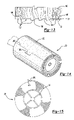
- FIG. 1 is an elevational view illustrating a preferred embodiment of the present invention
- FIG. 2 is a sectional view taken substantially along line 2 - 2 in FIG. 1 ;
- FIG. 3 is a plan view of a preferred embodiment of the invention prior to winding into a roller construction
- FIG. 4 is a sectional view taken substantially along line 4 - 4 in FIG. 1 ;
- FIG. 5 is a plan view of the second or innermost side of the backing strip illustrating a first preferred embodiment of the present invention
- FIG. 6 is a view similar to FIG. 5 but illustrating a modification thereof
- FIG. 7 is a view similar to FIG. 5 but illustrating a modification thereof
- FIG. 8 is a view similar to FIG. 5 but illustrating a still further embodiment thereof.
- FIG. 9 is a view taken substantially along line 9 - 9 in FIG. 8 ;
- FIG. 10 is a plan view illustrating still a further embodiment of the present invention.
- FIG. 11 is a sectional view taken substantially along line 11 - 11 in FIG. 10 and enlarged for clarity;
- FIG. 12 is a view similar to FIG. 4 , but illustrating a modification thereof;
- FIG. 13 is a view similar to FIG. 9 , but showing a modification thereof;
- FIG. 14 is a view similar to FIG. 1 , but illustrating a modification thereof.
- FIG. 15 is a view similar to FIG. 2 , but illustrating a modification thereof.
- the roller 20 is tubular and cylindrical in shape.
- the roller 20 preferably includes a tubular and cylindrical core 24 made of cardboard, plastic or other suitable material.
- the core 24 is then mounted on a handle 26 ( FIG. 1 ) so that the adhesive roller 20 rotates freely with respect to the handle 26 .
- the adhesive roller 20 comprises an elongated strip 28 having a first end 30 , a second end 32 , and two spaced apart and generally parallel sides 34 .
- the strip 28 includes a backing layer 39 having a first or outer side 36 and second or inner side 38 .
- the backing layer 39 may be constructed of any conventional material, such as paper. Additionally, the backing layer 39 may be made of paper, film, cloth, foam as well as other materials and mixtures thereof. In the event that the backing layer 39 is made of a porous material, such as paper, the backing layer is preferably saturated and/or sealed with a conventional sealant, such as a water-based latex sealant or solvent-based sealant.
- An adhesive layer 40 is coated onto the first side 36 of the backing layer 39 50 that the adhesive layer 40 substantially covers the entire first side 36 of the backing layer 39 . Any adhesive may be used for the adhesive layer 40 .
- An adhesive release coating 42 is also applied, in a fashion to be subsequently described in greater detail, along the second side 38 of the backing layer 39 such that the release coating 42 has a strength which varies laterally across the backing layer 39 .
- the adhesive release coating 42 may be of any conventional composition, but preferably comprises a material selected from the group of fluoropolymers, silicone, wax, lacquer, paint, ink, soap, oil and mixtures thereof.
- the adhesive release coating 42 reduces the adhesion between the second side 38 of the backing layer 39 and the adhesive 40 on the next inner layer of the roller 20 .
- the adhesive release coating 42 is preferably in liquid form as it is applied to the backing layer 39 and is preferably applied by zone coating although other coating methods may alternatively be used. However, unlike the previously known zone coating of the adhesive, high accuracy of zone coating the adhesive release coating is not required for aesthetic reasons since the adhesive release coating 42 is hidden while on the roll and not visible on the sheets when removed.
- the strip 28 After application of both the adhesive layer 40 to the first or outer side 36 of the backing layer 39 and the release coating 42 to the second or inner side 38 of the backing layer 39 , the strip 28 is wound into the cylindrical roller 20 illustrated in FIGS. 1 and 2 so that the adhesive layer 40 faces outwardly. In doing so, the strip 28 forms a plurality of overlying layers of the strip 28 as best shown in FIG. 2 .
- each layer or revolution of the strip 28 on the roller 20 forms a single sheet on the adhesive roller 20 .
- Conventional perforations 44 are provided at spaced intervals along the strip 28 corresponding to substantially one revolution of the strip 28 around the roller 22 . Consequently, individual sheets from the strip 28 may be removed by ripping the sheet along the perforations in the desired fashion to expose the fresh adhesive on the next underlying inner sheet.
- a cut or series of cuts are formed in the roller construct 20 after it is wound into a roll in order to achieve easy separation of individual sheets from the roller 20 .
- the strip is spiral wound around the roller 20 , the removal of one spiral winding of the strip exposes fresh adhesive around the outer surface of the roller 20 .
- a highly effective adhesive release coating 42 i.e. an adhesive release coating which minimizes or eliminates adhesion
- a central portion 50 of the second side 38 of the backing layer 39 remains free of the highly effective adhesive release coating thereby relying entirely upon the inherent release quality of the backing layer 39 or, alternatively, is coated with a less effective adhesive release coating which reduces adhesion by an amount less than the highly effective release coating, but in an amount sufficient to minimize or eliminate shredding during removal of individual sheets from the roller 20 . Consequently, when the strip illustrated in FIG. 5 is rolled into the cylindrical roller 20 illustrated in FIGS.
- the adhesive release coating 42 prevents, or at least minimizes, adhesion of the backing layer 39 to the adhesive on the next inner layer of the roller 20 thus allowing the edges of the strip 28 to be easily grasped and separated from each other for individual sheet removal from the roller 20 when desired.
- the highly effective adhesive release coating 42 is not applied to the central portion 52 of the backing strip 39 , the adhesion between the central portion 52 of the backing strip 39 and the adhesive layer on the next inner sheet of the roller 20 maintains the integrity of the adhesive roller 20 in use.
- FIG. 6 a still further embodiment of the present invention is there shown in which the highly effective adhesive release coating 42 is applied to the second side 38 of the backing layer 39 in a pattern 56 such that the adhesive release coating 42 covers only a portion of the area of the second side 38 of the backing layer 39 . Consequently, the greater percentage of coverage of the adhesive release coating 42 along any given portion of the backing layer 39 reduces the adhesion between the backing layer 39 and the adhesive layer on the next inner sheet of the roller 20 , and vice versa.
- the circular pattern 56 for the adhesive release coating 42 illustrated in FIG. 6 is for exemplary purposes only.
- the pattern 56 may be of any desired shape or configuration and may be either a repetitive pattern, as illustrated in FIG. 6 , a gradated pattern, or a completely random pattern.
- the pattern 56 of the adhesive release coating 42 may be either constant across the entire second side 34 of the backing layer 39 or, as shown, may vary in area coverage laterally across the backing layer 39 .
- the degree of adhesion between the backing layer 39 and the adhesive layer on the next inner sheet may be varied as desired.
- the area of coverage of the pattern 56 is preferably higher along the edges 34 of the backing layer 39 than in the center to facilitate removal of individual sheets from the roller 20 while maintaining good adhesion along the center of the roller to ensure the integrity of the roller during use.
- the adhesive release coating 42 may be applied directly to the second side 34 of the backing layer 39 , or alternatively, may be applied over an underlying coat or coats 43 of an adhesive release material of a different strength.
- a still further embodiment of the present invention is shown in which a first adhesive release coating 42 ′ is provided along predetermined portions of the second side 38 of the backing layer 39 while a second and different adhesive release coating 42 ′′ is provided along other portions of the backing layer 39 .
- the adhesive release coating 42 ′ of a first release efficacy is provided along both edges while the second adhesive release coating 42 ′′ of a different release efficacy is provided along the center of the backing layer 39 .
- the use of different types of adhesive release coatings varies the degree of adhesion between the backing layer 39 and the adhesive layer on the next inner sheet of the roller 20 to facilitate easy removal of the sheets from the roller 20 when desired, while maintaining the integrity of the roller 20 in use.
- the release coatings 42 , 42 ′ and/or 42 ′′ may be color tinted and thus visible to the user. The same, or different, color of tinting may be used for the different release coatings 42 , 42 ′ and 42 ′′.
- the release coating 42 , 42 ′ and/or 42 ′′ may be selectively tinted to form visible indicia, such as a company name or trademark. Such a company name or trademark may also, or alternatively, be printed onto the release coating 42 , 42 ′ and/or 42 ′′.
- a tab 200 is formed through the backing layer at intervals corresponding to one revolution of the roller 20 .
- the tab 200 protrudes outwardly from the perforation or cut line 202 formed through the strip to facilitate the removal of individual sheets from the roller 20 .
- a highly effective adhesive release coating 204 is applied to the inner side of the tab 200 so that the tab 200 exhibits little, if any, adhesion to the underlying layer on the roller 20 . Consequently, the tab 200 “pops up” from the roller 20 and forms a pull tab to facilitate the removal of individual sheets from the roller 20 .
- the highly effective release coating may be applied in a continuous step on the underside of the roller such that the strip is aligned with the tabs 200 .
- portions 60 of the backing layer 39 are deformed by crimping to form alternating peaks 62 and valleys 64 ( FIG. 9 ) along the backing layer 39 . Consequently, when the strip 28 is wound into the cylindrical roller illustrated in FIGS. 1 and 2 , the crimped portions 60 of the backing layer 39 reduce the area of contact between each layer or sheet of the backing layer 39 with the adhesive layer on the next inner sheet of the roller 20 . By reducing and controlling the area of contact between the backing layer 39 and the adhesive layer on the next inner sheet, the degree of adhesion between adjacent layers or sheets on the adhesive roller 22 can be varied laterally across the strip 28 as desired between the sides 34 of the strip 28 .
- a center portion 66 of the backing strip 39 is left uncrimped, or only partially crimped, to increase the strength of the adhesion between the center portion 66 of the backing layer 39 and the adhesive layer on the next inner roller in order to ensure integrity of the roller 20 during use.
- the degree of crimping of the backing layer 39 may be maintained constant laterally across the backing layer 39 or may be varied as previously described. Additionally, an adhesive release coating may optionally be used in conjunction with the crimped portions 60 of the backing strip 39 .
- the backing layer 39 is made of film or similar material by an extrusion process.
- the extruded backing layer passes through an embossing roller 100 which embosses the backing layer 39 into alternating peaks 102 and valleys 104 so that the area of contact with the second side 42 of the backing layer 39 with the adhesive layer 40 on the next inner sheet of the roller varies in proportion with the area of contact between the peaks 102 and the adhesive layer 40 .
- the area of contact may be varied to produce minimal adhesion, as shown at areas 106 , and stronger adhesion, as shown at area 108 .
- the adhesive release coating is in liquid form and applied to the second surface of the backing layer by zone coating.
- a solid adhesive release substrate 90 may be applied to the second side 38 of the backing layer 39 as shown in FIGS. 10 and 11 .
- Such a release substrate 90 may be applied to selected portions of the backing layer 39 or, alternatively, may be applied in a pattern such as along the edges as shown in FIGS. 10 and 11 .
- the backing layer 38 may be deformed by embossing to form a pattern of peaks and valleys on the backing layer. Such embossment is particularly advantageous when the backing layer is a film.
- the present invention provides an adhesive roller for detritus removal which advantageously provides increased efficiency of the adhesive roller since the outermost surface of the adhesive roller is completely covered with an adhesive.
- the present invention achieves this while still maintaining easy removal of individual sheets from the adhesive roller.
Abstract
Description
Claims (14)
Priority Applications (4)
| Application Number | Priority Date | Filing Date | Title |
|---|---|---|---|
| US10/842,871 US7487566B2 (en) | 2003-09-04 | 2004-05-11 | Adhesive roller |
| MXPA04008645A MXPA04008645A (en) | 2003-09-04 | 2004-09-03 | Adhesive roller. |
| CA2480201A CA2480201C (en) | 2003-09-04 | 2004-09-03 | Adhesive roller |
| US12/106,595 US7673363B2 (en) | 2003-09-04 | 2008-04-21 | Adhesive roller |
Applications Claiming Priority (2)
| Application Number | Priority Date | Filing Date | Title |
|---|---|---|---|
| US10/655,101 US20050050660A1 (en) | 2003-09-04 | 2003-09-04 | Adhesive roller |
| US10/842,871 US7487566B2 (en) | 2003-09-04 | 2004-05-11 | Adhesive roller |
Related Parent Applications (1)
| Application Number | Title | Priority Date | Filing Date |
|---|---|---|---|
| US10/655,101 Continuation-In-Part US20050050660A1 (en) | 2003-09-04 | 2003-09-04 | Adhesive roller |
Related Child Applications (1)
| Application Number | Title | Priority Date | Filing Date |
|---|---|---|---|
| US12/106,595 Division US7673363B2 (en) | 2003-09-04 | 2008-04-21 | Adhesive roller |
Publications (2)
| Publication Number | Publication Date |
|---|---|
| US20050050661A1 US20050050661A1 (en) | 2005-03-10 |
| US7487566B2 true US7487566B2 (en) | 2009-02-10 |
Family
ID=34279083
Family Applications (2)
| Application Number | Title | Priority Date | Filing Date |
|---|---|---|---|
| US10/842,871 Active 2025-03-05 US7487566B2 (en) | 2003-09-04 | 2004-05-11 | Adhesive roller |
| US12/106,595 Expired - Fee Related US7673363B2 (en) | 2003-09-04 | 2008-04-21 | Adhesive roller |
Family Applications After (1)
| Application Number | Title | Priority Date | Filing Date |
|---|---|---|---|
| US12/106,595 Expired - Fee Related US7673363B2 (en) | 2003-09-04 | 2008-04-21 | Adhesive roller |
Country Status (3)
| Country | Link |
|---|---|
| US (2) | US7487566B2 (en) |
| CA (1) | CA2480201C (en) |
| MX (1) | MXPA04008645A (en) |
Cited By (4)
| Publication number | Priority date | Publication date | Assignee | Title |
|---|---|---|---|---|
| US20110146011A1 (en) * | 2009-12-18 | 2011-06-23 | Todd Mitchell Day | Apparatus for collecting debris from a target surface |
| US8578564B2 (en) | 2009-11-05 | 2013-11-12 | The Procter & Gamble Company | Handle for removable cleaning implement |
| US9936857B1 (en) | 2017-07-05 | 2018-04-10 | Marvin L. Menius | Roller sweeper |
| US20230043876A1 (en) * | 2020-11-10 | 2023-02-09 | Showa Denko Materials Co., Ltd. | Reel body, method for manufacturing reel body, and method for manufacturing article |
Families Citing this family (6)
| Publication number | Priority date | Publication date | Assignee | Title |
|---|---|---|---|---|
| US8168280B2 (en) * | 2008-03-07 | 2012-05-01 | 3M Innovative Properties Company | Lint roller |
| GB0911163D0 (en) * | 2009-06-29 | 2009-08-12 | Th Group Ltd | Improved adhesive sheeted roll |
| WO2013169285A1 (en) * | 2012-05-09 | 2013-11-14 | H.B. Fuller Company | A kit for performing adhesive audits and a method for doing the same |
| USD960376S1 (en) * | 2020-05-17 | 2022-08-09 | Silver Defender Corp | Antimicrobial adhesive tape |
| USD959681S1 (en) * | 2020-05-17 | 2022-08-02 | Silver Defender Corp | Antimicrobial adhesive tape |
| USD960377S1 (en) * | 2020-05-17 | 2022-08-09 | Silver Defender Corp | Antimicrobial adhesive tape |
Citations (11)
| Publication number | Priority date | Publication date | Assignee | Title |
|---|---|---|---|---|
| US2191704A (en) * | 1935-03-26 | 1940-02-27 | Bennett Arthur | Transfer adhesive process and product |
| US2800215A (en) * | 1955-04-13 | 1957-07-23 | Converse Products Inc | Method and means for cleaning type |
| US3417418A (en) * | 1966-07-06 | 1968-12-24 | Lincrusta | Adhesive-coated cleaning roller |
| US4895746A (en) * | 1989-03-01 | 1990-01-23 | Minnesota Mining And Manufacturing Company | Stack of pressure sensitive adhesive coated sheets |
| US4905337A (en) * | 1988-06-20 | 1990-03-06 | Mckay Nicholas D | Lint remover |
| US5050909A (en) * | 1990-06-01 | 1991-09-24 | Minnesota Mining And Manufacturing Company | Stack of sheet assemblies |
| US5411168A (en) * | 1993-08-03 | 1995-05-02 | Minnesota Mining And Manufacturing Company | Sheet dispenser and dispenser subassemblies |
| US20030039824A1 (en) | 2001-08-17 | 2003-02-27 | Aalbers Barbara J. | Contaminant removal tape assembly, a roll of contaminant removal tape, and methods of removing contaminants from a surface |
| US20030096074A1 (en) * | 2001-11-16 | 2003-05-22 | Kim Su Heon | Lint roll and method for making same |
| US6842934B1 (en) * | 2003-10-17 | 2005-01-18 | The Evercare Company | Adhesive roller |
| US6954963B2 (en) * | 2002-02-21 | 2005-10-18 | The Hartz Mountain Corporation | Lint removal apparatus with pull tab for adhesive coated sheets |
Family Cites Families (16)
| Publication number | Priority date | Publication date | Assignee | Title |
|---|---|---|---|---|
| US4727616A (en) * | 1986-09-15 | 1988-03-01 | Ronald Kucera | Pick up roller |
| US5027465A (en) * | 1988-06-20 | 1991-07-02 | Mckay Nicholas D | Lint remover |
| US6014788A (en) * | 1997-09-03 | 2000-01-18 | Rubina Jaffri | Lint roller |
| US6166110A (en) | 1998-11-24 | 2000-12-26 | 3M Innovatives Properties Company | Process for preparing pressure sensitive adhesives |
| US20040177459A1 (en) | 2002-05-10 | 2004-09-16 | Mckay William D. | Cleaning apparatus with optional decorative indicia |
| US6698626B2 (en) | 2002-05-10 | 2004-03-02 | Mckay William D. | Lint remover and spray dispenser apparatus |
| US7234188B1 (en) | 2003-09-26 | 2007-06-26 | The Hartz Mountain Corporation | Lint removal apparatus with edge orientation |
| US7225950B2 (en) | 2002-05-10 | 2007-06-05 | The Hartz Mountain Corporation | Lint roll/dispensable fluid container apparatus |
| US7039982B1 (en) | 2002-05-10 | 2006-05-09 | The Hartz Mountain Corporation | Lint roller/brush assembly |
| US20040052570A1 (en) | 2002-05-10 | 2004-03-18 | Mckay William D. | Lint roller/brush assembly |
| US20040001931A1 (en) | 2002-06-25 | 2004-01-01 | 3M Innovative Properties Company | Linerless printable adhesive tape |
| US20030235677A1 (en) | 2002-06-25 | 2003-12-25 | 3M Innovative Properties Company | Complex microstructure film |
| US7107643B1 (en) | 2002-09-26 | 2006-09-19 | The Hartz Mountain Corporation | Lint brush with peel-off strips |
| US20040194240A1 (en) * | 2003-04-01 | 2004-10-07 | The Evercare Company | Adhesive roller construction |
| US7678443B2 (en) | 2003-05-16 | 2010-03-16 | 3M Innovative Properties Company | Complex microstructure film |
| US7090908B1 (en) | 2004-02-18 | 2006-08-15 | The Hartz Mountain Corporation | Lint tape roll with peeling feature |
-
2004
- 2004-05-11 US US10/842,871 patent/US7487566B2/en active Active
- 2004-09-03 CA CA2480201A patent/CA2480201C/en not_active Expired - Fee Related
- 2004-09-03 MX MXPA04008645A patent/MXPA04008645A/en active IP Right Grant
-
2008
- 2008-04-21 US US12/106,595 patent/US7673363B2/en not_active Expired - Fee Related
Patent Citations (11)
| Publication number | Priority date | Publication date | Assignee | Title |
|---|---|---|---|---|
| US2191704A (en) * | 1935-03-26 | 1940-02-27 | Bennett Arthur | Transfer adhesive process and product |
| US2800215A (en) * | 1955-04-13 | 1957-07-23 | Converse Products Inc | Method and means for cleaning type |
| US3417418A (en) * | 1966-07-06 | 1968-12-24 | Lincrusta | Adhesive-coated cleaning roller |
| US4905337A (en) * | 1988-06-20 | 1990-03-06 | Mckay Nicholas D | Lint remover |
| US4895746A (en) * | 1989-03-01 | 1990-01-23 | Minnesota Mining And Manufacturing Company | Stack of pressure sensitive adhesive coated sheets |
| US5050909A (en) * | 1990-06-01 | 1991-09-24 | Minnesota Mining And Manufacturing Company | Stack of sheet assemblies |
| US5411168A (en) * | 1993-08-03 | 1995-05-02 | Minnesota Mining And Manufacturing Company | Sheet dispenser and dispenser subassemblies |
| US20030039824A1 (en) | 2001-08-17 | 2003-02-27 | Aalbers Barbara J. | Contaminant removal tape assembly, a roll of contaminant removal tape, and methods of removing contaminants from a surface |
| US20030096074A1 (en) * | 2001-11-16 | 2003-05-22 | Kim Su Heon | Lint roll and method for making same |
| US6954963B2 (en) * | 2002-02-21 | 2005-10-18 | The Hartz Mountain Corporation | Lint removal apparatus with pull tab for adhesive coated sheets |
| US6842934B1 (en) * | 2003-10-17 | 2005-01-18 | The Evercare Company | Adhesive roller |
Cited By (4)
| Publication number | Priority date | Publication date | Assignee | Title |
|---|---|---|---|---|
| US8578564B2 (en) | 2009-11-05 | 2013-11-12 | The Procter & Gamble Company | Handle for removable cleaning implement |
| US20110146011A1 (en) * | 2009-12-18 | 2011-06-23 | Todd Mitchell Day | Apparatus for collecting debris from a target surface |
| US9936857B1 (en) | 2017-07-05 | 2018-04-10 | Marvin L. Menius | Roller sweeper |
| US20230043876A1 (en) * | 2020-11-10 | 2023-02-09 | Showa Denko Materials Co., Ltd. | Reel body, method for manufacturing reel body, and method for manufacturing article |
Also Published As
| Publication number | Publication date |
|---|---|
| US20080193694A1 (en) | 2008-08-14 |
| CA2480201A1 (en) | 2005-03-04 |
| MXPA04008645A (en) | 2005-07-12 |
| US20050050661A1 (en) | 2005-03-10 |
| CA2480201C (en) | 2013-01-08 |
| US7673363B2 (en) | 2010-03-09 |
Similar Documents
| Publication | Publication Date | Title |
|---|---|---|
| US7673363B2 (en) | Adhesive roller | |
| US5935669A (en) | Cover sheet for painting and lacquering jobs | |
| US7188384B2 (en) | Lint removal apparatus with pull tab for adhesive coated sheets | |
| US20070104916A1 (en) | Roll type adhesive cleaner and method for making the same | |
| WO2006014250A1 (en) | Contaminant removal tape roll with sheet removal feature and method of manufacturing the same | |
| MX2015006050A (en) | Absorbent paper product having source identifying emboss element. | |
| EP0934203B1 (en) | Multi-ply carton, blank, and formation method | |
| US20040194240A1 (en) | Adhesive roller construction | |
| EP0966941A3 (en) | Method of making a coated tampon applicator | |
| US20020144367A1 (en) | Adhesive roller construction | |
| GB2079628A (en) | Adhesive tape | |
| US6842934B1 (en) | Adhesive roller | |
| US20060121232A1 (en) | Lint tape roll with peeling feature | |
| US20050050660A1 (en) | Adhesive roller | |
| EP2970720A1 (en) | Seep resistant masking material | |
| JPS6124213Y2 (en) | ||
| US7060337B2 (en) | Adhesive roller assembly | |
| US20060123650A1 (en) | Patterned masking tape | |
| JP2009268534A (en) | Roll paper | |
| JP2004216149A (en) | Adhesive roller | |
| JPS6124215Y2 (en) | ||
| JPH0111708Y2 (en) | ||
| JPS6124214Y2 (en) | ||
| JPS6124216Y2 (en) | ||
| JP7320372B2 (en) | vanity case |
Legal Events
| Date | Code | Title | Description |
|---|---|---|---|
| AS | Assignment |
Owner name: EVERCARE COMPANY, THE, GEORGIA Free format text: ASSIGNMENT OF ASSIGNORS INTEREST;ASSIGNORS:MCKAY JR., NICHOLAS D.;SCHMIDT, MARK;REEL/FRAME:015322/0671 Effective date: 20040506 |
|
| AS | Assignment |
Owner name: WACHOVIA BANK, NATIONAL ASSOCIATION, GEORGIA Free format text: SECURITY AGREEMENT;ASSIGNOR:EVERCARE COMPANY, THE;REEL/FRAME:015251/0680 Effective date: 20040930 |
|
| AS | Assignment |
Owner name: WACHOVIA BANK, NATIONAL ASSOCIATION, NORTH CAROLIN Free format text: SECURITY AGREEMENT;ASSIGNOR:EVERCARE COMPANY, THE;REEL/FRAME:015908/0206 Effective date: 20040930 |
|
| AS | Assignment |
Owner name: THE EVERCARE COMPANY, GEORGIA Free format text: RELEASE BY SECURED PARTY;ASSIGNOR:WACHOVIA BANK, NATIONAL ASSOCIATION, AS COLLATERAL AND ADMINISTRATIVE AGENT UNDER THAT CERTAIN LOAN AND SECURITY AGREEMENT DATED SEPTEMBER 30, 2004 ("REVOLVING AGENT");REEL/FRAME:021230/0668 Effective date: 20080703 Owner name: THE EVERCARE COMPANY, GEORGIA Free format text: RELEASE BY SECURED PARTY;ASSIGNOR:WACHOVIA BANK, NATIONAL ASSOCIATION, AS COLLATERAL AND ADMINISTRATIVE AGENT UNDER THAT CERTAIN TERM LOAN AND SECURITY AGREEMENT DATED SEPTEMBER 30, 2004 ("TERM AGENT");REEL/FRAME:021230/0723 Effective date: 20080708 Owner name: THE EVERCARE COMPANY,GEORGIA Free format text: RELEASE BY SECURED PARTY;ASSIGNOR:WACHOVIA BANK, NATIONAL ASSOCIATION, AS COLLATERAL AND ADMINISTRATIVE AGENT UNDER THAT CERTAIN LOAN AND SECURITY AGREEMENT DATED SEPTEMBER 30, 2004 ("REVOLVING AGENT");REEL/FRAME:021230/0668 Effective date: 20080703 |
|
| AS | Assignment |
Owner name: ORIX FINANCE CORP., AS ADMINISTRATIVE AGENT, TEXAS Free format text: SECURITY AGREEMENT;ASSIGNOR:THE EVERCARE COMPANY;REEL/FRAME:021243/0049 Effective date: 20080703 Owner name: ORIX FINANCE CORP., AS ADMINISTRATIVE AGENT,TEXAS Free format text: SECURITY AGREEMENT;ASSIGNOR:THE EVERCARE COMPANY;REEL/FRAME:021243/0049 Effective date: 20080703 |
|
| STCF | Information on status: patent grant |
Free format text: PATENTED CASE |
|
| FPAY | Fee payment |
Year of fee payment: 4 |
|
| AS | Assignment |
Owner name: BRADSHAW EVERCARE HOLDINGS, LLC, CALIFORNIA Free format text: ASSIGNMENT OF ASSIGNORS INTEREST;ASSIGNOR:THE EVERCARE COMPANY;REEL/FRAME:032010/0237 Effective date: 20140121 |
|
| AS | Assignment |
Owner name: GENERAL ELECTRIC CAPITAL CORPORATION, AS AGENT, IL Free format text: SECURITY AGREEMENT;ASSIGNOR:BRADSHAW EVERCARE HOLDINGS, LLC;REEL/FRAME:032111/0819 Effective date: 20140122 Owner name: THE EVERCARE COMPANY, GEORGIA Free format text: TERMINATION AND RELEASE OF SECURITY INTEREST IN PATENTS;ASSIGNOR:ORIX FINANCE CORP. (NOW KNOWN AS ORIX CORPORATE CAPITAL, INC.), AS ADMINISTRATIVE AGENT;REEL/FRAME:032113/0243 Effective date: 20140121 |
|
| AS | Assignment |
Owner name: JOHN HANCOCK LIFE INSURANCE COMPANY (U.S.A.), MASS Free format text: SECURITY AGREEMENT;ASSIGNOR:BRADSHAW EVERCARE HOLDINGS, LLC;REEL/FRAME:032140/0739 Effective date: 20140121 |
|
| AS | Assignment |
Owner name: BUTLER HOME PRODUCTS, LLC, CALIFORNIA Free format text: MERGER AND CHANGE OF NAME;ASSIGNORS:BRADSHAW EVERCARE HOLDINGS, LLC;BUTLER HOME PRODUCTS, LLC;REEL/FRAME:035221/0643 Effective date: 20140701 |
|
| AS | Assignment |
Owner name: BRADSHAW EVERCARE HOLDINGS, LLC, CALIFORNIA Free format text: RELEASE BY SECURED PARTY;ASSIGNOR:JOHN HANCOCK LIFE INSURANCE COMPANY (U.S.A.);REEL/FRAME:035268/0723 Effective date: 20150318 |
|
| AS | Assignment |
Owner name: ANTARES CAPITAL LP, ILLINOIS Free format text: ASSIGNMENT OF INTELLECTUAL PROPERTY SECURITY AGREEMENT;ASSIGNOR:GENERAL ELECTRIC CAPITAL CORPORATION;REEL/FRAME:036574/0080 Effective date: 20150821 |
|
| FPAY | Fee payment |
Year of fee payment: 8 |
|
| MAFP | Maintenance fee payment |
Free format text: PAYMENT OF MAINTENANCE FEE, 12TH YR, SMALL ENTITY (ORIGINAL EVENT CODE: M2553); ENTITY STATUS OF PATENT OWNER: SMALL ENTITY Year of fee payment: 12 |
|
| AS | Assignment |
Owner name: JPMORGAN CHASE BANK, N.A., AS ADMINISTRATIVE AGENT, ILLINOIS Free format text: SECURITY INTEREST;ASSIGNOR:BUTLER HOME PRODUCTS, LLC;REEL/FRAME:057873/0456 Effective date: 20211021 |
|
| AS | Assignment |
Owner name: BUTLER HOME PRODUCTS, LLC, CANADA Free format text: RELEASE BY SECURED PARTY;ASSIGNOR:ANTARES CAPITAL LP;REEL/FRAME:058016/0539 Effective date: 20211021 |