US7487430B2 - Apparatus and method for receiving packet data control channel in a mobile communication system - Google Patents
Apparatus and method for receiving packet data control channel in a mobile communication system Download PDFInfo
- Publication number
- US7487430B2 US7487430B2 US10/397,522 US39752203A US7487430B2 US 7487430 B2 US7487430 B2 US 7487430B2 US 39752203 A US39752203 A US 39752203A US 7487430 B2 US7487430 B2 US 7487430B2
- Authority
- US
- United States
- Prior art keywords
- slot
- symbols
- bit stream
- decoder
- frame quality
- Prior art date
- Legal status (The legal status is an assumption and is not a legal conclusion. Google has not performed a legal analysis and makes no representation as to the accuracy of the status listed.)
- Active, expires
Links
Images


Classifications
-
- H—ELECTRICITY
- H04—ELECTRIC COMMUNICATION TECHNIQUE
- H04L—TRANSMISSION OF DIGITAL INFORMATION, e.g. TELEGRAPHIC COMMUNICATION
- H04L1/00—Arrangements for detecting or preventing errors in the information received
- H04L1/12—Arrangements for detecting or preventing errors in the information received by using return channel
- H04L1/16—Arrangements for detecting or preventing errors in the information received by using return channel in which the return channel carries supervisory signals, e.g. repetition request signals
-
- H—ELECTRICITY
- H04—ELECTRIC COMMUNICATION TECHNIQUE
- H04L—TRANSMISSION OF DIGITAL INFORMATION, e.g. TELEGRAPHIC COMMUNICATION
- H04L1/00—Arrangements for detecting or preventing errors in the information received
- H04L1/004—Arrangements for detecting or preventing errors in the information received by using forward error control
- H04L1/0045—Arrangements at the receiver end
- H04L1/0046—Code rate detection or code type detection
-
- H—ELECTRICITY
- H04—ELECTRIC COMMUNICATION TECHNIQUE
- H04L—TRANSMISSION OF DIGITAL INFORMATION, e.g. TELEGRAPHIC COMMUNICATION
- H04L1/00—Arrangements for detecting or preventing errors in the information received
- H04L1/004—Arrangements for detecting or preventing errors in the information received by using forward error control
- H04L1/0045—Arrangements at the receiver end
- H04L1/0054—Maximum-likelihood or sequential decoding, e.g. Viterbi, Fano, ZJ algorithms
-
- H—ELECTRICITY
- H04—ELECTRIC COMMUNICATION TECHNIQUE
- H04L—TRANSMISSION OF DIGITAL INFORMATION, e.g. TELEGRAPHIC COMMUNICATION
- H04L1/00—Arrangements for detecting or preventing errors in the information received
- H04L1/004—Arrangements for detecting or preventing errors in the information received by using forward error control
- H04L1/0056—Systems characterized by the type of code used
- H04L1/0067—Rate matching
- H04L1/0068—Rate matching by puncturing
-
- H—ELECTRICITY
- H04—ELECTRIC COMMUNICATION TECHNIQUE
- H04L—TRANSMISSION OF DIGITAL INFORMATION, e.g. TELEGRAPHIC COMMUNICATION
- H04L1/00—Arrangements for detecting or preventing errors in the information received
- H04L1/004—Arrangements for detecting or preventing errors in the information received by using forward error control
- H04L1/0056—Systems characterized by the type of code used
- H04L1/0071—Use of interleaving
-
- H—ELECTRICITY
- H04—ELECTRIC COMMUNICATION TECHNIQUE
- H04L—TRANSMISSION OF DIGITAL INFORMATION, e.g. TELEGRAPHIC COMMUNICATION
- H04L1/00—Arrangements for detecting or preventing errors in the information received
- H04L1/08—Arrangements for detecting or preventing errors in the information received by repeating transmission, e.g. Verdan system
-
- H—ELECTRICITY
- H04—ELECTRIC COMMUNICATION TECHNIQUE
- H04L—TRANSMISSION OF DIGITAL INFORMATION, e.g. TELEGRAPHIC COMMUNICATION
- H04L1/00—Arrangements for detecting or preventing errors in the information received
- H04L1/12—Arrangements for detecting or preventing errors in the information received by using return channel
- H04L1/16—Arrangements for detecting or preventing errors in the information received by using return channel in which the return channel carries supervisory signals, e.g. repetition request signals
- H04L1/18—Automatic repetition systems, e.g. Van Duuren systems
- H04L1/1812—Hybrid protocols; Hybrid automatic repeat request [HARQ]
Definitions
- the present invention relates to an apparatus and method for a mobile communication system supporting a multimedia service including voice and packet data services, and in particular, to an apparatus and method for effectively receiving a control channel that transmits control information related to transmission of packet data.
- a conventional mobile communication system for example, an Interim Standard-2000 (IS-2000), Code Division Multiple Access (CDMA) mobile communication system, chiefly supports a voice service and a low-speed circuit and packet data service.
- IS-2000 Interim Standard-2000
- CDMA Code Division Multiple Access
- a mobile communication system supporting a high-speed packet data service With the development of a communication technology and at the request of users, research has been conducted on a mobile communication system supporting a high-speed packet data service.
- an IS-2000 Evolution in Data and Voice (1 ⁇ EVDV) mobile communication system has recently attracted public attention, supports not only a voice service but also a high-speed packet data service.
- a receiver capable of handling high-speed packet data is required.
- a transmitter transmits various control information for the packet data channel over a packet data control channel (PDCCH) for the same time period.
- the control information includes destination address, data rate, modulation scheme and code rate of transmission data, and is used for reception of a packet data channel.
- a packet data channel and a packet data control channel both support a plurality of data rates.
- the data rates are related to a period, or the number of time slots, required for transmitting data having a predetermined length. For example, a length of control information transmitted over a packet data control channel is fixed to 13 bits, and the control information is transmitted over 1, 2 or 4 time slots each having a predetermined length.
- a data rate of a packet data channel can be determined by a data rate of a packet data control channel
- a transmitter does not separately inform a receiver of a data rate of the packet data control channel. The receiver detects a data rate of received data from the received data, and acquires control information according to the detected data rate.
- an object of the present invention to provide an apparatus and method for effectively receiving a control channel in a mobile communication system that simultaneously transmits a channel for transmitting packet data and the control channel for transmitting control information of the packet data.
- CRC cyclic redundancy code
- an apparatus for receiving control information transmitted from a transmitter using one of a plurality of slot lengths in a high-speed packet transmission mobile communication system comprises a decoder adapted to receive symbols by the slot, and generate at least one bit stream by decoding as many symbols of at least one possible slot length among a plurality of slot lengths according to a previous decoding result; an error checker adapted to perform error checking on the bit stream from the decoder; and a controller adapted to provide symbols of one more consecutive slot to the decoder, if the error checking failed, and acquire control information from the error checking-passed bit stream, if the error check passed.
- a method for receiving control information transmitted from a transmitter using one of a plurality of slot lengths in a high-speed packet transmission mobile communication system comprises the steps of generating at least one bit stream by decoding as many symbols of at least one possible slot length among the slot lengths according to a previous decoding result by a decoder that receives symbols by the slot; performing error checking on the bit stream; acquiring control information from the error checking-passed bit stream, if the error checking passed; and providing symbols of one more consecutive slot to the decoder if the error checking failed and repeating the above steps until the error checking passes.
- a method for receiving control information transmitted from a transmitter over code-division-multiplexed first and second control channels using one of a plurality of slot lengths in a high-speed packet transmission mobile communication system comprise the steps of generating at least one first bit stream by decoding as many symbols of at least one possible slot length among a plurality of slot lengths according to a previous decoding result by a first decoder that receives symbols by the slot over the first control channel; performing error checking on the first bit stream; providing symbols of one more consecutive slot to the first decoder until the error checking is passes, if the error checking on the first bit stream failed, and repeating the above steps to detect a slot length used for the first slot channel; acquiring first control information with a first user identifier from the first bit stream corresponding to the detected slot length; decoding as many symbols as the detected slot length to generate a second bit stream by a second decoder that receives symbols by the slot over the second control channel if the first user identifie
- an apparatus for receiving control information transmitted from a transmitter using one of a plurality of slot lengths in a high-speed packet transmission mobile communication system.
- the apparatus comprises a decoder adapted to receive symbols by the slot, and generate a plurality of bit streams and frame quality metrics for the bit streams by decoding as many symbols as each of the slot lengths an error checker for performing error checking on the bit streams; and a controller adapted to compare frame quality metrics for the error checking-passed bit streams with each other if error checking on at least 2 bit streams passed, select one bit stream having the maximum frame quality metric, and acquire control information from the selected bit stream.
- a method for receiving control information transmitted from a transmitter using one of a plurality of slot lengths in a high-speed packet transmission mobile communication system comprises the steps of generating a plurality of bit streams and frame quality metrics for the bit streams by decoding as many symbols as each of the slot lengths by a decoder that receives symbols by the slot; performing error checking on the bit streams; and comparing frame quality metrics for the error checking-passed bit streams with each other, if error checking on at least 2 bit streams passed, selecting one bit stream having the maximum frame quality metric, and acquiring control information from the selected bit stream.
- FIG. 1 is a block diagram illustrating an example of a structure of a forward packet data channel (F-PDCH) transmitter according to an embodiment of the present invention
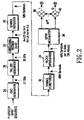
- FIG. 2 is a block diagram illustrating an example of a structure of a forward secondary packet data control channel (F-SPDCCH) transmitter according to an embodiment of the present invention
- FIG. 3 is a block diagram illustrating an example of a structure for transmitting channel signals generated by the transmitters of FIGS. 1 and 2 in a base station according to an embodiment of the present invention
- FIG. 4 is a block diagram illustrating an example of a structure of a forward secondary packet data control channel (F-SPDCCH) receiver according to an embodiment of the present invention
- FIG. 5 is a flow chart illustrating an example of steps for receiving a secondary packet data control channel (SPDCCH) in a mobile station according to an embodiment of the present invention, wherein one SPDCCH is used;
- SPDCCH secondary packet data control channel
- FIGS. 6A and 6B are flow charts illustrating an example of steps for receiving two secondary packet data control channels (SPDCCHs) in a mobile station according to an embodiment of the present invention
- FIG. 7 is a block diagram illustrating an example of a partial structure of an SPDCCH receiver with a Viterbi decoder according to an embodiment of the present invention
- FIG. 8 is a block diagram illustrating an example of a schematic structure of a Viterbi decoder according to an embodiment of the present invention.
- FIG. 9 is a block diagram illustrating an example of a detailed structure of a controller for detecting a data rate according to an embodiment of the present invention.
- FIG. 10 is a flowchart illustrating an example of steps for detecting a data rate according to an embodiment of the present invention.
- the present invention provides herein a receiver structure for efficiently demodulating a packet data control channel (PDCCH) that transmits various control information necessary for the demodulation of a packet data channel (PDCH) in a mobile communication system which is capable of supporting a multimedia service including a voice service and a low-speed circuit and high-speed packet data service, using a 1 ⁇ bandwidth.
- the present invention provides a receiver structure for efficiently receiving a plurality of packet data control channels which are multiplexed by code division multiplexing (CDM).
- CDM code division multiplexing
- forward link refers to a link transmitted from a base station of a known cellular communication system to a mobile station
- reverse link refers to a link transmitted from a mobile station to a base station
- Channels for a forward link packet data service are divided into a common channel, a control channel and a traffic channel.
- the common channel typically represents a pilot channel (PICH), and is used to provide a reference amplitude and a phase variation necessary for synchronous demodulation at a mobile station.
- the traffic channel includes a packet data channel (PDCH) that actually carries forward packet data
- the control channel includes two separated channels that transmit control information related to the packet data channel.
- a first control channel transmits, to a mobile station, subpacket length information indicating the number of slots constituting forward packet data.
- a second control channel transmits, to a mobile station, (i) a medium access control identifier (MAC_ID) as a user identifier indicating a destination mobile station of a forward transmission packet, (ii) a subpacket identifier (SP_ID) indicating whether a transmission packet is a new packet or a retransmitted packet, (iii) an automatic repeat request (ARQ) channel identifier (ARQ_ID) indicating an ARQ channel corresponding to a transmission packet among a plurality of ARQ channels when parallel transmission is used, (iv) an encoder packet (EP) size indicating a size of a transmission packet, and (v) a Walsh space indicator indicating Walsh codes used for a packet data channel.
- the secondary packet data control channel transmits, to a mobile station, (i) a medium access control identifier (MAC_ID) as a user
- F-PDCH forward packet data channel
- each mobile station Since a forward packet data channel (F-PDCH) is simultaneously received at all mobile stations, each mobile station must distinguish a packet uniquely assigned to its user for accurate packet reception. Since user information and control information for a packet transmitted over F-PDCH are separately transmitted over two control channels, packet data transmitted over F-PDCH cannot be restored until demodulation on the two control channels is completed. Actually, however, demodulation on the F-PDCH can be performed after demodulation on the F-SPDCCH out of the two control channels is completed. This is a result of the length information of a packet transmitted over F-PPDCCH can be spontaneously determined by demodulating F-SPDCCH. In an embodiment of the present invention, data received on F-PDCH is temporarily stored until demodulation on F-SPDCCH is completed.
- a mobile station cannot determine (i) whether data received on F-PDCH is data assigned thereto, (ii) a size of a received packet, (iii) a modulation scheme, (iv) whether a received packet is a retransmitted packet, and (v) Walsh code numbers in use, until demodulation on the F-SPDCCH is completed.
- CDM when CDM is used, there may simultaneously exist a plurality of F-SPDCCHs. Actually, even though CDM is used, the maximum number of available SPDCCHs is limited to 2 due to limitations on performance.
- a base station since a base station transmits control information for F-PDCH of each user over as many independent F-SPDCCHs as the number of users, a mobile station must detect only a particular F-SPDCCH including control information indicating transmission of packet data thereto from the F-SPDCCHs, and then demodulate the F-SPDCCH.
- the present invention provides a receiver and reception method for effectively demodulating a forward packet data control channel (F-PDCCH) that transmits control information necessary for demodulation of a packet data channel (PDCH), in a system that uses CDM in order to simultaneously support a packet data service to a plurality of users in addition to time division multiplexing (TDM) fundamentally used in F-PDCH for packet data transmission.
- F-PDCCH forward packet data control channel
- PDCH packet data channel
- CDM time division multiplexing
- FIG. 1 is a block diagram illustrating an example of a structure of a packet data channel (PDCH) transmitter according to an embodiment of the present invention.
- a cyclic redundancy code (CRC) generator 2 generates a CRC for input packet data having a predetermined number of bits, and attaches the generated CRC to the input packet data.
- the CRC has 8 bits.
- a tail bit generator 4 attaches tail bits e.g., 8 zero-bits for convergence during decoding, to the CRC-attached packet data from the CRC generator 2 .
- An encoder 6 encodes a bit stream from the tail bit generator 4 and generates code symbols or coded symbols.
- the encoder 6 represents a turbo encoder that turbo-encodes an input bit stream and generates a predetermined number of code symbols according to a code rate R. For example, if a code rate of 1 ⁇ 5 is used, the encoder 6 generates 5 code symbols X, Y 0 , Y 0 ′, Y 1 and Y 1 ′ for 1 input bit.
- a channel interleaver 8 interleaves the code symbols from the encoder 6 .
- a symbol selector 10 selects (or repeatedly selects) a predetermined number of symbols among the interleaved symbols from the channel interleaver 8 .
- the symbols generated from the symbol selector 10 become a quasi complementary turbo code (QCTC).
- QCTC quasi complementary turbo code
- a symbol demultiplexer (DEMUX) 16 demultiplexes the modulation symbols from the modulator 14 into preferably as many modulation symbols as the number of Walsh codes currently available for a packet data channel (PDCH), and then outputs the demultiplexed modulation symbols over a plurality of I channels and Q channels.
- a plurality of Walsh coverers 18 and 20 each receive symbols on a corresponding I channel and Q channel from the symbol demultiplexer 16 , and spread the received symbols with a corresponding Walsh code among the Walsh codes available for PDCH.
- a Walsh chip level summer 22 chip-level-sums outputs of the Walsh coverers 18 and 20 according to I and Q channels, and generates its outputs over an I channel and a Q channel.
- the I channel and the Q channel of the Walsh chip level summer 22 are applied to terminals A and B of FIG. 3 , respectively.
- the I channel and the Q channel are converted into a radio frequency (RF) band through pseudo-random noise (PN) spreading and baseband filtering, and then transmitted through an antenna.
- RF radio frequency
- PN pseudo-random noise
- FIG. 2 is a block diagram illustrating an example of a structure of a secondary packet data control channel (SPDCCH) transmitter according to an embodiment of the present invention.
- a CRC generator 24 generates a CRC for an input sequence representing control information necessary for demodulation of a packet data channel, and attaches the generated CRC to the input sequence.
- the CRC has 8 bits.
- a tail bit generator 26 attaches 8 tail bits e.g., 8 zero-bits for convergence during decoding, to the CRC-attached input sequence from the CRC generator 24 , and outputs a 29-bit stream.
- a convolutional encoder 28 convolutional-encodes the tail-attached bit stream from the tail bit generator 26 , and generates code symbols.
- a constraint length K of the convolutional encoder 28 is preferably 9.
- a modulator 36 Quadrature Phase Shift Keying (QPSK) modulates the interleaved symbols provided from the interleaver 34 , and generates modulation symbols of I and Q channels.
- Multipliers 38 and 40 each spread the modulation symbols from the modulator 36 with a Walsh code of length 64 , assigned to F-SPDCCH. Outputs of the multipliers 38 and 40 are applied to the terminals A and B of FIG. 3 , respectively. In FIG. 3 , the outputs of the multipliers 38 and 40 are converted into an RF band through PN spreading and baseband filtering, and then transmitted through an antenna.
- QPSK Quadrature Phase Shift Keying
- a channel signal generated from the secondary packet data control channel (F-SPDCCH) transmitter of FIG. 2 is CDM-multiplexed with other channel signals such as a primary packet data control channel (F-PPDCCH) signal, a packet data channel (F-PDCH) signal and a pilot channel (PICH) signal before being transmitted.
- F-PPDCCH primary packet data control channel
- F-PDCH packet data channel
- PICH pilot channel
- control information transmitted over a secondary packet data control channel comprises(i) 6-bit MAC_ID indicating a user scheduled to receive packet data, (ii) 2-bit SP_ID indicating whether a transmission packet is a retransmitted packet, (iii) 2-bit ARQ_ID indicating an ARQ channel of packet data, and (iv) 3-bit EP_SIZE indicating a size of an encoder packet (EP).
- the control information further includes corresponding additional information such as Walsh space indicator and CDM channel indicator.
- a mobile station acquires the above-stated information based on the control information received over the secondary packet data control channel (F-SPDCCH), and uses the acquired information for demodulation of a packet data channel.
- FIG. 3 is a block diagram illustrating an example of a structure for transmitting channel signals generated by the transmitters of FIGS. 1 and 2 in a base station according to an embodiment of the present invention.
- a gain controller 42 multiplies I channel and Q channel signals from, for example, PDCH, PPDCCH and SPDCCH transmitters by a corresponding gain.
- a chip level summer 44 chip-level-sums the gain-controlled complex channel signals according to I and Q channels, and generates an output through an I channel and a Q channel.
- a PN spreader 46 multiplies the I channel and Q channel signals from the chip level summer 44 by PN codes PN_I and PN_Q for the complex channels.
- Baseband filters 48 and 50 each baseband-filters the PN-spread signals received from the PN spreader 46 .
- Multipliers 52 and 54 each convert their corresponding baseband-filtered signals into corresponding carrier bands fc.
- An adder 56 generates a forward modulated waveform by adding outputs of the multipliers 52 and 54 , and then transmits the generated forward modulated waveform to an antenna (not shown).
- FIG. 4 is a block diagram illustrating an example of a structure of a secondary packet data control channel (F-SPDCCH) receiver according to an embodiment of the present invention.
- the receiver of FIG. 4 corresponds to the transmitter of FIG. 2 .
- multipliers 51 and 52 despread received signals preferably with a Walsh code W i 64 assigned to the secondary packet data control channel.
- a QPSK demodulator 53 QPSK-demodulates outputs of the multipliers 51 and 52 , and generates demodulation symbols or demodulated symbols.
- a deinterleaver 54 deinterleaves the demodulation symbols from the QPSK demodulator 53 according to a predetermined deinterleaving rule.
- a symbol inserter 55 inserts zero-symbols into the deinterleaved symbols from the deinterleaver 54 according to a predetermined insertion rule.
- a symbol combiner 56 combines the symbols provided from the symbol inserter 55 according to a predetermined combining rule.
- a decoder 57 under the control of a controller 59 , decodes the symbols of consecutive slots provided from the symbol combiner 56 and generates a bit stream representing control information MAC_ID, SP_ID, ARQ_ID, EP_SIZE, and so on of the secondary packet data control channel.
- the bit stream is divided into information bits and CRC bits.
- a CRC checker 58 performs a CRC check on the information bits generated from the decoder 57 , and provides the CRC check result to the controller 59 .
- the controller 59 controls a decoding period of the decoder 57 , and determines whether a secondary packet data control channel is acquired or not, based on the CRC check result of the CRC checker 58 . If the CRC check passed for example, CRC OK, the controller 59 provides a packet data channel (PDCH) receiver with information bits except the CRC bits so that the PDCH receiver can use the information bits for the demodulation of packet data.
- PDCH packet data channel
- a secondary packet data control channel supports a plurality of data rates. Therefore, the controller 59 must detect a data rate and a slot length, used during transmission of control information, from the data decoded by the decoder 57 .
- a decision method of detecting a data rate from received data is classified into a pre-decision method and a post-decision method.
- the pre-decision method detects a data rate before decoding of a frame, and then performs decoding according to the detected data rate
- the post-decision method detects a data rate after decoding of a frame, and then acquires a decoding result data corresponding to the detected data rate.
- the post-decision method generally performs decoding on all possible data rates, and then determines a data rate based on the decoding results.
- an error check result based on CRC bits included in received data serves as a criterion for determining a data rate.
- the post-decision method preferably performs, in principle, decoding on possible slot lengths of the SPDCCH each time symbols of every slot are received. Performing decoding on all possible slot lengths every slot even though possible slot lengths of the SPDCCH are predetermined is very inefficient and causes an increase in delay before reception of a packet data channel.
- the present invention can detect an accurate slot length by performing decoding as many times as an actually needed number according to decoding results at a previous slot, instead of performing decoding on all possible slot lengths of SPDCCH every slot in order to demodulate SPDCCH.
- an operation of detecting a data rate, or a slot length, of SPDCCH according to the present invention will be described in detail with reference to the accompanying drawings, and for the sake of convenience, an operation of the decoder 57 will first be described. In addition, a description will be separately made of one case where one SPDCCH is used and another case where a plurality of CDM-multiplexed SPDCCHs are used.
- FIG. 5 is a flow chart illustrating an example of steps for receiving a secondary packet data control channel (SPDCCH) in a mobile station according to an embodiment of the present invention, wherein one SPDCCH is used. This procedure is assumed to be performed by the controller 59 of FIG. 4 .
- SPDCCH secondary packet data control channel
- the 1-slot flag, 2-slot flag and 4-slot flag are provided to detect when SPDCCH uses 1, 2 and 4 slots, respectively.
- the 8-slot flag is provided to detect when SPDCCH uses 4 slots and PDCH uses 8 slots.
- the controller 59 receives symbols of one slot over SPDCCH in step 104 , and increases the slot number by ‘1’ in step 106 .
- the above-stated symbols represent the symbols that were previously received and stored in a buffer arranged in a previous stage of the decoder after being subject to Walsh despreading and symbol combining.
- the controller 59 stores a smaller value out of the increased slot number and a slot number ‘4’ as a new slot number in step 108 , and then proceeds to step 110 because the SPDCCH does not use more than 4 slots.
- “success in decoding” means that the CRC check on the decoding result is successful or has passed. If decoding is not successful even after 4 slots are received, the slot number becomes 4 as before, even though symbols of an additional slot are received and decoded. Therefore, in an embodiment of the present invention, decoding is performed on preferably only 4 slots. However, when 5 or more slots are received, decoding is performed on symbols of the last received 4 slots.
- the controller 59 proceeds to steps 116 , 118 , 120 and 122 , and controls (orders) the decoder 57 to perform decoding on symbols of the last received 4, 4, 2 and 1 slots, respectively.
- the 4 decoding operations can be performed either sequentially by a common decoder, or in parallel by 4 separate decoders having the same structure.
- the slot number is ‘3’, it means that symbols of 3 slots have been received after success in decoding, so it is possible to perform decoding on symbols of the last received 1 slot and 2 slots. That is, since SPDCCH does not use 3 slots, decoding is performed in the same way when the slot number is ‘3’ and the slot number is ‘2’.
- step 124 the controller 59 performs a CRC check on 8 slots using an information bit stream obtained by performing decoding in step 116 . If the CRC check passed for example, CRC OK, the controller 59 sets the 8-slot flag to ‘1’ in step 126 , and sets the slot number to ‘ ⁇ 4’ in step 128 , and then returns to step 102 . However, if the CRC check failed, the controller 59 proceeds to step 142 .
- setting the 8-slot flag to ‘1’ means that a subpacket length (SP_LEN) of a packet data channel is determined as 8 slots, since decoding on 4 slots with an initial state ‘0’ is successful.
- SP_LEN subpacket length
- the slot number is set to ‘ ⁇ 4’ in order to disregard 4 F-SPDCCH slots received from now on.
- the controller 59 performs a CRC check on 4 slots using an information bit stream obtained by performing decoding in step 118 . If the CRC check passed, the controller 59 sets the 4-slot flag to ‘1’ in step 132 , and then proceeds to step 142 . Otherwise, if the CRC check failed, the controller 59 proceeds directly to step 142 .
- step 134 the controller 59 performs a CRC check on 2 slots using an information bit stream obtained by performing decoding in step 120 . If the CRC check passed, the controller 59 sets the 2-slot flag is set to ‘1’ in step 136 , and then proceeds to step 142 . If, however, the CRC check failed, the controller 59 proceeds directly to step 142 . Further, in step 138 , the controller 59 performs a CRC check on 1 slot using an information bit stream obtained by performing decoding in step 122 . If the CRC check passed, the controller 59 sets the 1-slot flag to ‘1’ in step 140 , and then proceeds to step 142 . If, however, the CRC check failed, the controller 59 proceeds directly to step 142 .
- step 142 the controller 59 determines whether any one of the slot flags is set to ‘1’. If any one of the slot flags is set to ‘1’, the controller 59 selects in step 144 one accurate decoding result including F-PDCH-related control information from at least one decoding result among the decoding results of the steps 116 , 118 , 120 and 122 .
- the control information includes MAC_ID, ARQ_ID, EP_SIZE, and SP_ID.
- a slot length corresponding to the selected decoding result is detected as a slot length, or a data rate, of the SPDCCH, used by a transmitter.
- the controller 59 selects in step 144 one decoding result corresponding to only one slot flag set to ‘1’ among the slot flags. Actually, however, due to unpredictable distortion or noise of a radio environment, CRC check on two or more slot lengths may pass. In this case, the controller 59 selects one preferable decoding result among the decoding results corresponding to two or more slot flags set to ‘1’, using an auxiliary criterion other than the CRC check result. A more detailed description of the operation performed in step 144 will be made with reference to FIGS. 7 to 10 .
- step 142 If it is determined in step 142 that there is no flag set to ‘1’, the controller 59 returns to step 102 because symbols of one more consecutive slot must be received, since decoding on symbols of F-SPDCCH, received up to the present, is not successful, i.e., acquiring control information has failed.
- FIGS. 6A and 6B are flow charts illustrating an example of steps for receiving two or more secondary packet data control channels (SPDCCHs) in a mobile station according to an embodiment of the present invention.
- FIG. 6A illustrates a procedure for receiving a first secondary packet data control channel (SPDCCH 1 ) out of two secondary packet data control channels SPDCCH 1 and SPDCCH 2 transmitted by a base station by CDM
- FIG. 6B illustrates a procedure for receiving a second secondary packet data control channel (SPDCCH 2 ).
- SPDCCH 1 first secondary packet data control channel
- SPDCCH 1 and SPDCCH 2 transmitted by a base station by CDM
- FIG. 6B illustrates a procedure for receiving a second secondary packet data control channel (SPDCCH 2 ).
- the controller 59 receives symbols of one slot over F-SPDCCH in step 204 , and increases the slot number by ‘1’ in step 206 .
- the controller 59 stores a smaller value out of the increased slot number and a slot number ‘4’ as a new slot number in step 208 , and then proceeds to step 210 . This is because the SPDCCH does not use more than 4 slots.
- the above-stated symbols represent the symbols that were previously received and stored in a buffer arranged in a previous stage of a decoder after being subject to Walsh despreading and symbol combining.
- the 4 decoding operations can be performed either sequentially by a common decoder, or in parallel by 4 separate decoders having the same structure.
- the controller 59 performs a decoding operation (step 216 ) where an initial state ‘0’ is used to detect F-PDCH having an 8-slot length and a decoding operation (step 218 ) where an initial state ‘1’ is used to detect F-PDCH having a 4-slot length.
- step 224 the controller 59 performs CRC a check on 8 slots using an information bit stream obtained by performing decoding in step 216 . If the CRC check passed for example, CRC OK, the controller 59 sets the 8-slot flag to ‘1’ in step 226 , and sets the slot number to ‘ ⁇ 4’ in step 228 , and then returns to step 202 . However, if the CRC check failed, the controller 59 proceeds to step 242 of FIG. 6B .
- setting the 8-slot flag to ‘1’ means that a subpacket length (SP_LEN) of a packet data channel (PDCH) is determined as 8 slots, since decoding on 4 slots with an initial state ‘0’ is successful.
- SP_LEN subpacket length
- PDCH packet data channel
- the slot number is set to ‘ ⁇ 4’ in order to disregard 4 F-SPDCCH slots received from now on.
- the controller 59 performs a CRC check on 4 slots using an information bit stream obtained by performing decoding in step 218 . If the CRC check passed, the controller 59 sets the 4-slot flag to ‘1’ in step 232 , and then proceeds to step 242 . Otherwise, if the CRC check failed, the controller 59 directly proceeds to step 242 .
- step 234 the controller 59 performs a CRC check on 2 slots using an information bit stream obtained by performing decoding in step 220 . If the CRC check passed, the controller 59 sets the 2-slot flag to ‘1’ in step 236 , and then proceeds to step 242 . If, however, the CRC check failed, the controller directly proceeds to step 242 . Further, in step 238 , the controller performs CRC check on 1 slot using an information bit stream obtained by performing decoding in step 222 . If the CRC check passed, the controller sets the 1-slot flag to ‘1’ in step 240 , and then proceeds to step 242 . If, however, the CRC check failed, the controller 59 directly proceeds to step 242 .
- the controller 59 determines in step 242 whether any one of the slot flags is set to ‘1’. If any one of the slot flags is set to ‘1’, the controller 59 selects in step 244 one accurate decoding result including F-PDCH-related control information from at least one decoding result among the decoding results of the steps 216 , 218 , 220 and 222 .
- the control information includes MAC_ID 1 , ARQ_ID 1 , EP_SIZE 1 , and SP_ID 1 .
- a slot length corresponding to the selected decoding result is detected as a slot length, or a data rate, used by a transmitter for transmission of F-SPDCCH.
- the controller 59 selects one preferable decoding result, using an auxiliary metric other than the CRC check result, and its detailed description will be made later.
- the controller 59 compares MAC_ID 1 , user identification information of F-SPDCCH 1 , included in control information obtained from the selected decoding result with its own MAC_ID assigned from a base station. If the two MAC_IDs are identical to each other, the controller 59 controls in step 250 an F-PDCH receiver to demodulate a corresponding packet data channel F-PDCH 1 using the control information.
- the F-PDCH 1 refers to PDCH indicated by control information of F-SPDCCH 1 .
- step 252 the controller 59 controls in step 252 the F-PDCH receiver to suspend processing on F-PDCH 1 , and then proceeds to step 254 .
- step 254 the controller 59 starts processing on F-SPDCCH 2 according to a subpacket length (SP_LEN) of F-PDCH, acquired from the F-SPDCCH 1 .
- SP_LEN subpacket length
- the controller 59 determines a subpacket length SP_LEN 2 of PDCH 2 , indicated by F-SPDCCH 2 , according to a subpacket length SP_LEN 1 of PDCH 1 , acquired by demodulating F-SPDCCH 1 . If the subpacket length SP_LEN 1 acquired from F-SPDCCH 1 is 8 slots, the controller 59 controls in step 256 the decoder to decode symbols of 4 slots of F-SPDCCH 2 by setting the initial state to ‘0’, and an input to the decoder becomes symbols of the last 4 slots of F-SPDCCH 2 received together with F-SPDCCH 1 .
- the controller 59 controls in step 258 the decoder to decode symbols of 4 slots of F-SPDCCH 2 by setting the initial state to ‘1’, and likewise, an input to the decoder becomes symbols of the last 4 slots of F-SPDCCH 2 received together with F-SPDCCH 1 .
- the controller 59 controls in step 260 the decoder to decode symbols of 2 slots of F-SPDCCH 2 , and an input to the decoder becomes symbols of the last 2 slots of F-SPDCCH 2 received together with F-SPDCCH 1 .
- the controller 59 controls in step 262 the decoder to decode symbols of 1 slots of F-SPDCCH 2 , and an input to the decoder becomes symbols of the last 1 slot of F-SPDCCH 2 received together with F-SPDCCH 1 .
- step 264 the controller 59 performs CRC check on one of the decoding results obtained in steps 256 to 262 . If the CRC check failed, the controller 59 controls in step 268 an F-PDCH receiver to suspend processing on F-PDCH 2 corresponding to F-SPDCCH 2 , and then returns to step 202 in order to continuously perform decoding on F-SPDCCH. Otherwise, if the CRC check passed, the controller 59 extracts, in step 266 , control information necessary for demodulating a corresponding packet data channel F-PDCH 2 , from the decoding result of F-SPDCCH 2 . The control information includes MAC_ID 2 , ARQ_ID 2 , EP_SIZE 2 , and SP_ID 2 . Further, a slot length, or data rate, of F-SPDCCH 2 is determined to be identical to the data rate of F-SPDCCH 1 .
- step 270 the controller 59 compares MAC_ID 2 included in the control information with its own MAC_ID assigned from a base station. If the two MAC_IDs are identical to each other, the controller 59 controls in step 272 an F-PDCH receiver to perform processing on F-PDCH 2 according to the control information. If, however, the two MAC_IDs are different from each other, the controller 59 controls in step 268 the F-PDCH receiver to suspend processing on F-PDCH 2 , and then returns to step 202 .
- the F-SPDCCH 1 , F-SPDCCH 2 , F-PDCH 1 and F-PDCH 2 are simultaneously received, and in order to process first and second F-PDCHs according to the decoding results on first and second F-SPDCCHs, it is necessary to buffer the first and second F-PDCHs while processing the first and second F-SPDCCHs.
- a symbol error rate is typically used as the auxiliary metric.
- the symbol error rate means a difference in the number of symbols based on the result obtained by re-encoding decoded data of a received frame and then comparing the re-encoded data with an original received frame by the symbol. If CRC check on a plurality of candidate rates passed, a receiver compares symbol error rates of the CRC check-passed data rates to detect a data rate having the least symbol error rate.
- the Viterbi decoder performs, on convolutionally-encoded symbols, a Viterbi decoding algorithm comprises branch metric calculation, path selection on a trellis, and trace-back.
- This algorithm outputs a difference between path metric values together with decoded data, each time input symbols are decoded. It can be determined that as the path metric difference becomes larger, decoding is performed more accurately. Therefore, the path metric difference can be used as a decoding reliability criterion.
- a difference between path metrics input to each state (or node) on a trellis is referred to as “frame quality metric (FQM)”, and an accurate slot length of SPDCCH is detected using the FQM.
- FQM frame quality metric
- FIG. 7 is a block diagram illustrating an example of a partial structure of an SPDCCH receiver with a Viterbi decoder according to an embodiment of the present invention.
- a Viterbi decoder 60 , a CRC checker 70 , and a controller 80 for controlling these elements are selectively illustrated in FIG. 7 , and the other elements of the SPDCCH receiver are illustrated in FIG. 4 .
- the controller 80 collects information bit streams, frame quality metrics FQMn and CRC check results CRCn, decoded for each of all possible slot lengths, and detects a slot length of an information bit stream having the largest frame quality metric among good-CRC (or CRC check-passed) information bit streams.
- the Viterbi decoder 60 includes symbol converter 61 , a branch metric generator 62 , a path metric calculator 63 , a path metric memory 64 , a path memory 65 , and a trace-back unit 66 .
- the Viterbi decoder 60 of FIG. 8 performs decoding in such a way that it searches (detects) a code sequence most similar to an input code sequence from all possible code sequences on a particular code.
- the symbol converter 61 arranged in front of the branch metric generator 62 , converts input symbols in the form of 2's complement into a soft decision value in the form of signed-magnitude, for decoding.
- the branch metric generator 62 generates branch metric values for all possible branches at a current state for the symbols in the form of the received soft decision value, and the path metric calculator 63 calculates path metric values for a surviving path toward a particular state based on the branch metric values, and stores the calculated path metric values in the path metric memory 64 .
- an optimal surviving path having the minimum path metric value determined by comparing path metric values stored for two or more states is selected by the path metric calculator 63 , and the history of the selected surviving path is stored in the path memory 65 .
- the trace-back unit 66 determines a decoded information bit stream by tracing-back the surviving path stored in the path memory 65 .
- the Viterbi decoder selects a path input to a corresponding state by comparing path metric values for received paths, at each state on a trellis expressed by paths extending from a particular state to the next state, and if a difference of path metric values between a selected surviving path and a non-selected competitor path is large, it could be said that path selection reliability is high at the state. Therefore, if a difference of path metric values between paths input to each state on the trellis is defined as a state quality metric of the state, the difference value can be used as a reliability criterion of a path input to the state. That is, it can be determined that as the state quality metric is larger, reliability of a path input to the state is higher in the Viterbi decoding process.
- a path metric difference value exceeds a predetermined threshold value at a particular state, a value of a bit assigned to the state is set to ‘1’, and if the path metric difference value does not exceed the threshold value, the value of the bit assigned to the state is set to ‘0’.
- an output bit is ‘1’, it is determined that quality of the decoding result is good, and if the output bit is ‘0’, it is determined that quality of the decoding result is bad.
- a path metric difference value itself instead of a hard decision value determined by comparing the path metric difference value at the final state with a predetermined threshold value. Therefore, as a result of CRC check by the CRC checker 70 of FIG. 7 , if CRC checks on a plurality of slot lengths are passed, the controller 80 compares path metric difference values, or frame quality metrics, obtained through decoding on each of the CRC check-passed slot lengths, and detects one slot length having the largest frame quality metric. As mentioned before, a slot length is related to a data rate. Therefore, a CRC check-passed slot length will be referred to herein as “candidate rate.”
- Frame quality metrics for different data rates cannot be directly compared with each other because a code rate and an input frame length have different values according to the data rate. Therefore, the controller 80 multiplies frame quality metrics for the candidate rates by proper normalization factors (NFs), for normalization, and then compares the results with one another. That is, the controller 80 compares the normalized frame quality metrics with one another, and then detects a data rate having the maximum normalized frame quality metric.
- NFs normalization factors
- the normalization factors are determined by an input frame length of a decoder according to a code rate.
- An increase in a code rate causes an increase in a range of a branch metric value accumulated at every state to form a path metric value. Since the path metric value is also accumulated in a calculation process on the trellis, an increase in length of a frame results in an increase in a frame quality metric.
- the frame length is determined by considering repetition and puncturing during the encoding process.
- FQM_NFi denotes a normalization factor for a data rate i
- Ci denotes code rates of the decoder for the data rate i
- Li denotes an input frame length for the data rate i
- Ln denotes a maximum frame length.
- SPDCCH secondary packet data control channel
- an encoder when 37 bits including tail bits and CRC bits are received, an encoder outputs 48, 96 or 192 bits through repetition and puncturing according to the data rates.
- Li/Ln 37/37.
- calculation results of Equation (1) for the data rates are (37/48)*(37/37), (37/96)*(37/37), (37/192)*(37/37), respectively.
- the normalization factors are determined as 1, 1 ⁇ 2 and 1 ⁇ 4.
- FIG. 9 is a block diagram illustrating an example of a of the controller 80 for detecting a data rate according to an embodiment of the present invention.
- the Viterbi decoder 60 decodes the input frame at a code rate corresponding to the data rate n, and provides the decoded data to the CRC checker 70 and a frame quality metric FQMn generated through the decoding to the controller 80 .
- the CRC checker 70 provides CRC check result CRCn to the controller 80 by consulting CRC bits extracted from the decoded data.
- a candidate rate selector 81 in the controller 80 receives the FQMn and the CRCn and determines whether the CRCn is good. If the CRCn is good, the candidate rate selector 81 provides the frame quality metric FQMn to a multiplier 82 .
- the multiplier 82 multiplies the FQMn by a corresponding normalization factor FQM_NFn, and provides a normalized-frame quality metric FQMn*FQM_NFn to a comparator 83 .
- the normalization factor is calculated in the above-stated method.
- the comparator 83 compares the FQMn*FQM_NFn with a frame quality metric FQM(n ⁇ 1)*FQM_NF(n ⁇ 1) normalized for a previous candidate rate, and stores the larger one in its internal register (not shown). If there is no frame quality metric normalized for a previous candidate rate, i.e., if a frame quality metric normalized for a first candidate rate is received, the comparator 83 stores the received frame quality metric in the internal register without performing comparison. After completing the comparison on the normalized frame quality metrics for all candidate rates, the comparator 83 outputs a normalized frame quality metric MaxFQM with a maximum size. A rate detector 84 then detects a data rate corresponding to the MaxFQM.
- FIG. 10 is a flowchart illustrating an example of steps for detecting a data rate according to an embodiment of the present invention. The algorithm is performed by the controller 80 of FIG. 7 .
- step 310 the controller 80 initializes, to ‘0’, all internal parameters for performing the data rate detection algorithm, including i for identifying data rates, R indicating an index of a detected data rate, and MaxFQM indicating a frame quality metric currently having the maximum size.
- the controller 80 increases the current data rate index i by 1 in step 320 , and determines in step 330 whether the current data rate index i is identical to the number n of data rates. If the current data rate index i is not identical to the number n of data rates, the controller 80 proceeds to step 340 .
- step 340 the controller 80 determines whether CRC check result CRCi for the current data rate index i is good (CRC OK). If the CRCi is good, the controller 80 proceeds to step 350 , and otherwise, returns to step 320 .
- step 350 the controller 80 compares a normalized frame quality metric FQMi*FQM_NFi of a corresponding candidate rate with the MaxFQM. The normalized frame quality metric is generated by multiplying FQM_NFi by a normalization factor corresponding to the FQMi. If the FQMi*FQM_NFi is larger than MaxFQM, the controller 80 proceeds to step 360 . Otherwise, the controller 80 returns to step 320 and determines a next data rate.
- step 360 the controller 80 sets the detected data rate index R to the current data rate index i, and updates the MaxFQM into FQMi*FQM_NFi corresponding to the current data rate index i. After step 360 , the controller 80 returns to step 320 and determines the next data rate.
- step 330 If it is determined in step 330 that the current data rate index i is identical to the number n of data rates, the controller 80 proceeds to step 370 , determining that detection for all data rates has been completed.
- step 370 the controller 80 determines whether the detected data rate index R is equal to ‘0’, to determine whether there exists a detected data rate. If the detected data rate index R is equal to ‘0’, the controller 80 performs a detection fail process in step 390 , determining that there is no detected data rate. Otherwise, the controller 80 detects a data rate corresponding to the detected data rate index R in step 380 .
- the present invention can reduce a demodulation time and power consumption of a packet data control channel by providing an efficient demodulation algorithm for the dedicated packet data control channel. Also, when CDM is used to simultaneously support a packet data service to a plurality of users, the present invention can reduce a demodulation time and power consumption of a packet data control channel by providing an algorithm for efficiently demodulating the packet data control channel.
- the proposed demodulation algorithm for a packet data control channel is used, time delay from a reception time of a packet data channel to a demodulation time of the packet data channel can be reduced, thus contributing to rapid demodulation of the packet data channel.
- the present invention detects the data rate based on a frame quality metric output from a Viterbi decoder.
- the rate detection is accomplished along with decoding on a received data frame, preventing a waste of time due to additional calculations and an increase in calculations compared with the existing Viterbi decoder. Therefore, the proposed rate detection method can be effectively applied to a secondary packet data control channel (SPDCCH) defined by IS-2000 1 ⁇ EVDV standard that requires high-speed processing.
- SPDCCH secondary packet data control channel
Abstract
Description
FQM — NFi=Ci*Li/Ln (1)
Claims (43)
FQM — NFi=Ci*Li/Ln
FQM — NFi=Ci*Li/Ln
Applications Claiming Priority (4)
| Application Number | Priority Date | Filing Date | Title |
|---|---|---|---|
| KR20020016858 | 2002-03-27 | ||
| KR2002-16858 | 2002-03-27 | ||
| KR20020061590 | 2002-10-09 | ||
| KR2002-61590 | 2002-10-09 |
Publications (2)
| Publication Number | Publication Date |
|---|---|
| US20030188252A1 US20030188252A1 (en) | 2003-10-02 |
| US7487430B2 true US7487430B2 (en) | 2009-02-03 |
Family
ID=27807071
Family Applications (1)
| Application Number | Title | Priority Date | Filing Date |
|---|---|---|---|
| US10/397,522 Active 2025-10-24 US7487430B2 (en) | 2002-03-27 | 2003-03-27 | Apparatus and method for receiving packet data control channel in a mobile communication system |
Country Status (6)
| Country | Link |
|---|---|
| US (1) | US7487430B2 (en) |
| EP (1) | EP1349313B1 (en) |
| KR (1) | KR100547822B1 (en) |
| CN (1) | CN100568848C (en) |
| AU (1) | AU2003214677B2 (en) |
| WO (1) | WO2003081854A1 (en) |
Cited By (11)
| Publication number | Priority date | Publication date | Assignee | Title |
|---|---|---|---|---|
| US20060050813A1 (en) * | 2004-08-20 | 2006-03-09 | Arie Heiman | Method and system for decoding video, voice, and speech data using redundancy |
| US20080209302A1 (en) * | 2007-01-30 | 2008-08-28 | Via Telecom Inc. | System and method for f-scch and r-odcch performance improvement |
| US20090022079A1 (en) * | 2005-05-04 | 2009-01-22 | Fei Frank Zhou | Method and apparatus for providing enhanced channel interleaving |
| US20090196382A1 (en) * | 2006-08-28 | 2009-08-06 | Sony Deutschland Gmbh | Equalizing structure and equalizing method |
| US20100091826A1 (en) * | 2008-10-14 | 2010-04-15 | Ning Chen | Techniques for Improving Channel Estimation and Tracking in a Wireless Communication System |
| US20110225479A1 (en) * | 2010-03-11 | 2011-09-15 | Microsoft Corporation | Fast and reliable wireless communication |
| US20120210197A1 (en) * | 2011-02-15 | 2012-08-16 | Samsung Electronics Co. Ltd. | Apparatus and method for decoding in communication system |
| US20130194955A1 (en) * | 2006-11-30 | 2013-08-01 | Broadcom Corporation | Method and System for UMTS HSDPA Shared Control Channel Processing |
| US8924830B2 (en) | 2004-08-20 | 2014-12-30 | Broadcom Corporation | Method and system for decoding control data in GSM-based systems using inherent redundancy |
| US9300324B2 (en) | 2004-09-25 | 2016-03-29 | Tq Delta, Llc | CRC counter normalization |
| US11489625B2 (en) * | 2017-05-06 | 2022-11-01 | Qualcomm Incorporated | Rate-matching scheme for polar codes |
Families Citing this family (40)
| Publication number | Priority date | Publication date | Assignee | Title |
|---|---|---|---|---|
| IL155221A0 (en) * | 2003-04-03 | 2003-11-23 | Wavextend Ltd | Phased array antenna for indoor application |
| FR2853976B1 (en) * | 2003-04-16 | 2005-06-03 | Canon Kk | CODING OF INFORMATION BY CODE OF ALGEBRA GEOMETRY PROVIDING TWO DECODING OPTIONS |
| KR101002814B1 (en) * | 2003-10-02 | 2010-12-21 | 삼성전자주식회사 | Method and apparatus for receiving forward packet data control channel in a mobile communication system supporting packet data service |
| US20070183385A1 (en) * | 2003-10-10 | 2007-08-09 | Hao Bi | Apparatus and method for distinguishing a frame on channel shared by multiple users |
| US7859985B2 (en) * | 2004-03-22 | 2010-12-28 | Texas Instruments Incorporated | Control on at least one frequency selecting data carrier frequencies |
| US7792134B2 (en) * | 2004-04-30 | 2010-09-07 | Alcatel-Lucent Usa Inc. | Method and apparatus for detecting an uplink packet data channel in a CDMA wireless communications system |
| KR101412174B1 (en) * | 2007-10-17 | 2014-06-26 | 삼성전자주식회사 | Method and apparatus for decoding in portable communication system |
| EP2109244A1 (en) * | 2008-04-09 | 2009-10-14 | Siemens Aktiengesellschaft | Method for security-oriented transmission, security switch device and control unit |
| JP4661938B2 (en) * | 2008-10-28 | 2011-03-30 | ソニー株式会社 | Wireless communication apparatus, wireless communication method, and computer program |
| US20110182385A1 (en) * | 2009-07-30 | 2011-07-28 | Qualcomm Incorporated | Method and apparatus for reliability-aided pruning of blind decoding results |
| US20130039266A1 (en) | 2011-08-08 | 2013-02-14 | Research In Motion Limited | System and method to increase link adaptation performance with multi-level feedback |
| US10210559B2 (en) | 2012-05-17 | 2019-02-19 | Walmart Apollo, Llc | Systems and methods for recommendation scraping |
| US20130311260A1 (en) | 2012-05-17 | 2013-11-21 | Luvocracy Inc. | Reward Structures |
| US10181147B2 (en) | 2012-05-17 | 2019-01-15 | Walmart Apollo, Llc | Methods and systems for arranging a webpage and purchasing products via a subscription mechanism |
| US10580056B2 (en) | 2012-05-17 | 2020-03-03 | Walmart Apollo, Llc | System and method for providing a gift exchange |
| US10346895B2 (en) | 2012-05-17 | 2019-07-09 | Walmart Apollo, Llc | Initiation of purchase transaction in response to a reply to a recommendation |
| US8930800B2 (en) * | 2012-08-14 | 2015-01-06 | GM Global Technology Operations LLC | Method and apparatus of triple-decoding for IEEE 802.11p physical layer mechanism |
| US8751915B2 (en) * | 2012-08-28 | 2014-06-10 | Lsi Corporation | Systems and methods for selectable positive feedback data processing |
| US9118480B2 (en) | 2013-02-11 | 2015-08-25 | Telefonaktiebolaget Lm Ericsson (Publ) | Frame quality estimation during viterbi decoding |
| US9214959B2 (en) | 2013-02-19 | 2015-12-15 | Avago Technologies General Ip (Singapore) Pte. Ltd. | Systems and methods for skip layer data decoding |
| US9274889B2 (en) | 2013-05-29 | 2016-03-01 | Avago Technologies General Ip (Singapore) Pte. Ltd. | Systems and methods for data processing using global iteration result reuse |
| US8959414B2 (en) | 2013-06-13 | 2015-02-17 | Lsi Corporation | Systems and methods for hybrid layer data decoding |
| US9391903B2 (en) * | 2013-07-15 | 2016-07-12 | Calix, Inc. | Methods and apparatuses for distributed packet flow control |
| US9680760B2 (en) * | 2013-07-16 | 2017-06-13 | Cisco Technology, Inc. | Adaptive marking for WRED with intra-flow packet priorities in network queues |
| US8917466B1 (en) | 2013-07-17 | 2014-12-23 | Lsi Corporation | Systems and methods for governing in-flight data sets in a data processing system |
| US8817404B1 (en) | 2013-07-18 | 2014-08-26 | Lsi Corporation | Systems and methods for data processing control |
| US9319293B2 (en) | 2013-07-31 | 2016-04-19 | Calix, Inc. | Methods and apparatuses for network flow analysis and control |
| US9196299B2 (en) | 2013-08-23 | 2015-11-24 | Avago Technologies General Ip (Singapore) Pte. Ltd. | Systems and methods for enhanced data encoding and decoding |
| US8908307B1 (en) | 2013-08-23 | 2014-12-09 | Lsi Corporation | Systems and methods for hard disk drive region based data encoding |
| US9298720B2 (en) | 2013-09-17 | 2016-03-29 | Avago Technologies General Ip (Singapore) Pte. Ltd. | Systems and methods for fragmented data recovery |
| US9240938B2 (en) | 2013-09-23 | 2016-01-19 | Calix, Inc. | Distributed system and method for flow identification in an access network |
| US9219503B2 (en) | 2013-10-16 | 2015-12-22 | Avago Technologies General Ip (Singapore) Pte. Ltd. | Systems and methods for multi-algorithm concatenation encoding and decoding |
| US9323606B2 (en) | 2013-11-21 | 2016-04-26 | Avago Technologies General Ip (Singapore) Pte. Ltd. | Systems and methods for FAID follower decoding |
| US9363750B2 (en) * | 2013-12-06 | 2016-06-07 | Qualcomm Incorporated | Devices and methods for control channel decoding with preamble skip to reduce decoding time |
| RU2014104571A (en) | 2014-02-10 | 2015-08-20 | ЭлЭсАй Корпорейшн | SYSTEMS AND METHODS FOR AN EFFECTIVE PERFORMANCE AREA FOR DATA ENCODING |
| US9378765B2 (en) | 2014-04-03 | 2016-06-28 | Seagate Technology Llc | Systems and methods for differential message scaling in a decoding process |
| KR102372362B1 (en) | 2015-09-22 | 2022-03-08 | 삼성전자주식회사 | Digital signal processor using signed magnitude and wireless comunication receiver having the same |
| US9686783B1 (en) * | 2015-11-11 | 2017-06-20 | Mbit Wireless, Inc. | Method and apparatus for PDCCH detection |
| US11316633B2 (en) * | 2018-02-08 | 2022-04-26 | Qualcomm Incorporated | Bandwidth-dependent positioning reference signal (PRS) transmission for narrowband internet of things (NB-IoT) observed time difference of arrival (OTDOA) positioning |
| CN110768747B (en) * | 2018-07-27 | 2022-05-10 | 瑞昱半导体股份有限公司 | Convolutional code decoder and convolutional code decoding method |
Citations (16)
| Publication number | Priority date | Publication date | Assignee | Title |
|---|---|---|---|---|
| EP0763902A1 (en) | 1995-09-15 | 1997-03-19 | Nokia Mobile Phones Ltd. | Methods and apparatus for performing rate determination based on the growth of a path metric in a Viterbi decoder |
| WO1999014885A2 (en) | 1997-09-18 | 1999-03-25 | Nokia Mobile Phones Limited | Time diversity in a tdma system |
| US5923713A (en) * | 1996-02-28 | 1999-07-13 | Sony Corporation | Viterbi decoder |
| US5982822A (en) * | 1996-02-28 | 1999-11-09 | Sony Corporation | Viterbi decoder |
| US6094465A (en) * | 1997-03-21 | 2000-07-25 | Qualcomm Incorporated | Method and apparatus for performing decoding of CRC outer concatenated codes |
| WO2001024465A1 (en) | 1999-09-30 | 2001-04-05 | Telefonaktiebolaget Lm Ericsson (Publ) | Blind rate detection in a multiplexed transmission system |
| EP1117202A2 (en) | 2000-01-14 | 2001-07-18 | Marconi Communications Limited | Method of communicating data in communication systems |
| WO2001052467A1 (en) | 2000-01-10 | 2001-07-19 | Qualcomm Incorporated | Method and apparatus for supporting adaptive multi-rate (amr) data in a cdma communication system |
| US6356595B1 (en) * | 1997-10-14 | 2002-03-12 | Sony Corporation | Method and apparatus for decoding continuously coded convolutionally encoded messages |
| US20030007476A1 (en) * | 2001-06-27 | 2003-01-09 | Samsung Electronics Co., Ltd. | Apparatus and method for transmitting and receiving data in a CDMA mobile communication system |
| US20030086385A1 (en) * | 2001-11-07 | 2003-05-08 | Samsung Electronics Co., Ltd. | Apparatus for transmitting/receiving data on packet data control channel in a communication system |
| US20030103480A1 (en) * | 2001-12-05 | 2003-06-05 | Lg Electronics Inc. | Error detection code generating method and error detection code generator |
| US6798736B1 (en) * | 1998-09-22 | 2004-09-28 | Qualcomm Incorporated | Method and apparatus for transmitting and receiving variable rate data |
| US6804220B2 (en) * | 2001-05-07 | 2004-10-12 | Qualcomm Incorporated | Method and apparatus for generating control information for packet data |
| US6870890B1 (en) * | 1999-08-31 | 2005-03-22 | Intel Corporation | Power saving in communication terminals |
| US6928065B2 (en) * | 2002-06-11 | 2005-08-09 | Motorola, Inc. | Methods of addressing and signaling a plurality of subscriber units in a single slot |
Family Cites Families (2)
| Publication number | Priority date | Publication date | Assignee | Title |
|---|---|---|---|---|
| CN1194475C (en) * | 1996-06-24 | 2005-03-23 | Ntt移动通信网株式会社 | Data transmitting method, data transmitting system, transmitter and receiver |
| US6941132B2 (en) * | 2000-03-20 | 2005-09-06 | Telefonaktiebolaget L M Ericsson (Publ) | Transport of radio network-originated control information |
-
2003
- 2003-03-27 US US10/397,522 patent/US7487430B2/en active Active
- 2003-03-27 CN CNB038070928A patent/CN100568848C/en not_active Expired - Fee Related
- 2003-03-27 AU AU2003214677A patent/AU2003214677B2/en not_active Ceased
- 2003-03-27 WO PCT/KR2003/000617 patent/WO2003081854A1/en active IP Right Grant
- 2003-03-27 KR KR1020030019196A patent/KR100547822B1/en not_active IP Right Cessation
- 2003-03-27 EP EP03006823A patent/EP1349313B1/en not_active Expired - Fee Related
Patent Citations (18)
| Publication number | Priority date | Publication date | Assignee | Title |
|---|---|---|---|---|
| EP0763902A1 (en) | 1995-09-15 | 1997-03-19 | Nokia Mobile Phones Ltd. | Methods and apparatus for performing rate determination based on the growth of a path metric in a Viterbi decoder |
| US5923713A (en) * | 1996-02-28 | 1999-07-13 | Sony Corporation | Viterbi decoder |
| US5982822A (en) * | 1996-02-28 | 1999-11-09 | Sony Corporation | Viterbi decoder |
| US6094465A (en) * | 1997-03-21 | 2000-07-25 | Qualcomm Incorporated | Method and apparatus for performing decoding of CRC outer concatenated codes |
| WO1999014885A2 (en) | 1997-09-18 | 1999-03-25 | Nokia Mobile Phones Limited | Time diversity in a tdma system |
| US6356595B1 (en) * | 1997-10-14 | 2002-03-12 | Sony Corporation | Method and apparatus for decoding continuously coded convolutionally encoded messages |
| US6798736B1 (en) * | 1998-09-22 | 2004-09-28 | Qualcomm Incorporated | Method and apparatus for transmitting and receiving variable rate data |
| US20040218570A1 (en) * | 1998-09-22 | 2004-11-04 | Black Peter J. | Method and apparatus for transmitting and receiving variable rate data |
| US6870890B1 (en) * | 1999-08-31 | 2005-03-22 | Intel Corporation | Power saving in communication terminals |
| WO2001024465A1 (en) | 1999-09-30 | 2001-04-05 | Telefonaktiebolaget Lm Ericsson (Publ) | Blind rate detection in a multiplexed transmission system |
| WO2001052467A1 (en) | 2000-01-10 | 2001-07-19 | Qualcomm Incorporated | Method and apparatus for supporting adaptive multi-rate (amr) data in a cdma communication system |
| CN1306351A (en) | 2000-01-14 | 2001-08-01 | 马科尼通讯有限公司 | Method of transmitting data in communicating system |
| EP1117202A2 (en) | 2000-01-14 | 2001-07-18 | Marconi Communications Limited | Method of communicating data in communication systems |
| US6804220B2 (en) * | 2001-05-07 | 2004-10-12 | Qualcomm Incorporated | Method and apparatus for generating control information for packet data |
| US20030007476A1 (en) * | 2001-06-27 | 2003-01-09 | Samsung Electronics Co., Ltd. | Apparatus and method for transmitting and receiving data in a CDMA mobile communication system |
| US20030086385A1 (en) * | 2001-11-07 | 2003-05-08 | Samsung Electronics Co., Ltd. | Apparatus for transmitting/receiving data on packet data control channel in a communication system |
| US20030103480A1 (en) * | 2001-12-05 | 2003-06-05 | Lg Electronics Inc. | Error detection code generating method and error detection code generator |
| US6928065B2 (en) * | 2002-06-11 | 2005-08-09 | Motorola, Inc. | Methods of addressing and signaling a plurality of subscriber units in a single slot |
Cited By (25)
| Publication number | Priority date | Publication date | Assignee | Title |
|---|---|---|---|---|
| US8359523B2 (en) | 2004-08-20 | 2013-01-22 | Broadcom Corporation | Method and system for decoding video, voice, and speech data using redundancy |
| US20060050813A1 (en) * | 2004-08-20 | 2006-03-09 | Arie Heiman | Method and system for decoding video, voice, and speech data using redundancy |
| US8924830B2 (en) | 2004-08-20 | 2014-12-30 | Broadcom Corporation | Method and system for decoding control data in GSM-based systems using inherent redundancy |
| US7716565B2 (en) * | 2004-08-20 | 2010-05-11 | Broadcom Corporation | Method and system for decoding video, voice, and speech data using redundancy |
| US20100223537A1 (en) * | 2004-08-20 | 2010-09-02 | Arie Heiman | Method and System for Decoding Video, Voice, and Speech Data Using Redundancy |
| US9300324B2 (en) | 2004-09-25 | 2016-03-29 | Tq Delta, Llc | CRC counter normalization |
| US10346243B2 (en) | 2004-09-25 | 2019-07-09 | Tq Delta, Llc | CRC counter normalization |
| US10049003B2 (en) | 2004-09-25 | 2018-08-14 | Tq Delta, Llc | CRC counter normalization |
| US20090022079A1 (en) * | 2005-05-04 | 2009-01-22 | Fei Frank Zhou | Method and apparatus for providing enhanced channel interleaving |
| US8249196B2 (en) * | 2006-08-28 | 2012-08-21 | Sony Deutschland Gmbh | Equalizing structure and equalizing method |
| US20090196382A1 (en) * | 2006-08-28 | 2009-08-06 | Sony Deutschland Gmbh | Equalizing structure and equalizing method |
| US20130194955A1 (en) * | 2006-11-30 | 2013-08-01 | Broadcom Corporation | Method and System for UMTS HSDPA Shared Control Channel Processing |
| US9066248B2 (en) * | 2006-11-30 | 2015-06-23 | Broadcom Corporation | Method and system for UMTS HSDPA shared control channel processing |
| US20080209302A1 (en) * | 2007-01-30 | 2008-08-28 | Via Telecom Inc. | System and method for f-scch and r-odcch performance improvement |
| US20100091826A1 (en) * | 2008-10-14 | 2010-04-15 | Ning Chen | Techniques for Improving Channel Estimation and Tracking in a Wireless Communication System |
| US9137055B2 (en) | 2008-10-14 | 2015-09-15 | Apple Inc. | Techniques for improving channel estimation and tracking in a wireless communication system |
| US9712309B2 (en) | 2008-10-14 | 2017-07-18 | Apple Inc. | Techniques for improving channel estimation and tracking in a wireless communication system |
| US8238482B2 (en) * | 2008-10-14 | 2012-08-07 | Apple Inc. | Techniques for improving channel estimation and tracking in a wireless communication system |
| US20110225479A1 (en) * | 2010-03-11 | 2011-09-15 | Microsoft Corporation | Fast and reliable wireless communication |
| US8341504B2 (en) * | 2010-03-11 | 2012-12-25 | Microsoft Corporation | Fast and reliable wireless communication |
| US8522117B2 (en) | 2010-03-11 | 2013-08-27 | Microsoft Corporation | Fast and reliable wireless communication |
| US8843811B2 (en) * | 2011-02-15 | 2014-09-23 | Samsung Electronics Co., Ltd. | Apparatus and method for decoding in communication system |
| US20120210197A1 (en) * | 2011-02-15 | 2012-08-16 | Samsung Electronics Co. Ltd. | Apparatus and method for decoding in communication system |
| US11489625B2 (en) * | 2017-05-06 | 2022-11-01 | Qualcomm Incorporated | Rate-matching scheme for polar codes |
| US11956079B2 (en) | 2017-05-06 | 2024-04-09 | Qualcomm Incorporated | Rate-matching scheme for polar codes |
Also Published As
| Publication number | Publication date |
|---|---|
| KR20030078033A (en) | 2003-10-04 |
| US20030188252A1 (en) | 2003-10-02 |
| CN100568848C (en) | 2009-12-09 |
| EP1349313B1 (en) | 2012-04-18 |
| WO2003081854A1 (en) | 2003-10-02 |
| CN1643859A (en) | 2005-07-20 |
| AU2003214677B2 (en) | 2005-12-22 |
| EP1349313A1 (en) | 2003-10-01 |
| AU2003214677A1 (en) | 2003-10-08 |
| KR100547822B1 (en) | 2006-01-31 |
Similar Documents
| Publication | Publication Date | Title |
|---|---|---|
| US7487430B2 (en) | Apparatus and method for receiving packet data control channel in a mobile communication system | |
| US6535496B1 (en) | Receiver method and apparatus with complex pilot filter | |
| EP0993740B1 (en) | A subscriber unit and method for use in a wireless communication system | |
| EP0903023B1 (en) | Transmission of signaling data in an adjustable rate wireless communication system | |
| US5926500A (en) | Reduced peak-to-average transmit power high data rate CDMA wireless communication system | |
| US6768728B1 (en) | Device and method for exchanging frame messages of different lengths in CDMA communication system | |
| US5822359A (en) | Coherent random access channel in a spread-spectrum communication system and method | |
| US6621875B2 (en) | High data rate CDMA wireless communication system using variable sized channel codes | |
| US7912028B2 (en) | Reducing false detection in an HSDPA 3G terminal | |
| US7751371B2 (en) | Method and apparatus for providing variable rate data in a communications system using non-orthogonal overflow channels | |
| US6233271B1 (en) | Method and apparatus for decoding trellis coded direct sequence spread spectrum communication signals | |
| EP1596519A2 (en) | A subsriber unit and method for use in a wireless communication system | |
| US6917629B1 (en) | Rate detection in radio communication systems | |
| US7324578B2 (en) | Method and apparatus for transmitting and receiving information about spreading codes used for a packet data channel in a communication system | |
| US20080205349A1 (en) | Apparatus and method for encoding and decoding control information in a mobile communication system supporting high-speed packet data transmission | |
| US20100118707A1 (en) | Device and method for determining high speed shared control channel in a communication terminal | |
| WO1997005717A1 (en) | Apparatus and method for rate determination in on-off variable-rate communication systems | |
| KR100790124B1 (en) | A receiver for transmitting packet data effectively in mobile communications system supporting packet data services and method thereof | |
| KR100469708B1 (en) | Apparatus and method for demodulating an f-pdcch and an f-pdch in a mobile station of a mobile communication system | |
| Ghosh et al. | Air-interface for 1XTREME/1xEV-DV | |
| US7130339B2 (en) | Method and apparatus for frame rate determination without decoding in a spread spectrum receiver |
Legal Events
| Date | Code | Title | Description |
|---|---|---|---|
| AS | Assignment |
Owner name: SAMSUNG ELECTONICS CO., LTD., KOREA, REPUBLIC OF Free format text: ASSIGNMENT OF ASSIGNORS INTEREST;ASSIGNORS:KIM, SE-HYOUNG;HONG, WOO-SANG;HA, JI-WON;AND OTHERS;REEL/FRAME:013916/0390 Effective date: 20030325 |
|
| FEPP | Fee payment procedure |
Free format text: PAYOR NUMBER ASSIGNED (ORIGINAL EVENT CODE: ASPN); ENTITY STATUS OF PATENT OWNER: LARGE ENTITY |
|
| STCF | Information on status: patent grant |
Free format text: PATENTED CASE |
|
| FEPP | Fee payment procedure |
Free format text: PAYER NUMBER DE-ASSIGNED (ORIGINAL EVENT CODE: RMPN); ENTITY STATUS OF PATENT OWNER: LARGE ENTITY Free format text: PAYOR NUMBER ASSIGNED (ORIGINAL EVENT CODE: ASPN); ENTITY STATUS OF PATENT OWNER: LARGE ENTITY |
|
| FPAY | Fee payment |
Year of fee payment: 4 |
|
| FPAY | Fee payment |
Year of fee payment: 8 |
|
| MAFP | Maintenance fee payment |
Free format text: PAYMENT OF MAINTENANCE FEE, 12TH YEAR, LARGE ENTITY (ORIGINAL EVENT CODE: M1553); ENTITY STATUS OF PATENT OWNER: LARGE ENTITY Year of fee payment: 12 |