US7482690B1 - Electronic components such as thin array plastic packages and process for fabricating same - Google Patents
Electronic components such as thin array plastic packages and process for fabricating same Download PDFInfo
- Publication number
- US7482690B1 US7482690B1 US11/071,737 US7173705A US7482690B1 US 7482690 B1 US7482690 B1 US 7482690B1 US 7173705 A US7173705 A US 7173705A US 7482690 B1 US7482690 B1 US 7482690B1
- Authority
- US
- United States
- Prior art keywords
- components
- integrated circuit
- die attach
- circuit package
- pads
- Prior art date
- Legal status (The legal status is an assumption and is not a legal conclusion. Google has not performed a legal analysis and makes no representation as to the accuracy of the status listed.)
- Expired - Lifetime, expires
Links
Images


Classifications
-
- H—ELECTRICITY
- H01—ELECTRIC ELEMENTS
- H01L—SEMICONDUCTOR DEVICES NOT COVERED BY CLASS H10
- H01L21/00—Processes or apparatus adapted for the manufacture or treatment of semiconductor or solid state devices or of parts thereof
- H01L21/02—Manufacture or treatment of semiconductor devices or of parts thereof
- H01L21/04—Manufacture or treatment of semiconductor devices or of parts thereof the devices having at least one potential-jump barrier or surface barrier, e.g. PN junction, depletion layer or carrier concentration layer
- H01L21/50—Assembly of semiconductor devices using processes or apparatus not provided for in a single one of the subgroups H01L21/06 - H01L21/326, e.g. sealing of a cap to a base of a container
- H01L21/56—Encapsulations, e.g. encapsulation layers, coatings
- H01L21/568—Temporary substrate used as encapsulation process aid
-
- H—ELECTRICITY
- H01—ELECTRIC ELEMENTS
- H01L—SEMICONDUCTOR DEVICES NOT COVERED BY CLASS H10
- H01L21/00—Processes or apparatus adapted for the manufacture or treatment of semiconductor or solid state devices or of parts thereof
- H01L21/02—Manufacture or treatment of semiconductor devices or of parts thereof
- H01L21/04—Manufacture or treatment of semiconductor devices or of parts thereof the devices having at least one potential-jump barrier or surface barrier, e.g. PN junction, depletion layer or carrier concentration layer
- H01L21/48—Manufacture or treatment of parts, e.g. containers, prior to assembly of the devices, using processes not provided for in a single one of the subgroups H01L21/06 - H01L21/326
- H01L21/4814—Conductive parts
- H01L21/4821—Flat leads, e.g. lead frames with or without insulating supports
- H01L21/4828—Etching
- H01L21/4832—Etching a temporary substrate after encapsulation process to form leads
-
- H—ELECTRICITY
- H01—ELECTRIC ELEMENTS
- H01L—SEMICONDUCTOR DEVICES NOT COVERED BY CLASS H10
- H01L21/00—Processes or apparatus adapted for the manufacture or treatment of semiconductor or solid state devices or of parts thereof
- H01L21/02—Manufacture or treatment of semiconductor devices or of parts thereof
- H01L21/04—Manufacture or treatment of semiconductor devices or of parts thereof the devices having at least one potential-jump barrier or surface barrier, e.g. PN junction, depletion layer or carrier concentration layer
- H01L21/50—Assembly of semiconductor devices using processes or apparatus not provided for in a single one of the subgroups H01L21/06 - H01L21/326, e.g. sealing of a cap to a base of a container
- H01L21/56—Encapsulations, e.g. encapsulation layers, coatings
- H01L21/561—Batch processing
-
- H—ELECTRICITY
- H01—ELECTRIC ELEMENTS
- H01L—SEMICONDUCTOR DEVICES NOT COVERED BY CLASS H10
- H01L21/00—Processes or apparatus adapted for the manufacture or treatment of semiconductor or solid state devices or of parts thereof
- H01L21/67—Apparatus specially adapted for handling semiconductor or electric solid state devices during manufacture or treatment thereof; Apparatus specially adapted for handling wafers during manufacture or treatment of semiconductor or electric solid state devices or components ; Apparatus not specifically provided for elsewhere
- H01L21/683—Apparatus specially adapted for handling semiconductor or electric solid state devices during manufacture or treatment thereof; Apparatus specially adapted for handling wafers during manufacture or treatment of semiconductor or electric solid state devices or components ; Apparatus not specifically provided for elsewhere for supporting or gripping
- H01L21/6835—Apparatus specially adapted for handling semiconductor or electric solid state devices during manufacture or treatment thereof; Apparatus specially adapted for handling wafers during manufacture or treatment of semiconductor or electric solid state devices or components ; Apparatus not specifically provided for elsewhere for supporting or gripping using temporarily an auxiliary support
-
- H—ELECTRICITY
- H01—ELECTRIC ELEMENTS
- H01L—SEMICONDUCTOR DEVICES NOT COVERED BY CLASS H10
- H01L23/00—Details of semiconductor or other solid state devices
- H01L23/28—Encapsulations, e.g. encapsulating layers, coatings, e.g. for protection
- H01L23/31—Encapsulations, e.g. encapsulating layers, coatings, e.g. for protection characterised by the arrangement or shape
- H01L23/3107—Encapsulations, e.g. encapsulating layers, coatings, e.g. for protection characterised by the arrangement or shape the device being completely enclosed
-
- H—ELECTRICITY
- H01—ELECTRIC ELEMENTS
- H01L—SEMICONDUCTOR DEVICES NOT COVERED BY CLASS H10
- H01L23/00—Details of semiconductor or other solid state devices
- H01L23/48—Arrangements for conducting electric current to or from the solid state body in operation, e.g. leads, terminal arrangements ; Selection of materials therefor
- H01L23/488—Arrangements for conducting electric current to or from the solid state body in operation, e.g. leads, terminal arrangements ; Selection of materials therefor consisting of soldered or bonded constructions
- H01L23/495—Lead-frames or other flat leads
- H01L23/49541—Geometry of the lead-frame
- H01L23/49548—Cross section geometry
-
- H—ELECTRICITY
- H01—ELECTRIC ELEMENTS
- H01L—SEMICONDUCTOR DEVICES NOT COVERED BY CLASS H10
- H01L24/00—Arrangements for connecting or disconnecting semiconductor or solid-state bodies; Methods or apparatus related thereto
- H01L24/01—Means for bonding being attached to, or being formed on, the surface to be connected, e.g. chip-to-package, die-attach, "first-level" interconnects; Manufacturing methods related thereto
- H01L24/10—Bump connectors ; Manufacturing methods related thereto
- H01L24/15—Structure, shape, material or disposition of the bump connectors after the connecting process
- H01L24/17—Structure, shape, material or disposition of the bump connectors after the connecting process of a plurality of bump connectors
-
- H—ELECTRICITY
- H01—ELECTRIC ELEMENTS
- H01L—SEMICONDUCTOR DEVICES NOT COVERED BY CLASS H10
- H01L24/00—Arrangements for connecting or disconnecting semiconductor or solid-state bodies; Methods or apparatus related thereto
- H01L24/93—Batch processes
- H01L24/95—Batch processes at chip-level, i.e. with connecting carried out on a plurality of singulated devices, i.e. on diced chips
- H01L24/97—Batch processes at chip-level, i.e. with connecting carried out on a plurality of singulated devices, i.e. on diced chips the devices being connected to a common substrate, e.g. interposer, said common substrate being separable into individual assemblies after connecting
-
- H—ELECTRICITY
- H01—ELECTRIC ELEMENTS
- H01L—SEMICONDUCTOR DEVICES NOT COVERED BY CLASS H10
- H01L2221/00—Processes or apparatus adapted for the manufacture or treatment of semiconductor or solid state devices or of parts thereof covered by H01L21/00
- H01L2221/67—Apparatus for handling semiconductor or electric solid state devices during manufacture or treatment thereof; Apparatus for handling wafers during manufacture or treatment of semiconductor or electric solid state devices or components; Apparatus not specifically provided for elsewhere
- H01L2221/683—Apparatus for handling semiconductor or electric solid state devices during manufacture or treatment thereof; Apparatus for handling wafers during manufacture or treatment of semiconductor or electric solid state devices or components; Apparatus not specifically provided for elsewhere for supporting or gripping
- H01L2221/68304—Apparatus for handling semiconductor or electric solid state devices during manufacture or treatment thereof; Apparatus for handling wafers during manufacture or treatment of semiconductor or electric solid state devices or components; Apparatus not specifically provided for elsewhere for supporting or gripping using temporarily an auxiliary support
- H01L2221/68377—Apparatus for handling semiconductor or electric solid state devices during manufacture or treatment thereof; Apparatus for handling wafers during manufacture or treatment of semiconductor or electric solid state devices or components; Apparatus not specifically provided for elsewhere for supporting or gripping using temporarily an auxiliary support with parts of the auxiliary support remaining in the finished device
-
- H—ELECTRICITY
- H01—ELECTRIC ELEMENTS
- H01L—SEMICONDUCTOR DEVICES NOT COVERED BY CLASS H10
- H01L2223/00—Details relating to semiconductor or other solid state devices covered by the group H01L23/00
- H01L2223/58—Structural electrical arrangements for semiconductor devices not otherwise provided for
- H01L2223/64—Impedance arrangements
- H01L2223/66—High-frequency adaptations
- H01L2223/6644—Packaging aspects of high-frequency amplifiers
-
- H—ELECTRICITY
- H01—ELECTRIC ELEMENTS
- H01L—SEMICONDUCTOR DEVICES NOT COVERED BY CLASS H10
- H01L2224/00—Indexing scheme for arrangements for connecting or disconnecting semiconductor or solid-state bodies and methods related thereto as covered by H01L24/00
- H01L2224/01—Means for bonding being attached to, or being formed on, the surface to be connected, e.g. chip-to-package, die-attach, "first-level" interconnects; Manufacturing methods related thereto
- H01L2224/10—Bump connectors; Manufacturing methods related thereto
- H01L2224/11—Manufacturing methods
- H01L2224/113—Manufacturing methods by local deposition of the material of the bump connector
- H01L2224/1133—Manufacturing methods by local deposition of the material of the bump connector in solid form
- H01L2224/1134—Stud bumping, i.e. using a wire-bonding apparatus
-
- H—ELECTRICITY
- H01—ELECTRIC ELEMENTS
- H01L—SEMICONDUCTOR DEVICES NOT COVERED BY CLASS H10
- H01L2224/00—Indexing scheme for arrangements for connecting or disconnecting semiconductor or solid-state bodies and methods related thereto as covered by H01L24/00
- H01L2224/01—Means for bonding being attached to, or being formed on, the surface to be connected, e.g. chip-to-package, die-attach, "first-level" interconnects; Manufacturing methods related thereto
- H01L2224/10—Bump connectors; Manufacturing methods related thereto
- H01L2224/15—Structure, shape, material or disposition of the bump connectors after the connecting process
- H01L2224/16—Structure, shape, material or disposition of the bump connectors after the connecting process of an individual bump connector
- H01L2224/161—Disposition
- H01L2224/16151—Disposition the bump connector connecting between a semiconductor or solid-state body and an item not being a semiconductor or solid-state body, e.g. chip-to-substrate, chip-to-passive
- H01L2224/16221—Disposition the bump connector connecting between a semiconductor or solid-state body and an item not being a semiconductor or solid-state body, e.g. chip-to-substrate, chip-to-passive the body and the item being stacked
- H01L2224/16245—Disposition the bump connector connecting between a semiconductor or solid-state body and an item not being a semiconductor or solid-state body, e.g. chip-to-substrate, chip-to-passive the body and the item being stacked the item being metallic
-
- H—ELECTRICITY
- H01—ELECTRIC ELEMENTS
- H01L—SEMICONDUCTOR DEVICES NOT COVERED BY CLASS H10
- H01L2224/00—Indexing scheme for arrangements for connecting or disconnecting semiconductor or solid-state bodies and methods related thereto as covered by H01L24/00
- H01L2224/01—Means for bonding being attached to, or being formed on, the surface to be connected, e.g. chip-to-package, die-attach, "first-level" interconnects; Manufacturing methods related thereto
- H01L2224/26—Layer connectors, e.g. plate connectors, solder or adhesive layers; Manufacturing methods related thereto
- H01L2224/31—Structure, shape, material or disposition of the layer connectors after the connecting process
- H01L2224/32—Structure, shape, material or disposition of the layer connectors after the connecting process of an individual layer connector
- H01L2224/321—Disposition
- H01L2224/32151—Disposition the layer connector connecting between a semiconductor or solid-state body and an item not being a semiconductor or solid-state body, e.g. chip-to-substrate, chip-to-passive
- H01L2224/32221—Disposition the layer connector connecting between a semiconductor or solid-state body and an item not being a semiconductor or solid-state body, e.g. chip-to-substrate, chip-to-passive the body and the item being stacked
- H01L2224/32245—Disposition the layer connector connecting between a semiconductor or solid-state body and an item not being a semiconductor or solid-state body, e.g. chip-to-substrate, chip-to-passive the body and the item being stacked the item being metallic
-
- H—ELECTRICITY
- H01—ELECTRIC ELEMENTS
- H01L—SEMICONDUCTOR DEVICES NOT COVERED BY CLASS H10
- H01L2224/00—Indexing scheme for arrangements for connecting or disconnecting semiconductor or solid-state bodies and methods related thereto as covered by H01L24/00
- H01L2224/01—Means for bonding being attached to, or being formed on, the surface to be connected, e.g. chip-to-package, die-attach, "first-level" interconnects; Manufacturing methods related thereto
- H01L2224/42—Wire connectors; Manufacturing methods related thereto
- H01L2224/44—Structure, shape, material or disposition of the wire connectors prior to the connecting process
- H01L2224/45—Structure, shape, material or disposition of the wire connectors prior to the connecting process of an individual wire connector
- H01L2224/45001—Core members of the connector
- H01L2224/45099—Material
- H01L2224/451—Material with a principal constituent of the material being a metal or a metalloid, e.g. boron (B), silicon (Si), germanium (Ge), arsenic (As), antimony (Sb), tellurium (Te) and polonium (Po), and alloys thereof
- H01L2224/45117—Material with a principal constituent of the material being a metal or a metalloid, e.g. boron (B), silicon (Si), germanium (Ge), arsenic (As), antimony (Sb), tellurium (Te) and polonium (Po), and alloys thereof the principal constituent melting at a temperature of greater than or equal to 400°C and less than 950°C
- H01L2224/45124—Aluminium (Al) as principal constituent
-
- H—ELECTRICITY
- H01—ELECTRIC ELEMENTS
- H01L—SEMICONDUCTOR DEVICES NOT COVERED BY CLASS H10
- H01L2224/00—Indexing scheme for arrangements for connecting or disconnecting semiconductor or solid-state bodies and methods related thereto as covered by H01L24/00
- H01L2224/01—Means for bonding being attached to, or being formed on, the surface to be connected, e.g. chip-to-package, die-attach, "first-level" interconnects; Manufacturing methods related thereto
- H01L2224/42—Wire connectors; Manufacturing methods related thereto
- H01L2224/44—Structure, shape, material or disposition of the wire connectors prior to the connecting process
- H01L2224/45—Structure, shape, material or disposition of the wire connectors prior to the connecting process of an individual wire connector
- H01L2224/45001—Core members of the connector
- H01L2224/45099—Material
- H01L2224/451—Material with a principal constituent of the material being a metal or a metalloid, e.g. boron (B), silicon (Si), germanium (Ge), arsenic (As), antimony (Sb), tellurium (Te) and polonium (Po), and alloys thereof
- H01L2224/45138—Material with a principal constituent of the material being a metal or a metalloid, e.g. boron (B), silicon (Si), germanium (Ge), arsenic (As), antimony (Sb), tellurium (Te) and polonium (Po), and alloys thereof the principal constituent melting at a temperature of greater than or equal to 950°C and less than 1550°C
- H01L2224/45144—Gold (Au) as principal constituent
-
- H—ELECTRICITY
- H01—ELECTRIC ELEMENTS
- H01L—SEMICONDUCTOR DEVICES NOT COVERED BY CLASS H10
- H01L2224/00—Indexing scheme for arrangements for connecting or disconnecting semiconductor or solid-state bodies and methods related thereto as covered by H01L24/00
- H01L2224/01—Means for bonding being attached to, or being formed on, the surface to be connected, e.g. chip-to-package, die-attach, "first-level" interconnects; Manufacturing methods related thereto
- H01L2224/42—Wire connectors; Manufacturing methods related thereto
- H01L2224/44—Structure, shape, material or disposition of the wire connectors prior to the connecting process
- H01L2224/45—Structure, shape, material or disposition of the wire connectors prior to the connecting process of an individual wire connector
- H01L2224/45001—Core members of the connector
- H01L2224/45099—Material
- H01L2224/451—Material with a principal constituent of the material being a metal or a metalloid, e.g. boron (B), silicon (Si), germanium (Ge), arsenic (As), antimony (Sb), tellurium (Te) and polonium (Po), and alloys thereof
- H01L2224/45138—Material with a principal constituent of the material being a metal or a metalloid, e.g. boron (B), silicon (Si), germanium (Ge), arsenic (As), antimony (Sb), tellurium (Te) and polonium (Po), and alloys thereof the principal constituent melting at a temperature of greater than or equal to 950°C and less than 1550°C
- H01L2224/45147—Copper (Cu) as principal constituent
-
- H—ELECTRICITY
- H01—ELECTRIC ELEMENTS
- H01L—SEMICONDUCTOR DEVICES NOT COVERED BY CLASS H10
- H01L2224/00—Indexing scheme for arrangements for connecting or disconnecting semiconductor or solid-state bodies and methods related thereto as covered by H01L24/00
- H01L2224/01—Means for bonding being attached to, or being formed on, the surface to be connected, e.g. chip-to-package, die-attach, "first-level" interconnects; Manufacturing methods related thereto
- H01L2224/42—Wire connectors; Manufacturing methods related thereto
- H01L2224/47—Structure, shape, material or disposition of the wire connectors after the connecting process
- H01L2224/48—Structure, shape, material or disposition of the wire connectors after the connecting process of an individual wire connector
- H01L2224/4805—Shape
- H01L2224/4809—Loop shape
- H01L2224/48091—Arched
-
- H—ELECTRICITY
- H01—ELECTRIC ELEMENTS
- H01L—SEMICONDUCTOR DEVICES NOT COVERED BY CLASS H10
- H01L2224/00—Indexing scheme for arrangements for connecting or disconnecting semiconductor or solid-state bodies and methods related thereto as covered by H01L24/00
- H01L2224/01—Means for bonding being attached to, or being formed on, the surface to be connected, e.g. chip-to-package, die-attach, "first-level" interconnects; Manufacturing methods related thereto
- H01L2224/42—Wire connectors; Manufacturing methods related thereto
- H01L2224/47—Structure, shape, material or disposition of the wire connectors after the connecting process
- H01L2224/48—Structure, shape, material or disposition of the wire connectors after the connecting process of an individual wire connector
- H01L2224/481—Disposition
- H01L2224/48151—Connecting between a semiconductor or solid-state body and an item not being a semiconductor or solid-state body, e.g. chip-to-substrate, chip-to-passive
- H01L2224/48221—Connecting between a semiconductor or solid-state body and an item not being a semiconductor or solid-state body, e.g. chip-to-substrate, chip-to-passive the body and the item being stacked
- H01L2224/48245—Connecting between a semiconductor or solid-state body and an item not being a semiconductor or solid-state body, e.g. chip-to-substrate, chip-to-passive the body and the item being stacked the item being metallic
- H01L2224/48247—Connecting between a semiconductor or solid-state body and an item not being a semiconductor or solid-state body, e.g. chip-to-substrate, chip-to-passive the body and the item being stacked the item being metallic connecting the wire to a bond pad of the item
-
- H—ELECTRICITY
- H01—ELECTRIC ELEMENTS
- H01L—SEMICONDUCTOR DEVICES NOT COVERED BY CLASS H10
- H01L2224/00—Indexing scheme for arrangements for connecting or disconnecting semiconductor or solid-state bodies and methods related thereto as covered by H01L24/00
- H01L2224/01—Means for bonding being attached to, or being formed on, the surface to be connected, e.g. chip-to-package, die-attach, "first-level" interconnects; Manufacturing methods related thereto
- H01L2224/42—Wire connectors; Manufacturing methods related thereto
- H01L2224/47—Structure, shape, material or disposition of the wire connectors after the connecting process
- H01L2224/48—Structure, shape, material or disposition of the wire connectors after the connecting process of an individual wire connector
- H01L2224/481—Disposition
- H01L2224/48151—Connecting between a semiconductor or solid-state body and an item not being a semiconductor or solid-state body, e.g. chip-to-substrate, chip-to-passive
- H01L2224/48221—Connecting between a semiconductor or solid-state body and an item not being a semiconductor or solid-state body, e.g. chip-to-substrate, chip-to-passive the body and the item being stacked
- H01L2224/48245—Connecting between a semiconductor or solid-state body and an item not being a semiconductor or solid-state body, e.g. chip-to-substrate, chip-to-passive the body and the item being stacked the item being metallic
- H01L2224/48257—Connecting between a semiconductor or solid-state body and an item not being a semiconductor or solid-state body, e.g. chip-to-substrate, chip-to-passive the body and the item being stacked the item being metallic connecting the wire to a die pad of the item
-
- H—ELECTRICITY
- H01—ELECTRIC ELEMENTS
- H01L—SEMICONDUCTOR DEVICES NOT COVERED BY CLASS H10
- H01L2224/00—Indexing scheme for arrangements for connecting or disconnecting semiconductor or solid-state bodies and methods related thereto as covered by H01L24/00
- H01L2224/01—Means for bonding being attached to, or being formed on, the surface to be connected, e.g. chip-to-package, die-attach, "first-level" interconnects; Manufacturing methods related thereto
- H01L2224/42—Wire connectors; Manufacturing methods related thereto
- H01L2224/47—Structure, shape, material or disposition of the wire connectors after the connecting process
- H01L2224/49—Structure, shape, material or disposition of the wire connectors after the connecting process of a plurality of wire connectors
- H01L2224/491—Disposition
- H01L2224/4912—Layout
- H01L2224/49171—Fan-out arrangements
-
- H—ELECTRICITY
- H01—ELECTRIC ELEMENTS
- H01L—SEMICONDUCTOR DEVICES NOT COVERED BY CLASS H10
- H01L2224/00—Indexing scheme for arrangements for connecting or disconnecting semiconductor or solid-state bodies and methods related thereto as covered by H01L24/00
- H01L2224/73—Means for bonding being of different types provided for in two or more of groups H01L2224/10, H01L2224/18, H01L2224/26, H01L2224/34, H01L2224/42, H01L2224/50, H01L2224/63, H01L2224/71
- H01L2224/732—Location after the connecting process
- H01L2224/73251—Location after the connecting process on different surfaces
- H01L2224/73265—Layer and wire connectors
-
- H—ELECTRICITY
- H01—ELECTRIC ELEMENTS
- H01L—SEMICONDUCTOR DEVICES NOT COVERED BY CLASS H10
- H01L2224/00—Indexing scheme for arrangements for connecting or disconnecting semiconductor or solid-state bodies and methods related thereto as covered by H01L24/00
- H01L2224/93—Batch processes
- H01L2224/95—Batch processes at chip-level, i.e. with connecting carried out on a plurality of singulated devices, i.e. on diced chips
- H01L2224/97—Batch processes at chip-level, i.e. with connecting carried out on a plurality of singulated devices, i.e. on diced chips the devices being connected to a common substrate, e.g. interposer, said common substrate being separable into individual assemblies after connecting
-
- H—ELECTRICITY
- H01—ELECTRIC ELEMENTS
- H01L—SEMICONDUCTOR DEVICES NOT COVERED BY CLASS H10
- H01L24/00—Arrangements for connecting or disconnecting semiconductor or solid-state bodies; Methods or apparatus related thereto
- H01L24/01—Means for bonding being attached to, or being formed on, the surface to be connected, e.g. chip-to-package, die-attach, "first-level" interconnects; Manufacturing methods related thereto
- H01L24/42—Wire connectors; Manufacturing methods related thereto
- H01L24/44—Structure, shape, material or disposition of the wire connectors prior to the connecting process
- H01L24/45—Structure, shape, material or disposition of the wire connectors prior to the connecting process of an individual wire connector
-
- H—ELECTRICITY
- H01—ELECTRIC ELEMENTS
- H01L—SEMICONDUCTOR DEVICES NOT COVERED BY CLASS H10
- H01L24/00—Arrangements for connecting or disconnecting semiconductor or solid-state bodies; Methods or apparatus related thereto
- H01L24/01—Means for bonding being attached to, or being formed on, the surface to be connected, e.g. chip-to-package, die-attach, "first-level" interconnects; Manufacturing methods related thereto
- H01L24/42—Wire connectors; Manufacturing methods related thereto
- H01L24/47—Structure, shape, material or disposition of the wire connectors after the connecting process
- H01L24/48—Structure, shape, material or disposition of the wire connectors after the connecting process of an individual wire connector
-
- H—ELECTRICITY
- H01—ELECTRIC ELEMENTS
- H01L—SEMICONDUCTOR DEVICES NOT COVERED BY CLASS H10
- H01L24/00—Arrangements for connecting or disconnecting semiconductor or solid-state bodies; Methods or apparatus related thereto
- H01L24/01—Means for bonding being attached to, or being formed on, the surface to be connected, e.g. chip-to-package, die-attach, "first-level" interconnects; Manufacturing methods related thereto
- H01L24/42—Wire connectors; Manufacturing methods related thereto
- H01L24/47—Structure, shape, material or disposition of the wire connectors after the connecting process
- H01L24/49—Structure, shape, material or disposition of the wire connectors after the connecting process of a plurality of wire connectors
-
- H—ELECTRICITY
- H01—ELECTRIC ELEMENTS
- H01L—SEMICONDUCTOR DEVICES NOT COVERED BY CLASS H10
- H01L2924/00—Indexing scheme for arrangements or methods for connecting or disconnecting semiconductor or solid-state bodies as covered by H01L24/00
- H01L2924/0001—Technical content checked by a classifier
- H01L2924/00013—Fully indexed content
-
- H—ELECTRICITY
- H01—ELECTRIC ELEMENTS
- H01L—SEMICONDUCTOR DEVICES NOT COVERED BY CLASS H10
- H01L2924/00—Indexing scheme for arrangements or methods for connecting or disconnecting semiconductor or solid-state bodies as covered by H01L24/00
- H01L2924/01—Chemical elements
- H01L2924/01005—Boron [B]
-
- H—ELECTRICITY
- H01—ELECTRIC ELEMENTS
- H01L—SEMICONDUCTOR DEVICES NOT COVERED BY CLASS H10
- H01L2924/00—Indexing scheme for arrangements or methods for connecting or disconnecting semiconductor or solid-state bodies as covered by H01L24/00
- H01L2924/01—Chemical elements
- H01L2924/01006—Carbon [C]
-
- H—ELECTRICITY
- H01—ELECTRIC ELEMENTS
- H01L—SEMICONDUCTOR DEVICES NOT COVERED BY CLASS H10
- H01L2924/00—Indexing scheme for arrangements or methods for connecting or disconnecting semiconductor or solid-state bodies as covered by H01L24/00
- H01L2924/01—Chemical elements
- H01L2924/01013—Aluminum [Al]
-
- H—ELECTRICITY
- H01—ELECTRIC ELEMENTS
- H01L—SEMICONDUCTOR DEVICES NOT COVERED BY CLASS H10
- H01L2924/00—Indexing scheme for arrangements or methods for connecting or disconnecting semiconductor or solid-state bodies as covered by H01L24/00
- H01L2924/01—Chemical elements
- H01L2924/01022—Titanium [Ti]
-
- H—ELECTRICITY
- H01—ELECTRIC ELEMENTS
- H01L—SEMICONDUCTOR DEVICES NOT COVERED BY CLASS H10
- H01L2924/00—Indexing scheme for arrangements or methods for connecting or disconnecting semiconductor or solid-state bodies as covered by H01L24/00
- H01L2924/01—Chemical elements
- H01L2924/01027—Cobalt [Co]
-
- H—ELECTRICITY
- H01—ELECTRIC ELEMENTS
- H01L—SEMICONDUCTOR DEVICES NOT COVERED BY CLASS H10
- H01L2924/00—Indexing scheme for arrangements or methods for connecting or disconnecting semiconductor or solid-state bodies as covered by H01L24/00
- H01L2924/01—Chemical elements
- H01L2924/01028—Nickel [Ni]
-
- H—ELECTRICITY
- H01—ELECTRIC ELEMENTS
- H01L—SEMICONDUCTOR DEVICES NOT COVERED BY CLASS H10
- H01L2924/00—Indexing scheme for arrangements or methods for connecting or disconnecting semiconductor or solid-state bodies as covered by H01L24/00
- H01L2924/01—Chemical elements
- H01L2924/01029—Copper [Cu]
-
- H—ELECTRICITY
- H01—ELECTRIC ELEMENTS
- H01L—SEMICONDUCTOR DEVICES NOT COVERED BY CLASS H10
- H01L2924/00—Indexing scheme for arrangements or methods for connecting or disconnecting semiconductor or solid-state bodies as covered by H01L24/00
- H01L2924/01—Chemical elements
- H01L2924/01033—Arsenic [As]
-
- H—ELECTRICITY
- H01—ELECTRIC ELEMENTS
- H01L—SEMICONDUCTOR DEVICES NOT COVERED BY CLASS H10
- H01L2924/00—Indexing scheme for arrangements or methods for connecting or disconnecting semiconductor or solid-state bodies as covered by H01L24/00
- H01L2924/01—Chemical elements
- H01L2924/01046—Palladium [Pd]
-
- H—ELECTRICITY
- H01—ELECTRIC ELEMENTS
- H01L—SEMICONDUCTOR DEVICES NOT COVERED BY CLASS H10
- H01L2924/00—Indexing scheme for arrangements or methods for connecting or disconnecting semiconductor or solid-state bodies as covered by H01L24/00
- H01L2924/01—Chemical elements
- H01L2924/01047—Silver [Ag]
-
- H—ELECTRICITY
- H01—ELECTRIC ELEMENTS
- H01L—SEMICONDUCTOR DEVICES NOT COVERED BY CLASS H10
- H01L2924/00—Indexing scheme for arrangements or methods for connecting or disconnecting semiconductor or solid-state bodies as covered by H01L24/00
- H01L2924/01—Chemical elements
- H01L2924/01074—Tungsten [W]
-
- H—ELECTRICITY
- H01—ELECTRIC ELEMENTS
- H01L—SEMICONDUCTOR DEVICES NOT COVERED BY CLASS H10
- H01L2924/00—Indexing scheme for arrangements or methods for connecting or disconnecting semiconductor or solid-state bodies as covered by H01L24/00
- H01L2924/01—Chemical elements
- H01L2924/01078—Platinum [Pt]
-
- H—ELECTRICITY
- H01—ELECTRIC ELEMENTS
- H01L—SEMICONDUCTOR DEVICES NOT COVERED BY CLASS H10
- H01L2924/00—Indexing scheme for arrangements or methods for connecting or disconnecting semiconductor or solid-state bodies as covered by H01L24/00
- H01L2924/01—Chemical elements
- H01L2924/01079—Gold [Au]
-
- H—ELECTRICITY
- H01—ELECTRIC ELEMENTS
- H01L—SEMICONDUCTOR DEVICES NOT COVERED BY CLASS H10
- H01L2924/00—Indexing scheme for arrangements or methods for connecting or disconnecting semiconductor or solid-state bodies as covered by H01L24/00
- H01L2924/01—Chemical elements
- H01L2924/01082—Lead [Pb]
-
- H—ELECTRICITY
- H01—ELECTRIC ELEMENTS
- H01L—SEMICONDUCTOR DEVICES NOT COVERED BY CLASS H10
- H01L2924/00—Indexing scheme for arrangements or methods for connecting or disconnecting semiconductor or solid-state bodies as covered by H01L24/00
- H01L2924/013—Alloys
- H01L2924/014—Solder alloys
-
- H—ELECTRICITY
- H01—ELECTRIC ELEMENTS
- H01L—SEMICONDUCTOR DEVICES NOT COVERED BY CLASS H10
- H01L2924/00—Indexing scheme for arrangements or methods for connecting or disconnecting semiconductor or solid-state bodies as covered by H01L24/00
- H01L2924/10—Details of semiconductor or other solid state devices to be connected
- H01L2924/11—Device type
- H01L2924/14—Integrated circuits
-
- H—ELECTRICITY
- H01—ELECTRIC ELEMENTS
- H01L—SEMICONDUCTOR DEVICES NOT COVERED BY CLASS H10
- H01L2924/00—Indexing scheme for arrangements or methods for connecting or disconnecting semiconductor or solid-state bodies as covered by H01L24/00
- H01L2924/15—Details of package parts other than the semiconductor or other solid state devices to be connected
- H01L2924/151—Die mounting substrate
- H01L2924/153—Connection portion
- H01L2924/1531—Connection portion the connection portion being formed only on the surface of the substrate opposite to the die mounting surface
- H01L2924/15311—Connection portion the connection portion being formed only on the surface of the substrate opposite to the die mounting surface being a ball array, e.g. BGA
-
- H—ELECTRICITY
- H01—ELECTRIC ELEMENTS
- H01L—SEMICONDUCTOR DEVICES NOT COVERED BY CLASS H10
- H01L2924/00—Indexing scheme for arrangements or methods for connecting or disconnecting semiconductor or solid-state bodies as covered by H01L24/00
- H01L2924/15—Details of package parts other than the semiconductor or other solid state devices to be connected
- H01L2924/151—Die mounting substrate
- H01L2924/156—Material
- H01L2924/157—Material with a principal constituent of the material being a metal or a metalloid, e.g. boron [B], silicon [Si], germanium [Ge], arsenic [As], antimony [Sb], tellurium [Te] and polonium [Po], and alloys thereof
- H01L2924/15738—Material with a principal constituent of the material being a metal or a metalloid, e.g. boron [B], silicon [Si], germanium [Ge], arsenic [As], antimony [Sb], tellurium [Te] and polonium [Po], and alloys thereof the principal constituent melting at a temperature of greater than or equal to 950 C and less than 1550 C
- H01L2924/15747—Copper [Cu] as principal constituent
-
- H—ELECTRICITY
- H01—ELECTRIC ELEMENTS
- H01L—SEMICONDUCTOR DEVICES NOT COVERED BY CLASS H10
- H01L2924/00—Indexing scheme for arrangements or methods for connecting or disconnecting semiconductor or solid-state bodies as covered by H01L24/00
- H01L2924/15—Details of package parts other than the semiconductor or other solid state devices to be connected
- H01L2924/181—Encapsulation
- H01L2924/1815—Shape
-
- H—ELECTRICITY
- H01—ELECTRIC ELEMENTS
- H01L—SEMICONDUCTOR DEVICES NOT COVERED BY CLASS H10
- H01L2924/00—Indexing scheme for arrangements or methods for connecting or disconnecting semiconductor or solid-state bodies as covered by H01L24/00
- H01L2924/15—Details of package parts other than the semiconductor or other solid state devices to be connected
- H01L2924/181—Encapsulation
- H01L2924/183—Connection portion, e.g. seal
- H01L2924/18301—Connection portion, e.g. seal being an anchoring portion, i.e. mechanical interlocking between the encapsulation resin and another package part
-
- H—ELECTRICITY
- H01—ELECTRIC ELEMENTS
- H01L—SEMICONDUCTOR DEVICES NOT COVERED BY CLASS H10
- H01L2924/00—Indexing scheme for arrangements or methods for connecting or disconnecting semiconductor or solid-state bodies as covered by H01L24/00
- H01L2924/19—Details of hybrid assemblies other than the semiconductor or other solid state devices to be connected
- H01L2924/1901—Structure
- H01L2924/1904—Component type
- H01L2924/19041—Component type being a capacitor
-
- H—ELECTRICITY
- H01—ELECTRIC ELEMENTS
- H01L—SEMICONDUCTOR DEVICES NOT COVERED BY CLASS H10
- H01L2924/00—Indexing scheme for arrangements or methods for connecting or disconnecting semiconductor or solid-state bodies as covered by H01L24/00
- H01L2924/19—Details of hybrid assemblies other than the semiconductor or other solid state devices to be connected
- H01L2924/1901—Structure
- H01L2924/1904—Component type
- H01L2924/19042—Component type being an inductor
Definitions
- the present invention relates generally to electronic components and more particularly to a unique construction and process for fabricating electronic components such as thin array plastic packages, inductors and capacitors.
- LPCC Leadless Plastic Chip Carrier
- a leadframe strip is provided for supporting several hundred devices. Singulated IC dice are placed on the strip die attach pads using conventional die mount and epoxy techniques. After curing of the epoxy, the dice are wire bonded to the peripheral internal leads by gold (Au), copper (Cu), aluminum (Al) or doped aluminum wire bonding.
- Au gold
- Cu copper
- Al aluminum
- doped aluminum wire bonding The leadframe strip is then molded in plastic or resin using a modified mold wherein the bottom cavity is a flat plate. In the resulting molded package, the die pad and leadframe inner leads are exposed.
- FIGS. 1A to 1J show process steps for fabricating an integrated circuit package, in accordance with one embodiment of the present invention
- FIGS. 2A to 2J show process steps for fabricating an integrated circuit package, in accordance with another embodiment of the present invention.
- FIGS. 3A to 3J show process steps for fabricating another integrated circuit package, in accordance with still another embodiment of the present invention.
- FIGS. 5A to 5D show process steps for fabricating an inductor, in accordance with another embodiment of the present invention.
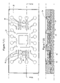
- FIG. 6 ( 1 ) shows a top view of an alternative embodiment of the integrated circuit package 20 of the present invention
- plating option 2 an initial layer of flash Cu is deposited on the copper substrate, followed by an etch barrier of palladium (Pd), followed by layers of Ni, Cu, Ni, and Pd, as shown in FIG. 1 C( 4 ).
- plating option 3 an initial layer of flash Cu is deposited on the copper substrate, followed by an etch barrier of Ag, followed by layers of Cu and Ag, as shown in FIG. 1 C( 5 ).
- plating option 5 an initial layer of Cu is deposited on the copper substrate, followed by Ag, as shown in FIG. 1 C( 7 ).
- the metal strip 30 including the components, the semiconductor dice 26 and wires 38 , is placed in a mold with a flat plate bottom, molded in an overmold material 28 and cured.
- solder balls 42 are then fixed to the exposed contact pads 24 and the exposed portions of the die attach pads 22 , as shown in FIG. 1I , which shows a sectional side view of the resulting package.
- a flux is first added to the solder balls 42 and, after placement in position in the etch down cavities that remain after forming the solder mask 40 , the solder balls 42 are reflowed using known reflow techniques.
- the solder balls 42 thus provide electrical connections from the semiconductor dice 26 , through the wires 38 and the contact pads 24 and from the die attach pads 22 . Excess flux is removed by cleaning with a suitable cleaner.
- FIGS. 2A to 2J describe the processing steps for fabricating an integrated circuit package 20 according to another embodiment of the present invention. Many of the steps for fabricating the integrated circuit package 20 of FIGS. 2A to 2J are similar to the steps for fabricating the integrated circuit package 20 of FIGS. 1A to 1J described above.
- a plating mask 32 is then established on one surface of the metal strip 30 , as shown in FIGS. 2 B( 1 ) and 2 B( 2 ), which show a top view and a sectional side view along the line 2 - 2 of FIG. 2 B( 1 ), respectively, of the metal strip 30 including the plating mask 32 .
- the plating mask 32 is established in the same manner that the plating mask 32 is established in the first described embodiment. In the present embodiment, however, the plating mask 32 defines a single die attach pad 22 , the contact pads 24 , an inductor 34 , a capacitor 36 and a circuit pattern in the form of circuit traces 44 that extend from each of the contact pads 24 , and end proximal the die attach pad 22 .
- FIGS. 2 C( 1 ) and 2 C( 2 ) show a top view and a sectional side view taken along the line 2 - 2 of FIG. 2 C( 1 ), respectively, of the metal strip 30 with the deposited metal layers.
- the plating options in the present embodiment are similar to those of the first described embodiment and are shown in FIGS. 2 C( 3 ) to 2 C( 7 ).
- a singulated semiconductor die 26 is mounted to the die attach pad 22 , using known techniques, as shown in FIGS. 2 E( 1 ) and 2 E( 2 ) which show a top view and a sectional side view along the line 2 - 2 of FIG. 2 E( 1 ), respectively.
- solder balls 42 are then fixed to the exposed contact pads 24 and the exposed portions of the die attach pad 22 , as shown in FIG. 2I , which shows a sectional side view of the resulting package.
- the etch down cavities provide good shear strength of solder balls 42 fixed within the etch down cavities.
- the solder mask 40 under the inductor 34 , the capacitor 36 and portions of the die attach pad 22 is better retained because of the etch down cavity formed, thereby protecting these components from the environment.
- Singulation of the individual integrated circuit package 20 from the remaining packages is then performed either by saw singulation or die punching, resulting in the configuration shown in FIG. 2J .
- FIGS. 3A to 3J describe the processing steps for fabricating an integrated circuit package 20 according to still another embodiment of the present invention. Many of the steps for fabricating the integrated circuit package 20 of FIGS. 3A to 3J are similar to the steps for fabricating the integrated circuit package 20 of FIGS. 2A to 2J described above.
- FIG. 3 A( 1 ) shows a top view of the metal strip 30
- FIG. 3 A( 2 ) shows a side view of the metal strip 30
- the metal strip 30 of the present embodiment is similar to the metal strip 30 previously described and therefore is not further described herein.
- a plating mask 32 is then established on one surface of the metal strip 30 , as shown in FIGS. 3 B( 1 ) and 3 B( 2 ), which show a top view and a sectional side view along the line 2 - 2 of FIG. 3 B( 1 ), respectively, of the metal strip 30 including the plating mask 32 .
- the plating mask 32 is established in the same manner that the plating mask 32 is established in the first described embodiment. In the present embodiment, however, the plating mask 32 defines a single die attach pad 22 , the contact pads 24 , an inductor, a capacitor and a circuit pattern in the form of circuit traces 44 that extend from each of the contact pads 24 , and end proximal the die attach pad 22 . Additional circuit traces 46 also extend from the inductor to an end proximal the die attach pad 22 and from the capacitor to an end proximal the die attach pad 22 .
- FIGS. 3 C( 1 ) and 3 C( 2 ) show a top view and a sectional side view taken along the line 2 - 2 of FIG. 3 C( 1 ), respectively, of the metal strip 30 with the deposited metal layers.
- the plating options in the present embodiment are similar to those of the first described embodiment. However, in the present embodiment, an additional masking proves is carried out to provide contacts for mounting the flip-chop semiconductor die, for example, in the case of plating option 1 , the first four layers of Cu, Au, Ni and Cu are deposited.
- a second plating mask 48 is added to define contacts 49 on the die attach pad 22 , the circuit traces 44 and the circuit traces 46 . The remaining two metal layers of Ni and Au are then deposited to form contacts 49 .
- the plating mask 32 is stripped away by conventional means resulting in the metal strip 30 with the die attach pad 22 , contact pads 24 , inductor, capacitor, circuit traces 44 and circuit traces 46 formed thereon.
- the metal strip 30 and the components with the plating mask 32 stripped away are shown in FIGS. 3 D( 1 ) and 3 D( 2 ), which show a top view and a sectional side view along the line 2 - 2 of FIG. 3 D( 1 ), respectively, of the metal strip 30 without the plating mask 32 .
- the contacts 49 protrude from the remainder of the deposited metal layers of the die attach pad 22 , the circuit traces 44 and the circuit traces 46 .
- FIGS. 3 E( 1 ) and 3 E( 2 ) show a top view and a sectional side view along the line 2 - 2 of FIG. 3 E( 1 ), respectively.
- a singulated semiconductor die 26 is mounted to the die attach pad 22 , in a flip-chip orientation, using known techniques. In this orientation, the semiconductor die 26 is attached to the contacts 49 of the die attach pad 22 , the circuit traces 44 and the circuit traces 46 by direct solder attach of pads of the semiconductor die 26 to the contacts 49 . Thus, the pads of the semiconductor die 26 are electrically connected to the die attach pad 22 , the circuit traces 44 and the circuit traces 46 .
- FIGS. 3 F( 1 ) and 3 F( 2 ) show a top view and a sectional side view taken along the line 2 - 2 of FIG. 3 F( 1 ), respectively.
- the metal strip 30 is etched away by subjecting the metal strip 30 to al alkaline etch using a full immersion etch, leaving etch down cavities at each of the die attach pad 22 , the contact pads 24 , the inductor, the capacitor, the circuit traces 44 and the circuit traces 46 .
- the resulting package is shown in FIGS. 3 G( 1 ) and 3 G( 2 ), which show a bottom view and a sectional side view taken along line 2 - 2 of FIG. 3 G( 1 ), respectively.
- a dielectric material 50 is selectively deposited between plates of the capacitor 36 , as shown in FIGS. 4 E( 1 ), 4 E( 2 ) and 4 E( 3 ), which show a top view, a sectional side view taken along the line 2 - 2 and a sectional side view taken along the line 3 - 3 of FIG. 4 E( 1 ), respectively of the metal strip 30 including the capacitor 36 with the dielectric material 50 disposed between the plates of the capacitor 36 .
- the dielectric material 50 is an electrically non-conductive epoxy that is selectively screen printed between the plates of the capacitor 36 .
- Other dielectric materials are possible, however.
- FIGS. 5A to 5D describe the process steps for fabricating an inductor 34 , in accordance with still another embodiment of the present invention. Some of the steps for fabricating the inductor 34 of FIGS. 5A to 5D are similar to the steps for fabricating the capacitor 36 of FIGS. 4A to 4E described above.
- a plating mask 32 is then established on one surface of the metal strip 30 , as shown in FIGS. 5 B( 1 ) and 5 B( 2 ), which show a top view and a sectional side view taken along the line 2 - 2 of FIG. 5 B( 1 ), respectively, of the metal strip 30 including the plating mask 32 .
- the plating mask 32 is established in the same manner that the plating mask 32 is established in the above described embodiments. In the present embodiment, however, the plating mask 32 defines the inductor 34 only.
- the plating mask 32 is stripped away by conventional means resulting in the metal strip 30 with the inductor 34 formed thereon.
- the metal strip 30 and the inductor 34 with the plating mask 32 stripped away are shown in FIGS. 5 D( 1 ) and 5 D( 2 ), which show a top view and a sectional side view taken along the line 2 - 2 of FIG. 5 D( 1 ), respectively, of the metal strip 30 including the inductor 34 with the plating mask 32 stripped away.
- FIG. 6 ( 1 ) shows a top view of integrated circuit package 20 after plating of the metal layers and prior to stripping the plating mask, according to an alternative embodiment of the present invention
- FIG. 6 ( 2 ) shows a sectional side view taken along the line 2 - 2 of FIG. 6 ( 1 ).
- the plating options described above are provided for exemplary purposes and other alternative plating options are also possible.
- the dielectric material disposed between the plates of the capacitor in the embodiment of FIGS. 4A to 4E is not limited to an electrically non-conductive epoxy as other dielectric materials can be used.
- a molding compound can be used as the dielectric material.
Abstract
Description
Claims (15)
Priority Applications (1)
| Application Number | Priority Date | Filing Date | Title |
|---|---|---|---|
| US11/071,737 US7482690B1 (en) | 1998-06-10 | 2005-03-03 | Electronic components such as thin array plastic packages and process for fabricating same |
Applications Claiming Priority (5)
| Application Number | Priority Date | Filing Date | Title |
|---|---|---|---|
| US09/095,803 US6229200B1 (en) | 1998-06-10 | 1998-06-10 | Saw-singulated leadless plastic chip carrier |
| US09/288,352 US6498099B1 (en) | 1998-06-10 | 1999-04-08 | Leadless plastic chip carrier with etch back pad singulation |
| US09/802,678 US6933594B2 (en) | 1998-06-10 | 2001-03-09 | Leadless plastic chip carrier with etch back pad singulation |
| US10/757,499 US6964918B1 (en) | 1998-06-10 | 2004-01-15 | Electronic components such as thin array plastic packages and process for fabricating same |
| US11/071,737 US7482690B1 (en) | 1998-06-10 | 2005-03-03 | Electronic components such as thin array plastic packages and process for fabricating same |
Related Parent Applications (1)
| Application Number | Title | Priority Date | Filing Date |
|---|---|---|---|
| US10/757,499 Division US6964918B1 (en) | 1998-06-10 | 2004-01-15 | Electronic components such as thin array plastic packages and process for fabricating same |
Publications (1)
| Publication Number | Publication Date |
|---|---|
| US7482690B1 true US7482690B1 (en) | 2009-01-27 |
Family
ID=22253652
Family Applications (6)
| Application Number | Title | Priority Date | Filing Date |
|---|---|---|---|
| US09/095,803 Expired - Lifetime US6229200B1 (en) | 1998-06-10 | 1998-06-10 | Saw-singulated leadless plastic chip carrier |
| US09/363,249 Expired - Lifetime US6242281B1 (en) | 1998-06-10 | 1999-07-28 | Saw-singulated leadless plastic chip carrier |
| US09/793,367 Abandoned US20010030355A1 (en) | 1998-06-10 | 2001-02-26 | Saw-singulated leadless plastic chip carrier |
| US10/026,399 Abandoned US20020056856A1 (en) | 1998-06-10 | 2001-12-21 | Saw singulated leadless plastic chip carrier |
| US10/269,327 Abandoned US20030102537A1 (en) | 1998-06-10 | 2002-10-10 | Saw singulated leadless plastic chip carrier |
| US11/071,737 Expired - Lifetime US7482690B1 (en) | 1998-06-10 | 2005-03-03 | Electronic components such as thin array plastic packages and process for fabricating same |
Family Applications Before (5)
| Application Number | Title | Priority Date | Filing Date |
|---|---|---|---|
| US09/095,803 Expired - Lifetime US6229200B1 (en) | 1998-06-10 | 1998-06-10 | Saw-singulated leadless plastic chip carrier |
| US09/363,249 Expired - Lifetime US6242281B1 (en) | 1998-06-10 | 1999-07-28 | Saw-singulated leadless plastic chip carrier |
| US09/793,367 Abandoned US20010030355A1 (en) | 1998-06-10 | 2001-02-26 | Saw-singulated leadless plastic chip carrier |
| US10/026,399 Abandoned US20020056856A1 (en) | 1998-06-10 | 2001-12-21 | Saw singulated leadless plastic chip carrier |
| US10/269,327 Abandoned US20030102537A1 (en) | 1998-06-10 | 2002-10-10 | Saw singulated leadless plastic chip carrier |
Country Status (1)
| Country | Link |
|---|---|
| US (6) | US6229200B1 (en) |
Cited By (37)
| Publication number | Priority date | Publication date | Assignee | Title |
|---|---|---|---|---|
| US20100127363A1 (en) * | 2006-04-28 | 2010-05-27 | Utac Thai Limited | Very extremely thin semiconductor package |
| US7790512B1 (en) | 2007-11-06 | 2010-09-07 | Utac Thai Limited | Molded leadframe substrate semiconductor package |
| US20100311208A1 (en) * | 2008-05-22 | 2010-12-09 | Utac Thai Limited | Method and apparatus for no lead semiconductor package |
| US20100327432A1 (en) * | 2006-09-26 | 2010-12-30 | Utac Thai Limited | Package with heat transfer |
| US20110039371A1 (en) * | 2008-09-04 | 2011-02-17 | Utac Thai Limited | Flip chip cavity package |
| US20110133319A1 (en) * | 2009-12-04 | 2011-06-09 | Utac Thai Limited | Auxiliary leadframe member for stabilizing the bond wire process |
| US20110147931A1 (en) * | 2006-04-28 | 2011-06-23 | Utac Thai Limited | Lead frame land grid array with routing connector trace under unit |
| US20110198752A1 (en) * | 2006-04-28 | 2011-08-18 | Utac Thai Limited | Lead frame ball grid array with traces under die |
| US8013437B1 (en) | 2006-09-26 | 2011-09-06 | Utac Thai Limited | Package with heat transfer |
| US20110221051A1 (en) * | 2010-03-11 | 2011-09-15 | Utac Thai Limited | Leadframe based multi terminal ic package |
| US20110221049A1 (en) * | 2010-03-12 | 2011-09-15 | Siliconware Precision Industries Co., Ltd. | Quad flat non-leaded semiconductor package and method for fabricating the same |
| US20110232693A1 (en) * | 2009-03-12 | 2011-09-29 | Utac Thai Limited | Metallic solderability preservation coating on metal part of semiconductor package to prevent oxide |
| US8089145B1 (en) * | 2008-11-17 | 2012-01-03 | Amkor Technology, Inc. | Semiconductor device including increased capacity leadframe |
| CN103021890A (en) * | 2012-12-17 | 2013-04-03 | 北京工业大学 | Method for manufacturing QFN (quad flat no-lead) package device |
| CN103021876A (en) * | 2012-12-17 | 2013-04-03 | 北京工业大学 | Method for manufacturing high-density QFN (quad flat no-lead) package device |
| CN103050419A (en) * | 2012-12-17 | 2013-04-17 | 北京工业大学 | Method for manufacturing QFN (quad flat non-lead package) with multiple rings of pin configuration |
| US8461694B1 (en) | 2006-04-28 | 2013-06-11 | Utac Thai Limited | Lead frame ball grid array with traces under die having interlocking features |
| US8460970B1 (en) | 2006-04-28 | 2013-06-11 | Utac Thai Limited | Lead frame ball grid array with traces under die having interlocking features |
| US8508045B2 (en) | 2011-03-03 | 2013-08-13 | Broadcom Corporation | Package 3D interconnection and method of making same |
| TWI453844B (en) * | 2010-03-12 | 2014-09-21 | 矽品精密工業股份有限公司 | Quad flat no-lead package and method for forming the same |
| US8871571B2 (en) | 2010-04-02 | 2014-10-28 | Utac Thai Limited | Apparatus for and methods of attaching heat slugs to package tops |
| US20140338593A1 (en) * | 2011-01-17 | 2014-11-20 | Samsung Electronics Co., Ltd. | Method and apparatus for manufacturing white light-emitting device |
| US20150034995A1 (en) * | 2013-07-31 | 2015-02-05 | Infineon Technologies Austria Ag | Semiconductor device with combined passive device on chip back side |
| US9000590B2 (en) | 2012-05-10 | 2015-04-07 | Utac Thai Limited | Protruding terminals with internal routing interconnections semiconductor device |
| US9006034B1 (en) | 2012-06-11 | 2015-04-14 | Utac Thai Limited | Post-mold for semiconductor package having exposed traces |
| US9064781B2 (en) | 2011-03-03 | 2015-06-23 | Broadcom Corporation | Package 3D interconnection and method of making same |
| US9082607B1 (en) | 2006-12-14 | 2015-07-14 | Utac Thai Limited | Molded leadframe substrate semiconductor package |
| US9355940B1 (en) | 2009-12-04 | 2016-05-31 | Utac Thai Limited | Auxiliary leadframe member for stabilizing the bond wire process |
| US20160218021A1 (en) * | 2015-01-27 | 2016-07-28 | Advanced Semiconductor Engineering, Inc. | Semiconductor package and method of manufacturing the same |
| US9449905B2 (en) | 2012-05-10 | 2016-09-20 | Utac Thai Limited | Plated terminals with routing interconnections semiconductor device |
| US9449900B2 (en) | 2009-07-23 | 2016-09-20 | UTAC Headquarters Pte. Ltd. | Leadframe feature to minimize flip-chip semiconductor die collapse during flip-chip reflow |
| US20160293452A1 (en) * | 2015-03-31 | 2016-10-06 | Renesas Electronics Corporation | Method for manufacturing a semiconductor device |
| US9761435B1 (en) | 2006-12-14 | 2017-09-12 | Utac Thai Limited | Flip chip cavity package |
| US9805955B1 (en) | 2015-11-10 | 2017-10-31 | UTAC Headquarters Pte. Ltd. | Semiconductor package with multiple molding routing layers and a method of manufacturing the same |
| US10242953B1 (en) | 2015-05-27 | 2019-03-26 | Utac Headquarters PTE. Ltd | Semiconductor package with plated metal shielding and a method thereof |
| US10242934B1 (en) | 2014-05-07 | 2019-03-26 | Utac Headquarters Pte Ltd. | Semiconductor package with full plating on contact side surfaces and methods thereof |
| US10276477B1 (en) | 2016-05-20 | 2019-04-30 | UTAC Headquarters Pte. Ltd. | Semiconductor package with multiple stacked leadframes and a method of manufacturing the same |
Families Citing this family (270)
| Publication number | Priority date | Publication date | Assignee | Title |
|---|---|---|---|---|
| US6130473A (en) * | 1998-04-02 | 2000-10-10 | National Semiconductor Corporation | Lead frame chip scale package |
| US7271032B1 (en) | 1998-06-10 | 2007-09-18 | Asat Ltd. | Leadless plastic chip carrier with etch back pad singulation |
| US7270867B1 (en) | 1998-06-10 | 2007-09-18 | Asat Ltd. | Leadless plastic chip carrier |
| US6989294B1 (en) | 1998-06-10 | 2006-01-24 | Asat, Ltd. | Leadless plastic chip carrier with etch back pad singulation |
| US6933594B2 (en) * | 1998-06-10 | 2005-08-23 | Asat Ltd. | Leadless plastic chip carrier with etch back pad singulation |
| US6498099B1 (en) * | 1998-06-10 | 2002-12-24 | Asat Ltd. | Leadless plastic chip carrier with etch back pad singulation |
| US7247526B1 (en) | 1998-06-10 | 2007-07-24 | Asat Ltd. | Process for fabricating an integrated circuit package |
| US7226811B1 (en) | 1998-06-10 | 2007-06-05 | Asat Ltd. | Process for fabricating a leadless plastic chip carrier |
| US7049177B1 (en) | 2004-01-28 | 2006-05-23 | Asat Ltd. | Leadless plastic chip carrier with standoff contacts and die attach pad |
| US8330270B1 (en) | 1998-06-10 | 2012-12-11 | Utac Hong Kong Limited | Integrated circuit package having a plurality of spaced apart pad portions |
| US6229200B1 (en) * | 1998-06-10 | 2001-05-08 | Asat Limited | Saw-singulated leadless plastic chip carrier |
| US7332375B1 (en) * | 1998-06-24 | 2008-02-19 | Amkor Technology, Inc. | Method of making an integrated circuit package |
| US7005326B1 (en) * | 1998-06-24 | 2006-02-28 | Amkor Technology, Inc. | Method of making an integrated circuit package |
| US6143981A (en) | 1998-06-24 | 2000-11-07 | Amkor Technology, Inc. | Plastic integrated circuit package and method and leadframe for making the package |
| US6281568B1 (en) | 1998-10-21 | 2001-08-28 | Amkor Technology, Inc. | Plastic integrated circuit device package and leadframe having partially undercut leads and die pad |
| US6448633B1 (en) * | 1998-11-20 | 2002-09-10 | Amkor Technology, Inc. | Semiconductor package and method of making using leadframe having lead locks to secure leads to encapsulant |
| US6274927B1 (en) | 1999-06-03 | 2001-08-14 | Amkor Technology, Inc. | Plastic package for an optical integrated circuit device and method of making |
| MY133357A (en) * | 1999-06-30 | 2007-11-30 | Hitachi Ltd | A semiconductor device and a method of manufacturing the same |
| KR200309906Y1 (en) * | 1999-06-30 | 2003-04-14 | 앰코 테크놀로지 코리아 주식회사 | lead frame for fabricating semiconductor package |
| US20020100165A1 (en) | 2000-02-14 | 2002-08-01 | Amkor Technology, Inc. | Method of forming an integrated circuit device package using a temporary substrate |
| JP3461332B2 (en) * | 1999-09-10 | 2003-10-27 | 松下電器産業株式会社 | Lead frame, resin package and optoelectronic device using the same |
| KR100526844B1 (en) * | 1999-10-15 | 2005-11-08 | 앰코 테크놀로지 코리아 주식회사 | semiconductor package and its manufacturing method |
| KR20010037254A (en) * | 1999-10-15 | 2001-05-07 | 마이클 디. 오브라이언 | Semiconductor package |
| US6525406B1 (en) * | 1999-10-15 | 2003-02-25 | Amkor Technology, Inc. | Semiconductor device having increased moisture path and increased solder joint strength |
| KR100364978B1 (en) | 1999-10-15 | 2002-12-16 | 앰코 테크놀로지 코리아 주식회사 | Clamp and Heat Block for Wire Bonding in Semiconductor Package |
| KR100403142B1 (en) | 1999-10-15 | 2003-10-30 | 앰코 테크놀로지 코리아 주식회사 | semiconductor package |
| KR100355796B1 (en) | 1999-10-15 | 2002-10-19 | 앰코 테크놀로지 코리아 주식회사 | structure of leadframe for semiconductor package and mold for molding the same |
| KR20010037252A (en) | 1999-10-15 | 2001-05-07 | 마이클 디. 오브라이언 | Mold for manufacturing semiconductor package |
| KR100355795B1 (en) | 1999-10-15 | 2002-10-19 | 앰코 테크놀로지 코리아 주식회사 | manufacturing method of semiconductor package |
| KR100355794B1 (en) | 1999-10-15 | 2002-10-19 | 앰코 테크놀로지 코리아 주식회사 | leadframe and semiconductor package using the same |
| KR20010056618A (en) | 1999-12-16 | 2001-07-04 | 프랑크 제이. 마르쿠치 | Semiconductor package |
| KR20010037247A (en) | 1999-10-15 | 2001-05-07 | 마이클 디. 오브라이언 | Semiconductor package |
| US6580159B1 (en) | 1999-11-05 | 2003-06-17 | Amkor Technology, Inc. | Integrated circuit device packages and substrates for making the packages |
| US6847103B1 (en) | 1999-11-09 | 2005-01-25 | Amkor Technology, Inc. | Semiconductor package with exposed die pad and body-locking leadframe |
| US6476478B1 (en) | 1999-11-12 | 2002-11-05 | Amkor Technology, Inc. | Cavity semiconductor package with exposed leads and die pad |
| US6459147B1 (en) * | 2000-03-27 | 2002-10-01 | Amkor Technology, Inc. | Attaching semiconductor dies to substrates with conductive straps |
| KR100421774B1 (en) * | 1999-12-16 | 2004-03-10 | 앰코 테크놀로지 코리아 주식회사 | semiconductor package and its manufacturing method |
| US6639308B1 (en) * | 1999-12-16 | 2003-10-28 | Amkor Technology, Inc. | Near chip size semiconductor package |
| KR100426494B1 (en) | 1999-12-20 | 2004-04-13 | 앰코 테크놀로지 코리아 주식회사 | Semiconductor package and its manufacturing method |
| KR20010058583A (en) | 1999-12-30 | 2001-07-06 | 마이클 디. 오브라이언 | Lead End Grid Array Semiconductor package |
| US6949822B2 (en) * | 2000-03-17 | 2005-09-27 | International Rectifier Corporation | Semiconductor multichip module package with improved thermal performance; reduced size and improved moisture resistance |
| KR100583494B1 (en) * | 2000-03-25 | 2006-05-24 | 앰코 테크놀로지 코리아 주식회사 | Semiconductor package |
| KR100559664B1 (en) | 2000-03-25 | 2006-03-10 | 앰코 테크놀로지 코리아 주식회사 | Semiconductor package |
| TW447096B (en) * | 2000-04-01 | 2001-07-21 | Siliconware Precision Industries Co Ltd | Semiconductor packaging with exposed die |
| US7042068B2 (en) | 2000-04-27 | 2006-05-09 | Amkor Technology, Inc. | Leadframe and semiconductor package made using the leadframe |
| US6518659B1 (en) | 2000-05-08 | 2003-02-11 | Amkor Technology, Inc. | Stackable package having a cavity and a lid for an electronic device |
| US6424031B1 (en) | 2000-05-08 | 2002-07-23 | Amkor Technology, Inc. | Stackable package with heat sink |
| JP2001320007A (en) * | 2000-05-09 | 2001-11-16 | Dainippon Printing Co Ltd | Frame for resin sealed semiconductor device |
| JP4349541B2 (en) | 2000-05-09 | 2009-10-21 | 大日本印刷株式会社 | Resin-encapsulated semiconductor device frame |
| JP4840893B2 (en) * | 2000-05-12 | 2011-12-21 | 大日本印刷株式会社 | Resin-encapsulated semiconductor device frame |
| US6667544B1 (en) | 2000-06-30 | 2003-12-23 | Amkor Technology, Inc. | Stackable package having clips for fastening package and tool for opening clips |
| US6867483B2 (en) * | 2000-09-13 | 2005-03-15 | Carsen Semiconductor Sdn. Bhd. | Stress-free lead frame |
| US7288833B2 (en) * | 2000-09-13 | 2007-10-30 | Carsem (M) Sdn. Bhd. | Stress-free lead frame |
| SG112799A1 (en) * | 2000-10-09 | 2005-07-28 | St Assembly Test Services Ltd | Leaded semiconductor packages and method of trimming and singulating such packages |
| US6454046B1 (en) | 2000-10-27 | 2002-09-24 | Po-An Chuang | Synchronous dustproof cover structure for sound membrane |
| US6448107B1 (en) * | 2000-11-28 | 2002-09-10 | National Semiconductor Corporation | Pin indicator for leadless leadframe packages |
| KR20020058209A (en) | 2000-12-29 | 2002-07-12 | 마이클 디. 오브라이언 | Semiconductor package |
| KR100731007B1 (en) * | 2001-01-15 | 2007-06-22 | 앰코 테크놀로지 코리아 주식회사 | stack-type semiconductor package |
| KR100394030B1 (en) * | 2001-01-15 | 2003-08-06 | 앰코 테크놀로지 코리아 주식회사 | stack-type semiconductor package |
| US6424024B1 (en) * | 2001-01-23 | 2002-07-23 | Siliconware Precision Industries Co., Ltd. | Leadframe of quad flat non-leaded package |
| US6674156B1 (en) * | 2001-02-09 | 2004-01-06 | National Semiconductor Corporation | Multiple row fine pitch leadless leadframe package with use of half-etch process |
| US6661083B2 (en) | 2001-02-27 | 2003-12-09 | Chippac, Inc | Plastic semiconductor package |
| US6545347B2 (en) * | 2001-03-06 | 2003-04-08 | Asat, Limited | Enhanced leadless chip carrier |
| US6605865B2 (en) | 2001-03-19 | 2003-08-12 | Amkor Technology, Inc. | Semiconductor package with optimized leadframe bonding strength |
| US6545345B1 (en) | 2001-03-20 | 2003-04-08 | Amkor Technology, Inc. | Mounting for a package containing a chip |
| KR100369393B1 (en) | 2001-03-27 | 2003-02-05 | 앰코 테크놀로지 코리아 주식회사 | Lead frame and semiconductor package using it and its manufacturing method |
| KR100393448B1 (en) | 2001-03-27 | 2003-08-02 | 앰코 테크놀로지 코리아 주식회사 | Semiconductor package and method for manufacturing the same |
| US6756658B1 (en) | 2001-04-06 | 2004-06-29 | Amkor Technology, Inc. | Making two lead surface mounting high power microleadframe semiconductor packages |
| US6614102B1 (en) | 2001-05-04 | 2003-09-02 | Amkor Technology, Inc. | Shielded semiconductor leadframe package |
| DE10124970B4 (en) * | 2001-05-21 | 2007-02-22 | Infineon Technologies Ag | Electronic component with a semiconductor chip on a semiconductor chip connection plate, system carrier and method for the production thereof |
| US6668449B2 (en) * | 2001-06-25 | 2003-12-30 | Micron Technology, Inc. | Method of making a semiconductor device having an opening in a solder mask |
| US20040053447A1 (en) * | 2001-06-29 | 2004-03-18 | Foster Donald Craig | Leadframe having fine pitch bond fingers formed using laser cutting method |
| DE10132385B4 (en) * | 2001-07-06 | 2006-07-13 | Infineon Technologies Ag | Electronic component, a utility and a system support for such a component with distributed on its undersides outer contacts, and method for producing the same |
| US6734552B2 (en) | 2001-07-11 | 2004-05-11 | Asat Limited | Enhanced thermal dissipation integrated circuit package |
| US7015072B2 (en) | 2001-07-11 | 2006-03-21 | Asat Limited | Method of manufacturing an enhanced thermal dissipation integrated circuit package |
| SG120858A1 (en) * | 2001-08-06 | 2006-04-26 | Micron Technology Inc | Quad flat no-lead (qfn) grid array package, methodof making and memory module and computer system including same |
| DE10137956A1 (en) * | 2001-08-07 | 2002-10-31 | Infineon Technologies Ag | Electronic component comprises a semiconductor chip on an island embedded in a flat plastic housing having an exposed surface of the island in the center of its lower side and metallic external edge contacts arranged on its edge sides |
| US6790710B2 (en) * | 2002-01-31 | 2004-09-14 | Asat Limited | Method of manufacturing an integrated circuit package |
| US7102216B1 (en) | 2001-08-17 | 2006-09-05 | Amkor Technology, Inc. | Semiconductor package and leadframe with horizontal leads spaced in the vertical direction and method of making |
| US6856007B2 (en) * | 2001-08-28 | 2005-02-15 | Tessera, Inc. | High-frequency chip packages |
| US7176506B2 (en) * | 2001-08-28 | 2007-02-13 | Tessera, Inc. | High frequency chip packages with connecting elements |
| DE10243947B4 (en) * | 2001-09-20 | 2007-02-01 | Infineon Technologies Ag | Electronic component with at least one semiconductor chip and method for its production |
| DE10147375B4 (en) * | 2001-09-26 | 2006-06-08 | Infineon Technologies Ag | Electronic component with a semiconductor chip and method for producing the same |
| DE10147376B4 (en) * | 2001-09-26 | 2009-01-15 | Infineon Technologies Ag | Electronic component and leadframe and method for producing the same |
| DE10148120B4 (en) * | 2001-09-28 | 2007-02-01 | Infineon Technologies Ag | Electronic components with semiconductor chips and a system carrier with component positions and method for producing a system carrier |
| US6555917B1 (en) | 2001-10-09 | 2003-04-29 | Amkor Technology, Inc. | Semiconductor package having stacked semiconductor chips and method of making the same |
| US6611047B2 (en) * | 2001-10-12 | 2003-08-26 | Amkor Technology, Inc. | Semiconductor package with singulation crease |
| US6630726B1 (en) | 2001-11-07 | 2003-10-07 | Amkor Technology, Inc. | Power semiconductor package with strap |
| US6686651B1 (en) | 2001-11-27 | 2004-02-03 | Amkor Technology, Inc. | Multi-layer leadframe structure |
| KR100781149B1 (en) * | 2001-12-21 | 2007-11-30 | 삼성테크윈 주식회사 | Lead-frame strip and process for manufacturing semiconductor packages using the same |
| US6798046B1 (en) | 2002-01-22 | 2004-09-28 | Amkor Technology, Inc. | Semiconductor package including ring structure connected to leads with vertically downset inner ends |
| TW533566B (en) * | 2002-01-31 | 2003-05-21 | Siliconware Precision Industries Co Ltd | Short-prevented lead frame and method for fabricating semiconductor package with the same |
| US6885086B1 (en) | 2002-03-05 | 2005-04-26 | Amkor Technology, Inc. | Reduced copper lead frame for saw-singulated chip package |
| US6838751B2 (en) * | 2002-03-06 | 2005-01-04 | Freescale Semiconductor Inc. | Multi-row leadframe |
| US20030178719A1 (en) * | 2002-03-22 | 2003-09-25 | Combs Edward G. | Enhanced thermal dissipation integrated circuit package and method of manufacturing enhanced thermal dissipation integrated circuit package |
| US6608366B1 (en) | 2002-04-15 | 2003-08-19 | Harry J. Fogelson | Lead frame with plated end leads |
| US6667073B1 (en) | 2002-05-07 | 2003-12-23 | Quality Platers Limited | Leadframe for enhanced downbond registration during automatic wire bond process |
| US6627977B1 (en) | 2002-05-09 | 2003-09-30 | Amkor Technology, Inc. | Semiconductor package including isolated ring structure |
| US6734044B1 (en) | 2002-06-10 | 2004-05-11 | Asat Ltd. | Multiple leadframe laminated IC package |
| US6841414B1 (en) | 2002-06-19 | 2005-01-11 | Amkor Technology, Inc. | Saw and etch singulation method for a chip package |
| US6940154B2 (en) * | 2002-06-24 | 2005-09-06 | Asat Limited | Integrated circuit package and method of manufacturing the integrated circuit package |
| US6867071B1 (en) | 2002-07-12 | 2005-03-15 | Amkor Technology, Inc. | Leadframe including corner leads and semiconductor package using same |
| TW560026B (en) * | 2002-08-27 | 2003-11-01 | Uni Tek System Inc | Singulation method of the array-type work piece to be singulated having metal layer singulation street, and the array-type work piece to be singulated applying the method |
| US7061077B2 (en) * | 2002-08-30 | 2006-06-13 | Fairchild Semiconductor Corporation | Substrate based unmolded package including lead frame structure and semiconductor die |
| US7732914B1 (en) | 2002-09-03 | 2010-06-08 | Mclellan Neil | Cavity-type integrated circuit package |
| US6821817B1 (en) | 2002-09-03 | 2004-11-23 | Asat Ltd. | Premolded cavity IC package |
| US6818973B1 (en) | 2002-09-09 | 2004-11-16 | Amkor Technology, Inc. | Exposed lead QFP package fabricated through the use of a partial saw process |
| US6794738B2 (en) | 2002-09-23 | 2004-09-21 | Texas Instruments Incorporated | Leadframe-to-plastic lock for IC package |
| US6905914B1 (en) | 2002-11-08 | 2005-06-14 | Amkor Technology, Inc. | Wafer level package and fabrication method |
| US7723210B2 (en) | 2002-11-08 | 2010-05-25 | Amkor Technology, Inc. | Direct-write wafer level chip scale package |
| US8129222B2 (en) * | 2002-11-27 | 2012-03-06 | United Test And Assembly Test Center Ltd. | High density chip scale leadframe package and method of manufacturing the package |
| US6872599B1 (en) * | 2002-12-10 | 2005-03-29 | National Semiconductor Corporation | Enhanced solder joint strength and ease of inspection of leadless leadframe package (LLP) |
| US7071545B1 (en) | 2002-12-20 | 2006-07-04 | Asat Ltd. | Shielded integrated circuit package |
| US6798047B1 (en) | 2002-12-26 | 2004-09-28 | Amkor Technology, Inc. | Pre-molded leadframe |
| US7271493B2 (en) * | 2003-01-21 | 2007-09-18 | Siliconware Precision Industries Co., Ltd. | Semiconductor package free of substrate and fabrication method thereof |
| US7423340B2 (en) * | 2003-01-21 | 2008-09-09 | Siliconware Precision Industries Co., Ltd. | Semiconductor package free of substrate and fabrication method thereof |
| US20050184368A1 (en) * | 2003-01-21 | 2005-08-25 | Huang Chien P. | Semiconductor package free of substrate and fabrication method thereof |
| US7342318B2 (en) * | 2003-01-21 | 2008-03-11 | Siliconware Precision Industries Co., Ltd. | Semiconductor package free of substrate and fabrication method thereof |
| TWI241000B (en) * | 2003-01-21 | 2005-10-01 | Siliconware Precision Industries Co Ltd | Semiconductor package and fabricating method thereof |
| US20050194665A1 (en) * | 2003-01-21 | 2005-09-08 | Huang Chien P. | Semiconductor package free of substrate and fabrication method thereof |
| US7002239B1 (en) * | 2003-02-14 | 2006-02-21 | National Semiconductor Corporation | Leadless leadframe packaging panel featuring peripheral dummy leads |
| US6750545B1 (en) | 2003-02-28 | 2004-06-15 | Amkor Technology, Inc. | Semiconductor package capable of die stacking |
| US6927483B1 (en) * | 2003-03-07 | 2005-08-09 | Amkor Technology, Inc. | Semiconductor package exhibiting efficient lead placement |
| TW200418149A (en) * | 2003-03-11 | 2004-09-16 | Siliconware Precision Industries Co Ltd | Surface-mount-enhanced lead frame and method for fabricating semiconductor package with the same |
| US6794740B1 (en) | 2003-03-13 | 2004-09-21 | Amkor Technology, Inc. | Leadframe package for semiconductor devices |
| WO2004097896A2 (en) * | 2003-04-26 | 2004-11-11 | Freescale Semiconductor, Inc. | A packaged integrated circuit having a heat spreader and method therefor |
| TW200425427A (en) * | 2003-05-02 | 2004-11-16 | Siliconware Precision Industries Co Ltd | Leadframe-based non-leaded semiconductor package and method of fabricating the same |
| US6894376B1 (en) | 2003-06-09 | 2005-05-17 | National Semiconductor Corporation | Leadless microelectronic package and a method to maximize the die size in the package |
| WO2005004195A2 (en) * | 2003-07-03 | 2005-01-13 | Shellcase Ltd. | Method and apparatus for packaging integrated circuit devices |
| CN1571130B (en) * | 2003-07-15 | 2010-04-28 | 品质有限公司 | Lead frame for reinforcing lower joint alignment in automatic lead bonding process |
| DE10332017A1 (en) * | 2003-07-14 | 2005-03-03 | Infineon Technologies Ag | Electronic component and leadframe for the manufacture of the component |
| US6815806B1 (en) | 2003-07-17 | 2004-11-09 | International Business Machines Corp. | Asymmetric partially-etched leads for finer pitch semiconductor chip package |
| US8211753B2 (en) * | 2003-08-26 | 2012-07-03 | Stats Chippac Ltd. | Leadframe-based mold array package heat spreader and fabrication method therefor |
| US6903304B1 (en) | 2003-09-12 | 2005-06-07 | Asat Ltd. | Process for dressing molded array package saw blade |
| US7033517B1 (en) | 2003-09-15 | 2006-04-25 | Asat Ltd. | Method of fabricating a leadless plastic chip carrier |
| US6936922B1 (en) | 2003-09-26 | 2005-08-30 | Amkor Technology, Inc. | Semiconductor package structure reducing warpage and manufacturing method thereof |
| WO2005031862A1 (en) * | 2003-09-26 | 2005-04-07 | Tessera, Inc. | Structure and method of making sealed capped chips |
| US6977431B1 (en) | 2003-11-05 | 2005-12-20 | Amkor Technology, Inc. | Stackable semiconductor package and manufacturing method thereof |
| US20050139984A1 (en) * | 2003-12-19 | 2005-06-30 | Tessera, Inc. | Package element and packaged chip having severable electrically conductive ties |
| US20050146057A1 (en) * | 2003-12-31 | 2005-07-07 | Khor Ah L. | Micro lead frame package having transparent encapsulant |
| US7009286B1 (en) | 2004-01-15 | 2006-03-07 | Asat Ltd. | Thin leadless plastic chip carrier |
| TWM253056U (en) * | 2004-02-13 | 2004-12-11 | Optimum Care Int Tech Inc | Compact chip packaging structure |
| US7053469B2 (en) * | 2004-03-30 | 2006-05-30 | Advanced Semiconductor Engineering, Inc. | Leadless semiconductor package and manufacturing method thereof |
| US7196313B2 (en) * | 2004-04-02 | 2007-03-27 | Fairchild Semiconductor Corporation | Surface mount multi-channel optocoupler |
| KR101070890B1 (en) * | 2004-04-16 | 2011-10-06 | 삼성테크윈 주식회사 | Method for manufacturing the semiconductor package of multi-row lead type |
| TWI244169B (en) * | 2004-05-12 | 2005-11-21 | Siliconware Precision Industries Co Ltd | High electric performance semiconductor package |
| US7411289B1 (en) | 2004-06-14 | 2008-08-12 | Asat Ltd. | Integrated circuit package with partially exposed contact pads and process for fabricating the same |
| US7091581B1 (en) | 2004-06-14 | 2006-08-15 | Asat Limited | Integrated circuit package and process for fabricating the same |
| US7186588B1 (en) | 2004-06-18 | 2007-03-06 | National Semiconductor Corporation | Method of fabricating a micro-array integrated circuit package |
| US7087986B1 (en) | 2004-06-18 | 2006-08-08 | National Semiconductor Corporation | Solder pad configuration for use in a micro-array integrated circuit package |
| US7259460B1 (en) | 2004-06-18 | 2007-08-21 | National Semiconductor Corporation | Wire bonding on thinned portions of a lead-frame configured for use in a micro-array integrated circuit package |
| US7064419B1 (en) | 2004-06-18 | 2006-06-20 | National Semiconductor Corporation | Die attach region for use in a micro-array integrated circuit package |
| US7595225B1 (en) | 2004-10-05 | 2009-09-29 | Chun Ho Fan | Leadless plastic chip carrier with contact standoff |
| US7358119B2 (en) * | 2005-01-12 | 2008-04-15 | Asat Ltd. | Thin array plastic package without die attach pad and process for fabricating the same |
| JP2008532278A (en) | 2005-02-23 | 2008-08-14 | エヌエックスピー ビー ヴィ | Integrated circuit package device, lead frame and electronic device with additional contact pads |
| WO2006090304A1 (en) | 2005-02-23 | 2006-08-31 | Nxp B.V. | An integrated circuit package device with improved bond pad connections, a leadframe and an electronic device |
| US8143095B2 (en) | 2005-03-22 | 2012-03-27 | Tessera, Inc. | Sequential fabrication of vertical conductive interconnects in capped chips |
| US7498665B2 (en) * | 2005-05-05 | 2009-03-03 | Stats Chippac Ltd. | Integrated circuit leadless package system |
| JP2008545274A (en) * | 2005-06-30 | 2008-12-11 | フェアチャイルド セミコンダクター コーポレイション | Semiconductor die package and manufacturing method thereof |
| US7348663B1 (en) | 2005-07-15 | 2008-03-25 | Asat Ltd. | Integrated circuit package and method for fabricating same |
| US8786165B2 (en) * | 2005-09-16 | 2014-07-22 | Tsmc Solid State Lighting Ltd. | QFN/SON compatible package with SMT land pads |
| US7410830B1 (en) | 2005-09-26 | 2008-08-12 | Asat Ltd | Leadless plastic chip carrier and method of fabricating same |
| US7943431B2 (en) * | 2005-12-02 | 2011-05-17 | Unisem (Mauritius) Holdings Limited | Leadless semiconductor package and method of manufacture |
| US7507603B1 (en) | 2005-12-02 | 2009-03-24 | Amkor Technology, Inc. | Etch singulated semiconductor package |
| KR101135828B1 (en) * | 2005-12-08 | 2012-04-16 | 페어차일드 세미컨덕터 코포레이션 | Flip chip mlp with conductive ink |
| EP1795496A2 (en) * | 2005-12-08 | 2007-06-13 | Yamaha Corporation | Semiconductor device for detecting pressure variations |
| US7572681B1 (en) | 2005-12-08 | 2009-08-11 | Amkor Technology, Inc. | Embedded electronic component package |
| US7936062B2 (en) | 2006-01-23 | 2011-05-03 | Tessera Technologies Ireland Limited | Wafer level chip packaging |
| US20080002460A1 (en) * | 2006-03-01 | 2008-01-03 | Tessera, Inc. | Structure and method of making lidded chips |
| US7986043B2 (en) * | 2006-03-08 | 2011-07-26 | Stats Chippac Ltd. | Integrated circuit package on package system |
| US7981702B2 (en) | 2006-03-08 | 2011-07-19 | Stats Chippac Ltd. | Integrated circuit package in package system |
| US8513542B2 (en) * | 2006-03-08 | 2013-08-20 | Stats Chippac Ltd. | Integrated circuit leaded stacked package system |
| TWI286375B (en) * | 2006-03-24 | 2007-09-01 | Chipmos Technologies Inc | Leadless semiconductor package with electroplated layer embedded in encapsulant and the method for fabricating the same |
| DE102006015241A1 (en) * | 2006-03-30 | 2007-06-28 | Infineon Technologies Ag | Quad flat non-leaded package semiconductor component, has expansion joint arranged in plastic housing and provided between border angle region and outer contact surfaces of outer contact and central region of housing |
| US7902660B1 (en) | 2006-05-24 | 2011-03-08 | Amkor Technology, Inc. | Substrate for semiconductor device and manufacturing method thereof |
| US7968998B1 (en) | 2006-06-21 | 2011-06-28 | Amkor Technology, Inc. | Side leaded, bottom exposed pad and bottom exposed lead fusion quad flat semiconductor package |
| US20080111219A1 (en) * | 2006-11-14 | 2008-05-15 | Gem Services, Inc. | Package designs for vertical conduction die |
| US20080135991A1 (en) * | 2006-12-12 | 2008-06-12 | Gem Services, Inc. | Semiconductor device package featuring encapsulated leadframe with projecting bumps or balls |
| US7608482B1 (en) * | 2006-12-21 | 2009-10-27 | National Semiconductor Corporation | Integrated circuit package with molded insulation |
| US7687893B2 (en) | 2006-12-27 | 2010-03-30 | Amkor Technology, Inc. | Semiconductor package having leadframe with exposed anchor pads |
| US8604605B2 (en) | 2007-01-05 | 2013-12-10 | Invensas Corp. | Microelectronic assembly with multi-layer support structure |
| US7829990B1 (en) | 2007-01-18 | 2010-11-09 | Amkor Technology, Inc. | Stackable semiconductor package including laminate interposer |
| TW200836315A (en) * | 2007-02-16 | 2008-09-01 | Richtek Techohnology Corp | Electronic package structure and method thereof |
| US7982297B1 (en) | 2007-03-06 | 2011-07-19 | Amkor Technology, Inc. | Stackable semiconductor package having partially exposed semiconductor die and method of fabricating the same |
| US8207600B2 (en) * | 2007-03-30 | 2012-06-26 | Stats Chippac Ltd. | Integrated circuit package system with encapsulating features |
| US7977774B2 (en) | 2007-07-10 | 2011-07-12 | Amkor Technology, Inc. | Fusion quad flat semiconductor package |
| MY154596A (en) | 2007-07-25 | 2015-06-30 | Carsem M Sdn Bhd | Thin plastic leadless package with exposed metal die paddle |
| US7687899B1 (en) | 2007-08-07 | 2010-03-30 | Amkor Technology, Inc. | Dual laminate package structure with embedded elements |
| US7777351B1 (en) | 2007-10-01 | 2010-08-17 | Amkor Technology, Inc. | Thin stacked interposer package |
| US8089159B1 (en) | 2007-10-03 | 2012-01-03 | Amkor Technology, Inc. | Semiconductor package with increased I/O density and method of making the same |
| US7847386B1 (en) | 2007-11-05 | 2010-12-07 | Amkor Technology, Inc. | Reduced size stacked semiconductor package and method of making the same |
| US7948066B2 (en) * | 2007-12-26 | 2011-05-24 | Stats Chippac Ltd. | Integrated circuit package system with lead locking structure |
| US7956453B1 (en) | 2008-01-16 | 2011-06-07 | Amkor Technology, Inc. | Semiconductor package with patterning layer and method of making same |
| US7723852B1 (en) | 2008-01-21 | 2010-05-25 | Amkor Technology, Inc. | Stacked semiconductor package and method of making same |
| US8067821B1 (en) | 2008-04-10 | 2011-11-29 | Amkor Technology, Inc. | Flat semiconductor package with half package molding |
| US7768135B1 (en) | 2008-04-17 | 2010-08-03 | Amkor Technology, Inc. | Semiconductor package with fast power-up cycle and method of making same |
| US7808084B1 (en) | 2008-05-06 | 2010-10-05 | Amkor Technology, Inc. | Semiconductor package with half-etched locking features |
| US8125064B1 (en) | 2008-07-28 | 2012-02-28 | Amkor Technology, Inc. | Increased I/O semiconductor package and method of making same |
| US8184453B1 (en) | 2008-07-31 | 2012-05-22 | Amkor Technology, Inc. | Increased capacity semiconductor package |
| US7847392B1 (en) | 2008-09-30 | 2010-12-07 | Amkor Technology, Inc. | Semiconductor device including leadframe with increased I/O |
| US7989933B1 (en) | 2008-10-06 | 2011-08-02 | Amkor Technology, Inc. | Increased I/O leadframe and semiconductor device including same |
| US8008758B1 (en) | 2008-10-27 | 2011-08-30 | Amkor Technology, Inc. | Semiconductor device with increased I/O leadframe |
| US8072050B1 (en) | 2008-11-18 | 2011-12-06 | Amkor Technology, Inc. | Semiconductor device with increased I/O leadframe including passive device |
| US7875963B1 (en) | 2008-11-21 | 2011-01-25 | Amkor Technology, Inc. | Semiconductor device including leadframe having power bars and increased I/O |
| US7982298B1 (en) | 2008-12-03 | 2011-07-19 | Amkor Technology, Inc. | Package in package semiconductor device |
| US8487420B1 (en) | 2008-12-08 | 2013-07-16 | Amkor Technology, Inc. | Package in package semiconductor device with film over wire |
| US20170117214A1 (en) | 2009-01-05 | 2017-04-27 | Amkor Technology, Inc. | Semiconductor device with through-mold via |
| US8680656B1 (en) | 2009-01-05 | 2014-03-25 | Amkor Technology, Inc. | Leadframe structure for concentrated photovoltaic receiver package |
| US8058715B1 (en) | 2009-01-09 | 2011-11-15 | Amkor Technology, Inc. | Package in package device for RF transceiver module |
| US9899349B2 (en) | 2009-01-29 | 2018-02-20 | Semiconductor Components Industries, Llc | Semiconductor packages and related methods |
| US10199311B2 (en) | 2009-01-29 | 2019-02-05 | Semiconductor Components Industries, Llc | Leadless semiconductor packages, leadframes therefor, and methods of making |
| US10163766B2 (en) | 2016-11-21 | 2018-12-25 | Semiconductor Components Industries, Llc | Methods of forming leadless semiconductor packages with plated leadframes and wettable flanks |
| US7973393B2 (en) * | 2009-02-04 | 2011-07-05 | Fairchild Semiconductor Corporation | Stacked micro optocouplers and methods of making the same |
| US8026589B1 (en) | 2009-02-23 | 2011-09-27 | Amkor Technology, Inc. | Reduced profile stackable semiconductor package |
| US7960818B1 (en) | 2009-03-04 | 2011-06-14 | Amkor Technology, Inc. | Conformal shield on punch QFN semiconductor package |
| JP2011517069A (en) * | 2009-03-06 | 2011-05-26 | カイシン インコーポレイテッド | Leadless integrated circuit package with high density contacts |
| US8486762B2 (en) | 2009-03-06 | 2013-07-16 | Utac Hong Kong Limited | Leadless array plastic package with various IC packaging configurations |
| WO2010111885A1 (en) | 2009-04-03 | 2010-10-07 | Kaixin, Inc. | Leadframe for ic package and method of manufacture |
| US8575742B1 (en) | 2009-04-06 | 2013-11-05 | Amkor Technology, Inc. | Semiconductor device with increased I/O leadframe including power bars |
| CN101546713B (en) * | 2009-04-30 | 2010-12-01 | 强茂电子(无锡)有限公司 | Manufacture method of plastic-packaged inline power rectifier |
| US7993981B2 (en) * | 2009-06-11 | 2011-08-09 | Lsi Corporation | Electronic device package and method of manufacture |
| US20100314728A1 (en) * | 2009-06-16 | 2010-12-16 | Tung Lok Li | Ic package having an inductor etched into a leadframe thereof |
| WO2011026261A1 (en) | 2009-09-02 | 2011-03-10 | Tunglok Li | Ic package and method for manufacturing the same |
| US8796561B1 (en) | 2009-10-05 | 2014-08-05 | Amkor Technology, Inc. | Fan out build up substrate stackable package and method |
| US8802500B2 (en) * | 2009-11-11 | 2014-08-12 | Stats Chippac Ltd. | Integrated circuit packaging system with leads and method of manufacture thereof |
| US8937381B1 (en) | 2009-12-03 | 2015-01-20 | Amkor Technology, Inc. | Thin stackable package and method |
| US9691734B1 (en) | 2009-12-07 | 2017-06-27 | Amkor Technology, Inc. | Method of forming a plurality of electronic component packages |
| TWI392066B (en) * | 2009-12-28 | 2013-04-01 | 矽品精密工業股份有限公司 | Package structure and fabrication method thereof |
| US8324511B1 (en) | 2010-04-06 | 2012-12-04 | Amkor Technology, Inc. | Through via nub reveal method and structure |
| JP2011233811A (en) * | 2010-04-30 | 2011-11-17 | Renesas Electronics Corp | Lead frame and semiconductor device manufacturing method using the same |
| US8294276B1 (en) | 2010-05-27 | 2012-10-23 | Amkor Technology, Inc. | Semiconductor device and fabricating method thereof |
| US8581382B2 (en) * | 2010-06-18 | 2013-11-12 | Stats Chippac Ltd. | Integrated circuit packaging system with leadframe and method of manufacture thereof |
| US8389330B2 (en) | 2010-06-24 | 2013-03-05 | Stats Chippac Ltd. | Integrated circuit package system with package stand-off and method of manufacture thereof |
| US8390103B2 (en) | 2010-07-12 | 2013-03-05 | Analog Devices, Inc. | Apparatus for integrated circuit packaging |
| US8440554B1 (en) | 2010-08-02 | 2013-05-14 | Amkor Technology, Inc. | Through via connected backside embedded circuit features structure and method |
| US8487445B1 (en) | 2010-10-05 | 2013-07-16 | Amkor Technology, Inc. | Semiconductor device having through electrodes protruding from dielectric layer |
| KR101796116B1 (en) | 2010-10-20 | 2017-11-10 | 삼성전자 주식회사 | Semiconductor device, memory module and memory system having the same and operating method thereof |
| MY170920A (en) * | 2010-11-02 | 2019-09-17 | Carsem M Sdn Bhd | Leadframe package with recessed cavity for led |
| KR20120048875A (en) * | 2010-11-08 | 2012-05-16 | 삼성전자주식회사 | Quad flat package with exposed paddle |
| US8791501B1 (en) | 2010-12-03 | 2014-07-29 | Amkor Technology, Inc. | Integrated passive device structure and method |
| US8674485B1 (en) | 2010-12-08 | 2014-03-18 | Amkor Technology, Inc. | Semiconductor device including leadframe with downsets |
| US8390130B1 (en) | 2011-01-06 | 2013-03-05 | Amkor Technology, Inc. | Through via recessed reveal structure and method |
| US8648450B1 (en) | 2011-01-27 | 2014-02-11 | Amkor Technology, Inc. | Semiconductor device including leadframe with a combination of leads and lands |
| TWI557183B (en) | 2015-12-16 | 2016-11-11 | 財團法人工業技術研究院 | Siloxane resin composition, and photoelectric device employing the same |
| JP5204271B2 (en) * | 2011-06-16 | 2013-06-05 | 株式会社東芝 | Endoscope device and substrate |
| CN103021991A (en) * | 2011-09-27 | 2013-04-03 | 意法半导体制造(深圳)有限公司 | Lead frame and encapsulation method |
| KR101297781B1 (en) * | 2011-09-30 | 2013-08-20 | 에스티에스반도체통신 주식회사 | A semiconductor package |
| MY156107A (en) * | 2011-11-01 | 2016-01-15 | Carsem M Sdn Bhd | Large panel leadframe |
| CN102354691B (en) * | 2011-11-04 | 2013-11-06 | 北京工业大学 | Quad flat non-lead (QFN) package with high density and manufacturing method |
| CN102339809B (en) * | 2011-11-04 | 2013-11-06 | 北京工业大学 | QFN (quad flat non-lead) package with multiple circles of pins and manufacturing method thereof |
| US8552548B1 (en) | 2011-11-29 | 2013-10-08 | Amkor Technology, Inc. | Conductive pad on protruding through electrode semiconductor device |
| US8698291B2 (en) | 2011-12-15 | 2014-04-15 | Freescale Semiconductor, Inc. | Packaged leadless semiconductor device |
| US9704725B1 (en) | 2012-03-06 | 2017-07-11 | Amkor Technology, Inc. | Semiconductor device with leadframe configured to facilitate reduced burr formation |
| US9048298B1 (en) | 2012-03-29 | 2015-06-02 | Amkor Technology, Inc. | Backside warpage control structure and fabrication method |
| US9129943B1 (en) | 2012-03-29 | 2015-09-08 | Amkor Technology, Inc. | Embedded component package and fabrication method |
| US8587099B1 (en) | 2012-05-02 | 2013-11-19 | Texas Instruments Incorporated | Leadframe having selective planishing |
| US8803302B2 (en) | 2012-05-31 | 2014-08-12 | Freescale Semiconductor, Inc. | System, method and apparatus for leadless surface mounted semiconductor package |
| US9196504B2 (en) | 2012-07-03 | 2015-11-24 | Utac Dongguan Ltd. | Thermal leadless array package with die attach pad locking feature |
| US8710636B1 (en) | 2013-02-04 | 2014-04-29 | Freescale Semiconductor, Inc. | Lead frame array package with flip chip die attach |
| KR101486790B1 (en) | 2013-05-02 | 2015-01-28 | 앰코 테크놀로지 코리아 주식회사 | Micro Lead Frame for semiconductor package |
| US9627305B2 (en) | 2013-07-11 | 2017-04-18 | Infineon Technologies Ag | Semiconductor module with interlocked connection |
| US9263419B2 (en) * | 2013-08-30 | 2016-02-16 | Infineon Technologies Ag | Lead frame strips with electrical isolation of die paddles |
| KR101563911B1 (en) | 2013-10-24 | 2015-10-28 | 앰코 테크놀로지 코리아 주식회사 | Semiconductor package |
| MY184608A (en) | 2013-12-10 | 2021-04-07 | Carsem M Sdn Bhd | Pre-molded integrated circuit packages |
| US9673122B2 (en) | 2014-05-02 | 2017-06-06 | Amkor Technology, Inc. | Micro lead frame structure having reinforcing portions and method |
| US9337130B2 (en) * | 2014-07-28 | 2016-05-10 | Texas Instruments Incorporated | Leadframe strip and leadframes |
| EP2993323B1 (en) | 2014-09-04 | 2017-07-19 | 3M Innovative Properties Company | Mounting mat for a pollution control element or a chemical reactor |
| US9659843B2 (en) | 2014-11-05 | 2017-05-23 | Infineon Technologies Ag | Lead frame strip with molding compound channels |
| US9741643B2 (en) | 2016-01-22 | 2017-08-22 | Texas Instruments Incorporated | Leadframe strip with vertically offset die attach pads between adjacent vertical leadframe columns |
| US20170294367A1 (en) * | 2016-04-07 | 2017-10-12 | Microchip Technology Incorporated | Flat No-Leads Package With Improved Contact Pins |
Citations (95)
| Publication number | Priority date | Publication date | Assignee | Title |
|---|---|---|---|---|
| JPS59208756A (en) | 1983-05-12 | 1984-11-27 | Sony Corp | Manufacture of semiconductor device package |
| US4530152A (en) | 1982-04-01 | 1985-07-23 | Compagnie Industrielle Des Telecommunications Cit-Alcatel | Method for encapsulating semiconductor components using temporary substrates |
| US4685998A (en) | 1984-03-22 | 1987-08-11 | Thomson Components - Mostek Corp. | Process of forming integrated circuits with contact pads in a standard array |
| US4812896A (en) | 1986-11-13 | 1989-03-14 | Olin Corporation | Metal electronic package sealed with thermoplastic having a grafted metal deactivator and antioxidant |
| US5066831A (en) | 1987-10-23 | 1991-11-19 | Honeywell Inc. | Universal semiconductor chip package |
| US5157480A (en) | 1991-02-06 | 1992-10-20 | Motorola, Inc. | Semiconductor device having dual electrical contact sites |
| US5200362A (en) | 1989-09-06 | 1993-04-06 | Motorola, Inc. | Method of attaching conductive traces to an encapsulated semiconductor die using a removable transfer film |
| US5200809A (en) | 1991-09-27 | 1993-04-06 | Vlsi Technology, Inc. | Exposed die-attach heatsink package |
| US5216278A (en) | 1990-12-04 | 1993-06-01 | Motorola, Inc. | Semiconductor device having a pad array carrier package |
| US5214845A (en) | 1992-05-11 | 1993-06-01 | Micron Technology, Inc. | Method for producing high speed integrated circuits |
| US5221642A (en) | 1991-08-15 | 1993-06-22 | Staktek Corporation | Lead-on-chip integrated circuit fabrication method |
| US5277972A (en) | 1988-09-29 | 1994-01-11 | Tomoegawa Paper Co., Ltd. | Adhesive tapes |
| US5279029A (en) | 1990-08-01 | 1994-01-18 | Staktek Corporation | Ultra high density integrated circuit packages method |
| US5293072A (en) | 1990-06-25 | 1994-03-08 | Fujitsu Limited | Semiconductor device having spherical terminals attached to the lead frame embedded within the package body |
| US5332864A (en) | 1991-12-27 | 1994-07-26 | Vlsi Technology, Inc. | Integrated circuit package having an interposer |
| US5343076A (en) | 1990-07-21 | 1994-08-30 | Mitsui Petrochemical Industries, Ltd. | Semiconductor device with an airtight space formed internally within a hollow package |
| US5406124A (en) | 1992-12-04 | 1995-04-11 | Mitsui Toatsu Chemicals, Inc. | Insulating adhesive tape, and lead frame and semiconductor device employing the tape |
| US5424576A (en) | 1993-03-22 | 1995-06-13 | Motorola, Inc. | Semiconductor device having x-shaped die support member and method for making the same |
| US5430331A (en) | 1993-06-23 | 1995-07-04 | Vlsi Technology, Inc. | Plastic encapsulated integrated circuit package having an embedded thermal dissipator |
| US5444301A (en) | 1993-06-23 | 1995-08-22 | Goldstar Electron Co. Ltd. | Semiconductor package and method for manufacturing the same |
| US5457340A (en) | 1992-12-07 | 1995-10-10 | Integrated Device Technology, Inc. | Leadframe with power and ground planes |
| US5474958A (en) | 1993-05-04 | 1995-12-12 | Motorola, Inc. | Method for making semiconductor device having no die supporting surface |
| US5483099A (en) | 1994-08-31 | 1996-01-09 | Intel Corporation | Standardized power and ground design for pin grid array packages |
| US5521432A (en) | 1991-10-14 | 1996-05-28 | Fujitsu Limited | Semiconductor device having improved leads comprising palladium plated nickel |
| US5596231A (en) | 1991-08-05 | 1997-01-21 | Asat, Limited | High power dissipation plastic encapsulated package for integrated circuit die |
| US5604376A (en) | 1994-06-30 | 1997-02-18 | Digital Equipment Corporation | Paddleless molded plastic semiconductor chip package |
| US5608267A (en) | 1992-09-17 | 1997-03-04 | Olin Corporation | Molded plastic semiconductor package including heat spreader |
| US5639990A (en) | 1992-06-05 | 1997-06-17 | Mitsui Toatsu Chemicals, Inc. | Solid printed substrate and electronic circuit package using the same |
| US5640047A (en) | 1995-09-25 | 1997-06-17 | Mitsui High-Tec, Inc. | Ball grid assembly type semiconductor device having a heat diffusion function and an electric and magnetic shielding function |
| US5641997A (en) | 1993-09-14 | 1997-06-24 | Kabushiki Kaisha Toshiba | Plastic-encapsulated semiconductor device |
| US5646831A (en) | 1995-12-28 | 1997-07-08 | Vlsi Technology, Inc. | Electrically enhanced power quad flat pack arrangement |
| US5650663A (en) | 1995-07-03 | 1997-07-22 | Olin Corporation | Electronic package with improved thermal properties |
| US5683806A (en) | 1988-09-29 | 1997-11-04 | Tomoegawa Paper Co., Ltd. | Adhesive tapes |
| US5696666A (en) | 1995-10-11 | 1997-12-09 | Motorola, Inc. | Low profile exposed die chip carrier package |
| US5701034A (en) | 1994-05-03 | 1997-12-23 | Amkor Electronics, Inc. | Packaged semiconductor die including heat sink with locking feature |
| US5710064A (en) | 1994-08-16 | 1998-01-20 | Samsung Electronics Co., Ltd. | Method for manufacturing a semiconductor package |
| US5710695A (en) | 1995-11-07 | 1998-01-20 | Vlsi Technology, Inc. | Leadframe ball grid array package |
| US5726502A (en) | 1996-04-26 | 1998-03-10 | Motorola, Inc. | Bumped semiconductor device with alignment features and method for making the same |
| US5777382A (en) | 1995-12-19 | 1998-07-07 | Texas Instruments Incorporated | Plastic packaging for a surface mounted integrated circuit |
| US5847458A (en) | 1996-05-21 | 1998-12-08 | Shinko Electric Industries Co., Ltd. | Semiconductor package and device having heads coupled with insulating material |
| US5847455A (en) | 1995-11-07 | 1998-12-08 | Vlsi Technology, Inc. | Molded leadframe ball grid array |
| US5894108A (en) | 1997-02-11 | 1999-04-13 | National Semiconductor Corporation | Plastic package with exposed die |
| US5900676A (en) | 1996-08-19 | 1999-05-04 | Samsung Electronics Co., Ltd. | Semiconductor device package structure having column leads and a method for production thereof |
| US5969426A (en) * | 1994-12-14 | 1999-10-19 | Mitsubishi Denki Kabushiki Kaisha | Substrateless resin encapsulated semiconductor device |
| US5976912A (en) | 1994-03-18 | 1999-11-02 | Hitachi Chemical Company, Ltd. | Fabrication process of semiconductor package and semiconductor package |
| US6001671A (en) | 1996-04-18 | 1999-12-14 | Tessera, Inc. | Methods for manufacturing a semiconductor package having a sacrificial layer |
| US6025640A (en) | 1997-07-16 | 2000-02-15 | Dai Nippon Insatsu Kabushiki Kaisha | Resin-sealed semiconductor device, circuit member for use therein and method of manufacturing resin-sealed semiconductor device |
| US6057601A (en) | 1998-11-27 | 2000-05-02 | Express Packaging Systems, Inc. | Heat spreader with a placement recess and bottom saw-teeth for connection to ground planes on a thin two-sided single-core BGA substrate |
| US6081029A (en) | 1998-03-12 | 2000-06-27 | Matsushita Electronics Corporation | Resin encapsulated semiconductor device having a reduced thickness and improved reliability |
| WO2000048249A1 (en) | 1999-02-08 | 2000-08-17 | Infineon Technologies Ag | Semiconductor component with a chip carrier with openings for contacting |
| US6124637A (en) | 1996-04-24 | 2000-09-26 | Amkor Technology, Inc. | Carrier strip and molded flex circuit ball grid array and method of making |
| US6153503A (en) | 1997-03-10 | 2000-11-28 | National Science Council | Continuous process for producing solder bumps on electrodes of semiconductor chips |
| US6194786B1 (en) | 1997-09-19 | 2001-02-27 | Texas Instruments Incorporated | Integrated circuit package providing bond wire clearance over intervening conductive regions |
| US6197615B1 (en) | 1997-04-04 | 2001-03-06 | Samsung Electronics Co., Ltd. | Method of producing lead frame having uneven surfaces |
| US6204553B1 (en) | 1999-08-10 | 2001-03-20 | Walsin Advanced Electronics Ltd. | Lead frame structure |
| US6208020B1 (en) | 1999-02-24 | 2001-03-27 | Matsushita Electronics Corporation | Leadframe for use in manufacturing a resin-molded semiconductor device |
| US6229200B1 (en) | 1998-06-10 | 2001-05-08 | Asat Limited | Saw-singulated leadless plastic chip carrier |
| US6238952B1 (en) | 2000-02-29 | 2001-05-29 | Advanced Semiconductor Engineering, Inc. | Low-pin-count chip package and manufacturing method thereof |
| US6294100B1 (en) | 1998-06-10 | 2001-09-25 | Asat Ltd | Exposed die leadless plastic chip carrier |
| US6306685B1 (en) | 2000-02-01 | 2001-10-23 | Advanced Semiconductor Engineering, Inc. | Method of molding a bump chip carrier and structure made thereby |
| US20020031869A1 (en) | 1999-09-01 | 2002-03-14 | Masanori Minamio | Leadframe and method for manufacturing resin-molded semiconductor device |
| US6372539B1 (en) | 2000-03-20 | 2002-04-16 | National Semiconductor Corporation | Leadless packaging process using a conductive substrate |
| US20020084518A1 (en) | 2000-12-28 | 2002-07-04 | Hajime Hasebe | Semiconductor device |
| US20020133943A1 (en) * | 2001-03-22 | 2002-09-26 | Noriaki Sakamoto | Method for manufacturing circuit device |
| US6459163B1 (en) | 2001-03-21 | 2002-10-01 | United Test Center, Inc. | Semiconductor device and method for fabricating the same |
| US6476469B2 (en) | 2000-11-23 | 2002-11-05 | Siliconware Precision Industries Co., Ltd. | Quad flat non-leaded package structure for housing CMOS sensor |
| US6489557B2 (en) | 1999-08-30 | 2002-12-03 | Intel Corporation | Implementing micro BGA™ assembly techniques for small die |
| US6498099B1 (en) | 1998-06-10 | 2002-12-24 | Asat Ltd. | Leadless plastic chip carrier with etch back pad singulation |
| US20030001244A1 (en) | 2001-06-27 | 2003-01-02 | Matsushita Electric Industrial Co., Ltd. | Lead frame, resin-sealed semiconductor device, and method for fabricating the same |
| US20030006055A1 (en) | 2001-07-05 | 2003-01-09 | Walsin Advanced Electronics Ltd | Semiconductor package for fixed surface mounting |
| US20030015780A1 (en) | 2001-07-19 | 2003-01-23 | In Ku Kang | Bumped chip carrier package using lead frame and method for manufacturing the same |
| JP2003031753A (en) | 2001-07-19 | 2003-01-31 | Sony Corp | Semiconductor device and manufacturing method therefor |
| US6528893B2 (en) | 2000-01-28 | 2003-03-04 | Advanced Semiconductor Engineering, Inc. | Low-pin-count chip package and manufacturing method thereof |
| US6545347B2 (en) | 2001-03-06 | 2003-04-08 | Asat, Limited | Enhanced leadless chip carrier |
| US6583499B2 (en) | 2000-11-30 | 2003-06-24 | Siliconware Precision Industries Co., Ltd. | Quad flat non-leaded package and leadframe for use in a quad flat non-leaded package |
| US6585905B1 (en) | 1998-06-10 | 2003-07-01 | Asat Ltd. | Leadless plastic chip carrier with partial etch die attach pad |
| US6586677B2 (en) | 1999-08-25 | 2003-07-01 | Amkor Technology, Inc. | Plastic integrated circuit device package having exposed lead surface |
| US6635957B2 (en) | 1998-06-10 | 2003-10-21 | Asat Ltd. | Leadless plastic chip carrier with etch back pad singulation and die attach pad array |
| US6762118B2 (en) | 2000-10-10 | 2004-07-13 | Walsin Advanced Electronics Ltd. | Package having array of metal pegs linked by printed circuit lines |
| US6777788B1 (en) | 2002-09-10 | 2004-08-17 | National Semiconductor Corporation | Method and structure for applying thick solder layer onto die attach pad |
| US6812552B2 (en) | 2002-04-29 | 2004-11-02 | Advanced Interconnect Technologies Limited | Partially patterned lead frames and methods of making and using the same in semiconductor packaging |
| US6821821B2 (en) | 1996-04-18 | 2004-11-23 | Tessera, Inc. | Methods for manufacturing resistors using a sacrificial layer |
| US6872661B1 (en) | 1998-06-10 | 2005-03-29 | Asat Ltd. | Leadless plastic chip carrier with etch back pad singulation and die attach pad array |
| US6879034B1 (en) * | 2003-05-01 | 2005-04-12 | Amkor Technology, Inc. | Semiconductor package including low temperature co-fired ceramic substrate |
| US6907658B2 (en) * | 2001-06-26 | 2005-06-21 | Intel Corporation | Manufacturing methods for an electronic assembly with vertically connected capacitors |
| US20050167855A1 (en) | 2001-07-23 | 2005-08-04 | Matsushita Electric Industrial Co. Ltd. | Resin-encapsulation semiconductor device and method for fabricating the same |
| US6930377B1 (en) | 2002-12-04 | 2005-08-16 | National Semiconductor Corporation | Using adhesive materials as insulation coatings for leadless lead frame semiconductor packages |
| US6933594B2 (en) | 1998-06-10 | 2005-08-23 | Asat Ltd. | Leadless plastic chip carrier with etch back pad singulation |
| US20050242417A1 (en) | 2004-04-29 | 2005-11-03 | Cheul-Joong Youn | Semiconductor chip package and method for manufacturing the same |
| US6964918B1 (en) | 1998-06-10 | 2005-11-15 | Asat Ltd. | Electronic components such as thin array plastic packages and process for fabricating same |
| US7053492B2 (en) | 2002-08-07 | 2006-05-30 | Sanyo Electric Co., Ltd. | Circuit device and method of manufacturing the same |
| US20060151862A1 (en) | 2005-01-11 | 2006-07-13 | Siliconware Precison Industries Co., Ltd. | Lead-frame-based semiconductor package and lead frame thereof |
| US20060170081A1 (en) | 2005-02-03 | 2006-08-03 | Gerber Mark A | Method and apparatus for packaging an electronic chip |
| US20070273017A1 (en) | 2006-05-23 | 2007-11-29 | International Business Machines Corporation | Quad flat no-lead chip carrier with stand-off |
| US7410834B2 (en) | 2003-12-25 | 2008-08-12 | Renesas Technology Corp. | Method of manufacturing a semiconductor device |
-
1998
- 1998-06-10 US US09/095,803 patent/US6229200B1/en not_active Expired - Lifetime
-
1999
- 1999-07-28 US US09/363,249 patent/US6242281B1/en not_active Expired - Lifetime
-
2001
- 2001-02-26 US US09/793,367 patent/US20010030355A1/en not_active Abandoned
- 2001-12-21 US US10/026,399 patent/US20020056856A1/en not_active Abandoned
-
2002
- 2002-10-10 US US10/269,327 patent/US20030102537A1/en not_active Abandoned
-
2005
- 2005-03-03 US US11/071,737 patent/US7482690B1/en not_active Expired - Lifetime
Patent Citations (103)
| Publication number | Priority date | Publication date | Assignee | Title |
|---|---|---|---|---|
| US4530152A (en) | 1982-04-01 | 1985-07-23 | Compagnie Industrielle Des Telecommunications Cit-Alcatel | Method for encapsulating semiconductor components using temporary substrates |
| JPS59208756A (en) | 1983-05-12 | 1984-11-27 | Sony Corp | Manufacture of semiconductor device package |
| US4685998A (en) | 1984-03-22 | 1987-08-11 | Thomson Components - Mostek Corp. | Process of forming integrated circuits with contact pads in a standard array |
| US4812896A (en) | 1986-11-13 | 1989-03-14 | Olin Corporation | Metal electronic package sealed with thermoplastic having a grafted metal deactivator and antioxidant |
| US5066831A (en) | 1987-10-23 | 1991-11-19 | Honeywell Inc. | Universal semiconductor chip package |
| US5277972A (en) | 1988-09-29 | 1994-01-11 | Tomoegawa Paper Co., Ltd. | Adhesive tapes |
| US5277972B1 (en) | 1988-09-29 | 1996-11-05 | Tomoegawa Paper Co Ltd | Adhesive tapes |
| US5683806A (en) | 1988-09-29 | 1997-11-04 | Tomoegawa Paper Co., Ltd. | Adhesive tapes |
| US5200362A (en) | 1989-09-06 | 1993-04-06 | Motorola, Inc. | Method of attaching conductive traces to an encapsulated semiconductor die using a removable transfer film |
| US5273938A (en) | 1989-09-06 | 1993-12-28 | Motorola, Inc. | Method for attaching conductive traces to plural, stacked, encapsulated semiconductor die using a removable transfer film |
| US5293072A (en) | 1990-06-25 | 1994-03-08 | Fujitsu Limited | Semiconductor device having spherical terminals attached to the lead frame embedded within the package body |
| US5343076A (en) | 1990-07-21 | 1994-08-30 | Mitsui Petrochemical Industries, Ltd. | Semiconductor device with an airtight space formed internally within a hollow package |
| US5279029A (en) | 1990-08-01 | 1994-01-18 | Staktek Corporation | Ultra high density integrated circuit packages method |
| US5216278A (en) | 1990-12-04 | 1993-06-01 | Motorola, Inc. | Semiconductor device having a pad array carrier package |
| US5157480A (en) | 1991-02-06 | 1992-10-20 | Motorola, Inc. | Semiconductor device having dual electrical contact sites |
| US5596231A (en) | 1991-08-05 | 1997-01-21 | Asat, Limited | High power dissipation plastic encapsulated package for integrated circuit die |
| US5221642A (en) | 1991-08-15 | 1993-06-22 | Staktek Corporation | Lead-on-chip integrated circuit fabrication method |
| US5200809A (en) | 1991-09-27 | 1993-04-06 | Vlsi Technology, Inc. | Exposed die-attach heatsink package |
| US5521432A (en) | 1991-10-14 | 1996-05-28 | Fujitsu Limited | Semiconductor device having improved leads comprising palladium plated nickel |
| US5332864A (en) | 1991-12-27 | 1994-07-26 | Vlsi Technology, Inc. | Integrated circuit package having an interposer |
| US5214845A (en) | 1992-05-11 | 1993-06-01 | Micron Technology, Inc. | Method for producing high speed integrated circuits |
| US5639990A (en) | 1992-06-05 | 1997-06-17 | Mitsui Toatsu Chemicals, Inc. | Solid printed substrate and electronic circuit package using the same |
| US5608267A (en) | 1992-09-17 | 1997-03-04 | Olin Corporation | Molded plastic semiconductor package including heat spreader |
| US5406124A (en) | 1992-12-04 | 1995-04-11 | Mitsui Toatsu Chemicals, Inc. | Insulating adhesive tape, and lead frame and semiconductor device employing the tape |
| US5457340A (en) | 1992-12-07 | 1995-10-10 | Integrated Device Technology, Inc. | Leadframe with power and ground planes |
| US5424576A (en) | 1993-03-22 | 1995-06-13 | Motorola, Inc. | Semiconductor device having x-shaped die support member and method for making the same |
| US5474958A (en) | 1993-05-04 | 1995-12-12 | Motorola, Inc. | Method for making semiconductor device having no die supporting surface |
| US5430331A (en) | 1993-06-23 | 1995-07-04 | Vlsi Technology, Inc. | Plastic encapsulated integrated circuit package having an embedded thermal dissipator |
| US5444301A (en) | 1993-06-23 | 1995-08-22 | Goldstar Electron Co. Ltd. | Semiconductor package and method for manufacturing the same |
| US5641997A (en) | 1993-09-14 | 1997-06-24 | Kabushiki Kaisha Toshiba | Plastic-encapsulated semiconductor device |
| US5976912A (en) | 1994-03-18 | 1999-11-02 | Hitachi Chemical Company, Ltd. | Fabrication process of semiconductor package and semiconductor package |
| US5701034A (en) | 1994-05-03 | 1997-12-23 | Amkor Electronics, Inc. | Packaged semiconductor die including heat sink with locking feature |
| US5604376A (en) | 1994-06-30 | 1997-02-18 | Digital Equipment Corporation | Paddleless molded plastic semiconductor chip package |
| US5710064A (en) | 1994-08-16 | 1998-01-20 | Samsung Electronics Co., Ltd. | Method for manufacturing a semiconductor package |
| US5483099A (en) | 1994-08-31 | 1996-01-09 | Intel Corporation | Standardized power and ground design for pin grid array packages |
| US5969426A (en) * | 1994-12-14 | 1999-10-19 | Mitsubishi Denki Kabushiki Kaisha | Substrateless resin encapsulated semiconductor device |
| US5650663A (en) | 1995-07-03 | 1997-07-22 | Olin Corporation | Electronic package with improved thermal properties |
| US5640047A (en) | 1995-09-25 | 1997-06-17 | Mitsui High-Tec, Inc. | Ball grid assembly type semiconductor device having a heat diffusion function and an electric and magnetic shielding function |
| US5696666A (en) | 1995-10-11 | 1997-12-09 | Motorola, Inc. | Low profile exposed die chip carrier package |
| US5710695A (en) | 1995-11-07 | 1998-01-20 | Vlsi Technology, Inc. | Leadframe ball grid array package |
| US5847455A (en) | 1995-11-07 | 1998-12-08 | Vlsi Technology, Inc. | Molded leadframe ball grid array |
| US5777382A (en) | 1995-12-19 | 1998-07-07 | Texas Instruments Incorporated | Plastic packaging for a surface mounted integrated circuit |
| US5646831A (en) | 1995-12-28 | 1997-07-08 | Vlsi Technology, Inc. | Electrically enhanced power quad flat pack arrangement |
| US6001671A (en) | 1996-04-18 | 1999-12-14 | Tessera, Inc. | Methods for manufacturing a semiconductor package having a sacrificial layer |
| US6821821B2 (en) | 1996-04-18 | 2004-11-23 | Tessera, Inc. | Methods for manufacturing resistors using a sacrificial layer |
| US6093584A (en) | 1996-04-18 | 2000-07-25 | Tessera, Inc. | Method for encapsulating a semiconductor package having apertures through a sacrificial layer and contact pads |
| US6294830B1 (en) | 1996-04-18 | 2001-09-25 | Tessera, Inc. | Microelectronic assembly with conductive terminals having an exposed surface through a dielectric layer |
| US6124637A (en) | 1996-04-24 | 2000-09-26 | Amkor Technology, Inc. | Carrier strip and molded flex circuit ball grid array and method of making |
| US5726502A (en) | 1996-04-26 | 1998-03-10 | Motorola, Inc. | Bumped semiconductor device with alignment features and method for making the same |
| US5847458A (en) | 1996-05-21 | 1998-12-08 | Shinko Electric Industries Co., Ltd. | Semiconductor package and device having heads coupled with insulating material |
| US5900676A (en) | 1996-08-19 | 1999-05-04 | Samsung Electronics Co., Ltd. | Semiconductor device package structure having column leads and a method for production thereof |
| US5894108A (en) | 1997-02-11 | 1999-04-13 | National Semiconductor Corporation | Plastic package with exposed die |
| US6153503A (en) | 1997-03-10 | 2000-11-28 | National Science Council | Continuous process for producing solder bumps on electrodes of semiconductor chips |
| US6197615B1 (en) | 1997-04-04 | 2001-03-06 | Samsung Electronics Co., Ltd. | Method of producing lead frame having uneven surfaces |
| US6025640A (en) | 1997-07-16 | 2000-02-15 | Dai Nippon Insatsu Kabushiki Kaisha | Resin-sealed semiconductor device, circuit member for use therein and method of manufacturing resin-sealed semiconductor device |
| US6194786B1 (en) | 1997-09-19 | 2001-02-27 | Texas Instruments Incorporated | Integrated circuit package providing bond wire clearance over intervening conductive regions |
| US6081029A (en) | 1998-03-12 | 2000-06-27 | Matsushita Electronics Corporation | Resin encapsulated semiconductor device having a reduced thickness and improved reliability |
| US6585905B1 (en) | 1998-06-10 | 2003-07-01 | Asat Ltd. | Leadless plastic chip carrier with partial etch die attach pad |
| US6635957B2 (en) | 1998-06-10 | 2003-10-21 | Asat Ltd. | Leadless plastic chip carrier with etch back pad singulation and die attach pad array |
| US6989294B1 (en) | 1998-06-10 | 2006-01-24 | Asat, Ltd. | Leadless plastic chip carrier with etch back pad singulation |
| US6294100B1 (en) | 1998-06-10 | 2001-09-25 | Asat Ltd | Exposed die leadless plastic chip carrier |
| US6933594B2 (en) | 1998-06-10 | 2005-08-23 | Asat Ltd. | Leadless plastic chip carrier with etch back pad singulation |
| US6964918B1 (en) | 1998-06-10 | 2005-11-15 | Asat Ltd. | Electronic components such as thin array plastic packages and process for fabricating same |
| US6498099B1 (en) | 1998-06-10 | 2002-12-24 | Asat Ltd. | Leadless plastic chip carrier with etch back pad singulation |
| US6872661B1 (en) | 1998-06-10 | 2005-03-29 | Asat Ltd. | Leadless plastic chip carrier with etch back pad singulation and die attach pad array |
| US6229200B1 (en) | 1998-06-10 | 2001-05-08 | Asat Limited | Saw-singulated leadless plastic chip carrier |
| US6057601A (en) | 1998-11-27 | 2000-05-02 | Express Packaging Systems, Inc. | Heat spreader with a placement recess and bottom saw-teeth for connection to ground planes on a thin two-sided single-core BGA substrate |
| WO2000048249A1 (en) | 1999-02-08 | 2000-08-17 | Infineon Technologies Ag | Semiconductor component with a chip carrier with openings for contacting |
| US6528877B2 (en) | 1999-02-08 | 2003-03-04 | Infineon Technologies Ag | Semiconductor component having a chip carrier with openings for making contact |
| US6208020B1 (en) | 1999-02-24 | 2001-03-27 | Matsushita Electronics Corporation | Leadframe for use in manufacturing a resin-molded semiconductor device |
| US6204553B1 (en) | 1999-08-10 | 2001-03-20 | Walsin Advanced Electronics Ltd. | Lead frame structure |
| US6586677B2 (en) | 1999-08-25 | 2003-07-01 | Amkor Technology, Inc. | Plastic integrated circuit device package having exposed lead surface |
| US6489557B2 (en) | 1999-08-30 | 2002-12-03 | Intel Corporation | Implementing micro BGA™ assembly techniques for small die |
| US20020031869A1 (en) | 1999-09-01 | 2002-03-14 | Masanori Minamio | Leadframe and method for manufacturing resin-molded semiconductor device |
| US6528893B2 (en) | 2000-01-28 | 2003-03-04 | Advanced Semiconductor Engineering, Inc. | Low-pin-count chip package and manufacturing method thereof |
| US6306685B1 (en) | 2000-02-01 | 2001-10-23 | Advanced Semiconductor Engineering, Inc. | Method of molding a bump chip carrier and structure made thereby |
| US6238952B1 (en) | 2000-02-29 | 2001-05-29 | Advanced Semiconductor Engineering, Inc. | Low-pin-count chip package and manufacturing method thereof |
| US6372539B1 (en) | 2000-03-20 | 2002-04-16 | National Semiconductor Corporation | Leadless packaging process using a conductive substrate |
| US6762118B2 (en) | 2000-10-10 | 2004-07-13 | Walsin Advanced Electronics Ltd. | Package having array of metal pegs linked by printed circuit lines |
| US6476469B2 (en) | 2000-11-23 | 2002-11-05 | Siliconware Precision Industries Co., Ltd. | Quad flat non-leaded package structure for housing CMOS sensor |
| US6583499B2 (en) | 2000-11-30 | 2003-06-24 | Siliconware Precision Industries Co., Ltd. | Quad flat non-leaded package and leadframe for use in a quad flat non-leaded package |
| US20020084518A1 (en) | 2000-12-28 | 2002-07-04 | Hajime Hasebe | Semiconductor device |
| US6545347B2 (en) | 2001-03-06 | 2003-04-08 | Asat, Limited | Enhanced leadless chip carrier |
| US6459163B1 (en) | 2001-03-21 | 2002-10-01 | United Test Center, Inc. | Semiconductor device and method for fabricating the same |
| US20020133943A1 (en) * | 2001-03-22 | 2002-09-26 | Noriaki Sakamoto | Method for manufacturing circuit device |
| US6907658B2 (en) * | 2001-06-26 | 2005-06-21 | Intel Corporation | Manufacturing methods for an electronic assembly with vertically connected capacitors |
| US20030001244A1 (en) | 2001-06-27 | 2003-01-02 | Matsushita Electric Industrial Co., Ltd. | Lead frame, resin-sealed semiconductor device, and method for fabricating the same |
| US20030006055A1 (en) | 2001-07-05 | 2003-01-09 | Walsin Advanced Electronics Ltd | Semiconductor package for fixed surface mounting |
| JP2003031753A (en) | 2001-07-19 | 2003-01-31 | Sony Corp | Semiconductor device and manufacturing method therefor |
| US20030015780A1 (en) | 2001-07-19 | 2003-01-23 | In Ku Kang | Bumped chip carrier package using lead frame and method for manufacturing the same |
| US20050167855A1 (en) | 2001-07-23 | 2005-08-04 | Matsushita Electric Industrial Co. Ltd. | Resin-encapsulation semiconductor device and method for fabricating the same |
| US6812552B2 (en) | 2002-04-29 | 2004-11-02 | Advanced Interconnect Technologies Limited | Partially patterned lead frames and methods of making and using the same in semiconductor packaging |
| US7053492B2 (en) | 2002-08-07 | 2006-05-30 | Sanyo Electric Co., Ltd. | Circuit device and method of manufacturing the same |
| US6777788B1 (en) | 2002-09-10 | 2004-08-17 | National Semiconductor Corporation | Method and structure for applying thick solder layer onto die attach pad |
| US6930377B1 (en) | 2002-12-04 | 2005-08-16 | National Semiconductor Corporation | Using adhesive materials as insulation coatings for leadless lead frame semiconductor packages |
| US6879034B1 (en) * | 2003-05-01 | 2005-04-12 | Amkor Technology, Inc. | Semiconductor package including low temperature co-fired ceramic substrate |
| US7410834B2 (en) | 2003-12-25 | 2008-08-12 | Renesas Technology Corp. | Method of manufacturing a semiconductor device |
| US20050242417A1 (en) | 2004-04-29 | 2005-11-03 | Cheul-Joong Youn | Semiconductor chip package and method for manufacturing the same |
| US20070007634A1 (en) | 2004-04-29 | 2007-01-11 | Cheul-Joong Youn | Method for manufacturing semiconductor chip package |
| US20060151862A1 (en) | 2005-01-11 | 2006-07-13 | Siliconware Precison Industries Co., Ltd. | Lead-frame-based semiconductor package and lead frame thereof |
| US20060170081A1 (en) | 2005-02-03 | 2006-08-03 | Gerber Mark A | Method and apparatus for packaging an electronic chip |
| US20070273017A1 (en) | 2006-05-23 | 2007-11-29 | International Business Machines Corporation | Quad flat no-lead chip carrier with stand-off |
| US7405106B2 (en) | 2006-05-23 | 2008-07-29 | International Business Machines Corporation | Quad flat no-lead chip carrier with stand-off |
Non-Patent Citations (2)
| Title |
|---|
| Chun Ho Fan et al. "Electronic Components Such as Thin Array Plastic Pakcages and Process for Fabricating Same" U.S. Appl. No. 10/757,499, filed Jan. 15, 2004, currently pending. |
| Non Final Office Action dated Mar. 29, 2005 issued in U.S. Appl. No. 10/757,499, filed Jan. 15, 2004. |
Cited By (86)
| Publication number | Priority date | Publication date | Assignee | Title |
|---|---|---|---|---|
| US20100127363A1 (en) * | 2006-04-28 | 2010-05-27 | Utac Thai Limited | Very extremely thin semiconductor package |
| US8575762B2 (en) | 2006-04-28 | 2013-11-05 | Utac Thai Limited | Very extremely thin semiconductor package |
| US8685794B2 (en) | 2006-04-28 | 2014-04-01 | Utac Thai Limited | Lead frame land grid array with routing connector trace under unit |
| US8704381B2 (en) | 2006-04-28 | 2014-04-22 | Utac Thai Limited | Very extremely thin semiconductor package |
| US8492906B2 (en) | 2006-04-28 | 2013-07-23 | Utac Thai Limited | Lead frame ball grid array with traces under die |
| US8487451B2 (en) | 2006-04-28 | 2013-07-16 | Utac Thai Limited | Lead frame land grid array with routing connector trace under unit |
| US20110147931A1 (en) * | 2006-04-28 | 2011-06-23 | Utac Thai Limited | Lead frame land grid array with routing connector trace under unit |
| US20110198752A1 (en) * | 2006-04-28 | 2011-08-18 | Utac Thai Limited | Lead frame ball grid array with traces under die |
| US8310060B1 (en) | 2006-04-28 | 2012-11-13 | Utac Thai Limited | Lead frame land grid array |
| US8460970B1 (en) | 2006-04-28 | 2013-06-11 | Utac Thai Limited | Lead frame ball grid array with traces under die having interlocking features |
| US8461694B1 (en) | 2006-04-28 | 2013-06-11 | Utac Thai Limited | Lead frame ball grid array with traces under die having interlocking features |
| US8652879B2 (en) | 2006-04-28 | 2014-02-18 | Utac Thai Limited | Lead frame ball grid array with traces under die |
| US9099317B2 (en) | 2006-04-28 | 2015-08-04 | Utac Thai Limited | Method for forming lead frame land grid array |
| US8013437B1 (en) | 2006-09-26 | 2011-09-06 | Utac Thai Limited | Package with heat transfer |
| US8125077B2 (en) | 2006-09-26 | 2012-02-28 | Utac Thai Limited | Package with heat transfer |
| US20100327432A1 (en) * | 2006-09-26 | 2010-12-30 | Utac Thai Limited | Package with heat transfer |
| US9761435B1 (en) | 2006-12-14 | 2017-09-12 | Utac Thai Limited | Flip chip cavity package |
| US9099294B1 (en) | 2006-12-14 | 2015-08-04 | Utac Thai Limited | Molded leadframe substrate semiconductor package |
| US9093486B2 (en) | 2006-12-14 | 2015-07-28 | Utac Thai Limited | Molded leadframe substrate semiconductor package |
| US9196470B1 (en) | 2006-12-14 | 2015-11-24 | Utac Thai Limited | Molded leadframe substrate semiconductor package |
| US9711343B1 (en) | 2006-12-14 | 2017-07-18 | Utac Thai Limited | Molded leadframe substrate semiconductor package |
| US9082607B1 (en) | 2006-12-14 | 2015-07-14 | Utac Thai Limited | Molded leadframe substrate semiconductor package |
| US9899208B2 (en) | 2006-12-14 | 2018-02-20 | Utac Thai Limited | Molded leadframe substrate semiconductor package |
| US7790512B1 (en) | 2007-11-06 | 2010-09-07 | Utac Thai Limited | Molded leadframe substrate semiconductor package |
| US8338922B1 (en) | 2007-11-06 | 2012-12-25 | Utac Thai Limited | Molded leadframe substrate semiconductor package |
| US8063470B1 (en) | 2008-05-22 | 2011-11-22 | Utac Thai Limited | Method and apparatus for no lead semiconductor package |
| US20100311208A1 (en) * | 2008-05-22 | 2010-12-09 | Utac Thai Limited | Method and apparatus for no lead semiconductor package |
| US8071426B2 (en) | 2008-05-22 | 2011-12-06 | Utac Thai Limited | Method and apparatus for no lead semiconductor package |
| US9947605B2 (en) | 2008-09-04 | 2018-04-17 | UTAC Headquarters Pte. Ltd. | Flip chip cavity package |
| US20110039371A1 (en) * | 2008-09-04 | 2011-02-17 | Utac Thai Limited | Flip chip cavity package |
| US8089145B1 (en) * | 2008-11-17 | 2012-01-03 | Amkor Technology, Inc. | Semiconductor device including increased capacity leadframe |
| US8569877B2 (en) | 2009-03-12 | 2013-10-29 | Utac Thai Limited | Metallic solderability preservation coating on metal part of semiconductor package to prevent oxide |
| US8367476B2 (en) | 2009-03-12 | 2013-02-05 | Utac Thai Limited | Metallic solderability preservation coating on metal part of semiconductor package to prevent oxide |
| US8431443B2 (en) | 2009-03-12 | 2013-04-30 | Utac Thai Limited | Metallic solderability preservation coating on metal part of semiconductor package to prevent oxide |
| US20110232693A1 (en) * | 2009-03-12 | 2011-09-29 | Utac Thai Limited | Metallic solderability preservation coating on metal part of semiconductor package to prevent oxide |
| US9449900B2 (en) | 2009-07-23 | 2016-09-20 | UTAC Headquarters Pte. Ltd. | Leadframe feature to minimize flip-chip semiconductor die collapse during flip-chip reflow |
| US9355940B1 (en) | 2009-12-04 | 2016-05-31 | Utac Thai Limited | Auxiliary leadframe member for stabilizing the bond wire process |
| US20110133319A1 (en) * | 2009-12-04 | 2011-06-09 | Utac Thai Limited | Auxiliary leadframe member for stabilizing the bond wire process |
| US8368189B2 (en) | 2009-12-04 | 2013-02-05 | Utac Thai Limited | Auxiliary leadframe member for stabilizing the bond wire process |
| US8575732B2 (en) | 2010-03-11 | 2013-11-05 | Utac Thai Limited | Leadframe based multi terminal IC package |
| US8722461B2 (en) | 2010-03-11 | 2014-05-13 | Utac Thai Limited | Leadframe based multi terminal IC package |
| US20110221051A1 (en) * | 2010-03-11 | 2011-09-15 | Utac Thai Limited | Leadframe based multi terminal ic package |
| TWI453844B (en) * | 2010-03-12 | 2014-09-21 | 矽品精密工業股份有限公司 | Quad flat no-lead package and method for forming the same |
| TWI479580B (en) * | 2010-03-12 | 2015-04-01 | 矽品精密工業股份有限公司 | Quad flat no-lead package and method for forming the same |
| US20110221049A1 (en) * | 2010-03-12 | 2011-09-15 | Siliconware Precision Industries Co., Ltd. | Quad flat non-leaded semiconductor package and method for fabricating the same |
| US8624368B2 (en) * | 2010-03-12 | 2014-01-07 | Siliconware Precision Industries Co., Ltd. | Quad flat non-leaded semiconductor package |
| US8835225B2 (en) | 2010-03-12 | 2014-09-16 | Siliconware Precision Industries Co., Ltd. | Method for fabricating quad flat non-leaded semiconductor package |
| US8871571B2 (en) | 2010-04-02 | 2014-10-28 | Utac Thai Limited | Apparatus for and methods of attaching heat slugs to package tops |
| US20140338593A1 (en) * | 2011-01-17 | 2014-11-20 | Samsung Electronics Co., Ltd. | Method and apparatus for manufacturing white light-emitting device |
| US9272300B2 (en) * | 2011-01-17 | 2016-03-01 | Samsung Electronics Co., Ltd. | Method and apparatus for manufacturing white light-emitting device |
| US9064781B2 (en) | 2011-03-03 | 2015-06-23 | Broadcom Corporation | Package 3D interconnection and method of making same |
| US9129980B2 (en) | 2011-03-03 | 2015-09-08 | Broadcom Corporation | Package 3D interconnection and method of making same |
| US8508045B2 (en) | 2011-03-03 | 2013-08-13 | Broadcom Corporation | Package 3D interconnection and method of making same |
| US9029198B2 (en) | 2012-05-10 | 2015-05-12 | Utac Thai Limited | Methods of manufacturing semiconductor devices including terminals with internal routing interconnections |
| US9922913B2 (en) | 2012-05-10 | 2018-03-20 | Utac Thai Limited | Plated terminals with routing interconnections semiconductor device |
| US9000590B2 (en) | 2012-05-10 | 2015-04-07 | Utac Thai Limited | Protruding terminals with internal routing interconnections semiconductor device |
| US9922914B2 (en) | 2012-05-10 | 2018-03-20 | Utac Thai Limited | Plated terminals with routing interconnections semiconductor device |
| US9972563B2 (en) | 2012-05-10 | 2018-05-15 | UTAC Headquarters Pte. Ltd. | Plated terminals with routing interconnections semiconductor device |
| US9449905B2 (en) | 2012-05-10 | 2016-09-20 | Utac Thai Limited | Plated terminals with routing interconnections semiconductor device |
| US9006034B1 (en) | 2012-06-11 | 2015-04-14 | Utac Thai Limited | Post-mold for semiconductor package having exposed traces |
| US9397031B2 (en) | 2012-06-11 | 2016-07-19 | Utac Thai Limited | Post-mold for semiconductor package having exposed traces |
| CN103021876A (en) * | 2012-12-17 | 2013-04-03 | 北京工业大学 | Method for manufacturing high-density QFN (quad flat no-lead) package device |
| CN103021876B (en) * | 2012-12-17 | 2016-06-01 | 北京工业大学 | The manufacture method of a kind of high-density QFN packaging |
| CN103050419A (en) * | 2012-12-17 | 2013-04-17 | 北京工业大学 | Method for manufacturing QFN (quad flat non-lead package) with multiple rings of pin configuration |
| CN103021890B (en) * | 2012-12-17 | 2016-06-29 | 北京工业大学 | A kind of manufacture method of QFN packaging |
| CN103021890A (en) * | 2012-12-17 | 2013-04-03 | 北京工业大学 | Method for manufacturing QFN (quad flat no-lead) package device |
| US9524932B2 (en) | 2013-07-31 | 2016-12-20 | Infineon Technologies Austria Ag | Semiconductor device with combined passive device on chip back side |
| US20150034995A1 (en) * | 2013-07-31 | 2015-02-05 | Infineon Technologies Austria Ag | Semiconductor device with combined passive device on chip back side |
| US9123735B2 (en) * | 2013-07-31 | 2015-09-01 | Infineon Technologies Austria Ag | Semiconductor device with combined passive device on chip back side |
| US10242934B1 (en) | 2014-05-07 | 2019-03-26 | Utac Headquarters Pte Ltd. | Semiconductor package with full plating on contact side surfaces and methods thereof |
| US20160218021A1 (en) * | 2015-01-27 | 2016-07-28 | Advanced Semiconductor Engineering, Inc. | Semiconductor package and method of manufacturing the same |
| US20190088506A1 (en) * | 2015-01-27 | 2019-03-21 | Advanced Semiconductor Engineering, Inc. | Semiconductor package and method of manufacturing the same |
| CN106158792A (en) * | 2015-01-27 | 2016-11-23 | 日月光半导体制造股份有限公司 | Semiconductor packages and manufacture method thereof |
| US20160293452A1 (en) * | 2015-03-31 | 2016-10-06 | Renesas Electronics Corporation | Method for manufacturing a semiconductor device |
| US9589843B2 (en) * | 2015-03-31 | 2017-03-07 | Renesas Electronics Corporation | Method for manufacturing a semiconductor device |
| US10242953B1 (en) | 2015-05-27 | 2019-03-26 | Utac Headquarters PTE. Ltd | Semiconductor package with plated metal shielding and a method thereof |
| US10269686B1 (en) | 2015-05-27 | 2019-04-23 | UTAC Headquarters PTE, LTD. | Method of improving adhesion between molding compounds and an apparatus thereof |
| US10032645B1 (en) | 2015-11-10 | 2018-07-24 | UTAC Headquarters Pte. Ltd. | Semiconductor package with multiple molding routing layers and a method of manufacturing the same |
| US10096490B2 (en) | 2015-11-10 | 2018-10-09 | UTAC Headquarters Pte. Ltd. | Semiconductor package with multiple molding routing layers and a method of manufacturing the same |
| US10163658B2 (en) | 2015-11-10 | 2018-12-25 | UTAC Headquarters PTE, LTD. | Semiconductor package with multiple molding routing layers and a method of manufacturing the same |
| US9922843B1 (en) | 2015-11-10 | 2018-03-20 | UTAC Headquarters Pte. Ltd. | Semiconductor package with multiple molding routing layers and a method of manufacturing the same |
| US9917038B1 (en) | 2015-11-10 | 2018-03-13 | Utac Headquarters Pte Ltd | Semiconductor package with multiple molding routing layers and a method of manufacturing the same |
| US9805955B1 (en) | 2015-11-10 | 2017-10-31 | UTAC Headquarters Pte. Ltd. | Semiconductor package with multiple molding routing layers and a method of manufacturing the same |
| US10325782B2 (en) | 2015-11-10 | 2019-06-18 | UTAC Headquarters Pte. Ltd. | Semiconductor package with multiple molding routing layers and a method of manufacturing the same |
| US10734247B2 (en) | 2015-11-10 | 2020-08-04 | Utac Headquarters PTE. Ltd | Semiconductor package with multiple molding routing layers and a method of manufacturing the same |
| US10276477B1 (en) | 2016-05-20 | 2019-04-30 | UTAC Headquarters Pte. Ltd. | Semiconductor package with multiple stacked leadframes and a method of manufacturing the same |
Also Published As
| Publication number | Publication date |
|---|---|
| US20020056856A1 (en) | 2002-05-16 |
| US20030102537A1 (en) | 2003-06-05 |
| US20010030355A1 (en) | 2001-10-18 |
| US6229200B1 (en) | 2001-05-08 |
| US6242281B1 (en) | 2001-06-05 |
Similar Documents
| Publication | Publication Date | Title |
|---|---|---|
| US7482690B1 (en) | Electronic components such as thin array plastic packages and process for fabricating same | |
| US6964918B1 (en) | Electronic components such as thin array plastic packages and process for fabricating same | |
| US7081403B1 (en) | Thin leadless plastic chip carrier | |
| US7247526B1 (en) | Process for fabricating an integrated circuit package | |
| US7226811B1 (en) | Process for fabricating a leadless plastic chip carrier | |
| US7411289B1 (en) | Integrated circuit package with partially exposed contact pads and process for fabricating the same | |
| US7271032B1 (en) | Leadless plastic chip carrier with etch back pad singulation | |
| US6498099B1 (en) | Leadless plastic chip carrier with etch back pad singulation | |
| US6933594B2 (en) | Leadless plastic chip carrier with etch back pad singulation | |
| US7371610B1 (en) | Process for fabricating an integrated circuit package with reduced mold warping | |
| US7595225B1 (en) | Leadless plastic chip carrier with contact standoff | |
| US6635957B2 (en) | Leadless plastic chip carrier with etch back pad singulation and die attach pad array | |
| US6294100B1 (en) | Exposed die leadless plastic chip carrier | |
| US7049177B1 (en) | Leadless plastic chip carrier with standoff contacts and die attach pad | |
| US7091581B1 (en) | Integrated circuit package and process for fabricating the same | |
| US6585905B1 (en) | Leadless plastic chip carrier with partial etch die attach pad | |
| US6872661B1 (en) | Leadless plastic chip carrier with etch back pad singulation and die attach pad array | |
| US9520306B2 (en) | Method of fabricating an integrated circuit (IC) package having a plurality of spaced apart pad portion | |
| US7816187B2 (en) | Method for fabricating semiconductor package free of substrate | |
| US6818976B2 (en) | Bumped chip carrier package using lead frame | |
| US7344920B1 (en) | Integrated circuit package and method for fabricating same | |
| US6762118B2 (en) | Package having array of metal pegs linked by printed circuit lines | |
| US7423340B2 (en) | Semiconductor package free of substrate and fabrication method thereof | |
| US8487424B2 (en) | Routable array metal integrated circuit package fabricated using partial etching process | |
| US20050218499A1 (en) | Method for manufacturing leadless semiconductor packages |
Legal Events
| Date | Code | Title | Description |
|---|---|---|---|
| STCF | Information on status: patent grant |
Free format text: PATENTED CASE |
|
| FEPP | Fee payment procedure |
Free format text: PAYOR NUMBER ASSIGNED (ORIGINAL EVENT CODE: ASPN); ENTITY STATUS OF PATENT OWNER: LARGE ENTITY |
|
| AS | Assignment |
Owner name: ASAT LIMITED,HONG KONG Free format text: NUNC PRO TUNC ASSIGNMENT;ASSIGNORS:FAN, CHUN HO;TSANG, KWOK CHEUNG;SIGNING DATES FROM 20040206 TO 20040214;REEL/FRAME:024252/0898 |
|
| AS | Assignment |
Owner name: JPMORGAN CHASE BANK, N.A., AS COLLATERAL AGENT,TEX Free format text: GRANT OF SECURITY INTEREST IN PATENT RIGHTS - FIRST PRIORITY;ASSIGNOR:UTAC HONG KONG LIMITED;REEL/FRAME:024599/0743 Effective date: 20100604 Owner name: JPMORGAN CHASE BANK, N.A., AS COLLATERAL AGENT,TEX Free format text: GRANT OF SECURITY INTEREST IN PATENT RIGHTS - SECOND PRIORITY;ASSIGNOR:UTAC HONG KONG LIMITED;REEL/FRAME:024599/0827 Effective date: 20100604 Owner name: THE HONGKONG AND SHANGHAI BANKING CORPORATION LIMI Free format text: GRANT OF SECURITY INTEREST IN PATENT RIGHTS - SECOND PRIORITY;ASSIGNOR:UTAC HONG KONG LIMITED;REEL/FRAME:024611/0097 Effective date: 20100604 Owner name: JPMORGAN CHASE BANK, N.A., AS COLLATERAL AGENT, TE Free format text: GRANT OF SECURITY INTEREST IN PATENT RIGHTS - FIRST PRIORITY;ASSIGNOR:UTAC HONG KONG LIMITED;REEL/FRAME:024599/0743 Effective date: 20100604 Owner name: JPMORGAN CHASE BANK, N.A., AS COLLATERAL AGENT, TE Free format text: GRANT OF SECURITY INTEREST IN PATENT RIGHTS - SECOND PRIORITY;ASSIGNOR:UTAC HONG KONG LIMITED;REEL/FRAME:024599/0827 Effective date: 20100604 |
|
| AS | Assignment |
Owner name: UTAC HONG KONG LIMITED, HONG KONG Free format text: CHANGE OF NAME;ASSIGNOR:ASAT LIMITED;REEL/FRAME:025217/0455 Effective date: 20100325 |
|
| FPAY | Fee payment |
Year of fee payment: 4 |
|
| AS | Assignment |
Owner name: UTAC HEADQUARTERS PTE. LTD., SINGAPORE Free format text: ASSIGNMENT OF ASSIGNORS INTEREST;ASSIGNOR:UTAC HONG KONG LIMITED;REEL/FRAME:037880/0534 Effective date: 20150508 |
|
| AS | Assignment |
Owner name: UTAC HEADQUARTERS PTE. LTD., SINGAPORE Free format text: CORRECTIVE ASSIGNMENT TO CORRECT THE ADD ANNEX INADVERTENTLY LEFT OUT ORIGINAL ASSIGNMENT DOCUMENT PREVIOUSLY RECORDED AT REEL: 037880 FRAME: 0534. ASSIGNOR(S) HEREBY CONFIRMS THE ASSIGNMENT;ASSIGNOR:UTAC HONG KONG LIMITED;REEL/FRAME:039822/0591 Effective date: 20150508 |
|
| FPAY | Fee payment |
Year of fee payment: 8 |
|
| MAFP | Maintenance fee payment |
Free format text: PAYMENT OF MAINTENANCE FEE, 12TH YEAR, LARGE ENTITY (ORIGINAL EVENT CODE: M1553); ENTITY STATUS OF PATENT OWNER: LARGE ENTITY Year of fee payment: 12 |