US7468455B2 - Process and apparatus for improved methods for making vinyl acetate monomer (VAM) - Google Patents
Process and apparatus for improved methods for making vinyl acetate monomer (VAM) Download PDFInfo
- Publication number
- US7468455B2 US7468455B2 US11/256,217 US25621705A US7468455B2 US 7468455 B2 US7468455 B2 US 7468455B2 US 25621705 A US25621705 A US 25621705A US 7468455 B2 US7468455 B2 US 7468455B2
- Authority
- US
- United States
- Prior art keywords
- reaction
- ethylene
- channel
- reaction zone
- catalyst
- Prior art date
- Legal status (The legal status is an assumption and is not a legal conclusion. Google has not performed a legal analysis and makes no representation as to the accuracy of the status listed.)
- Expired - Fee Related
Links
Images


Classifications
-
- B—PERFORMING OPERATIONS; TRANSPORTING
- B01—PHYSICAL OR CHEMICAL PROCESSES OR APPARATUS IN GENERAL
- B01J—CHEMICAL OR PHYSICAL PROCESSES, e.g. CATALYSIS OR COLLOID CHEMISTRY; THEIR RELEVANT APPARATUS
- B01J19/00—Chemical, physical or physico-chemical processes in general; Their relevant apparatus
- B01J19/0093—Microreactors, e.g. miniaturised or microfabricated reactors
-
- C—CHEMISTRY; METALLURGY
- C07—ORGANIC CHEMISTRY
- C07C—ACYCLIC OR CARBOCYCLIC COMPOUNDS
- C07C67/00—Preparation of carboxylic acid esters
- C07C67/04—Preparation of carboxylic acid esters by reacting carboxylic acids or symmetrical anhydrides onto unsaturated carbon-to-carbon bonds
- C07C67/05—Preparation of carboxylic acid esters by reacting carboxylic acids or symmetrical anhydrides onto unsaturated carbon-to-carbon bonds with oxidation
- C07C67/055—Preparation of carboxylic acid esters by reacting carboxylic acids or symmetrical anhydrides onto unsaturated carbon-to-carbon bonds with oxidation in the presence of platinum group metals or their compounds
-
- B—PERFORMING OPERATIONS; TRANSPORTING
- B01—PHYSICAL OR CHEMICAL PROCESSES OR APPARATUS IN GENERAL
- B01J—CHEMICAL OR PHYSICAL PROCESSES, e.g. CATALYSIS OR COLLOID CHEMISTRY; THEIR RELEVANT APPARATUS
- B01J2219/00—Chemical, physical or physico-chemical processes in general; Their relevant apparatus
- B01J2219/00781—Aspects relating to microreactors
- B01J2219/00783—Laminate assemblies, i.e. the reactor comprising a stack of plates
-
- B—PERFORMING OPERATIONS; TRANSPORTING
- B01—PHYSICAL OR CHEMICAL PROCESSES OR APPARATUS IN GENERAL
- B01J—CHEMICAL OR PHYSICAL PROCESSES, e.g. CATALYSIS OR COLLOID CHEMISTRY; THEIR RELEVANT APPARATUS
- B01J2219/00—Chemical, physical or physico-chemical processes in general; Their relevant apparatus
- B01J2219/00781—Aspects relating to microreactors
- B01J2219/00819—Materials of construction
- B01J2219/00835—Comprising catalytically active material
-
- B—PERFORMING OPERATIONS; TRANSPORTING
- B01—PHYSICAL OR CHEMICAL PROCESSES OR APPARATUS IN GENERAL
- B01J—CHEMICAL OR PHYSICAL PROCESSES, e.g. CATALYSIS OR COLLOID CHEMISTRY; THEIR RELEVANT APPARATUS
- B01J2219/00—Chemical, physical or physico-chemical processes in general; Their relevant apparatus
- B01J2219/00781—Aspects relating to microreactors
- B01J2219/00851—Additional features
- B01J2219/00858—Aspects relating to the size of the reactor
- B01J2219/0086—Dimensions of the flow channels
-
- B—PERFORMING OPERATIONS; TRANSPORTING
- B01—PHYSICAL OR CHEMICAL PROCESSES OR APPARATUS IN GENERAL
- B01J—CHEMICAL OR PHYSICAL PROCESSES, e.g. CATALYSIS OR COLLOID CHEMISTRY; THEIR RELEVANT APPARATUS
- B01J2219/00—Chemical, physical or physico-chemical processes in general; Their relevant apparatus
- B01J2219/00781—Aspects relating to microreactors
- B01J2219/00851—Additional features
- B01J2219/00858—Aspects relating to the size of the reactor
- B01J2219/00862—Dimensions of the reaction cavity itself
-
- B—PERFORMING OPERATIONS; TRANSPORTING
- B01—PHYSICAL OR CHEMICAL PROCESSES OR APPARATUS IN GENERAL
- B01J—CHEMICAL OR PHYSICAL PROCESSES, e.g. CATALYSIS OR COLLOID CHEMISTRY; THEIR RELEVANT APPARATUS
- B01J2219/00—Chemical, physical or physico-chemical processes in general; Their relevant apparatus
- B01J2219/00781—Aspects relating to microreactors
- B01J2219/00873—Heat exchange
-
- B—PERFORMING OPERATIONS; TRANSPORTING
- B01—PHYSICAL OR CHEMICAL PROCESSES OR APPARATUS IN GENERAL
- B01J—CHEMICAL OR PHYSICAL PROCESSES, e.g. CATALYSIS OR COLLOID CHEMISTRY; THEIR RELEVANT APPARATUS
- B01J2219/00—Chemical, physical or physico-chemical processes in general; Their relevant apparatus
- B01J2219/00781—Aspects relating to microreactors
- B01J2219/00889—Mixing
Definitions
- This invention relates to apparatus and methods for making vinyl acetate from ethylene, oxygen, and acetic acid.
- Vinyl acetate (CH 3 COOCH ⁇ CH 2 ), is otherwise known as vinyl acetate monomer (VAM), acetic acid ethenyl ester and acetic acid vinyl ester.
- Vinyl acetate is used mainly for the production of polymers and copolymers, e.g., for paints (mainly dispersions), adhesives, textile and paper processing, chewing gum, and for the production of poly(vinyl alcohol) and polyvinylbutyral.
- Vinyl acetate—ethylene copolymers are processed to give resins, paints, and sheeting.
- Floor coverings are made from vinyl acetate—vinyl chloride copolymers.
- Vinyl acetate is also used in small quantities as a comonomer in polyacrylic fiber production.
- the invention provides a method of making vinyl acetate, comprising: providing a reaction channel comprising a catalyst-containing reaction zone; and passing ethylene, acetic acid and dioxygen into the reaction channel. Inside the reaction channel, the ethylene, acetic acid and dioxygen react to form vinyl acetate monomer; where at least 20% of the ethylene is converted to products, and of the ethylene that is converted to products at least 80% is converted to vinyl acetate monomer or carbon dioxide. Also at least 60% of the dioxygen is converted to products; and at least 40% of the acetic acid is converted to products.
- the above-described conversions and selectivities are obtained in a single pass through the reaction channel.
- the ethylene is “converted to products” means merely that the reactant is consumed, but does not require specified products, with the proviso that at least 80% (preferably at least 90%) of the ethylene is converted to vinyl acetate monomer or carbon dioxide.
- the above-described reaction channel comprises a single reaction zone.
- the invention provides a method of making vinyl acetate, comprising: providing a reaction channel comprising a catalyst-containing reaction zone; and passing ethylene, acetic acid and dioxygen into the reaction channel.
- the molar ratio of ethylene to dioxygen is 6:1 or less, and the concentration of dioxygen is at least 10% by mole.
- the ethylene, acetic acid and dioxygen react to form vinyl acetate monomer and carbon dioxide. At least 20% of the ethylene fed to the reaction channel is converted to products, and substantially all of the converted ethylene (i.e., the ethylene that is converted to products) is converted to vinyl acetate monomer or carbon dioxide.
- the above-described conversions and selectivities are obtained in a single pass through the reaction channel.
- the above-described reaction channel comprises a single reaction zone.
- the invention provides a method of making vinyl acetate, comprising: providing a reaction channel comprising a catalyst-containing reaction zone; and passing ethylene, acetic acid and dioxygen into the reaction channel.
- the ethylene, acetic acid and dioxygen react to form vinyl acetate monomer.
- at least 20% of the ethylene is converted to products, and of the ethylene that is converted to products, at least 95% of the ethylene is converted to vinyl acetate monomer or carbon dioxide, with a selectivity to carbon dioxide is 10% or less.
- at least 40% of the oxygen is converted to products.
- the above-described conversions and selectivities are obtained in a single pass through the reaction channel.
- the above-described reaction channel comprises a single reaction zone.
- the invention provides a process for the production of vinyl acetate monomer, comprising: passing ethylene, acetic acid, and dioxygen into a reaction channel, wherein the reaction channel comprises a reaction zone containing a catalyst; reacting the ethylene, acetic acid, and dioxygen over the catalyst to form VAM; wherein the partial pressure of acetic acid when calculated on the basis of the total feed to the reactor exceeds the dewpoint pressure of acetic acid at the reaction temperature.
- the invention provides a process for the production of vinyl acetate monomer, comprising: passing ethylene, acetic acid, and dioxygen into a reaction channel, wherein the reaction channel comprises a reaction zone containing a catalyst; reacting the ethylene, acetic acid, and dioxygen over the catalyst to form VAM; wherein at least one of ethylene, acetic acid, and dioxygen are added in a staged fashion into at least two points along the length of the reaction channel.
- the invention provides apparatus for the production of VAM, comprising: a continuous reaction channel comprising at least 2 catalyst-free mixing zones alternating with at least 2 catalyst-containing reaction zones; and a cooling channel adjacent to the reaction channel.
- An advantage of preferred embodiments of the invention is that vinyl acetate can be safely produced from relatively high concentrations of ethylene, acetic acid, and dioxygen with high selectivity and good yield. This makes possible a more economic process with substantially less recycle than conventional systems.
- the reaction can be done in microchannels, and can take advantage of the inherent safety of microchannels for mixtures of explosive reactants.
- a “microchannel” is not merely an orifice.
- the length of a microchannel (that is, the direction of flow during normal operation) is not the shortest dimension of a microchannel. Both height and width of a microchannel are substantially perpendicular to the direction of flow of reactants through the reactor.
- Microchannels are also defined by the presence of at least one inlet that is distinct from at least one outlet—microchannels are not merely channels through zeolites or mesoporous materials.
- a microchannel has at least one dimension of 10 mm or less, preferably 5 mm or less, preferably about 2 mm or less, and more preferably 1 mm or less; and in some embodiments, 0.1 to 1 millimeters.
- the length of a microchannel is greater than 1 cm, in some embodiments in the range of about 1 to 500 cm.
- the sides of the microchannel are defined by a microchannel wall or walls.
- the choice of material for the walls depends on the intended use. These walls are preferably made of a hard material such as a ceramic, an iron based alloy such as steel, or monel.
- the microchannel walls are comprised of a stainless steel or Inconel® which is durable and has good thermal conductivity.
- microchannel devices can be made by known methods, and in some preferred embodiments are made by laminating interleaved plates (also known as “shims”), and in some preferred embodiments, shims (either single or shim sets) designed for reaction channels are interleaved with shims (either single or shim sets) designed for heat exchange.
- shims interleaved plates
- shims either single or shim sets
- the microchannel devices are microchannel reactors that include a plurality of microchannel reaction channels, preferably in thermal contact with a plurality of adjacent heat exchange microchannels.
- a plurality of microchannels may contain, for example, 2, 10, 100, 1000 or more channels.
- the microchannels are arranged in parallel arrays of planar microchannels, for example, at least 2 arrays of planar microchannels.
- multiple microchannel inlets are connected to a common header and/or multiple microchannel outlets are connected to a common footer.
- the heat exchange microchannels (if present) contain flowing heating and/or cooling fluids.
- Non-limiting examples of this type of known reactor usable in the present invention include those of the microcomponent sheet architecture variety (for example, a laminate with microchannels) exemplified in U.S. Pat. Nos. 6,200,536 and 6,219,973 (both of which are hereby incorporated by reference). Performance advantages in the use of this type of architecture include their relatively large heat and mass transfer rates, and the substantial absence of any explosive limits. Microchannel reactors can combine the benefits of good heat and mass transfer, excellent control of temperature, residence time, minimization of back diffusion, and minimization of by-product formation. Pressure drops can be low, allowing high throughput. Furthermore, use of microchannel reactors can achieve better temperature control, and maintain a relatively more isothermal profile, compared to conventional systems.
- microchannel heat exchangers are preferred. Heat exchange fluids may flow through adjacent heat transfer microchannels, and can be gases or liquids and may include steam, liquid metals, or any other known heat exchange fluids—the system can be optimized to have a phase change in the heat exchanger.
- multiple heat exchange layers are interleaved with multiple reaction microchannels (for example, at least 10 heat exchangers interleaved with at least 10 process microchannels).
- Microchannels are defined by microchannel walls that limit flow.
- An “orifice” is a hole through a microchannel wall. Its length is usually the same as the thickness of the microchannel wall (unless it is slanted, or with an extruded or dimpled opening mouth, in which cases its length will be slightly different from this thickness).
- An “orifice” is not a T-joint or “Y” joint; in other words, a single channel formed by two channels that flow together (in the shape of a “T” or a “Y”) is not an orifice.
- the mixing lengths of a T or Y-joint are considerably longer than those created by orifices in the described invention. The lengths may be two times, five times, or even 10 times longer. The longer lengths create more time with a less well mixed feed stream; the results of more time with a lower mixing quality may be a lower selectivity to the desired product, a larger device, or increased safety concerns from a potentially flammable mixture.
- Opposing orifices are orifices at opposite sides of a microchannel that may or may not be identical in size and geometry and are aligned such that molecules which flow through the opposing orifices collide with each other inside the microchannel.
- the opposing orifices may be aligned to intersect or may be offset.
- reaction chamber is a portion of a reactor that contains a solid catalyst.
- a “reaction channel” is a volume defined by a channel wall or walls that comprise a reaction zone.
- the channel can be of any shape, and can have a cross-sectional shape such as a circle (i.e., the channel is a cylinder), square, rectangle, or octagon, and may include a combination of shapes such that the channel changes shape with length.
- a reaction channel is no limited as to size and may include conventionally sized tubes. In some preferred embodiments, the reaction channel is a microchannel.
- reaction zone is a portion of a channel in which, during reaction, a reaction occurs.
- a “reaction zone” is the volume of a process channel that contains catalyst and operates at a gas temperature at which there is a substantial rate of reaction, typically about 130° C. or greater.
- a reaction zone includes the area occupied by catalyst plus, in the case of a flow-by configuration, a bulk flow pathway by a catalyst.
- a reaction zone has a ratio of heat transfer surface area (the area of reaction zone wall or walls that contact a heat exchanger) to reaction zone volume of greater than 1.2 cm ⁇ 1 ; preferably greater than 2.0 cm ⁇ 1 ; in some embodiments 1.6 cm ⁇ 1 to 200 cm ⁇ 1 ; in some embodiments 1.8 cm ⁇ 1 to 50 cm ⁇ 1 ; and in some embodiments 2 cm ⁇ 1 to 30 cm ⁇ 1 .
- a “system” is a combination of apparatus and fluids in the apparatus.
- a system may further be described by properties such as pressure, temperature, flow rates and/or reactivity characteristics. Any of the apparatus described herein may also be described as a system that includes one or more fluids in the apparatus.
- FIGS. 1A and 1B schematically illustrate tubular reactors having porous sections for staging a reactant.
- FIG. 2A schematically illustrates oxygen staging into a reaction channel.
- FIG. 2B shows a plot comparing a reaction for producing VAM with (solid line) and without (dashed line) staged addition of a reactant.
- FIG. 3 schematically illustrates a staged addition reactor formed by joining subassemblies.
- the reactor subassembly (HE) contains catalyst and heat exchange channels.
- FIG. 4 schematically illustrates a section of a microchannel matrix repeating unit, with co-current coolant and process reaction flow.
- FIG. 5 a shows heat flux and FIG. 5 b shows temperature as a function of distance for single phase convective heat transfer in a microchannel configuration without staging.
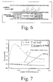
- FIG. 6 schematically illustrates a cross-section of a reactor with adjacent partial boiling heat exchange.
- FIG. 9 shows thermocouple placement in the test reactors.
- FIG. 10 shows the effect of temperature on the performance of Catalyst 1 at 90 psig and 580 ms contact time with a high C2:Acid:O2 ratio.
- FIG. 11 shows the effect of temperature on the performance of Catalyst 1 at low pressure (6 psig) and long contact time (580 ms). O 2 was fed as air.
- FIG. 12 shows the performance of Catalyst 1 as a function of contact time (1/space velocity) at 140 C and 95 psig with a 6:3:1 C2:Acid:O2 feed. O2 was fed as air.
- FIG. 13 shows the performance of Catalyst 1 as a function of contact time (1/space velocity) at 150° C. and 91 psig with a 6:3:1 C2:Acid:O2 feed. O2 was fed as air.
- FIG. 14 shows the effect of contact time on catalyst performance at fast flow rates.
- FIG. 15 shows the effect of varying C2/O2 ratio on performance of Catalyst 2 at two different contact times.
- the invention can provide increased capacity per unit by increasing the number of repeating units per reactor unit.
- a repeating unit comprises a reaction channel in thermal contact with a heat exchanger; and could be, for example, a layer of reaction channels in thermal contact with a layer of heat exchange channels. Repeating units can be stacked to increase capacity. In a shell and tube configuration, the repeating unit is a single tube.
- the number of repeating units connected together is preferably three or more, in some embodiments three to one thousand, and in some embodiments at least one hundred.
- a heat exchanger preferably one or more coolant channels, preferably coolant microchannels
- the process can be run in known apparatus, preferably microchannel apparatus such as apparatus in which layers of process channels (preferably at least 3) alternate with layers of coolant channels (preferably at least 4).
- 3 alternating, interleaved layers would comprise layers in the order coolant: reaction: coolant: reaction: coolant: reaction.
- flow into and/or out of some or all of a plurality of coolant and/or endothermic reaction channels passes through a manifold or manifolds that combines or distributes the fluid flow.
- microchannels are arranged in parallel arrays of planar microchannels; preferably a layer comprising a parallel array of planar microchannels is adjacent with another layer comprising a parallel array of planar microchannels where the adjacent layers exchange heat.
- the height and/or width of a reaction channel is preferably 17 mm or less, preferably 10 mm or less, preferably 5 mm or less, and more preferably 2 mm or less, and in some embodiments 50 to 1000 ⁇ m, and in some embodiments 0.05 to 2 mm.
- a reaction channel is regular or irregular in shape, and during operation, wherein one or more of such mass transfer, heat transfer and/or a chemical processing operation (or operations) occurs, at least in significant part, as fluid flows through fixed channels having surface-to-volume ratios of 10 or more square centimeters of channel internal surface area per cubic centimeter of channel internal volume; for the purposes of this definition, surface area and volume are determined on the basis of nominal internal channel dimensions, exclusive of surface area enhancers such as catalysts or catalyst supports in or on the walls of such channels. Height and width of a channel are perpendicular to the direction of flow.
- the portion of a reaction channel that contains a reaction zone or zones is less than 2 meters, more preferably less than 1 meter, and still more preferably less than 0.5 meter in length.
- the catalyst can fill up a cross-section of a reaction (for VAM) and/or endothermic reaction channel (a flow-through catalyst) or only occupy a portion of the cross-section of a reaction channel (flow-by).
- a flow-by catalyst configuration can create an advantageous capacity/pressure drop relationship.
- gas preferably flows in a 0.1-2.0 mm gap adjacent to a catalyst insert or a thin layer of catalyst that contacts a microchannel wall (preferably a microchannel wall that contacts the catalyst is in direct thermal contact with a coolant channel).
- bulk flow path refers to an open path (contiguous bulk flow region) within a reaction chamber. A contiguous bulk flow region allows rapid gas flow through a reaction chamber without large pressure drops.
- Bulk flow regions within each reaction channel preferably have a cross-sectional area of 5 ⁇ 10 ⁇ 8 to 1 ⁇ 10 ⁇ 2 m 2 , more preferably 5 ⁇ 10 ⁇ 7 to 1 ⁇ 10 ⁇ 4 m 2 .
- the bulk flow regions preferably comprise at least 5%, more preferably 30-80% of either 1) the internal volume of a reaction channel, or 2) a cross-section of a reaction channel.
- a static mixer is disposed at an inlet to a reaction channel.
- FIGS. 1A and 1B schematically illustrate tubular reactors 6 and 8 .
- the reactors can contain sealed sections 10 , 11 that are pressurized with a reactant (such as O 2 ).
- the porous sections are preferably sections of sintered metal along the length of metal tubes 4 .
- FIG. 1A illustrates only one pressurized, sealed section 10 , there are preferably plural such sections, such as at least 2 or at least 10.
- FIG. 1B shows an embodiment with a porous section near the connection 12 .
- Microchannel apparatus can be made by known processes and can be made by processes such as stamping, partial etching, and spot welding features to backings. To make hermetic seals between layers in the reactor, diffusion bonding, braising and/or seam welding can be used.
- Full scale reactors can be designed to be disassembled and repeating sub-assemblies can be separated from one another.
- the units may be gasketed together or seam welded. In the latter case, the perimeter weld would need to be removed to disassemble the unit.
- the use of repeating subassemblies is an advantageous design feature because it allows for the catalyst containing reactor sections to be refurbished as simple, discrete units without having to make special accommodations for the staging sub-assemblies. This feature also aids in the cleaning and maintenance of the entire full scale reactor.
- Multiple assemblies can be linked together in parallel to increase plant capacity.
- Sub-assemblies can use: orifice plates, foam, membrane material, etc. to redistribute product from a first subassembly that is then added to a second subassembly.
- Each of the subassemblies may be fabricated by the same or different methods.
- Vinyl acetate can be produced in stainless steel reactors, with or without barrier coatings to protect reaction channel walls. If barrier coating or coatings are used, they may be deposited by physical or chemical vapor deposition, or from solution or wash coating. In some embodiments, a barrier coating is selected from alumina, titania, silica, and combinations thereof. In one embodiment, material protection is provided by directly depositing a layer of alumina from a gas containing hydrogen, water, hydrogen chloride and aluminum trichloride. Wall coatings can protect reactor walls, but they can also be useful for adhering catalyst wall coatings.
- the invention can employ any of the catalyst compositions known for the production of VAM.
- Suitable catalysts (and methods for making the catalysts) for catalyzing the production of VAM are well-known. Examples of catalysts for the production of VAM are described, for example, in U.S. Pat. Nos. 3,743,607, 3,775,342, 5,557,014, 5,990,344, 5,998,659, 6,022,823, 6,057,260, and 6,472,556; all of which are incorporated herein by reference.
- Preferred catalysts comprise Pd, Au, and, in some embodiments potassium acetate (KOAc).
- the catalysts also preferably contain a refractory support, preferably a metal oxide such as silica, silica-alumina, titania or zirconia, more preferably zirconia.
- the catalyst (preferably a catalyst layer) preferably comprises more than 2 weight % Pd, more preferably at least 4 wt % Pd; in some embodiments greater than 10 wt % Pd, and in some embodiments at least 12 wt % Pd.
- this weight percent refers to the entire layer or rim that contains a substantial amount of catalyst (i.e., catalyst that will have a significant impact on reactivity); it is not an arbitrarily selected portion of a thin layer or rim.
- One process for making Pd/Au catalysts typically includes the steps of impregnating the support with aqueous solutions of water-soluble salts of palladium and gold; reacting the impregnated water-soluble salts with an appropriate alkaline compound e.g., sodium hydroxide, to precipitate (often called fixing) the metallic elements as water-insoluble compounds, e.g. the hydroxides; washing the fixed support material to remove un-fixed compounds and to otherwise cleanse the catalyst of any potential poisons, e.g. chloride; reducing the water insoluble compounds with a typical reductant such as hydrogen, ethylene or hydrazine, and adding an alkali metal compound such as potassium or sodium acetate.
- an appropriate alkaline compound e.g., sodium hydroxide
- Preferred catalysts are of the rim or thin layer type in which the active metals are distributed in a thin rim or thin layer of material; thicker layers of active metals produce a higher proportion of undesirable side products.
- the rim or thin layer typically has a thickness of 50 to 1000 micrometers ( ⁇ m), preferably 400 ⁇ m, more preferably in the range of 50 to 200 ⁇ m. For small catalyst particles having thicknesses less than these values, for example 1000 ⁇ m or less, active metals can be dispersed throughout the particles.
- the catalyst has a graded activity from one end of a reaction zone (or one end of a reaction channel) to the other end of the reaction zone (or other end of the reaction channel) such that the catalyst activity increases along the length of a zone or channel. In this fashion, the reaction can be moderated so that heat is generated more equally along the length of the zone or channel.
- compositions can take conventional forms such as powders and pellets, or can be deposited on a large pore support.
- suitable catalyst supports include felt (nonwoven fibers), foam, fin, screen mesh, gauze, honeycomb, or other porous structure.
- the catalyst is a catalytic wall coating (typically a washcoat) applied onto a channel wall or walls.
- the flow of reactants may be through the catalyst, as is typical in the case of a powder, foam, felt or gauze.
- the flow of reactants may also be around or ‘by’ a catalyst, such as by a wall coating, fin (i.e., catalyst coated on a fin or fins), or screen mesh disposed adjacent to a heat transfer wall (leaving a bulk flow path adjacent to the catalyst).
- the highest number of catalyst sites per unit volume is envisioned for a powder catalyst or other flow-through structure such as a microporous packed bed of pellets or a foam.
- the corresponding pressure drop per unit length will also be highest for the flow through structures.
- the expected pressure drop per length for a powder catalyst ranges between 0.1 atm/m to 10 atm/m depending upon the size of particles, their shape, corresponding void volumes for flow and operating temperature and pressure of the reactor zone.
- a catalyst is intermittently disposed in a process channel for inter-stage mixing of reactants and/or liquid or gaseous catalyst life extenders, including air, oxygen, ethylene, acetic acid, or potassium acetate.
- orifices are disposed in between catalyst zones so that there is mixing but no, or substantially no, catalyzed reaction in regions between catalyst-containing zones. An example of this is schematically illustrated in FIG. 2A in which a catalyst 22 is disposed between mixing zones 24 .
- a reactor of the present invention comprises at least 10 cubic centimeters (cc), more preferably at least 20, and still more preferably at least 100 cc of solid catalyst (preferably in the form of a fixed bed). This amount of catalyst can be in a single channel but this much or more can be dispersed over plural reaction zones in plural reaction channels.
- the process for the production of vinyl acetate has a ratio of ethylene to oxygen in the reactor of 6:1 or less throughout a reaction zone; more preferably 4:1 or less throughout a reaction zone; and still more preferably 2.5:1 or less throughout a reaction zone.
- the process for the production of vinyl acetate has a ratio of acetic acid to oxygen of 6:1 or less throughout a reaction zone; more preferably a ratio of 4:1 or less throughout a reaction zone; and more preferably a ratio of 2.5:1 or less throughout a reaction zone.
- the relative amounts of reactants are in the range of ethylene:acetic acid:dioxygen of 6:3:1 and 2:2:1.
- the O 2 concentration in a reaction channel is at least 8%, in some embodiments at least 16%, and in some embodiments in the range of 9 to 20% (by mol).
- the ratio of gaseous recycle to fresh feed is less than 10:1, more preferably 6:1 or less, still more preferably 2:1 or less, more preferably 1:1 or less, and most preferably 0.5:1 or less.
- a reactant is staged through plural (preferably at least 3) openings into a reaction channel. See, for example, FIG. 2A .
- Any combination of ethylene, oxygen or acetic acid can be staged into the process channel.
- acetic acid or a mixture of acetic acid and oxygen can be added through plural orifices along the length of a process channel containing a catalyst and flowing ethylene.
- Staging of a reactant or reactants can provide improved temperature control. Tight temperature range in reactors helps maintain high product selectivity and increase the catalyst lifespan. For the case of no staging, all reactants are premixed and fed into the inlet of the reactor. The maximum temperature is observed at a certain location which is determined by the reaction rate and the heat transfer feature of the catalyst bed as exemplified by the dashed curve in FIG. 2B .
- the solid curve is the temperature profile for an equal bed size, overall feed rate and temperature but with three distinct feed locations within the reactor bed. Staging can reduce the temperature rise within a reactor as compared to the temperature rise for a pre-mixed feed.
- Staging also provides another means of controlling the rates of reactions in the reactor zone.
- concentration of the reactants is at a maximum at the reactor inlet. Due to the high concentration of feeds, the reaction rates are increased. This depletes the reactants, such that the concentrations of feed components decrease rapidly and the reaction rate is slowed.
- the overall reaction rate is the average of the incremental rates throughout the reaction zone, but the majority of the reaction occurs early on in the zone.
- the reaction rates can be moderated at the inlet and increased further down the reaction zone. This allows more effective use of all of the catalyst, while avoiding having excessive reaction occur over any particular portion of the reaction zone.
- staging occurs by injecting one or more reactants through plural openings in a continuous process channel.
- reactants may alternatively, or additionally, be added into manifold regions (headers or footers) that connect plural channels.
- the mixing areas adjacent the injection points (orifices) do not contain catalyst.
- a continuous process channel has catalyst-free mixing zones alternating with catalyst-containing reaction zones (such as at least 2 mixing zones alternating with at least 2 reaction zones).
- a “continuous” channel is a channel that does not flow into a manifold and back into the channel.
- FIG. 3 A preferred configuration for making vinyl acetate is schematically illustrated in FIG. 3 .
- This configuration includes two repeated sub-assemblies.
- the first such sub-assembly can be described as the reactor section and thus has housed within it all of the catalyst needed to perform the VAM reaction.
- the second sub-assembly can be described as the staging section and thus has oxygen and/or other streams injected/mixed into the main reactant stream.
- This configuration allows for these sub-assemblies to be alternated such that a full scale reactor is constructed consisting of multiple reactor sub-assemblies separated by staging sub-assemblies. This allows for oxygen and/or other streams to be mixed into the main reactant stream immediately prior to and/or immediately following the catalyst sections of the reactor.
- the reactor section sub-assembly can be greatly simplified due to the absence of mixing geometry and allows for the inclusion of heat exchange channels that can be located on both sides of any/all of the reactant channels.
- the staging section sub-assembly can be simplified due to the absence of any catalyst channels and can therefore be designed to allow for multiple streams to be simultaneously mixed.
- FIG. 3 shows two such streams (O2 & acetic acid) being mixed into the reactant stream in stages and it should be understood that many different streams can be mixed together with the reactant stream in a similar configuration.
- the reaction kinetics and reaction heat can be considered to determine the number of feed points and locations.
- the flow rate through each of opening is controlled by the size and shape of the orifice. Mixing efficiency can also be considered in selecting the orifice shape.
- the length of the empty channel section near each injection point is at least about 8 times the hydraulic diameter of the channel—preferably, approximately the characteristic mixing length in micro-channels. Since the gap size is small in microchannels, the total mixing length is a modest value compared to the overall channel length dimensions.
- the acetic acid partial pressure can be kept high to push the reaction rate forward while keeping its partial pressure low enough to avoid condensation in the reactor. As acetic acid is consumed, distribution points keep the partial pressure high.
- liquid acetic acid would be deleterious to the results and could destroy the activity of the catalyst.
- the acetic acid is converted as it goes, and more is fed such that the total fed exceeds that corresponding to the dew point pressure; however, the acetic acid does not actually condense in the reaction zone because the partial pressure of acetic acid remains below the dew point at all points along the reaction channel.
- staged addition is preferred; it is believed that a process channel could operate without staging, but instead having a flow of liquid acetic acid into a reaction zone that is separated from the catalyst, preferably by a vapor permeable membrane.
- any and all of the reactants have short contact times in the reaction zone.
- ethylene can have a contact time of 500 ms or less in a reaction zone or zones; or oxygen can have a contact time of 500 ms or less, or a mixture of ethylene and acetic acid have a contact time of 500 ms or less in a reaction zone, etc.
- the contact times are much less than in conventional reactors.
- the speed of the reaction can also be described in terms of linear velocity and/or space velocity.
- linear velocity (or mass flow rate) of the gas through the reaction zone is greater at the outlet of the reaction zone than it is at the inlet to the reaction zone (e.g., because some oxygen is added to the feed in a staged manner along the reactor length).
- the feed streams consist only of acetic acid, ethylene and dioxygen.
- other components may also be present, for example, diluents such as nitrogen, water vapor, and carbon dioxide.
- diluents such as nitrogen, water vapor, and carbon dioxide.
- other gases that are essentially inert to the reaction conditions may also be employed.
- the oxygen-containing stream contains less than 90% O 2 . In some embodiments, air is used as the oxygen supply.
- Total pressure (which can be defined either at the inlet, the outlet or both, or averaged throughout a reaction channel) is, in some embodiments, in the range of 1 to 20 bar, in some embodiments in the range of 5 to 15 bar.
- Temperature in reaction zone is preferably at least 130° C., in some embodiments in the range of 120 to 400° C., in some embodiments 140-200° C., and in some embodiments 150-180° C.
- temperature (measured by thermocouples at (or in) the reaction channel walls) over at least 50% of the length of a reaction channel (or at least 50% of the length of a reaction zone) varies by less than 10° C., more preferably 5° C. or less; this is in contrast with conventional reactors that typically have hot spots that are 10° C. to 15° C. higher than the average temperature of the catalyst bed.
- temperature over at least 50% of the length of a cooling channel (adjacent to a reaction channel) varies by less than 10° C., more preferably 5° C. or less.
- FIG. 4 schematically illustrates a section of a microchannel matrix repeating unit, with co-current coolant and process reaction flow.
- FIG. 5 a and FIG. 5 b show that under certain operating conditions single phase convective heat transfer is sufficient to remove the reaction heat in a micro configuration. The reason is the available heat transfer surface area per unit reactor volume is much greater in micro-channel reactors than that in a conventional packed-bed reactor. If single phase convective heat transfer and surface area are sufficient to remove the reaction heat, several parameters should be used to optimize the heat removal in the heat exchange channels.
- the cooling flow rate can be increased to enhance the heat removal capability.
- the cooling channel gap is another parameter for design toward the desired heat removal capability. Decreasing the hydraulic diameter of the channel helps increase the convective heat transfer coefficient.
- the inventive processes may also be characterized by per pass conversion of reactants and per pass selectivities to products.
- per pass it is meant on a single traverse of a reaction channel (or in some embodiments through a reaction zone) without recycling.
- inventive methods can (and often will) be operated with a recycle step; however, a unique and unexpected aspect of invention is its high conversions coupled with excellent product selectivity that are obtained without a recycle step.
- the invention can be characterized by selected conversions and/or selectivites either individually or in any combination.
- Per pass conversion of dioxygen is preferably at least 30%, more preferably 60%, still more preferably at least 80%, and yet more preferably at least 90%; in some embodiments 20-60%, in some embodiments 55-95%, and in some embodiments 50-75%.
- Per pass conversion of ethylene is preferably at least 20%, more preferably at least 30%, and in some embodiments about 25 to about 35%.
- Selectivity to carbon dioxide is preferably less than 15% (based on how much of the ethylene is converted to carbon dioxide), more preferably less than 10%, and in some embodiments about 5 to 10%.
- the conversion and selectivity properties of the invention can also be derived from the data presented in the Examples section below.
- Partial boiling heat transfer can be applied to vinyl acetate monomer (VAM) production in micro-channels.
- a calculated example is based on microchannels made with a combination of plates having cross-sectional dimension 0.020 inch thickness ⁇ 0.5 inch width ⁇ 3 inch length. The gap on the reaction side is 0.04 inch and on the coolant side is 0.04 inch. On the reaction side, a mixture of ethylene (C2H4), acid gas (CH3COOH) and oxygen (O2) are fed at temperature 160° C. and pressure 8 atm. The micro-channel is packed with micro-pellet catalyst with the void fraction around 0.4.
- a schematic cross-sectional illustration of a reactor with adjacent partial boiling heat exchange is shown in FIG. 6 .
- the VAM producing reaction release heat into the packed bed and then the heat conducts through the channel walls to the surface on the coolant side, where the coolant vaporizes.
- the coolant used in this calculated example is water.
- the reactants are at the highest concentration level and the reaction rate is at the maximum. This leads to the asymmetrical temperature profile along the catalyst bed. Accordingly, the heat flux profile on the channel wall has the temperature peak near the inlet of the reactor.
- a temperature hot spot near the beginning of the catalyst bed is detrimental to the selectivity of the desired product—VAM and the product yield. Also, the catalyst lift time will be shortened due to the high temperature. It is desirable to operate the VAM reactor at the iso-thermal condition, or temperature variation along the reaction path within a tight range.
- FIG. 7 temperature profiles along the reactor length using various heat removal schemes are compared. It shows that the temperature variation along the reactor length is much tighter when partial boiling is applied to remove the heat. Another advantage of applying partial boiling heat removal is that highly active catalyst can be used to give temperature profiles without large spikes.
- FIG. 8 shows the temperature profiles along the centerline of the catalyst bed calculated under four contact time levels with single phase heat convection as the heat removal method.
- the gap size of the coolant channel is 0.04 inch.
- the wall thickness is 0.02 inch and the channel gap on the process side is 0.04 inch also.
- the coolant flow stream has the average velocity of 0.3 m/s. Under lower contact time, or larger throughput, the temperature rise in the catalyst bed is larger. At 250 ms contact time on the process side, if partial boiling is the choice of heat removal method, the temperature rise in the catalyst bed is less than 10° C.
- staging of reactants can be an effective technique to avoid hot spots and effectively manage temperature.
- the invention requires distributing at least one reactant from one channel into a second adjoining channel where a reaction is taking place.
- the distribution of the fluids from macro scale fluid channels to the unit's microchannels should be designed to achieve the desired flow distribution.
- one reactant stream uses a large macro scale manifold to connect a relatively larger stream to relatively smaller, multiple, parallel microchannels.
- the direction of an inlet flow in a macro scale manifold can be aligned parallel, perpendicular or some intermediate angle with regard to the direction of the connecting channels (connecting channels may connect a header to a footer).
- one or more reactant streams uses a macro-to-micro (M2M) manifold for distribution within a microchannel unit.
- M2M macro-to-micro
- Quality Index factor “Q 1 ” is a measure of how effective a manifold is in distributing flow. It is the ratio of the difference between the maximum and minimum rate of connecting channel flow divided by the maximum rate. For systems of connecting channels with constant channel dimensions it is often desired to achieve equal mass flow rate per channel. The equation for this case is shown below, and is defined as Q 1 .
- Q 1 m max - m min m max ⁇ 100 ⁇ %
- m max [kg/sec] maximum connecting channel mass flow rate
- m min [kg/sec] minimum connecting channel mass flow rate
- Q 2 G max - G min G max ⁇ 100 ⁇ % , where G is the mass flux rate.
- G the mass flux rate.
- Q 1 and Q 2 are defined based on the channels that comprise 95% of the net flow through the connecting channels, the lowest flow channels are not counted if the flow through those channels is not needed to account for 95% of the net flow through the connecting channels.
- a device was designed that included an internal mixing zone and facility to monitor the reactor wall temperature at 10 different locations.
- the device was also fitted with means for introducing a heat transfer fluid along the length of the reaction zone in a parallel channel.
- the reactors were constructed with rectangular catalyst zones of 1.5 inches long by 0.5 inches wide by 0.04 inches tall and 1.5 inches long by 0.5 inches wide by 0.08 inches tall (volumes 0.492 and 0.983 cc), referred to as a “40-gap” and “80-gap” reactor, respectively.
- a 40-gap 1.5 inches long by 0.5 inches wide by 0.04 inches tall and 1.5 inches long by 0.5 inches wide by 0.08 inches tall
- volumes 0.492 and 0.983 cc volumes 0.492 and 0.983 cc
- the reactors can be run under nearly isothermal conditions with high heat generation and removal.
- Typical temperature profiles of the wall along the catalyst bed show temperature gradients of 1° C. or less.
- the catalyst test system consists of vaporizer/preheater to preheat the reactants, a reactor temperature controlled by a recirculating oil bath, a microchannel heat exchanger to cool the products and a dual chilled vapor liquid separator system.
- the reactor was supported in a vertical position, and was packed with foam and quartz wool to hold the catalyst in place, and enough catalyst to fill 1.0 inch of reactor length. Upstream of the catalyst a small portion of the catalyst support impregnated with potassium acetate was packed into the channel.
- Catalysts 1 and 2 were prepared by crushing and sieving commercially available silica alumina particles (Catalyst 1) or zirconia (Catalyst 2) to give particles in the range of 80 to 140 microns
- the Pd (43.2 g/l of catalyst in the form of Pd(NH 3 ) 4 (OH) 2 was added as an aqueous solution to the support using the incipient wetness method, the Pd-contaning support was dried at 110° C. for 5 h and then calcined in air at 350° C. for 2 h.
- Sufficient KAuO 2 solution was added to give an Au loading of 28.0 g/l of catalyst is dried at 110 C.
- the reactor was charged with 1.2 cc of the catalyst and a charge of 0.3 cc of silica impregnated with 40 g per liter of KOAc in the region immediately before the catalyst.
- the catalyst is held in place by a small piece of FeCrAlY foam and quartz wool.
- thermocouples placed in the connecting tubes to the reactor system approximately 2 to 5 cm from the inlet or outlet of the reactor. Pressure transducers were added to each of the inlet and outlet streams at similar locations. Thermocouples were also installed in thermocouple ports on the outer surface of the reactor system along the length of the mixer and reactor sections.
- Pressure transducers were calibrated using a Fluke pressure calibrator model 7181006 with a Fluke 700P07 or 700P06 pressure module which were calibrated and certified by Fluke.
- the TCD gas chromatograph was calibrated against calibration gases blended and certified by Praxair Distribution Inc.
- the FID gas chromatograph was calibrated with an in-house mixed solution which was measured by volume, and double checked by mass.
- the reactor system was pressure tested by applying a static pressure of ⁇ 150 psig using nitrogen fluid. If the leak rate did not exceed 0.5 psig in 15 minutes, then the reactor system was considered ready for operation.
- the system was pressurized to the run plan operating pressure at ⁇ 5-8 psig/min.
- the reactor was then heated at 5° C./min to the run plan operating temperature by the flow of hot oil, and the inlet and outlet lines of the catalyst test system are heating using electrical heating tape to a minimum of 140° C. to prevent acetic acid condensation.
- the gaseous reactants typically ethylene and nitrogen, were preheated concurrently with the vaporization of acetic acid to 170-200° C.
- the vaporizer/preheater was a 3 ⁇ 8′′ 316 stainless steel tube wrapped in a 4 foot, 312W electrical resistance heat tape. Control of the heat tape was achieved using an Omega controller.
- the oxygen or air reactant was not preheated prior to entrance into the reactor.
- the main system knockout drum was then set and operated at 8° C., while the final knockout drum was operated at ⁇ 10.5° C. Then the reactant flows were initiated. Ethylene was slowly turned up to the run plan flowrate while the process side nitrogen was adjusted to the tracer flowrate. Then acetic acid was initiated to the run plan flowrate. After the system was stable at the proper temperature and pressure, oxygen was slowly turned on while the oxygen side nitrogen was slowly turned off.
- FIG. 11 presents the results of these tests.
- the conversion of oxygen and the selectivity to CO2 were inferior to the high pressure tests, with a maximum O2 conversion of only 36% and the CO2 selectivity always above 20%.
- FIGS. 12 and 13 present results of the dependence of catalyst performance on contact time for Catalyst 1.
- the feed in these experiments was a 6:3:1 mixture of ethylene, acetic acid and oxygen, with the oxygen fed as air.
- the maximum oxygen conversion was 61% with a 12.5% CO 2 selectivity when the contact time was 689 ms.
- the oxygen conversion was lower and the CO 2 selectivity was lower.
- FIG. 15 summarizes the results of the performance of this catalyst as a function of the ethylene/oxygen ratio at two different contact times.
- the oxygen conversion reached as much as 77% at the longer contact time (440 ms) with a 6/3/1 ethylene/acid/oxygen feed. Under these conditions the CO 2 selectivity was only 7.2%.
- FIGS. 10-15 show that the increase in oxygen conversion is more rapid (larger slope) than the increase in selectivity to carbon dioxide when utilizing the system according to the invention.
- the results demonstrate superior results over a wide range of reaction conditions. This result is surprising in light of the prior art.
- U.S. Pat. No. 6,022,823 described experiments conducted in a 1 inch outer diameter tubular reactor containing 30 ml of catalyst with a bed height of 3 inches. This configuration has a high heat transfer surface area to reaction zone volume of 1.78 cm ⁇ 1 .
- Data provided for the reactions in that reactor show that, while it is possible to achieve high levels of oxygen conversion, the selectivity to VA is low. Further, their data shows that the selectivity to VA decreases dramatically as the oxygen conversion is increased.
- Tables 1 and 2 provide further examples of results obtained that demonstrate the effectiveness of the invention in achieving high conversion of oxygen, ethylene and/or acetic acid while simultaneously achieving high selectivity to VA, here measured as low selectivity to CO2.
Abstract
Description
C2H4+CH3COOH+0.5 O2→CH3COOCH═CH2+H2O
The reaction takes place commercially in liquid phase using palladium/copper salts as homogeneous catalysts or in the gas phase over heterogeneous catalysts containing palladium. The reaction occurs at temperatures above 140° C. and at pressures of 0.5 to 50 atm. Byproducts are water, CO2 and small quantities of ethyl acetate, ethylidene diacetate, and glycol acetates. The reaction is exothermic (−178 kJ/gm-mole).
where
mmax [kg/sec]=maximum connecting channel mass flow rate
mmin [kg/sec]=minimum connecting channel mass flow rate
For cases when there are varying connecting channel dimensions it is often desired that the residence time, contact time, velocity or mass flux rate have minimal variation from channel to channel such that the required duty of the unit operation is attained. For those cases we define a quality index factor Q2:
where G is the mass flux rate. For cases when all the connecting channels have the same cross sectional area, the equation for Q2 simplifies to Q1. The quality index factor gives the range of connecting channel flow rates, with 0% being perfect distribution, 100% showing stagnation (no flow) in at least one channel, and values of over 100% indicating backflow (flow in reverse of the desired flow direction) in at least one channel. In this invention, Q1 and Q2 are defined based on the channels that comprise 95% of the net flow through the connecting channels, the lowest flow channels are not counted if the flow through those channels is not needed to account for 95% of the net flow through the connecting channels. By selection of appropriate M2M designs for microchannel reactors, quality index factors for reactant flows can be below 20%. See Fitzgerald et al., U.S. patent application Ser. No. 10/695,400, now U.S. Pat. No. 7,422,910, incorporated herein by reference.
| TABLE 1 | ||||
| |
|
|
||
| ethylene | sccm | 21.2 | 21.2 | 21.2 |
| acetic acid | sccm | 11.8 | 11.8 | 11.8 |
| oxygen | sccm | 3.5 | 3.5 | 3.5 |
| nitrogen tracer | sccm | 3.9 | 3.9 | 3.9 |
| Inlet Pressure | (psig) | 55.92 | 52.6 | 53.2 |
| Pressure Drop | (psi) | 55.7 | 52.2 | 53.0 |
| Contact Time | (ms) | 1487 | 1487 | 1487 |
| Ethylene Conversion | (%) | 16.8% | 14.1% | 5.8% |
| Ethylene selectivity | (%) | 2.6% | 11.3% | 17.0% |
| to CO2 | ||||
| Oxygen Conversion | (%) | 93.3% | 83.7% | 97.4% |
| Oxygen selectivity to | (%) | 2.8% | 11.6% | 6.1% |
| CO2 | ||||
| O2 conversion to CO2 | (%) | 2.7% | 9.8% | 6.1% |
| Bed avg temperature | (C.) | 128 | 138 | 150 |
| C2H4:O2 | (mol/mol) | 6.06 | 6.06 | 6.06 |
| CH3COOH:O2 | (mol/mol) | 3.36 | 3.36 | 3.36 |
| HOAc Conversion | (%) | 29.5% | 22.6% | 8.7% |
| TABLE 2 | |||||
| Nitrogen | |||||
| CH3COOH: | Tracer | ||||
| Contact | C2H4:O2 | O2 | Bed avg | (N2) | |
| Catalyst | Time (ms) | (mol/mol) | (mol/mol) | temp (C.) | (sccm) |
| 1 | 425 | 5.21 | 3.34 | 150 | 22.23 |
| 1 | 346 | 3.81 | 2.46 | 150 | 24.20 |
| 1 | 346 | 3.81 | 2.46 | 150 | 24.20 |
| 1 | 346 | 3.81 | 2.46 | 150 | 24.20 |
| 1 | 279 | 7.13 | 4.54 | 164 | 32.50 |
| 1 | 346 | 3.81 | 2.46 | 150 | 24.20 |
| 1 | 346 | 3.81 | 2.46 | 150 | 24.20 |
| 1 | 346 | 3.81 | 2.46 | 150 | 24.20 |
| 1 | 425 | 5.21 | 3.34 | 151 | 22.23 |
| 1 | 425 | 5.21 | 3.34 | 151 | 22.23 |
| 1 | 425 | 5.21 | 3.34 | 151 | 22.23 |
| 1 | 425 | 5.21 | 3.34 | 151 | 22.23 |
| 1 | 425 | 5.21 | 3.34 | 151 | 22.23 |
| 1 | 425 | 5.21 | 3.34 | 151 | 22.23 |
| 2 | 444 | 6.00 | 3.32 | 140 | 6.6 |
| 2 | 409 | 5.00 | 3.27 | 140 | 6.6 |
| Oxygen | Ethylene | HOAc | Ethylene | Oxygen |
| Conversion | Conversion | Conversion | selectivity | selectivity |
| (%) | (%) | (%) | to CO2 (%) | to CO2 (%) |
| 79.3% | 31.7% | 75.2% | 8.1% | 33.7% |
| 79.0% | 37.8% | 55.1% | 5.8% | 21.2% |
| 79.3% | 32.6% | 47.0% | 7.0% | 21.9% |
| 76.8% | 35.9% | 52.5% | 5.6% | 20.1% |
| 88.2% | 25.0% | 61.1% | 5.6% | 22.8% |
| 80.7% | 38.2% | 55.7% | 5.8% | 21.0% |
| 80.1% | 37.9% | 55.2% | 6.0% | 21.5% |
| 80.3% | 34.2% | 49.7% | 6.2% | 20.2% |
| 82.4% | 31.8% | 76.0% | 7.5% | 30.2% |
| 82.6% | 32.0% | 76.2% | 7.8% | 31.5% |
| 82.4% | 32.1% | 76.4% | 7.8% | 31.7% |
| 82.4% | 30.3% | 71.9% | 8.1% | 31.2% |
| 81.2% | 31.7% | 75.6% | 7.7% | 31.4% |
| 82.0% | 32.0% | 76.1% | 7.9% | 32.0% |
| 76.6% | 33.0% | 44.7% | 7.2% | 18.7% |
| 61.0% | 30.2% | 57.4% | 7.9% | 19.6% |
Claims (85)
Priority Applications (8)
| Application Number | Priority Date | Filing Date | Title |
|---|---|---|---|
| US11/256,217 US7468455B2 (en) | 2004-11-03 | 2005-10-20 | Process and apparatus for improved methods for making vinyl acetate monomer (VAM) |
| EP15003523.6A EP3025777A1 (en) | 2004-11-03 | 2005-11-02 | Apparatus for the production of vinyl acetate monomer (vam) |
| PCT/US2005/039714 WO2006052615A1 (en) | 2004-11-03 | 2005-11-02 | Process and apparatus for improved methods for making vinyl acetate monomer (vam) |
| MX2007005285A MX2007005285A (en) | 2004-11-03 | 2005-11-02 | Process and apparatus for improved methods for making vinyl acetate monomer (vam). |
| CN2005800378245A CN101084182B (en) | 2004-11-03 | 2005-11-02 | Process and apparatus for improved methods for making vinyl acetate monomer (vam) |
| EP05847767A EP1812373A1 (en) | 2004-11-03 | 2005-11-02 | Process and apparatus for improved methods for making vinyl acetate monomer (vam) |
| TW094138497A TWI399244B (en) | 2004-11-03 | 2005-11-03 | Process and apparatus for improved methods for making vinyl acetate monomer (vam) |
| US12/272,804 US8029748B2 (en) | 2004-11-03 | 2008-11-18 | Process and apparatus for improved methods for making vinyl acetate monomer (VAM) |
Applications Claiming Priority (2)
| Application Number | Priority Date | Filing Date | Title |
|---|---|---|---|
| US62484604P | 2004-11-03 | 2004-11-03 | |
| US11/256,217 US7468455B2 (en) | 2004-11-03 | 2005-10-20 | Process and apparatus for improved methods for making vinyl acetate monomer (VAM) |
Related Child Applications (1)
| Application Number | Title | Priority Date | Filing Date |
|---|---|---|---|
| US12/272,804 Continuation US8029748B2 (en) | 2004-11-03 | 2008-11-18 | Process and apparatus for improved methods for making vinyl acetate monomer (VAM) |
Publications (2)
| Publication Number | Publication Date |
|---|---|
| US20060116528A1 US20060116528A1 (en) | 2006-06-01 |
| US7468455B2 true US7468455B2 (en) | 2008-12-23 |
Family
ID=36096400
Family Applications (2)
| Application Number | Title | Priority Date | Filing Date |
|---|---|---|---|
| US11/256,217 Expired - Fee Related US7468455B2 (en) | 2004-11-03 | 2005-10-20 | Process and apparatus for improved methods for making vinyl acetate monomer (VAM) |
| US12/272,804 Expired - Fee Related US8029748B2 (en) | 2004-11-03 | 2008-11-18 | Process and apparatus for improved methods for making vinyl acetate monomer (VAM) |
Family Applications After (1)
| Application Number | Title | Priority Date | Filing Date |
|---|---|---|---|
| US12/272,804 Expired - Fee Related US8029748B2 (en) | 2004-11-03 | 2008-11-18 | Process and apparatus for improved methods for making vinyl acetate monomer (VAM) |
Country Status (6)
| Country | Link |
|---|---|
| US (2) | US7468455B2 (en) |
| EP (2) | EP3025777A1 (en) |
| CN (1) | CN101084182B (en) |
| MX (1) | MX2007005285A (en) |
| TW (1) | TWI399244B (en) |
| WO (1) | WO2006052615A1 (en) |
Cited By (11)
| Publication number | Priority date | Publication date | Assignee | Title |
|---|---|---|---|---|
| US20090054683A1 (en) * | 2004-10-15 | 2009-02-26 | Karsten Bueker | Reactor and method for synthesising vinyl acetate in the gaseous phase |
| US20110166010A1 (en) * | 2007-05-31 | 2011-07-07 | Sud-Chemie Ag | PD/AU SHELL CATALYST CONTAINING Hf02, PROCESSES FOR THE PREPARATION AND USE THEREOF |
| WO2013081883A1 (en) | 2011-11-28 | 2013-06-06 | Celanese International Corporation | Integrated process for producing polyvinyl alcohol or a copolymer thereof and ethanol |
| US8586780B2 (en) | 2007-05-31 | 2013-11-19 | Sued-Chemie Ip Gmbh & Co. Kg | Doped Pd/Au shell catalyst, method for producing the same and use thereof |
| US8697802B2 (en) | 2011-11-28 | 2014-04-15 | Celanese International Corporation | Process for producing polyvinyl alcohol or a copolymer thereof |
| US8927452B2 (en) | 2007-05-31 | 2015-01-06 | Sud-Chemie Ag | Method for producing a shell catalyst and corresponding shell catalyst |
| US9617187B2 (en) | 2008-11-30 | 2017-04-11 | Sud-Chemie Ag | Catalyst support, process for its preparation and use |
| US9822049B2 (en) | 2014-10-20 | 2017-11-21 | Velocys Technologies Limited | Process of removing heat |
| US10150099B2 (en) | 2007-05-31 | 2018-12-11 | Alfred Hagemeyer | Zirconium oxide-doped catalyst support, method for producing the same and catalyst containing a zirconium oxide-doped catalyst support |
| US10843161B2 (en) | 2010-10-18 | 2020-11-24 | Velocys, Inc. | Laminated, leak-resistant chemical processors, methods of making, and methods of operating |
| US11891357B2 (en) | 2018-03-13 | 2024-02-06 | Nova Chemicals (International) S.A. | Process to produce ethylene and vinyl acetate monomer and derivatives thereof |
Families Citing this family (8)
| Publication number | Priority date | Publication date | Assignee | Title |
|---|---|---|---|---|
| BRPI1004975A2 (en) * | 2009-12-08 | 2013-04-02 | Haldor Topsoe A/S | integrated process for the production of acetic acid, ethylene and vinyl acetate monomer |
| CN103338852B (en) * | 2010-10-18 | 2016-11-09 | 万罗赛斯公司 | Microchannel processor |
| US20140058127A1 (en) * | 2012-08-21 | 2014-02-27 | Uop Llc | Production of vinyl acetate from a methane conversion process |
| US9676623B2 (en) | 2013-03-14 | 2017-06-13 | Velocys, Inc. | Process and apparatus for conducting simultaneous endothermic and exothermic reactions |
| CN110746296A (en) * | 2019-11-12 | 2020-02-04 | 云南正邦科技有限公司 | Method for preparing vinyl acetate by using microchannel reactor |
| CN111349010A (en) * | 2020-04-18 | 2020-06-30 | 云南正邦科技有限公司 | Method for continuously synthesizing carboxylic acid enol ester |
| CN114247395B (en) * | 2020-09-23 | 2023-04-25 | 中国科学院大连化学物理研究所 | Hollow fiber membrane type microchannel reactor and application thereof |
| CN114478244A (en) * | 2020-10-27 | 2022-05-13 | 中国石油化工股份有限公司 | Method for synthesizing methyl acrylate, catalyst and application |
Citations (37)
| Publication number | Priority date | Publication date | Assignee | Title |
|---|---|---|---|---|
| US3268299A (en) | 1961-12-27 | 1966-08-23 | Crawford & Russell Inc | Apparatus for effecting chemical reactions |
| US3518284A (en) | 1967-02-20 | 1970-06-30 | Shell Oil Co | Partial oxidation of organic compounds |
| US3743607A (en) * | 1965-06-25 | 1973-07-03 | Knapsack Ag | Palladium-gold catalyst |
| US3775342A (en) * | 1968-02-01 | 1973-11-27 | Bayer Ag | Process for the production of catalysts for making vinyl esters |
| US4739124A (en) | 1985-09-16 | 1988-04-19 | Uop Inc. | Method for oxygen addition to oxidative reheat zone of ethane dehydrogenation process |
| US4760210A (en) | 1981-01-27 | 1988-07-26 | Sweeney Maxwell P | Partial oxidation system |
| US4940826A (en) | 1988-03-08 | 1990-07-10 | British Petroleum Company P.L.C. | Process for the production of mono-olefins by the catalytic oxidative dehydrogenation of gaseous paraffinic hydrocarbons having two or more carbon atoms |
| EP0464633A1 (en) | 1990-07-03 | 1992-01-08 | Kuraray Co., Ltd. | Catalyst and process for producing unsaturated ester |
| US5194417A (en) | 1991-12-05 | 1993-03-16 | Quantum Chemical Corporation | Pretreatment of palladium-gold catalysts useful in vinyl acetate synthesis |
| US5550281A (en) | 1994-06-02 | 1996-08-27 | Cirjak; Larry M. | Fluid bed process for the acetoxylation of ethylene in the production of vinyl acetate |
| US5731457A (en) | 1997-06-03 | 1998-03-24 | Hoechst Celanese Corporation | Vinyl acetate process utilizing a palladium-gold-copper catalyst |
| US5811062A (en) | 1994-07-29 | 1998-09-22 | Battelle Memorial Institute | Microcomponent chemical process sheet architecture |
| US5935489A (en) | 1997-04-25 | 1999-08-10 | Exxon Research And Engineering Co. | Distributed injection process and apparatus for producing synthesis gas |
| US5997826A (en) | 1994-12-22 | 1999-12-07 | Den Norske Stats Oljeselskap A.S. | Reactor for catalytic dehydrogenation of hydrocarbons with selective oxidation of hydrogen |
| US6022823A (en) * | 1995-11-07 | 2000-02-08 | Millennium Petrochemicals, Inc. | Process for the production of supported palladium-gold catalysts |
| US6117578A (en) | 1998-04-16 | 2000-09-12 | International Fuel Cells, Llc | Catalyzed wall fuel gas reformer |
| US6166283A (en) | 1998-09-03 | 2000-12-26 | The Dow Chemical Company | On-line synthesis and regenerating of a catalyst used in autothermal oxidation |
| US6190624B1 (en) | 1998-09-08 | 2001-02-20 | Uop Llc | Simplified plate channel reactor arrangement |
| US6274531B1 (en) | 1997-10-28 | 2001-08-14 | Celanese International Corporation | Vinyl acetate catalyst comprising metallic palladium and gold, and cupric acetate |
| US6274113B1 (en) | 1994-01-04 | 2001-08-14 | Chevron Phillips Chemical Company Lp | Increasing production in hydrocarbon conversion processes |
| US6315977B1 (en) | 1999-03-10 | 2001-11-13 | L'air Liquide, Societe Anonyme Pour L'etude Et L'exploitation Des Procedes Georges Claude | Process and apparatus for producing hydrogen by thermocatalytic decomposition of hydrocarbons |
| US6365543B1 (en) | 1998-09-03 | 2002-04-02 | The Dow Chemical Company | Process for the production of an oxidation catalyst on-line |
| US6420595B1 (en) * | 2001-09-10 | 2002-07-16 | Millennium Petrochemicals, Inc. | Process control for vinyl acetate manufacture |
| US6488838B1 (en) * | 1999-08-17 | 2002-12-03 | Battelle Memorial Institute | Chemical reactor and method for gas phase reactant catalytic reactions |
| US20030007904A1 (en) | 1998-07-27 | 2003-01-09 | Tonkovich Anna Lee Y. | Catalyst, method of making, and reactions using the catalyst |
| US6515146B1 (en) | 1999-09-02 | 2003-02-04 | Haldor Topsoe A/S | Process for catalytic selective oxidation of a hydrocarbon substrate |
| US6620965B1 (en) * | 2002-03-08 | 2003-09-16 | Catalytic Distillation Technologies | Process for vinyl acetate |
| US20030187294A1 (en) | 1997-08-13 | 2003-10-02 | Celanese Chemical Europe Gmbh | Process for producing catalysts comprising nanosize metal particles on a porous support, in particular for the gas-phase oxidation of ethylene and acetic acid to give vinyl acetate |
| US20040034266A1 (en) | 2002-06-13 | 2004-02-19 | Brophy John H. | Catalytic oxidative dehydrogenation, and microchannel reactors for catalytic oxidative dehydrogenation |
| US6709640B1 (en) | 1998-09-08 | 2004-03-23 | Uop Llc | Process and apparatus for interbed injection in plate reactor arrangement |
| US20040082804A1 (en) | 2002-10-22 | 2004-04-29 | Brophy John H. | Multiphasic microchannel reactions |
| US6756515B2 (en) | 2001-06-22 | 2004-06-29 | Uop Llc | Dehydrogenation process using layered catalyst composition |
| US6756340B2 (en) | 2002-04-08 | 2004-06-29 | Uop Llc | Dehydrogenation catalyst composition |
| US20040220434A1 (en) * | 2003-05-02 | 2004-11-04 | Brophy John H. | Process for converting a hydrocarbon to an oxygenate or a nitrile |
| US20050087767A1 (en) * | 2003-10-27 | 2005-04-28 | Fitzgerald Sean P. | Manifold designs, and flow control in multichannel microchannel devices |
| US20050133457A1 (en) * | 2003-12-18 | 2005-06-23 | Tonkovich Anna L. | In situ mixing in microchannels |
| US20050175519A1 (en) * | 2004-02-06 | 2005-08-11 | Rogers William A.Jr. | Microchannel compression reactor |
Family Cites Families (15)
| Publication number | Priority date | Publication date | Assignee | Title |
|---|---|---|---|---|
| US3147084A (en) * | 1962-03-08 | 1964-09-01 | Shell Oil Co | Tubular catalytic reactor with cooler |
| DE3803900A1 (en) | 1988-02-09 | 1989-08-17 | Hoechst Ag | METHOD FOR PRODUCING VINYL ACETATE |
| US5557014A (en) | 1990-03-05 | 1996-09-17 | Catalytica, Inc. | Catalytic system for olefin oxidation to carbonyl products |
| US5466652A (en) | 1994-02-22 | 1995-11-14 | The Standard Oil Co. | Process for the preparation of vinyl acetate catalyst |
| DE19523271A1 (en) | 1995-06-27 | 1997-01-02 | Hoechst Ag | Supported catalyst contg. palladium, cadmium, alkali metal cpd. and cpd. of rhenium or zirconium |
| GB9622911D0 (en) | 1996-11-04 | 1997-01-08 | Bp Chem Int Ltd | Process |
| US6200536B1 (en) | 1997-06-26 | 2001-03-13 | Battelle Memorial Institute | Active microchannel heat exchanger |
| US6072078A (en) | 1997-12-12 | 2000-06-06 | Celanese International Corporation | Vinyl acetate production using a catalyst comprising palladium, gold, copper and any of certain fourth metals |
| GB9810928D0 (en) | 1998-05-22 | 1998-07-22 | Bp Chem Int Ltd | Catalyst and process |
| US6616909B1 (en) * | 1998-07-27 | 2003-09-09 | Battelle Memorial Institute | Method and apparatus for obtaining enhanced production rate of thermal chemical reactions |
| US6219973B1 (en) | 2000-01-04 | 2001-04-24 | George A. Lafferty | Structure stabilizing system and method |
| GB0014583D0 (en) * | 2000-06-14 | 2000-08-09 | Bp Chem Int Ltd | Process |
| US7316804B2 (en) * | 2001-08-02 | 2008-01-08 | Ineos Usa Llc | Flow reactors for chemical conversions with heterogeneous catalysts |
| EP1483047A1 (en) * | 2002-03-11 | 2004-12-08 | Battelle Memorial Institute | Microchannel reactors with temperature control |
| DE102004050585A1 (en) * | 2004-10-15 | 2006-04-20 | Degussa Ag | Microreactor and process for the synthesis of vinyl acetate monomer (VAM) in the gas phase |
-
2005
- 2005-10-20 US US11/256,217 patent/US7468455B2/en not_active Expired - Fee Related
- 2005-11-02 CN CN2005800378245A patent/CN101084182B/en not_active Expired - Fee Related
- 2005-11-02 EP EP15003523.6A patent/EP3025777A1/en not_active Withdrawn
- 2005-11-02 WO PCT/US2005/039714 patent/WO2006052615A1/en active Application Filing
- 2005-11-02 MX MX2007005285A patent/MX2007005285A/en active IP Right Grant
- 2005-11-02 EP EP05847767A patent/EP1812373A1/en not_active Withdrawn
- 2005-11-03 TW TW094138497A patent/TWI399244B/en not_active IP Right Cessation
-
2008
- 2008-11-18 US US12/272,804 patent/US8029748B2/en not_active Expired - Fee Related
Patent Citations (41)
| Publication number | Priority date | Publication date | Assignee | Title |
|---|---|---|---|---|
| US3268299A (en) | 1961-12-27 | 1966-08-23 | Crawford & Russell Inc | Apparatus for effecting chemical reactions |
| US3743607A (en) * | 1965-06-25 | 1973-07-03 | Knapsack Ag | Palladium-gold catalyst |
| US3518284A (en) | 1967-02-20 | 1970-06-30 | Shell Oil Co | Partial oxidation of organic compounds |
| US3775342A (en) * | 1968-02-01 | 1973-11-27 | Bayer Ag | Process for the production of catalysts for making vinyl esters |
| US4760210A (en) | 1981-01-27 | 1988-07-26 | Sweeney Maxwell P | Partial oxidation system |
| US4739124A (en) | 1985-09-16 | 1988-04-19 | Uop Inc. | Method for oxygen addition to oxidative reheat zone of ethane dehydrogenation process |
| US4940826A (en) | 1988-03-08 | 1990-07-10 | British Petroleum Company P.L.C. | Process for the production of mono-olefins by the catalytic oxidative dehydrogenation of gaseous paraffinic hydrocarbons having two or more carbon atoms |
| EP0464633A1 (en) | 1990-07-03 | 1992-01-08 | Kuraray Co., Ltd. | Catalyst and process for producing unsaturated ester |
| US5194417A (en) | 1991-12-05 | 1993-03-16 | Quantum Chemical Corporation | Pretreatment of palladium-gold catalysts useful in vinyl acetate synthesis |
| US5336802A (en) | 1991-12-05 | 1994-08-09 | Quantum Chemical Corporation | Pretreatment of palladium-gold catalysts useful in vinyl acetate synthesis |
| US6274113B1 (en) | 1994-01-04 | 2001-08-14 | Chevron Phillips Chemical Company Lp | Increasing production in hydrocarbon conversion processes |
| US5550281A (en) | 1994-06-02 | 1996-08-27 | Cirjak; Larry M. | Fluid bed process for the acetoxylation of ethylene in the production of vinyl acetate |
| US5811062A (en) | 1994-07-29 | 1998-09-22 | Battelle Memorial Institute | Microcomponent chemical process sheet architecture |
| US5997826A (en) | 1994-12-22 | 1999-12-07 | Den Norske Stats Oljeselskap A.S. | Reactor for catalytic dehydrogenation of hydrocarbons with selective oxidation of hydrogen |
| US6022823A (en) * | 1995-11-07 | 2000-02-08 | Millennium Petrochemicals, Inc. | Process for the production of supported palladium-gold catalysts |
| US5935489A (en) | 1997-04-25 | 1999-08-10 | Exxon Research And Engineering Co. | Distributed injection process and apparatus for producing synthesis gas |
| US5731457A (en) | 1997-06-03 | 1998-03-24 | Hoechst Celanese Corporation | Vinyl acetate process utilizing a palladium-gold-copper catalyst |
| US20030187294A1 (en) | 1997-08-13 | 2003-10-02 | Celanese Chemical Europe Gmbh | Process for producing catalysts comprising nanosize metal particles on a porous support, in particular for the gas-phase oxidation of ethylene and acetic acid to give vinyl acetate |
| US6274531B1 (en) | 1997-10-28 | 2001-08-14 | Celanese International Corporation | Vinyl acetate catalyst comprising metallic palladium and gold, and cupric acetate |
| US6117578A (en) | 1998-04-16 | 2000-09-12 | International Fuel Cells, Llc | Catalyzed wall fuel gas reformer |
| US20030007904A1 (en) | 1998-07-27 | 2003-01-09 | Tonkovich Anna Lee Y. | Catalyst, method of making, and reactions using the catalyst |
| US6365543B1 (en) | 1998-09-03 | 2002-04-02 | The Dow Chemical Company | Process for the production of an oxidation catalyst on-line |
| US6166283A (en) | 1998-09-03 | 2000-12-26 | The Dow Chemical Company | On-line synthesis and regenerating of a catalyst used in autothermal oxidation |
| US6566573B1 (en) | 1998-09-03 | 2003-05-20 | Dow Global Technologies Inc. | Autothermal process for the production of olefins |
| US6190624B1 (en) | 1998-09-08 | 2001-02-20 | Uop Llc | Simplified plate channel reactor arrangement |
| US6709640B1 (en) | 1998-09-08 | 2004-03-23 | Uop Llc | Process and apparatus for interbed injection in plate reactor arrangement |
| US6315977B1 (en) | 1999-03-10 | 2001-11-13 | L'air Liquide, Societe Anonyme Pour L'etude Et L'exploitation Des Procedes Georges Claude | Process and apparatus for producing hydrogen by thermocatalytic decomposition of hydrocarbons |
| US6984363B2 (en) * | 1999-08-17 | 2006-01-10 | Battelle Memorial Institute | Chemical reactor for gas phase reactant catalytic reactions |
| US6488838B1 (en) * | 1999-08-17 | 2002-12-03 | Battelle Memorial Institute | Chemical reactor and method for gas phase reactant catalytic reactions |
| US6680044B1 (en) * | 1999-08-17 | 2004-01-20 | Battelle Memorial Institute | Method for gas phase reactant catalytic reactions |
| US6515146B1 (en) | 1999-09-02 | 2003-02-04 | Haldor Topsoe A/S | Process for catalytic selective oxidation of a hydrocarbon substrate |
| US6756515B2 (en) | 2001-06-22 | 2004-06-29 | Uop Llc | Dehydrogenation process using layered catalyst composition |
| US6420595B1 (en) * | 2001-09-10 | 2002-07-16 | Millennium Petrochemicals, Inc. | Process control for vinyl acetate manufacture |
| US6620965B1 (en) * | 2002-03-08 | 2003-09-16 | Catalytic Distillation Technologies | Process for vinyl acetate |
| US6756340B2 (en) | 2002-04-08 | 2004-06-29 | Uop Llc | Dehydrogenation catalyst composition |
| US20040034266A1 (en) | 2002-06-13 | 2004-02-19 | Brophy John H. | Catalytic oxidative dehydrogenation, and microchannel reactors for catalytic oxidative dehydrogenation |
| US20040082804A1 (en) | 2002-10-22 | 2004-04-29 | Brophy John H. | Multiphasic microchannel reactions |
| US20040220434A1 (en) * | 2003-05-02 | 2004-11-04 | Brophy John H. | Process for converting a hydrocarbon to an oxygenate or a nitrile |
| US20050087767A1 (en) * | 2003-10-27 | 2005-04-28 | Fitzgerald Sean P. | Manifold designs, and flow control in multichannel microchannel devices |
| US20050133457A1 (en) * | 2003-12-18 | 2005-06-23 | Tonkovich Anna L. | In situ mixing in microchannels |
| US20050175519A1 (en) * | 2004-02-06 | 2005-08-11 | Rogers William A.Jr. | Microchannel compression reactor |
Non-Patent Citations (1)
| Title |
|---|
| PCT Search Report mailed Apr. 12, 2006 including Written Opinion of the International Searching Authority. |
Cited By (16)
| Publication number | Priority date | Publication date | Assignee | Title |
|---|---|---|---|---|
| US20090054683A1 (en) * | 2004-10-15 | 2009-02-26 | Karsten Bueker | Reactor and method for synthesising vinyl acetate in the gaseous phase |
| US8927452B2 (en) | 2007-05-31 | 2015-01-06 | Sud-Chemie Ag | Method for producing a shell catalyst and corresponding shell catalyst |
| US20110166010A1 (en) * | 2007-05-31 | 2011-07-07 | Sud-Chemie Ag | PD/AU SHELL CATALYST CONTAINING Hf02, PROCESSES FOR THE PREPARATION AND USE THEREOF |
| US10150099B2 (en) | 2007-05-31 | 2018-12-11 | Alfred Hagemeyer | Zirconium oxide-doped catalyst support, method for producing the same and catalyst containing a zirconium oxide-doped catalyst support |
| US8466082B2 (en) * | 2007-05-31 | 2013-06-18 | Sued-Chemie Ip Gmbh & Co. Kg | PD/AU shell catalyst containing HFO2, processes for the preparation and use thereof |
| US8586780B2 (en) | 2007-05-31 | 2013-11-19 | Sued-Chemie Ip Gmbh & Co. Kg | Doped Pd/Au shell catalyst, method for producing the same and use thereof |
| US9617187B2 (en) | 2008-11-30 | 2017-04-11 | Sud-Chemie Ag | Catalyst support, process for its preparation and use |
| US10843161B2 (en) | 2010-10-18 | 2020-11-24 | Velocys, Inc. | Laminated, leak-resistant chemical processors, methods of making, and methods of operating |
| US8703868B2 (en) | 2011-11-28 | 2014-04-22 | Celanese International Corporation | Integrated process for producing polyvinyl alcohol or a copolymer thereof and ethanol |
| US8697802B2 (en) | 2011-11-28 | 2014-04-15 | Celanese International Corporation | Process for producing polyvinyl alcohol or a copolymer thereof |
| WO2013081883A1 (en) | 2011-11-28 | 2013-06-06 | Celanese International Corporation | Integrated process for producing polyvinyl alcohol or a copolymer thereof and ethanol |
| US9822049B2 (en) | 2014-10-20 | 2017-11-21 | Velocys Technologies Limited | Process of removing heat |
| US10065911B2 (en) | 2014-10-20 | 2018-09-04 | Velocys Technologies Ltd. | Process of removing heat |
| US10851035B2 (en) | 2014-10-20 | 2020-12-01 | Velocys, Inc. | Process of removing heat |
| US11247953B2 (en) | 2014-10-20 | 2022-02-15 | Velocys Technologies Limited | Process of removing heat |
| US11891357B2 (en) | 2018-03-13 | 2024-02-06 | Nova Chemicals (International) S.A. | Process to produce ethylene and vinyl acetate monomer and derivatives thereof |
Also Published As
| Publication number | Publication date |
|---|---|
| MX2007005285A (en) | 2008-01-21 |
| TWI399244B (en) | 2013-06-21 |
| CN101084182B (en) | 2012-07-04 |
| EP1812373A1 (en) | 2007-08-01 |
| US20090214404A1 (en) | 2009-08-27 |
| TW200624173A (en) | 2006-07-16 |
| EP3025777A1 (en) | 2016-06-01 |
| CN101084182A (en) | 2007-12-05 |
| WO2006052615A1 (en) | 2006-05-18 |
| US8029748B2 (en) | 2011-10-04 |
| US20060116528A1 (en) | 2006-06-01 |
Similar Documents
| Publication | Publication Date | Title |
|---|---|---|
| US7468455B2 (en) | Process and apparatus for improved methods for making vinyl acetate monomer (VAM) | |
| RU2290257C2 (en) | Integral reactor (versions), the method of its manufacture, the method of simultaneous realization of the exothermal and endothermal reactions (versions) | |
| CA2495335C (en) | Integrated combustion reactors and methods of conducting simultaneous endothermic and exothermic reactions | |
| US9278330B2 (en) | Microchannel apparatus comprising structured walls, chemical processes, methods of making formaldehyde | |
| AU2001279798B2 (en) | Process and device for carrying out reactions in a reactor with slot-shaped reaction spaces | |
| US8580211B2 (en) | Microchannel with internal fin support for catalyst or sorption medium | |
| US9492803B2 (en) | Process for performing an endothermic reaction | |
| AU2001279798A1 (en) | Process and device for carrying out reactions in a reactor with slot-shaped reaction spaces | |
| US20230089656A1 (en) | Process for producing synthesis gas with reduced steam export | |
| RU2006110354A (en) | REACTOR FOR HETEROGENEOUS SYNTHESIS OF CHEMICAL COMPOUNDS | |
| EP1594823A1 (en) | Auto thermal cracking reactor | |
| JP5623715B2 (en) | Integrated reactor, method for producing the same, and method for simultaneously performing exothermic reaction and endothermic reaction | |
| Tronconi et al. | ‘High conductivity’monolith catalysts for gas/solid exothermic reactions | |
| Grasemann et al. | A novel compact reactor for three-phase hydrogenations | |
| Walter et al. | Comparison of microchannel and fixed bed reactors for selective oxidation reactions: isoprene to citraconic anhydride | |
| Kiwi-Minsker et al. | Structured catalytic wall microreactor for efficient performance of exothermic reactions | |
| EA027600B1 (en) | Method for carrying out exothermic catalytic reactions and a reactor for use in the method | |
| US8557880B2 (en) | Multi-stage adiabatic method for performing the Fischer-Tropsch synthesis | |
| US20160236934A1 (en) | Method and device for carrying out a reaction between at least two reactants | |
| EP2547434B1 (en) | Catalytic fixed bed reactor and method for producing ethylene oxide by partial oxidation of ethylene | |
| US20110060149A1 (en) | Process for preparing ethylene oxide | |
| Maurer et al. | Dehydrogenation of methanol to anhydrous formaldehyde in a microstructured reactor system | |
| Kiwi-Minsker et al. | Novel “Sandwich Microreactor” for Heterogeneous Catalytic Processes |
Legal Events
| Date | Code | Title | Description |
|---|---|---|---|
| AS | Assignment |
Owner name: CELANESE INTERNATIONAL CORPORATION, TEXAS Free format text: ASSIGNMENT OF ASSIGNORS INTEREST;ASSIGNORS:MAZANEC, TERRY;JOHNSTON, VICTOR J.;HUCKMAN, MICHAEL;AND OTHERS;REEL/FRAME:016981/0889;SIGNING DATES FROM 20051118 TO 20060104 Owner name: VELOCYS, INC., OHIO Free format text: ASSIGNMENT OF ASSIGNORS INTEREST;ASSIGNORS:MAZANEC, TERRY;JOHNSTON, VICTOR J.;HUCKMAN, MICHAEL;AND OTHERS;REEL/FRAME:016981/0889;SIGNING DATES FROM 20051118 TO 20060104 |
|
| AS | Assignment |
Owner name: DEUTSCHE BANK AG, NEW YORK BRANCH, AS COLLATERAL A Free format text: ASSIGNMENT OF SECURITY INTEREST IN CERTAIN PATENTS;ASSIGNOR:CELANESE INTERNATIONAL CORPORATION;REEL/FRAME:020690/0600 Effective date: 20070402 |
|
| STCF | Information on status: patent grant |
Free format text: PATENTED CASE |
|
| FPAY | Fee payment |
Year of fee payment: 4 |
|
| FPAY | Fee payment |
Year of fee payment: 8 |
|
| AS | Assignment |
Owner name: CELANESE INTERNATIONAL CORPORATION, TEXAS Free format text: RELEASE BY SECURED PARTY;ASSIGNOR:DEUTSCHE BANK AG, NEW YORK BRANCH;REEL/FRAME:039743/0924 Effective date: 20160715 |
|
| FEPP | Fee payment procedure |
Free format text: MAINTENANCE FEE REMINDER MAILED (ORIGINAL EVENT CODE: REM.); ENTITY STATUS OF PATENT OWNER: LARGE ENTITY |
|
| LAPS | Lapse for failure to pay maintenance fees |
Free format text: PATENT EXPIRED FOR FAILURE TO PAY MAINTENANCE FEES (ORIGINAL EVENT CODE: EXP.); ENTITY STATUS OF PATENT OWNER: LARGE ENTITY |
|
| STCH | Information on status: patent discontinuation |
Free format text: PATENT EXPIRED DUE TO NONPAYMENT OF MAINTENANCE FEES UNDER 37 CFR 1.362 |
|
| FP | Lapsed due to failure to pay maintenance fee |
Effective date: 20201223 |