US7460248B2 - Tissue imaging system - Google Patents
Tissue imaging system Download PDFInfo
- Publication number
- US7460248B2 US7460248B2 US11/383,254 US38325406A US7460248B2 US 7460248 B2 US7460248 B2 US 7460248B2 US 38325406 A US38325406 A US 38325406A US 7460248 B2 US7460248 B2 US 7460248B2
- Authority
- US
- United States
- Prior art keywords
- optical
- light
- imaging
- illumination
- tissue
- Prior art date
- Legal status (The legal status is an assumption and is not a legal conclusion. Google has not performed a legal analysis and makes no representation as to the accuracy of the status listed.)
- Expired - Fee Related, expires
Links
- 238000003384 imaging method Methods 0.000 title claims abstract description 210
- 238000005286 illumination Methods 0.000 claims abstract description 184
- 230000003287 optical effect Effects 0.000 claims abstract description 170
- 230000010287 polarization Effects 0.000 claims abstract description 112
- 238000001514 detection method Methods 0.000 claims abstract description 65
- 238000007493 shaping process Methods 0.000 claims abstract description 13
- 238000012014 optical coherence tomography Methods 0.000 claims description 58
- 238000010226 confocal imaging Methods 0.000 claims description 26
- 238000012634 optical imaging Methods 0.000 claims description 17
- 230000003595 spectral effect Effects 0.000 claims description 16
- 230000007246 mechanism Effects 0.000 claims description 12
- 238000003491 array Methods 0.000 claims description 10
- 238000012545 processing Methods 0.000 claims description 7
- 210000001747 pupil Anatomy 0.000 claims description 7
- 230000003993 interaction Effects 0.000 claims description 3
- 238000002405 diagnostic procedure Methods 0.000 claims 3
- 238000002596 diffuse optical imaging Methods 0.000 claims 3
- 210000001519 tissue Anatomy 0.000 description 256
- 102000008186 Collagen Human genes 0.000 description 96
- 108010035532 Collagen Proteins 0.000 description 96
- 208000027418 Wounds and injury Diseases 0.000 description 96
- 229920001436 collagen Polymers 0.000 description 96
- 206010052428 Wound Diseases 0.000 description 90
- 210000003491 skin Anatomy 0.000 description 42
- 239000000835 fiber Substances 0.000 description 28
- 238000013459 approach Methods 0.000 description 24
- 238000013461 design Methods 0.000 description 24
- 210000002950 fibroblast Anatomy 0.000 description 24
- 210000004207 dermis Anatomy 0.000 description 20
- 206010063560 Excessive granulation tissue Diseases 0.000 description 19
- 238000005516 engineering process Methods 0.000 description 19
- 210000001126 granulation tissue Anatomy 0.000 description 19
- 239000000523 sample Substances 0.000 description 18
- 102000016359 Fibronectins Human genes 0.000 description 17
- 108010067306 Fibronectins Proteins 0.000 description 17
- 210000004027 cell Anatomy 0.000 description 17
- 230000001684 chronic effect Effects 0.000 description 16
- 102000010834 Extracellular Matrix Proteins Human genes 0.000 description 15
- 108010037362 Extracellular Matrix Proteins Proteins 0.000 description 15
- 230000006378 damage Effects 0.000 description 15
- 230000006870 function Effects 0.000 description 15
- 230000035876 healing Effects 0.000 description 15
- 210000002744 extracellular matrix Anatomy 0.000 description 14
- 238000009543 diffuse optical tomography Methods 0.000 description 13
- 231100000241 scar Toxicity 0.000 description 13
- 208000004210 Pressure Ulcer Diseases 0.000 description 12
- 230000000694 effects Effects 0.000 description 12
- 210000002615 epidermis Anatomy 0.000 description 12
- 238000000034 method Methods 0.000 description 12
- 230000008859 change Effects 0.000 description 11
- 230000002829 reductive effect Effects 0.000 description 11
- 238000007634 remodeling Methods 0.000 description 11
- 230000029663 wound healing Effects 0.000 description 11
- 230000005540 biological transmission Effects 0.000 description 10
- 230000002500 effect on skin Effects 0.000 description 10
- 230000015572 biosynthetic process Effects 0.000 description 9
- 210000001736 capillary Anatomy 0.000 description 9
- 238000002059 diagnostic imaging Methods 0.000 description 9
- 230000009977 dual effect Effects 0.000 description 9
- 208000014674 injury Diseases 0.000 description 9
- 238000011282 treatment Methods 0.000 description 8
- 210000002469 basement membrane Anatomy 0.000 description 7
- 230000008569 process Effects 0.000 description 7
- 102000001187 Collagen Type III Human genes 0.000 description 6
- 108010069502 Collagen Type III Proteins 0.000 description 6
- 102000016611 Proteoglycans Human genes 0.000 description 6
- 108010067787 Proteoglycans Proteins 0.000 description 6
- 230000001154 acute effect Effects 0.000 description 6
- 238000004624 confocal microscopy Methods 0.000 description 6
- 238000000151 deposition Methods 0.000 description 6
- 210000002919 epithelial cell Anatomy 0.000 description 6
- 238000005469 granulation Methods 0.000 description 6
- 230000003179 granulation Effects 0.000 description 6
- 239000004973 liquid crystal related substance Substances 0.000 description 6
- 102000012422 Collagen Type I Human genes 0.000 description 5
- 108010022452 Collagen Type I Proteins 0.000 description 5
- 102000016942 Elastin Human genes 0.000 description 5
- 108010014258 Elastin Proteins 0.000 description 5
- 102000002274 Matrix Metalloproteinases Human genes 0.000 description 5
- 108010000684 Matrix Metalloproteinases Proteins 0.000 description 5
- 230000033115 angiogenesis Effects 0.000 description 5
- 238000000149 argon plasma sintering Methods 0.000 description 5
- 230000001419 dependent effect Effects 0.000 description 5
- 230000008021 deposition Effects 0.000 description 5
- 229920002549 elastin Polymers 0.000 description 5
- 238000005755 formation reaction Methods 0.000 description 5
- 239000000463 material Substances 0.000 description 5
- 230000001338 necrotic effect Effects 0.000 description 5
- 102000004169 proteins and genes Human genes 0.000 description 5
- 108090000623 proteins and genes Proteins 0.000 description 5
- 210000002435 tendon Anatomy 0.000 description 5
- 208000037816 tissue injury Diseases 0.000 description 5
- 206010011985 Decubitus ulcer Diseases 0.000 description 4
- 108010077465 Tropocollagen Proteins 0.000 description 4
- 230000003466 anti-cipated effect Effects 0.000 description 4
- 230000008901 benefit Effects 0.000 description 4
- 230000001413 cellular effect Effects 0.000 description 4
- 238000003776 cleavage reaction Methods 0.000 description 4
- 238000001727 in vivo Methods 0.000 description 4
- 230000004044 response Effects 0.000 description 4
- 230000007017 scission Effects 0.000 description 4
- 238000003786 synthesis reaction Methods 0.000 description 4
- 208000032544 Cicatrix Diseases 0.000 description 3
- 102000009123 Fibrin Human genes 0.000 description 3
- 108010073385 Fibrin Proteins 0.000 description 3
- BWGVNKXGVNDBDI-UHFFFAOYSA-N Fibrin monomer Chemical compound CNC(=O)CNC(=O)CN BWGVNKXGVNDBDI-UHFFFAOYSA-N 0.000 description 3
- 206010061218 Inflammation Diseases 0.000 description 3
- 108010050808 Procollagen Proteins 0.000 description 3
- 206010040844 Skin exfoliation Diseases 0.000 description 3
- 208000025865 Ulcer Diseases 0.000 description 3
- 238000010521 absorption reaction Methods 0.000 description 3
- 230000008033 biological extinction Effects 0.000 description 3
- 210000004369 blood Anatomy 0.000 description 3
- 239000008280 blood Substances 0.000 description 3
- 238000000701 chemical imaging Methods 0.000 description 3
- 230000015271 coagulation Effects 0.000 description 3
- 238000005345 coagulation Methods 0.000 description 3
- 238000003745 diagnosis Methods 0.000 description 3
- 229950003499 fibrin Drugs 0.000 description 3
- 239000011521 glass Substances 0.000 description 3
- 208000015181 infectious disease Diseases 0.000 description 3
- 230000004054 inflammatory process Effects 0.000 description 3
- 238000002595 magnetic resonance imaging Methods 0.000 description 3
- 239000011159 matrix material Substances 0.000 description 3
- 210000003205 muscle Anatomy 0.000 description 3
- 230000037311 normal skin Effects 0.000 description 3
- 239000013307 optical fiber Substances 0.000 description 3
- 230000035515 penetration Effects 0.000 description 3
- 230000035755 proliferation Effects 0.000 description 3
- 230000035752 proliferative phase Effects 0.000 description 3
- 238000005070 sampling Methods 0.000 description 3
- 230000037390 scarring Effects 0.000 description 3
- 230000037387 scars Effects 0.000 description 3
- 238000001228 spectrum Methods 0.000 description 3
- 238000009987 spinning Methods 0.000 description 3
- 238000001356 surgical procedure Methods 0.000 description 3
- 230000001225 therapeutic effect Effects 0.000 description 3
- 231100000397 ulcer Toxicity 0.000 description 3
- 238000002604 ultrasonography Methods 0.000 description 3
- XLYOFNOQVPJJNP-UHFFFAOYSA-N water Substances O XLYOFNOQVPJJNP-UHFFFAOYSA-N 0.000 description 3
- XKRFYHLGVUSROY-UHFFFAOYSA-N Argon Chemical compound [Ar] XKRFYHLGVUSROY-UHFFFAOYSA-N 0.000 description 2
- 102000004266 Collagen Type IV Human genes 0.000 description 2
- 108010042086 Collagen Type IV Proteins 0.000 description 2
- 102000029816 Collagenase Human genes 0.000 description 2
- 108060005980 Collagenase Proteins 0.000 description 2
- 102000003886 Glycoproteins Human genes 0.000 description 2
- 108090000288 Glycoproteins Proteins 0.000 description 2
- 102000001554 Hemoglobins Human genes 0.000 description 2
- 108010054147 Hemoglobins Proteins 0.000 description 2
- XUMBMVFBXHLACL-UHFFFAOYSA-N Melanin Chemical compound O=C1C(=O)C(C2=CNC3=C(C(C(=O)C4=C32)=O)C)=C2C4=CNC2=C1C XUMBMVFBXHLACL-UHFFFAOYSA-N 0.000 description 2
- 208000000558 Varicose Ulcer Diseases 0.000 description 2
- 230000004075 alteration Effects 0.000 description 2
- 238000004458 analytical method Methods 0.000 description 2
- 210000000270 basal cell Anatomy 0.000 description 2
- 210000000988 bone and bone Anatomy 0.000 description 2
- 210000000481 breast Anatomy 0.000 description 2
- 238000006243 chemical reaction Methods 0.000 description 2
- 238000000576 coating method Methods 0.000 description 2
- 229960002424 collagenase Drugs 0.000 description 2
- 238000011961 computed axial tomography Methods 0.000 description 2
- 239000000470 constituent Substances 0.000 description 2
- 238000004132 cross linking Methods 0.000 description 2
- 230000003247 decreasing effect Effects 0.000 description 2
- 230000007547 defect Effects 0.000 description 2
- 206010012601 diabetes mellitus Diseases 0.000 description 2
- 230000005684 electric field Effects 0.000 description 2
- 210000002889 endothelial cell Anatomy 0.000 description 2
- 210000003743 erythrocyte Anatomy 0.000 description 2
- 230000005284 excitation Effects 0.000 description 2
- 230000023597 hemostasis Effects 0.000 description 2
- 238000007654 immersion Methods 0.000 description 2
- 238000000338 in vitro Methods 0.000 description 2
- 230000002757 inflammatory effect Effects 0.000 description 2
- 230000001788 irregular Effects 0.000 description 2
- 210000002510 keratinocyte Anatomy 0.000 description 2
- 230000031700 light absorption Effects 0.000 description 2
- 229920002521 macromolecule Polymers 0.000 description 2
- 210000002540 macrophage Anatomy 0.000 description 2
- 210000002752 melanocyte Anatomy 0.000 description 2
- 238000000386 microscopy Methods 0.000 description 2
- 230000005012 migration Effects 0.000 description 2
- 238000013508 migration Methods 0.000 description 2
- 239000000203 mixture Substances 0.000 description 2
- 238000012986 modification Methods 0.000 description 2
- 230000004048 modification Effects 0.000 description 2
- 210000000651 myofibroblast Anatomy 0.000 description 2
- 230000017074 necrotic cell death Effects 0.000 description 2
- 230000035764 nutrition Effects 0.000 description 2
- 235000016709 nutrition Nutrition 0.000 description 2
- 239000004038 photonic crystal Substances 0.000 description 2
- 238000001126 phototherapy Methods 0.000 description 2
- 230000000704 physical effect Effects 0.000 description 2
- 229920000642 polymer Polymers 0.000 description 2
- 230000002035 prolonged effect Effects 0.000 description 2
- 230000035945 sensitivity Effects 0.000 description 2
- 230000000007 visual effect Effects 0.000 description 2
- 208000024827 Alzheimer disease Diseases 0.000 description 1
- 208000025978 Athletic injury Diseases 0.000 description 1
- 208000035143 Bacterial infection Diseases 0.000 description 1
- 241000270299 Boa Species 0.000 description 1
- 241000167857 Bourreria Species 0.000 description 1
- 229910021532 Calcite Inorganic materials 0.000 description 1
- 102000004510 Collagen Type VII Human genes 0.000 description 1
- 108010017377 Collagen Type VII Proteins 0.000 description 1
- 208000034656 Contusions Diseases 0.000 description 1
- 102000018832 Cytochromes Human genes 0.000 description 1
- 108010052832 Cytochromes Proteins 0.000 description 1
- 102000004127 Cytokines Human genes 0.000 description 1
- 108090000695 Cytokines Proteins 0.000 description 1
- 206010012689 Diabetic retinopathy Diseases 0.000 description 1
- 206010051814 Eschar Diseases 0.000 description 1
- 102000013382 Gelatinases Human genes 0.000 description 1
- 108010026132 Gelatinases Proteins 0.000 description 1
- 208000010412 Glaucoma Diseases 0.000 description 1
- 206010020649 Hyperkeratosis Diseases 0.000 description 1
- 206010021519 Impaired healing Diseases 0.000 description 1
- 206010021639 Incontinence Diseases 0.000 description 1
- 102000006386 Myelin Proteins Human genes 0.000 description 1
- 108010083674 Myelin Proteins Proteins 0.000 description 1
- 206010028980 Neoplasm Diseases 0.000 description 1
- 241000276498 Pollachius virens Species 0.000 description 1
- 208000003251 Pruritus Diseases 0.000 description 1
- 206010040047 Sepsis Diseases 0.000 description 1
- 229920002472 Starch Polymers 0.000 description 1
- 208000002847 Surgical Wound Diseases 0.000 description 1
- 238000005299 abrasion Methods 0.000 description 1
- 230000009471 action Effects 0.000 description 1
- 239000000853 adhesive Substances 0.000 description 1
- 230000001070 adhesive effect Effects 0.000 description 1
- 150000001413 amino acids Chemical class 0.000 description 1
- 238000002266 amputation Methods 0.000 description 1
- 206010002022 amyloidosis Diseases 0.000 description 1
- 229910052786 argon Inorganic materials 0.000 description 1
- QVGXLLKOCUKJST-UHFFFAOYSA-N atomic oxygen Chemical compound [O] QVGXLLKOCUKJST-UHFFFAOYSA-N 0.000 description 1
- 210000003050 axon Anatomy 0.000 description 1
- 208000022362 bacterial infectious disease Diseases 0.000 description 1
- 230000009286 beneficial effect Effects 0.000 description 1
- 239000000090 biomarker Substances 0.000 description 1
- 238000001574 biopsy Methods 0.000 description 1
- 230000017531 blood circulation Effects 0.000 description 1
- 210000004204 blood vessel Anatomy 0.000 description 1
- 210000004556 brain Anatomy 0.000 description 1
- 239000006227 byproduct Substances 0.000 description 1
- 239000002775 capsule Substances 0.000 description 1
- 230000015556 catabolic process Effects 0.000 description 1
- 210000003850 cellular structure Anatomy 0.000 description 1
- 230000004087 circulation Effects 0.000 description 1
- 238000003759 clinical diagnosis Methods 0.000 description 1
- 230000011382 collagen catabolic process Effects 0.000 description 1
- 229940096422 collagen type i Drugs 0.000 description 1
- 230000000295 complement effect Effects 0.000 description 1
- 239000002131 composite material Substances 0.000 description 1
- 210000002808 connective tissue Anatomy 0.000 description 1
- 238000010276 construction Methods 0.000 description 1
- 230000008602 contraction Effects 0.000 description 1
- 238000012864 cross contamination Methods 0.000 description 1
- 238000005520 cutting process Methods 0.000 description 1
- 125000004122 cyclic group Chemical group 0.000 description 1
- 230000009089 cytolysis Effects 0.000 description 1
- 238000013500 data storage Methods 0.000 description 1
- 230000034994 death Effects 0.000 description 1
- 230000007812 deficiency Effects 0.000 description 1
- 230000007850 degeneration Effects 0.000 description 1
- 238000006731 degradation reaction Methods 0.000 description 1
- 230000001066 destructive effect Effects 0.000 description 1
- 230000023077 detection of light stimulus Effects 0.000 description 1
- 230000006866 deterioration Effects 0.000 description 1
- 238000011161 development Methods 0.000 description 1
- 230000018109 developmental process Effects 0.000 description 1
- 230000003292 diminished effect Effects 0.000 description 1
- 229940079593 drug Drugs 0.000 description 1
- 239000003814 drug Substances 0.000 description 1
- 238000002592 echocardiography Methods 0.000 description 1
- 210000004177 elastic tissue Anatomy 0.000 description 1
- 238000000295 emission spectrum Methods 0.000 description 1
- 230000002708 enhancing effect Effects 0.000 description 1
- 231100000333 eschar Toxicity 0.000 description 1
- 238000011156 evaluation Methods 0.000 description 1
- 210000001723 extracellular space Anatomy 0.000 description 1
- 238000000605 extraction Methods 0.000 description 1
- 210000000744 eyelid Anatomy 0.000 description 1
- 239000005262 ferroelectric liquid crystals (FLCs) Substances 0.000 description 1
- 102000034240 fibrous proteins Human genes 0.000 description 1
- 108091005899 fibrous proteins Proteins 0.000 description 1
- 238000001914 filtration Methods 0.000 description 1
- 238000000799 fluorescence microscopy Methods 0.000 description 1
- 238000002594 fluoroscopy Methods 0.000 description 1
- 210000003714 granulocyte Anatomy 0.000 description 1
- 239000003102 growth factor Substances 0.000 description 1
- 210000003780 hair follicle Anatomy 0.000 description 1
- 229910052736 halogen Inorganic materials 0.000 description 1
- 125000001475 halogen functional group Chemical group 0.000 description 1
- 210000003630 histaminocyte Anatomy 0.000 description 1
- KIUKXJAPPMFGSW-MNSSHETKSA-N hyaluronan Chemical compound CC(=O)N[C@H]1[C@H](O)O[C@H](CO)[C@@H](O)C1O[C@H]1[C@H](O)[C@@H](O)[C@H](O[C@H]2[C@@H](C(O[C@H]3[C@@H]([C@@H](O)[C@H](O)[C@H](O3)C(O)=O)O)[C@H](O)[C@@H](CO)O2)NC(C)=O)[C@@H](C(O)=O)O1 KIUKXJAPPMFGSW-MNSSHETKSA-N 0.000 description 1
- 229940099552 hyaluronan Drugs 0.000 description 1
- 229920002674 hyaluronan Polymers 0.000 description 1
- 210000000987 immune system Anatomy 0.000 description 1
- 230000001771 impaired effect Effects 0.000 description 1
- 230000006872 improvement Effects 0.000 description 1
- 238000011503 in vivo imaging Methods 0.000 description 1
- 230000010354 integration Effects 0.000 description 1
- 230000002452 interceptive effect Effects 0.000 description 1
- 230000003834 intracellular effect Effects 0.000 description 1
- 230000007803 itching Effects 0.000 description 1
- 150000002605 large molecules Chemical class 0.000 description 1
- 210000003041 ligament Anatomy 0.000 description 1
- 230000000670 limiting effect Effects 0.000 description 1
- 150000002632 lipids Chemical class 0.000 description 1
- 230000004807 localization Effects 0.000 description 1
- 239000000314 lubricant Substances 0.000 description 1
- 208000002780 macular degeneration Diseases 0.000 description 1
- 238000009607 mammography Methods 0.000 description 1
- QSHDDOUJBYECFT-UHFFFAOYSA-N mercury Chemical compound [Hg] QSHDDOUJBYECFT-UHFFFAOYSA-N 0.000 description 1
- 229910052753 mercury Inorganic materials 0.000 description 1
- 229910001507 metal halide Inorganic materials 0.000 description 1
- 150000005309 metal halides Chemical class 0.000 description 1
- 229910044991 metal oxide Inorganic materials 0.000 description 1
- 150000004706 metal oxides Chemical class 0.000 description 1
- 230000003278 mimic effect Effects 0.000 description 1
- 210000003470 mitochondria Anatomy 0.000 description 1
- 238000012544 monitoring process Methods 0.000 description 1
- 210000000663 muscle cell Anatomy 0.000 description 1
- 210000005012 myelin Anatomy 0.000 description 1
- 210000005036 nerve Anatomy 0.000 description 1
- 210000002569 neuron Anatomy 0.000 description 1
- 238000007432 optical imaging diagnostic Methods 0.000 description 1
- 210000003463 organelle Anatomy 0.000 description 1
- 230000008520 organization Effects 0.000 description 1
- 239000001301 oxygen Substances 0.000 description 1
- 229910052760 oxygen Inorganic materials 0.000 description 1
- 239000003973 paint Substances 0.000 description 1
- 206010033675 panniculitis Diseases 0.000 description 1
- 230000036961 partial effect Effects 0.000 description 1
- 230000007170 pathology Effects 0.000 description 1
- 238000000059 patterning Methods 0.000 description 1
- 230000000149 penetrating effect Effects 0.000 description 1
- 230000000737 periodic effect Effects 0.000 description 1
- 230000001766 physiological effect Effects 0.000 description 1
- 239000000049 pigment Substances 0.000 description 1
- 229920001184 polypeptide Polymers 0.000 description 1
- 230000005195 poor health Effects 0.000 description 1
- 238000002600 positron emission tomography Methods 0.000 description 1
- 102000004196 processed proteins & peptides Human genes 0.000 description 1
- 108090000765 processed proteins & peptides Proteins 0.000 description 1
- 230000002250 progressing effect Effects 0.000 description 1
- 239000002096 quantum dot Substances 0.000 description 1
- 230000005855 radiation Effects 0.000 description 1
- 230000008707 rearrangement Effects 0.000 description 1
- 230000009467 reduction Effects 0.000 description 1
- 230000008929 regeneration Effects 0.000 description 1
- 238000011069 regeneration method Methods 0.000 description 1
- 230000008439 repair process Effects 0.000 description 1
- 238000011160 research Methods 0.000 description 1
- 238000004621 scanning probe microscopy Methods 0.000 description 1
- 210000001732 sebaceous gland Anatomy 0.000 description 1
- 239000004065 semiconductor Substances 0.000 description 1
- 230000035807 sensation Effects 0.000 description 1
- 210000004872 soft tissue Anatomy 0.000 description 1
- 239000007787 solid Substances 0.000 description 1
- 235000019698 starch Nutrition 0.000 description 1
- 239000008107 starch Substances 0.000 description 1
- 210000004895 subcellular structure Anatomy 0.000 description 1
- 238000007920 subcutaneous administration Methods 0.000 description 1
- 210000004304 subcutaneous tissue Anatomy 0.000 description 1
- 239000000126 substance Substances 0.000 description 1
- 230000003319 supportive effect Effects 0.000 description 1
- 210000000106 sweat gland Anatomy 0.000 description 1
- 238000010408 sweeping Methods 0.000 description 1
- 230000001360 synchronised effect Effects 0.000 description 1
- 238000012360 testing method Methods 0.000 description 1
- 239000010409 thin film Substances 0.000 description 1
- 238000013519 translation Methods 0.000 description 1
- 238000002834 transmittance Methods 0.000 description 1
- 230000008733 trauma Effects 0.000 description 1
- 238000011277 treatment modality Methods 0.000 description 1
- 210000005239 tubule Anatomy 0.000 description 1
- 229910052721 tungsten Inorganic materials 0.000 description 1
- 239000010937 tungsten Substances 0.000 description 1
- -1 tungsten halogen Chemical class 0.000 description 1
- 230000005641 tunneling Effects 0.000 description 1
- 238000012285 ultrasound imaging Methods 0.000 description 1
- AQLJVWUFPCUVLO-UHFFFAOYSA-N urea hydrogen peroxide Chemical compound OO.NC(N)=O AQLJVWUFPCUVLO-UHFFFAOYSA-N 0.000 description 1
- 230000002792 vascular Effects 0.000 description 1
- 238000012800 visualization Methods 0.000 description 1
- 210000001260 vocal cord Anatomy 0.000 description 1
- 238000003466 welding Methods 0.000 description 1
- 230000010388 wound contraction Effects 0.000 description 1
Images


Classifications
-
- A—HUMAN NECESSITIES
- A61—MEDICAL OR VETERINARY SCIENCE; HYGIENE
- A61B—DIAGNOSIS; SURGERY; IDENTIFICATION
- A61B5/00—Measuring for diagnostic purposes; Identification of persons
- A61B5/0059—Measuring for diagnostic purposes; Identification of persons using light, e.g. diagnosis by transillumination, diascopy, fluorescence
- A61B5/0062—Arrangements for scanning
- A61B5/0066—Optical coherence imaging
-
- A—HUMAN NECESSITIES
- A61—MEDICAL OR VETERINARY SCIENCE; HYGIENE
- A61B—DIAGNOSIS; SURGERY; IDENTIFICATION
- A61B5/00—Measuring for diagnostic purposes; Identification of persons
- A61B5/41—Detecting, measuring or recording for evaluating the immune or lymphatic systems
- A61B5/412—Detecting or monitoring sepsis
-
- A—HUMAN NECESSITIES
- A61—MEDICAL OR VETERINARY SCIENCE; HYGIENE
- A61B—DIAGNOSIS; SURGERY; IDENTIFICATION
- A61B5/00—Measuring for diagnostic purposes; Identification of persons
- A61B5/44—Detecting, measuring or recording for evaluating the integumentary system, e.g. skin, hair or nails
- A61B5/441—Skin evaluation, e.g. for skin disorder diagnosis
- A61B5/445—Evaluating skin irritation or skin trauma, e.g. rash, eczema, wound, bed sore
-
- G—PHYSICS
- G01—MEASURING; TESTING
- G01N—INVESTIGATING OR ANALYSING MATERIALS BY DETERMINING THEIR CHEMICAL OR PHYSICAL PROPERTIES
- G01N21/00—Investigating or analysing materials by the use of optical means, i.e. using sub-millimetre waves, infrared, visible or ultraviolet light
- G01N21/17—Systems in which incident light is modified in accordance with the properties of the material investigated
- G01N21/21—Polarisation-affecting properties
-
- G—PHYSICS
- G01—MEASURING; TESTING
- G01N—INVESTIGATING OR ANALYSING MATERIALS BY DETERMINING THEIR CHEMICAL OR PHYSICAL PROPERTIES
- G01N21/00—Investigating or analysing materials by the use of optical means, i.e. using sub-millimetre waves, infrared, visible or ultraviolet light
- G01N21/17—Systems in which incident light is modified in accordance with the properties of the material investigated
- G01N21/47—Scattering, i.e. diffuse reflection
- G01N21/4795—Scattering, i.e. diffuse reflection spatially resolved investigating of object in scattering medium
-
- G—PHYSICS
- G01—MEASURING; TESTING
- G01N—INVESTIGATING OR ANALYSING MATERIALS BY DETERMINING THEIR CHEMICAL OR PHYSICAL PROPERTIES
- G01N21/00—Investigating or analysing materials by the use of optical means, i.e. using sub-millimetre waves, infrared, visible or ultraviolet light
- G01N21/62—Systems in which the material investigated is excited whereby it emits light or causes a change in wavelength of the incident light
- G01N21/63—Systems in which the material investigated is excited whereby it emits light or causes a change in wavelength of the incident light optically excited
- G01N21/64—Fluorescence; Phosphorescence
- G01N21/645—Specially adapted constructive features of fluorimeters
- G01N21/6456—Spatial resolved fluorescence measurements; Imaging
- G01N21/6458—Fluorescence microscopy
-
- G—PHYSICS
- G01—MEASURING; TESTING
- G01N—INVESTIGATING OR ANALYSING MATERIALS BY DETERMINING THEIR CHEMICAL OR PHYSICAL PROPERTIES
- G01N21/00—Investigating or analysing materials by the use of optical means, i.e. using sub-millimetre waves, infrared, visible or ultraviolet light
- G01N21/62—Systems in which the material investigated is excited whereby it emits light or causes a change in wavelength of the incident light
- G01N21/63—Systems in which the material investigated is excited whereby it emits light or causes a change in wavelength of the incident light optically excited
- G01N21/64—Fluorescence; Phosphorescence
- G01N21/6486—Measuring fluorescence of biological material, e.g. DNA, RNA, cells
-
- G—PHYSICS
- G01—MEASURING; TESTING
- G01N—INVESTIGATING OR ANALYSING MATERIALS BY DETERMINING THEIR CHEMICAL OR PHYSICAL PROPERTIES
- G01N21/00—Investigating or analysing materials by the use of optical means, i.e. using sub-millimetre waves, infrared, visible or ultraviolet light
- G01N21/17—Systems in which incident light is modified in accordance with the properties of the material investigated
- G01N21/21—Polarisation-affecting properties
- G01N21/23—Bi-refringence
Definitions
- This invention relates in general to an optical based medical imaging system designed for the examination of tissues, in which the system provides illumination light and then collects return light that is imaged to a sensor array.
- the invention relates to a modulator based optical imaging system that is optimized for imaging structures within tissue, and within tissue wounds in particular.
- tissue biopsies can be taken, and used in tissue cultures and histology. These traditional methods are disadvantaged by the time delay in evaluating tissue cultures or histology, which easily can be a week or two. Additionally, these approaches are invasive, and actually cause further damage to the tissue. As histology relies on thin slices of tissue, which are dyed and examined optically with a microscope, histology typically only provides a direct indication of the tissue structure in two-dimensions.
- imaging technologies that offer higher resolution, but at a lower cost than MRI and some other medical imaging technologies.
- technologies including confocal scanning microscopy, optical coherence tomography (OCT), diffuse optical tomography (DOT), second harmonic generation (SHG) and multi-photon based microscopy, which apply optical techniques to obtain high resolution images either in-vivo or in-vitro.
- OCT optical coherence tomography
- DOT diffuse optical tomography
- SHG second harmonic generation
- multi-photon based microscopy which apply optical techniques to obtain high resolution images either in-vivo or in-vitro.
- imaging resolution can be a few microns or less, which certainly enables detection of much finer structures than does ultrasound.
- light absorption and scatter limit the imaging depth in most tissues to only ⁇ 1-4 mm.
- optical imaging modalities such as photographic imaging, confocal microscopy, OCT, or DOT
- these various technologies all manipulate light to create images, judicious design choices could facilitate useful combinations.
- optical imaging in scattering tissues is then necessarily limited to imaging depths in the 1-6 mm range. Nonetheless, imaging within that depth range could still have considerable value.
- Fibroblasts migrate into the wound site, and begin to build the ECM by depositing a protein called fibronectin. Fibronectin is deposited with some directionality, mirroring the axis of the fibroblasts. The fibroblasts then produce collagen, with the collagen deposition generally aligned to the fibronectin pattern. Over time, fibronectin is replaced by Type III collagen and ultimately by Type I collagen. In parallel, angiogenesis occurs, and new capillaries bud and grow into the collagen network, creating granulation tissue. Over time, granulation tissue continues to change, attempting to become as much like normal tissue as possible.
- ECM extra-cellular matrix
- the collagen becomes increasingly organized. Even late in the remodeling phase, which can end six months to a year post injury, collagen in a scar will be replaced and rearranged as the wound attempts to regain its original function.
- OCT systems are used more widely than are confocal imaging systems, because they can image to greater depths ( ⁇ 2-3 ⁇ ) into tissues.
- tissue scattering limits OCT imaging the technology has been most successfully applied in ocular applications, where the tissue is weakly scattering, to examine visual pathologies such as glaucoma, diabetic retinopathy, macular degeneration, etc.
- the coherence/interference effect utilized by OCT provides greater signal discrimination (rejection of out of focus light) than does confocal microscopy, which relies on one or more pinholes for signal discrimination.
- an OCT system is basically a fiber optic based interferometer, typically using a low coherence (broad band, for example ⁇ 30-70 nm) light source.
- a sampling arm which includes a fiber optic probe to direct light onto the tissue.
- These system also have a reference fiber optic arm with a retro-reflector. The interference effect between the sample arm light and the reference arm light allows OCT systems to control the depth of focus, so that a small longitudinal distance is in focus.
- Images are constructed by first measuring the in-depth profile of the backscattered light intensity in the axial (depth) direction. This backscattered light is predominately that from a single scattering event, with a lesser contribution from light that encountered small angle scattering events.
- In-depth profiling is performed by measuring the echo time delay and intensity of backscattered or reflected light. Distance or spatial information is determined from the time delay of reflected echoes.
- the fiber optic beam is moved laterally across the surface (x-axis) and in-depth profiles (z-axis) are obtained at discrete points along the surface.
- the net result is that the resolution (1-20 microns) and dynamic range of the sample are in-focus and enhanced as compared to the portion of the sample the un-focused beam traveled through.
- This can be particularly advantageous for imaging in turbid, light scattering optical media, such as tissue.
- OCT imaging depth and resolution, and signal strength are all effected by the scattering properties of the tissue being examined.
- OCT system patents include U.S. Pat. Nos. 5,659,392 and 6,034,774 (both to Marcus et al.), both of which are assigned to the same assignee as the present invention.
- Polarization sensitive OCT systems have also been developed.
- An exemplary prior art system described in U.S. Pat. No. 6,208,415 (DeBoer et al.), has been used at Massachusetts General Hospital to examine dermal tissues, burns, scars, and tendons.
- Another exemplary prior art OCT system described in U.S. Pat. No. 6,615,072 (Izatt et al.) is equipped with a polarization compensation system, so as to desensitize the device to polarization degradation effects that occur in bent single mode optical fibers.
- Another similar system is a polarization sensitive low coherence reflectometer, such as described in U.S. Pat. No.
- OCT systems can also be designed with more traditional optics (rather than fiber optics), by combining the attributes of a Michelson interferometer with those of a microscope.
- wide field (or full field) of view OCT systems have been developed, wherein a microscope objective lens is used to illuminate and image the sample, while a second lens is placed in the reference arm of the interferometer.
- An exemplary wide field OCT system is described in U.S. Pat. No. 6,940,602 (Dubois). While OCT systems are advantaged over confocal systems relative to imaging depth and depth resolution, the systems are more complicated (with the reference arm) and potentially less flexible.
- confocal microscopy In confocal microscopy, light is directed through a pinhole to create a spot of light, which is projected or imaged into the sample under examination. Returning, backscattering image light is imaged to a pinhole stop located in an intermediate image plane. The image light is directed to a sensor, to provide data signals. As a result, only light from the focal plane can reach the detector. Other potential image locations within the sample, such as out-of-focus planes or spatially offset locations within the same plane are blocked out, as the spatial filtering effect of the pinhole acts as an intensity-gate.
- the z-resolution, or optical sectioning thickness depends on a number of factors, including wavelength ⁇ , pinhole size, numerical aperture (NA) of the objective lens, refractive index (n) of the components, and the alignment of the instrument. Whereas, viewing depth largely depends on tissue scattering and absorption properties and pinhole size.
- confocal microscope as described in U.S. Pat. No. 3,013,467, was originally developed by Marvin Minsky as an approach to examine each point of a specimen and measure the amount of light scattered or absorbed by that point, while minimizing the collection and detection of light scattered by neighboring points.
- confocal microscopes are constructed with a single pinhole that defines both the size of the illumination light that will be imaged to the tissue, and the size of the spot of return light allowed to reach the detector.
- the optical design can provide separate pinholes in the illumination and imaging paths.
- the price of single-point illumination is being able to measure only one point at a time.
- the specimen is scanned point by point and the resulting image is reconstructed thereafter.
- the sample can be moved relative to the microscope either by laterally translating the sample itself (with translation stages) or sweeping (with galvanometers) the illuminating light beam over the sample.
- both the stage and the light source can be kept stationary, while the specimen is scanned with an array of light spots transmitted through apertures.
- a time variant array of light spots is created by spinning a Nipkow disk within the microscope assembly.
- U.S. Pat. No. 4,802,748 (McCarthy et al.) describes a tandem scanning reflected light confocal microscope in which a Nipkow disc has a series of apertures located in an annular pattern of spiral arms on the disc surface.
- 5,067,805 (Corle) describes a polarization sensitive confocal scanning optical microscope with a spinning Nipkow disc in which the polarization beamsplitter is tilted relative to the optical system to prevent crosstalk from stray reflected light.
- a spatial light modulator array which can be electrically addressed and thus function as a programmable pinhole array.
- a modulator array such as a liquid crystal device (LCD), a digital micro-mirror device (DMD), or a micro-shutter array is image conjugate to the tissue and is operated to function as a programmable multi-pinhole generator.
- Krause '832 In the system of Krause '832, two modulator arrays, one for illumination, and a second for detection, are used in tandem, under the control of a central processor. While Krause '832 provides the basic elements of a modulator based confocal imaging system, the various approaches described therein lack optical design attributes (such as telecentricity, uniform flood illumination, and focus adjustments) that would improve the performance and utility of the concept. Additionally, the various designs lack the polarization sensitive optics, and control thereof, that would be useful in examining extra-cellular structures (such as collagen) in normal tissues (such as skin), wounded tissues, and granulation (healing) tissues. Krause '832 also does not consider a device with multiple imaging modalities that could be enabling for examining deep tissue injury.
- optical design attributes such as telecentricity, uniform flood illumination, and focus adjustments
- U.S. Pat. No. 5,867,251 (Webb) describes a tandem scanning confocal ophthalmoscope utilizing two spatial light modulators to create an image of an object plane located within the interior of the eye.
- This system is similar to that of Krause '832, but is optimized for ocular diagnostic applications rather than for looking at skin, wounds, and birefringent tissue structures, and thus lacks many of the same attributes discussed with respect to Krause '832 above.
- U.S. Pat. No. 6,399,935 attempts to improve upon Krause '832 by providing an alternate DMD-based programmable confocal microscope with improved light efficiency and dual confocal and non-confocal (conventional) microscopy capability.
- this patent uses the on-state pixels to collect the confocal image and the off-state pixels to collect the non-confocal image, using either two detector arrays or two light sources to provide the duality of use.
- pseudorandom pixel patterns for example based upon cyclic Hadamard matrices, are suggested as a means to improve capture speed and the effective light efficiency.
- Wilson has also reported the use of structured illumination to provide a wide field-of-view confocal-like optical sectioning capability, without using either a Nipkow disc or a modulator array to address the specimen.
- some systems have been proposed, such as those described in U.S. Pat. Nos. 6,769,769 and 6,927,860 (both to Podoleanu et al.), in which both OCT and confocal microscopy are combined together in a dual modality instrument, so that both types of images can be captured sequentially or simultaneously.
- these devices utilize single point imaging and scanning, rather than an array imaging or wide field of view approach.
- a tissue imaging system for imaging optically examines the medical condition of tissue comprises an illumination optical system, which comprises a light source, having one or more light emitters, beam shaping optics, and polarizing optics, which together provide illumination light.
- An optical beamsplitter accepts illumination light from the illumination system and directs it to an imaging sub-system, which contains a spatial light modulator array.
- An objective lens with a focus control means images illumination light from the spatial light modulator array to the tissue for collecting image light from the tissue and imaging the image light to the spatial light modulator array.
- An optical detection system includes focusing optics and polarizing optics which image the spatial light modulator to an optical detector array.
- a control drives the spatial light modulator to provide time variable arrangements of on-state pixels, wherein each of the on-state pixels transmits beams of illumination light.
- the objective lens operates in a nominally telecentric manner relative to both the spatial light modulator and to the tissue.
- the polarizing optics, provided in the illumination optical system and the optical detection system, are independently and iteratively rotated so as to define variable polarization states relative to the tissue.
- the spatial light modulator array is operated such that the modulator pixels optically function like pinholes relative to the illumination light and the image light.
- FIG. 1 is a cross-sectional view of the epidermal and dermal layers of the skin.
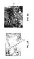
- FIGS. 2 a and 2 c are two histological cross-sectional pictures showing collagen structures in skin.
- FIG. 2 b is an illustration of Langer's cleavage lines.
- FIG. 3 is a cross sectional view of a concept for a tissue imaging system from the cross-referenced copending U.S. patent application Ser. No. 11/087,183.
- FIG. 4 a is a view of the first embodiment for a programmable confocal tissue imaging system of the present invention.
- FIG. 4 b is a cross-sectional view of a representative design for an objective lens for a tissue imaging system of the present invention.
- FIG. 4 c is a view of an alternate embodiment of an imaging sub-system for a tissue imaging system of the present invention.
- FIG. 4 d is a cross sectional view of an alternate embodiment of an imaging sub-system within a tissue imaging system of the present invention.
- FIG. 4 e is a view of an alternate embodiment for a tissue imaging system of the present invention to have a controlled interaction with the tissue being examined.
- FIG. 5 is a cross sectional view of an alternate embodiment for a tissue imaging system of the present invention.
- FIG. 6 is a cross sectional view of an alternate embodiment for a tissue imaging system of the present invention.
- FIG. 7 is a cross sectional view of an alternate embodiment for a tissue imaging system of the present invention.
- FIG. 8 is a view of an alternate application for a tissue imaging system of the present invention that provides diffuse optical tomography operation.
- FIG. 9 is a view of alternate embodiments of a tissue imaging system of the present invention that are provided with optical coherence tomography capabilities.
- FIG. 10 is a view of an alternate embodiment of a tissue imaging system of the present invention that employs a digital mirror device (DMD) modulator.
- DMD digital mirror device
- FIG. 11 is a schematic view of yet another embodiment of a tissue imaging system according to the present invention.
- the present invention is generally directed at providing an optical device appropriate for imaging deep tissue injuries, and in particular, for examining wounds and the surrounding tissues.
- the device is intended to image a significant diagnostic area (for example ⁇ 1 cm 2 ) with a modest resolution ( ⁇ 4 ⁇ m) appropriate foe examining cellular morphology and extra-cellular structures.
- the device of the present invention also preferably enables multi-modal imaging in one device, as an approach to maximizing its diagnostic utility.
- FIG. 1 depicts the cross-sectional composition of skin.
- Skin 100 (or the integument) covers the entire external surface of the human body and consists of two mutually dependent layers, the epidermis 105 and the dermis, which rest on a fatty subcutaneous layer, the panniculus adiposus (not shown).
- the epidermis 105 which is the outer layer of skin, is made up of epithelial cells (also known as squamous cells or keratinocytes), basal cells, and melanocytes.
- the outermost layer of the epidermis 105 comprises layers of dead epithelial cells 110 .
- the basal cells are responsible for producing the epithelial cells, while the melanocytes produce pigments (melanin) that give skin its color.
- Below the epidermis 105 is the basement membrane 115 (also known as the basal lamina), which helps attach the epidermis 105 to the reticular dermis 120 .
- the basal lamina 115 actually comprises several layers, and includes proteoglycans and glycoproteins as well as Type IV collagen.
- the innermost layer of the basal lamina 115 includes several types of fibrils, including collagen Type III and Type VII fibrils, which help anchor to the dermis.
- the dermis comprises several layers, including the papillary dermis (not shown) and the reticular dermis 120 , which is the primary dermal layer.
- the papillary dermis is composed of fine networks of Types I and III collagen, elastic fibers, capillaries and fibroblasts.
- the reticular dermis 120 contains thick collagen bundles (thicker than the papillary dermis), which are generally arranged in layers parallel to the surface of the skin. In FIG. 1 , the reticular dermis 120 is shown, with constituent blood capillaries 125 with transiting red blood cells 127 , fibroblasts 140 , collagen fiber bundles 145 , and proteoglycans 130 .
- Proteoglycans 130 are large molecules that attract and hold water, thereby providing cushioning and support.
- the reticular dermis 120 also contains other structures (not shown), such as elastin, sebaceous glands, sweat glands, hair follicles, and a small number of nerve and muscle cells.
- the dermal skin layers vary with body location. For example, skin is quite thin on the eyelids, but is much thicker on the back and the soles of the feet.
- the epidermis ranges in thickness from ⁇ 30 microns to ⁇ 1 mm, while the dermis (papillary and reticular) ranges between ⁇ 300 microns and ⁇ 3 mm in thickness.
- the collagen structure in skin also varies with location, as will be discussed subsequently.
- Fibroblasts create many of the components of the connective tissue in the reticular dermis, including the elastin, fibronectin, and collagen, which are all complex fibrous proteins.
- Collagen actually comprises long bundles or strands, composed of innumerable individual collagen fibrils.
- Fibroblasts synthesize collagen (both Type I and Type III), in a process beginning with procollagen, which is polymerized outside the fibroblasts to form tropocollagen, which in turn is formed into collagen fibrils and collagen bundles.
- the collagen fibril segments are ⁇ 25-50 microns in length and ⁇ 10-200 nm in diameter (depending on type).
- Type III collagen fibers are generally thinner than the Type I fibers.
- the most structured collagen formations are found in bones and tendons.
- the collagen structures in tendons, ligaments, and vocal cords which are termed “dense regular” and have collagen fibers in parallel alignment, are structured to handle stresses and transmit forces along their length.
- the collagen structures in skin in which the collagen fibrils and bundles are less organized and somewhat wavy or convoluted, are termed “dense irregular.”
- the collagen network which is multi-directional and multi-layered, is an interwoven mesh generally parallel to the surface of the skin, which gives skin its toughness and adaptability. However, there is a pre-dominant direction to the orientation of the fiber bundles in a given location.
- Langer's cleavage lines 165 are generally associated with the alignment of collagen bundles deep in the reticular dermis. These lines portray the directional effects of skin across the human body 160 , wherein the stress-strain relationships in uniaxial tension show skin to be stiffer along Langer's lines than across the lines. Langer's lines 165 are used as guides in surgery, with incisions preferentially running along the lines rather than cutting obliquely through them.
- Collagen bundles that follow Langer's lines may interconnect over several millimeters, or even centimeters or more in extent. Some common directionality, at least on a local scale of a few hundred microns, is evident in the collagen structures in the skin of FIG. 2 a . Collagen fibers generally do not often branch and, when branches are found, they usually diverge at an acute angle (see FIG. 1 ).
- the natural mesh-like arrangement of collagen fibers in skin allows continual rearrangement of individual fibers to resist severe stretching under the minimal stresses associated with normal activity. At rest, the collagen fibers are irregularly organized, but when an increasing load is applied, the fibers change geometrical configuration and become parallel.
- the interconnected elastin fibers are able to stretch much more than the collagen fibers, and likely assist the collagen fibers to return to their original alignment after the forces have been removed.
- the water, proteins, and macromolecules (proteoglycans) function as lubricants during deformation.
- Wounds are characterized in several ways; acute wounds are those that heal normally within a few weeks, while chronic wounds are those that linger for months or even years.
- Wounds that heal by primary union are wounds that involve a clean incision with no loss of substance. The line of closure fills with clotted blood, and the wound heals within a few weeks.
- Wounds that heal by secondary union involve large tissue defects, with more inflammation and granulation. Granulation tissue is needed to close the defect, and is gradually transformed into stable scar tissue.
- Such wounds are large open wounds as can occur from trauma, burns, and pressure ulcers. While such a wound may require a prolonged healing time, it is not necessarily chronic.
- a chronic wound is a wound in which normal healing in not occurring, with progress stalled in one or more of the phases of healing.
- Typical chronic wounds are pressure, friction ulcers, and venous stasis ulcers.
- Chronic wounds often include necrotic tissue, which can comprise a mix of marginal cells, dead cells, and deteriorated extracellular structures.
- marginal cells which have impaired function, may also have cell morpohologies (shape and size) that are different from those of normal cells.
- excess levels of MMPs matrix metallo-proteinases
- gelatinase and collagenase can cause extra-cellular supportive structures, such as collagen, to break down.
- Wound healing also progresses through a series of overlapping phases, starting with coagulation (haemostasis), inflammation, proliferation (which includes collagen synthesis, angiogenesis, epithelialization, granulation, and contraction), and remodeling.
- Haemostasis, or coagulation is the process by which blood flow is stopped after the initial wounding, and results in a clot, comprising fibrin, fibronectin, and other components, which then act as a provisional matrix for the cellular migration involved in the later healing phases.
- Many of the processes of proliferation such as epithelialization and angiogenesis (creation of new blood vessels) require the presence of the extracellular matrix (ECM) in order to be successful.
- ECM extracellular matrix
- Fibroblasts appear in the wound during that late inflammatory phase ( ⁇ 3 days post injury), when macrophages release cytokines and growth factors that recruit fibroblasts, keratinocytes and endothelial cells to repair the damaged tissues. The fibroblasts then begin to replace the provisional fibrin/fibronectin matrix with the new ECM.
- the ECM is largely constructed during the proliferative phase ( ⁇ day 3 to ⁇ 2 weeks post injury) by the fibroblasts, which are cells that synthesize fibronectin and collagen.
- other cell types such as epithelial cells, mast cells, endothelial cells (involved in capillaries) migrate into the ECM as part of the healing process.
- Fibroblasts initial role in wound healing is to provide fibronectin, which is a glycoprotein that promotes cellular adhesion and migration. Fibronectin weaves itself into thread-like fibrils, with “sticky” attachment sites for cell surfaces, to help connect the cells to one another. There is some directionality to the deposition of fibronectin, which in turn impacts the deposition of the other ECM proteins. Fibroblasts synthesize collagen (both Type I and Type III), beginning with procollagen, which is three polypeptide chains (each chain is over 1400 amino acids long) wound together in a tight triple helix. Procollagen is then extruded from the fibroblasts out into the extracellular space.
- procollagen is three polypeptide chains (each chain is over 1400 amino acids long) wound together in a tight triple helix. Procollagen is then extruded from the fibroblasts out into the extracellular space.
- the triple-helical molecule undergoes cleavage at specific terminal sites.
- the helix is now called a tropocollagen molecule, and tropocollagens spontaneously associate in an overlapping array.
- the amassing continues as tropocollagen convolves with other tropocollagen molecules to form a collagen fibrin.
- Wound durability, or tensile strength is dependent on the microscopic welding (cross-linking) that must occur within each filament and from one filament to another.
- the collagen fibril segments are ⁇ 25-50 microns in length and ⁇ 10-200 nm in diameter (depending on type).
- the fibril segments fuse linearly and laterally (crosslink) to form longer, thicker, biomechanically competent collagen fibrils within collagen bundles 145 .
- Collagen deposition will align itself to the fibronectin pattern, which in turn mirrors the axis of the fibroblasts.
- the initial collagen deposition may appear somewhat haphazard, the individual collagen fibrils are subsequently reorganized, by cross-linking, into more regularly aligned bundles oriented along the lines of stress in the healing wound, and eventually, at least partially, to the stress lines associated with the surrounding tissue.
- Type III collagen is the type that appears in the wound initially, starting at about 4 days after injury. Collagen becomes the foundation of the wound ECM, and if collagen formation does not occur, the wound will not heal.
- Myofibroblasts which are a specialized fibroblast, appear late during the proliferative phase (at ⁇ 5 days), to help contract the wound so that there will be less scarring. Wound contraction helps to further organize the early collagen structures. A ring of these contractile fibroblasts convene near the wound perimeter, forming a “picture frame” that will move inward, decreasing the size of the wound. Linear wounds contract rapidly, square or rectangular wounds contract at a moderate pace, and circular wounds contract more slowly.
- fibroblasts continue to work to build more robust tissue structures.
- Matrix synthesis and the remodeling phase are initiated concurrently with the development of granulation tissue and continue over prolonged periods of time ( ⁇ 30-300 days, depending on the injury).
- fibronectin and hyaluronan a component of the proteoglycans
- Type III collagen is fairly quickly replaced by Type I collagen, which constitutes 90% of the total collagen in the body, and forms the major collagen type found in the reticular dermis.
- the collagen structure is altered on an ongoing basis, by a process of lysis and synthesis.
- Collagen degradation is achieved by specific MMPs (matrix metalloproteinases) that are produced by many cells at the wound site, including fibroblasts, granulocytes and macrophages.
- MMPs matrix metalloproteinases
- the Type I collagen bundles are deposited with increasing organization, orientation, and size (including diameter), to better align to the surrounding tissues and increase wound tensile strength.
- Stage 3 and Stage 4 pressure ulcers are open wounds that can occur whenever prolonged pressure is applied to thin skin and tissue layers covering bony prominences, such as at the hips and sacrum. For example, patients who are bedridden are at risk of developing pressure ulcers. Stage 4 pressure ulcers can form in 8 hours or less, but take months or years to heal.
- Pressure ulcers are complicated wounds, which can be large (many square inches in area) include infection, slough (dead loose yellow tissue), black eschar (dead blackened tissue with a hard crust), hyperkeratosis (a region of hard grayish tissue surrounding the wound), and undermining or tunneling (an area of tissue destruction extending under intact skin). Pressure ulcers may have closed wound edges (epibole), which impedes healing. In such circumstances, the top layers of the epidermis have rolled down to cover lower edge of epidermis, including the basement membrane, so that epithelial cells cannot migrate from wound edges.
- FIG. 2 b shows a scar-like mass of dense collagen fiber bundles from tissues near the boundary of a pressure ulcer.
- the resolution at the tissue need not be sub-cellular, and could be in the ⁇ 2-7 ⁇ m range.
- NA numerical aperture
- the numerical aperture (NA) of the objective lens is reduced, for example to ⁇ 0.2-0.3 from the ⁇ 0.7-1.4 values typical of OCT and confocal systems, thus simplifying the objective lens design (for example, thus obviating the need for immersion objectives).
- NA numerical aperture
- optical diagnostic device which is designed and used with recognition of these properties, is likely to provide more clinically useful data than an off the shelf system.
- Most optical tissue imaging systems are designed to operate within the spectral range of 600-1200 nm, where light attains its deepest penetration, because the light absorption coefficient ( ⁇ a ) is relatively small (0.01-1 mm ⁇ 1 ). In this spectral regime, the interaction of light with tissue is dominated by scattering (the scattering coefficient ⁇ s is ⁇ 100 ⁇ greater than the absorption coefficient ⁇ a ) where the total attenuation coefficient ⁇ T is given by equation (1).
- a polarization sensitive imaging system could, under the proper circumstances, probe more deeply than a polarization insensitive system. Further then, a polarization sensitive imaging system could then be used to look at collagen, and other optically birefringent structures, in skin. It is likely that part of the reason granulation tissue has higher optical transmission, is that the collagen network is less fully formed.
- a polarization sensitive imaging system could be used to look at collagen structures, or the lack thereof, in tissues, so as to determine the extent of damage.
- a device could be used to examine necrotic or semi-necrotic tissues, to help determine why the tissue is damaged, or where the tissue boundaries are.
- this device could be used to examine the condition of the rebuilding collagen in granulation tissues. More generally, it is recognized that successful collagen formation and remodeling is very important in wound healing, whether the wounds are acute (primary or secondary) or chronic, and whether the wounds are in the inflammatory phase, the proliferative phase, or the remodeling phase, or a combination thereof.
- the diagnostic device of the present invention does not need to be limited to examining the collagen network, as a means for determining tissues status.
- Both elastin and fibronectin which are elongated thread like proteins, are likely optically birefringent and could potentially be detected.
- fibronectin is deposited prior to collagen Type I, detection of fibronectin could enable examination at an earlier point in the healing process.
- capillaries which are tubules that are constructed in part with Type IV collagen, are known to be optically birefringent. Detection and tracking of capillary formation (angiogenesis) with the device of the present invention in tissue undergoing granulation and remodeling could also be useful in understanding tissue status. Additionally, muscles (which comprise a birefringent filamentous protein f-actin), nerves (which includes sheaths of birefringent myelin covering the axons), and amyloids (starch like birefringent proteins that aggregate and impair function, for example in Alzheimer's disease) might all be examined using the device of the present invention.
- f-actin a birefringent filamentous protein f-actin
- nerves which includes sheaths of birefringent myelin covering the axons
- amyloids starch like birefringent proteins that aggregate and impair function, for example in Alzheimer's disease
- Isotropic (homogeneous) media such as glass
- Anisotropic media may have either two or three indices of refraction.
- Uniaxial media such as liquid crystals
- n o the ordinary index
- n e the extraordinary index
- the axis of n e is also referred to as an optical axis.
- Uniaxial materials are uniquely characterized by n e , n o , and two angles describing the orientation of its optical axis.
- Retardance is the phase change ⁇ expressed as distance; for example a ⁇ /2 phase change ⁇ corresponds to a quarter wave ⁇ /4 retardance, which at 550 nm equals ⁇ 138 nm retardance.
- birefringent When viewed under polarized light, however, anisotropic materials will be brightly visible in one plane (“birefringent”), but will be dark in a plane turned 90 degrees.
- the refractive index of human tissue is n ⁇ 1.4-1.5, depending on the tissue and the wavelength.
- Both Type I and Type III collagens are birefringent, with nominal optical birefringence values of ⁇ n ⁇ 3 ⁇ 10 ⁇ 3 .
- a tissue imaging system 200 comprises an illumination system 205 and a detection system 210 (linked by a controller (not shown) and a beamsplitter 260 ), which are both directed at the same nominal portion of tissue 290 .
- FIG. 3 is not to scale; the optical systems likely measure several inches end to end, but the depth of the tissue examined is only ⁇ 2-4 mm.
- the illumination system 205 nominally comprises a light source and illumination beam shaping optics.
- Light source can be a lamp (such as tungsten halogen, metal halide, or UHP), an LED (light emitting diode), a SLD (super-luminescent diode), a laser diode, a solid state laser, or other light source, such as an array with multiple light emitters 225 .
- the beam-shaping optics can comprise a condenser lens 230 , a pre-polarizer 250 , spectral filters (not shown), light uniformization optics, and field lenses (such as field lens 240 ), as well as other components.
- Optical detection system 210 nominally comprises an objective lens 270 that provides an image of the tissue 290 on detector 280 .
- Detector 280 is nominally a detector array, such as a charge coupled device (CCD) or a complementary metal oxide semiconductor (CMOS) device.
- Detector 280 is nominally an area sensor device with a row and column structure.
- An exemplary device could be the Kodak KAF-6303, which comprises an array of 3072 ⁇ 2048 pixels, with a nominal 9 micron pixel pitch. Incident light provided by the illumination system 205 will penetrate the tissue 290 .
- Tissue imaging system 200 is nominally equipped with at least two linear optical polarizers, pre-polarizer 250 and polarization analyzer 255 that are provided to enable detection of the birefringent tissue structures.
- pre-polarizer 250 or a waveplate 252 rotates around the illumination optical axis 247
- polarization analyzer 255 rotates about the imaging optical axis 277 .
- polarizers are nominally orthogonal to their respective axes, although they may be tilted (likely by a few degrees) away from orthogonality, to control the direction of any ghost reflections, to thereby improve image contrast.
- pre-polarizer 250 and polarization analyzer 255 are nominally crossed (90 degrees rotationally apart) to define extinction axes.
- Light from the illumination system 205 is then incident on the tissue 290 with an initial linear polarization alignment. Some of this light will penetrate the tissue 290 , and another portion will be specularly reflected from the first surfaces (the superficial layers: the epidermis 105 and papillary dermis) of the tissue. This specularly reflected light tends to retain the polarization state of the illumination light.
- the polarization sensitive optics enable the imaging of the birefringent tissue structures by enabling detection of changes in the polarization state of the low level diffused light re-emerging from the tissue, while eliminating the strong initial back reflection off of the front surface, which could otherwise provide a dominant return signal and reduce the contrast of the images of the birefringent tissue structures.
- the image quality of the collagen network depends on the relative alignment of the crossed polarizers ( 250 and 255 ) to any given portion of the network.
- the concept of the FIG. 3 system anticipates that the crossed polarizers should be rotated in unison so that the extinction axes rotate into various positions relative to the tissue 290 . This is facilitated by controller, which sends drive signals to mechanisms (not shown), such as stepper motors, which separately drive pre-polarizer 250 and polarization analyzer 255 to rotate about their respective optical axes.
- Nominally crossed polarizers 250 and 255 each rotate by the same angular amount ⁇ , so that they remain crossed.
- Crossed polarizers 250 and 255 nominally are rotated in a stepwise fashion through N steps, of some set amount ⁇ , until the crossed polarizers have both swept through at least 90 degrees.
- the controller would drive the light source to provide illumination light and detector 280 to capture a digital image.
- the controller could employ image-processing algorithms to build one or more composite high contrast images. These image-processing algorithms could perform various functions (sharpening, contrast changes, false color, etc.) to enhance image quality/wound visualization. It was further proposed that this device could be used in a therapeutic mode, using illumination system 205 , to provide light for light therapy.
- the light source (using spectral filters or different sources) could sequentially provide illumination light with an increasing nominal wavelength, starting at ⁇ 530 nm (to image structures within the first ⁇ 0.5 mm tissue depth), then ⁇ 600 nm (to image structures within the first ⁇ 1 mm tissue depth), then ⁇ 630 nm (to image within the first ⁇ 2 mm tissue depth), and ⁇ 830 nm light (to image within the first ⁇ 3.5 mm tissue depth). Then for each rotational position of the crossed polarizers 250 and 255 , the controller could capture digital images for each tissue depth.
- the controller could apply a form of spectral polarization difference imaging, such that data for shallower images was subtracted from the original data for deeper images, to remove scatter and birefringence effects caused by the shallower images. While this approach may work for some tissue types, perhaps including granulation tissues, for tissues such as skin (particularly the dermis 120 ), which are affected by strong optical scattering, the effectiveness may be limited when attempting to image deeper and deeper into the tissues.
- FIG. 4 a depicts a system that includes a spatial light modulator array 300 , which is nominally image conjugate to both the tissue 290 and the detector 280 .
- FIG. 4 a is a conceptual illustration, with most components shown in cross-section, except for spatial light modulator array 300 , which is shown in perspective. The components of the system of FIG. 4 a are not shown to scale.
- a light source 220 is used to illuminate the spatial light modulator array 300 , via exemplary illumination optics which comprise a diffuser 222 , an integrating bar 235 , a condenser lens 230 , fold mirror 232 , and beamsplitter 260 .
- This illumination system which is intended to flood illuminate the entire top surface of spatial light modulator array 300 , should provide improved illumination uniformity as compared to other classical approaches (such as Kohler and Abbe illumination).
- light from light source 220 may be directed to (optional) diffuser 222 , which diffuses the light into integrating bar 235 .
- the output face of integrating bar 235 is then imaged to the modulator array 235 , to flood the surface with uniform (nominally within a few %) light.
- an illumination system with a Fly's Eye optical integrator can also be used to provide enhanced illumination uniformity.
- Modulator field lens 305 can be used to modify the incident illumination light to be telecentric to the spatial light modulator array 300 .
- Objective lens 325 then images the modulator array 300 into the tissue 290 , and then collects return light from the tissue 290 , which it images back to the spatial light modulator array 300 .
- Modulator 300 , objective lens 325 , and focus mechanism 335 can also be defined as the scan arm of tissue imaging system 200 .
- Imaging lens 340 in cooperation with modulator field lens 305 , then images modulator array 300 to the detector array 280 .
- the system can also be equipped with a pre-polarizer 250 and a polarization analyzer 255 . As compared to the prior system of FIG. 3 , this system is enhanced primarily by the use of spatial light modulator array 300 , and the change of the objective lens to a doubly-telecentric (nominally telecentric in both object and image spaces) design.
- the tissue imaging system of FIG. 4 a is primarily intended to operate as a flexible confocal imaging system, with the confocal imaging modality enabled by modulator array 300 , which functions as a programmable pinhole.
- modulator array 300 is depicted with 4 addressed modulator pixels 310 “shaded,” to indicate that they are simultaneously “open” to allow light down to the tissue and back.
- spatial light modulator array 300 is preferably a transmissive device, because the overall size of the tissue imaging system 200 is likely then reduced.
- One exemplary device is the “flixel” from Flixel Ltd.
- Another exemplary device which is also a micro-electromechanical (MEMS) device, is the coiled or rolled shutter modulator, which is described in U.S. Pat. No. 5,784,189 (Bozler et al.). Both of these devices function by moving a micro-mechanical shutter, which blocks the light when closed, but which is moved out-of-the-way, to provide open state transmission.
- MEMS micro-electromechanical
- these devices are advantaged in that the phase structure of the passing light beams is less likely to be altered in transit, and therefore, the effective resolution of the light imaged to the detector 280 may be better.
- Another candidate modulator technology is the polymer dispersed type liquid crystal display (LCD). It modulates light by causing the transiting light to scatter within an off-state pixel, while having high transmission and low scatter for an on-state (field applied) pixel.
- LCD liquid crystal display
- Such a device could impart residual phase distortions to the transiting image light or require a Schlieren type stop, located for example at aperture stop 330 , to filter out the off-state light from the on-state light.
- a modulator pixel 310 when a modulator pixel 310 is open (or on-state), illumination light would travel through objective lens 325 and illuminate small portions of a sample or specimen, such as tissue 290 . Return light from tissue 290 would be spatially filtered by the same pixel at modulator array 300 . This light would then deflect off beamsplitter 260 and be imaged by imaging lens 340 to detector 280 , which may be a CCD device, a CMOS, or other type of detector array. A given modulator pixel 310 would then provide the functionality of a pinhole in a confocal microscope. After given pinhole image captures, controller 360 would then provide signals to modulator array 300 to change the combination of open pinholes to a new configuration.
- a series of pinhole image captures would be completed such that a complete confocal image could be completed at a given plane within tissue 290 .
- the focal position within the tissue could be changed, for example, through the use of focus mechanism 335 (shown as a wedge prism pair, which are adjusted laterally relative to one another, to alter the optical path length) under the control of controller 360 .
- a complete confocal image could then be captured at the new plane within the tissue.
- a complete 3D image could be obtained, spanning a given tissue area and depth.
- a doubly-telecentric objective lens 325 be used, so that the illumination light and the return light travel through the same modulator pixel (pinhole).
- the light returning to the modulator site is likewise exiting non-normally to the target (tissue).
- the angles of incidence and collection will vary over the target plane. As area images are re-assembled at different depths, this could cause parallax and distortion image errors.
- the system could benefit from less aberration (field curvature) and higher light collection efficiency and uniformity from the tissue.
- the refocusing of a double telecentric imaging lens 325 to alternate conjugate image planes is different than occurs with a normal imaging lens, as the chief ray heights are fixed. Such refocusing can then cause both a magnification change and vignetting at the aperture stop.
- the system of FIG. 4 a is depicted with a wedge plate focus mechanism 335 being used on the tissue (short conjugate) side of the lens.
- the effective glass thickness is changed, and thus the optical path length and focal position within the tissue is changed, and yet the magnification is held constant and vignetting is avoided.
- the target focus plane within tissue 290 can then be adjusted to different axial locations within the tissue.
- tissue imaging system 200 could utilize a modulator array 300 comprising pixels 310 that are 17 microns square. If the objective lens 325 images to the tissue with 4.25:1 de-magnification and a short conjugate NA of ⁇ 0.25, then the geometrical size of the imaged “pinhole” in the tissue is d g ⁇ 4.0 microns.
- An exemplary objective lens 325 as shown in FIG. 4 b , does not require exotic glasses or unusually difficult lens elements.
- a reflective design could also be used, but should not be necessary, given the limited source bandwidth and small target NA at the tissue. This exemplary lens is designed to image with a ⁇ 1 inch working distance between the last element and the target plane.
- An exemplary modulator array 300 with a ⁇ 1.95 inch diagonal and ⁇ 4 Mpixels is then imaged to the tissue to address an area of ⁇ 0.7 cm ⁇ 2, which should be large enough for useful diagnostic application.
- a confocal term, the virtual pinhole diameter Vp at the target plane, which can be estimated by equation (3), is a metric that can be used to anticipate the confocal optical imaging depth and confocal resolution in the tissue.
- the imaging depth (D Z ) is scalable with the mean free path, which is the inverse of the total attenuation coefficient ⁇ T , with the scaling factor (A) depending on the value of the virtual pinhole diameter Vp.
- the confocal lateral resolution dr which is different than the geometrical size of the imaged pinhole, is scalable to the minimum confocal resolution r conf by a factor (B), which is determined by the value of Vp.
- V p ⁇ *d g *NA/ ⁇ (3)
- Vp virtual pinhole diameter
- lateral and axial resolution, imaging depth, and signal to noise ratio are all maximized, but at the cost of decreased optical signal strength.
- a virtual pinhole diameter Vp ⁇ 3.9 is estimated for a wavelength of 810 nm.
- the imaging depth D Z for this system can be estimated by the equation (4) as 0.2-0.35 mm.
- the imaging depth in granulation tissue can be expected to improve accordingly.
- an estimated granulation tissue scattering coefficient ⁇ s ⁇ 1.8 mm ⁇ 1 an estimated confocal imaging depth D Z ⁇ 1.7-2.6 mm is obtained.
- a confocal imaging system could potentially image a few mm into granulation tissues, and perhaps other wound tissues such as necrotic and semi-necrotic tissues.
- the estimated lateral resolution, dr ⁇ 4 microns, should be sufficiently small to image both extra-cellular tissue structures and the morphology of many cell types to be useful in examining wound tissues.
- FIG. 4 a embodiment of the present invention can have other attributes and features that enhance its utility.
- the system of FIG. 4 a may also have dual diagnostic and therapeutic use. Most simply, if all the modulator pixels 310 are controlled to an open state, then the tissue 290 could be flood illuminated with light for therapeutic purposes. Likewise, if all the modulator pixels 310 were at an open-state, and the detector array 280 was operated for image capture, then system 200 could operate as a digital camera or microscope and capture photographic images of the tissue 290 .
- the tissue imaging system 200 can have other attributes and functions beyond operation as a camera or light therapy device. As one possibility, consider that as a wound heals and granulation tissue becomes more like normal skin tissue or scar tissue, the scattering would likely increase and the imaging depth would then be diminished. On the other hand, as reported in the previously cited paper by Nickell et al., skin has a polarization anisotropy based on collagen orientation, such that light polarized parallel to the collagen orientation experiences a reduced scattering coefficient ⁇ 2 ⁇ smaller than normal. This suggests that a polarization sensitive confocal-type imaging system could collect this parallel-polarized light, and thus enable deeper imaging within some tissues. As an example, then applying an estimated collagen parallel scattering coefficient ⁇ s ⁇ 4.9 mm ⁇ 1 , a confocal imaging depth of D Z ⁇ 0.7-1.0 mm is predicted.
- the tissue imaging system 200 of FIG. 4 a can be equipped with optical polarizers, such as pre-polarizer 250 and polarization analyzer 255 .
- optical polarizers such as pre-polarizer 250 and polarization analyzer 255 .
- polarization analyzer 255 is stepwise rotated by controller 360 through various angular positions from 0-90°, so that the light parallel polarized to the collagen at a given tissue depth, but at various combinations of location and orientation within the field of view, can then be imaged.
- polarization analyzer 255 can be held in a position which is nominally orthogonal or crossed with respect to polarization analyzer 255 , and then be stepwise rotated in synchronization with polarization analyzer 255 . In this way, specular surface reflections from the first surface of the tissue can be minimized.
- the polarization analyzer 255 can be driven to both parallel and orthogonal positions, with image captures then occurring.
- a polarization difference image, with the polarization parallel image subtracted from the polarization perpendicular image (and normalized by the sum of the two) could then be compiled, so as to emphasize the deeply penetrating light.
- a strong “first” surface polarized reflection may be absent.
- the pre-polarizer 250 and polarization analyzer 255 could be aligned parallel (rather than crossed, and then rotated in tandem by controller 360 .
- a linear pre-polarizer 250 could be followed by a waveplate to produce circularly polarized illumination light.
- the return light would tend to be circularly polarized, and polarization analyzer 255 could be rotated to various positions to detect the aligned image information. Alternately, pre-polarizer 250 may be removed altogether, but that could result in an increase in the noise level from stray light reaching the detector 280 .
- polarization optics used in the polarization diagnostic device of the present invention can be important.
- Many prior art optical systems have been described which use MacNeille type thin film prisms (U.S. Pat. No. 2,403,731), pulled polymer sheet polarizers (“Polaroid” polarizers), or bulk birefringent crystalline prisms (such as calcite).
- Polymer sheet polarizers pulled polymer sheet polarizers (“Polaroid” polarizers”
- bulk birefringent crystalline prisms such as calcite.
- visible wavelength wire grid polarizers have been developed. These polarizers, which are available from Moxtek (Orem, Utah), and which are described in U.S. Pat. No. 6,122,103 (Perkins et al.) and U.S. Pat. No.
- both pre-polarizer 250 and polarization analyzer 255 are preferentially wire grid polarizers.
- polarization analyzer 255 might actually be two consecutive wire grid polarizers, with the second one provided to remove residual leakage light from the first, and thus enhance the contrast.
- both polarizers would rotate together as a pair, although the two polarizers might be tilted relative (by a few degrees, or near parallel) to each other to control ghost reflections.
- a polarization analysis subsystem could be utilized, with a waveplate 265 , a polarization analyzer 255 (preferably a wire grid polarizer) and a wire grid polarization beamsplitter 257 (the latter is a wire grid polarizer nominally tilted at 45 degrees relative to the optical axis of detection system 210 , and performance optimized for the tilt).
- a polarization analyzer 255 preferably a wire grid polarizer
- a wire grid polarization beamsplitter 257 the latter is a wire grid polarizer nominally tilted at 45 degrees relative to the optical axis of detection system 210 , and performance optimized for the tilt.
- the incoming image light returning from the tissue would be transmitted through the waveplate 265 , the polarization analyzer 255 and the wire grid polarization beamsplitter 257 , before reaching detector 280 .
- waveplate 265 could also be an electro-optical device, such as liquid crystal device, which would provide an amount or polarization rotation in response to a commanded signal. In this way, the use of rotating mechanical part could be avoided and the capture time is reduced.
- the polarization contrast of this system could further enhanced with the use of a polarization compensator (not shown), for example, located prior to wire grid polarization beamsplitter 257 .
- This compensator could correct for angular response variations of the beamsplitter 257 .
- the polarization design of the illumination system 205 is also worth further consideration.
- light source 220 emits polarized light (for example if it comprises one or more laser diodes, then pre-polarizer 250 could be replaced with a waveplate (nominally ⁇ /4) which would rotate the polarization state of the incident light relative to tissue 290 .
- the light source 220 emits unpolarized light, it could be disadvantageous to build the illumination system 205 with a pre-polarizer without first (or instead) providing a polarization conversion device, as otherwise as much as 50% of the available light will be lost right up front. While there are many polarization conversion designs known in the art, one particularly advantageous design and compact is described in U.S. Pat. No.
- pre-polarizer 250 could comprise a rotating polarization converter, or a fixed polarization converter and a rotating waveplate.
- polarizer technologies with high contrast and transmittance, as well as a large angular acceptance, could be used in place of wire grid polarizers.
- photonic crystal polarizer which theoretically has an excellent field-of-view and wavelength acceptance.
- photonic crystal polarizers are presently fabricated using expensive lithographic processes.
- the potential utility of the tissue imaging system 200 can also be enhanced or expanded relative to the light source 220 .
- light source 220 is illuminating with a spectra residing within a spectral window from ⁇ 500 nm to ⁇ 1200 nm.
- the illuminating spectra may be broad ( 40 nm or greater) or quite narrow (1-4 nm). Multiple light sources with different emission spectra may also be used.
- the illumination light can then scatter off of tissue structures in the target plane, with some portion thereof imaged back to the modulator array 300 and onto the detector 280 .
- the illumination light could excite fluorescent emissions within the tissue, and fluorescent light could be imaged.
- collagen when collagen is illuminated with ⁇ 400 nm light, it produces a strong fluorescence at ⁇ 480 nm.
- the detection of the fluorescent light could be enhanced by providing one or more filters in the detection system 210 , which could be either fixed spectral filters or tunable spectral filters (such as a liquid crystal tunable filter).
- collagen fluorescence is reduced as a byproduct of the action of MMPs (such as collagenase) to degrade collagen, as can happen in wounds, then imaging collagen fluorescent light could be useful in wound assessment to look at tissue deterioration.
- MMPs such as collagenase
- collagen fluorescence from the longer illumination wavelengths (>600 nm) necessary for deep tissue penetration is much reduced.
- other fluorescence techniques such as second harmonic generation and multi-photon excitation could be used, but as the requisite light sources are typically expensive high power femto-second pulsed lasers, use thereof in tissue imaging system 200 would likely cause the system to exceed the size and cost targets desired for this application.
- beamsplitter 260 can be designed using any one of several technologies. Generally speaking, either the detection channel light (as in FIG. 3 ) or the illumination light (as in FIG. 4 a ) can be transmitted through the beamsplitter (relative to the tissues 290 ). Beamsplitter 260 , for example, can most simply be an intensity splitter (prism/cube or plate), that for example, transmits 60% of incident light and reflects 40% of incident light. Alternately, beamsplitter 260 can be an angle sensitive TIR prism, much as depicted in FIG.
- TIR total internal reflection
- beamsplitter 260 could be a dichroic, which would selectively reflect and transmit light on the basis of wavelength (excitation or emission). If there were multiple fluorescent emission wavelengths that needed to be distinguished, a Color Select filter or a Color Switch filter from ColorLink of Boulder, Colo., could be used in the detection channel, to selectively rotate the polarization states of one wavelength and not another. A polarizer could then follow, which would attenuate one wavelength and allow the other through to the detector 280 .
- the configuration could be similar to that of FIG. 4 c , where waveplate 265 could be a wavelength selective polarization switch.
- beamsplitter 260 could be a polarization beamsplitter (such as a wire grid PBS or a MacNeille type PBS) that transmits one polarization state, while reflecting the other.
- polarization beamsplitter such as a wire grid PBS or a MacNeille type PBS
- this could mean that the entire tissue imaging system 200 would then have to be rotated relative to tissue 290 .
- FIG. 4 c also shows that the tissue imaging system could be equipped with a pupil filter 332 , nominally located in the aperture stop plane 330 of objective lens 325 .
- a pupil filter 332 could be used to help control or define the axial resolution of the system.
- Pupil filter 332 could have an annular design or a central obscuration, providing a zonal pattern that modifies the intensity (apodizing) and/or phase of the transiting light.
- the use of a pupil filter 332 may also improve the signal to noise ratio of the imaging light.
- a Fourier plane filter (not shown) could also be used at the aperture stop of the imaging lens 340 , for various purposes, including to filter out the periodic structure signatures of the spatial light modulator array 300 .
- spatial light modulator array 300 was a device with 4 Mpixels, or ⁇ 4 million addressed “pinholes.”
- the detector array 280 In collecting the tissue images, for improved spatial resolution, it may be desirable the detector array 280 to be provided with more detection pixels than there are modulator pixels. For example, with a ratio of 4 ⁇ , detector array 280 would then have 16 Mpixels. While image sensors are available today with 14 Mpixels or more, data handling, data storage, image processing, and signal to noise ratios may all be affected by increasing the pixel count of the detector array 280 .
- FIG. 4 d depicts an approach for optically multiplexing the detector pixels.
- imaging lens 340 would project or create an intermediate real image, which is image conjugate to spatial light modulator array 300 . That image would then be optically sub-sampled by an optical system comprising first lenslet array 345 , second lenslet array 350 , and field lenslet array 355 . Second lenslet array 350 and field lenslet array 355 would work together to project a magnified image to detector array 280 . First and second lenslet arrays 345 and 350 would be paired, so that first lenslet array 345 would act as a field lens relative to the input image plane, and nominally focus light into the aperture stop of the corresponding lenslet of second lenslet array 350 . As shown, field lenslet array 355 would receive light from multiple 345 / 350 lenslet pairs.
- the images from a first 345 / 350 pair and a second 345 / 350 belonging to a given lenslet of field lenslet array 355 would fall onto or overlap the same pixels of detector array 280 .
- the images from 345 / 350 lenslet pairs belonging to a given lenslet of field lenslet array 355 do not overlap the images cast by 345 / 350 lenslet pairs corresponding to another lenslet of field lenslet array 355 .
- the addressing of spatial light modulator array 300 would be controlled to avoid a simultaneous overlap of images of different modulator pixels at detector array 280 .
- the number of lenslets in field lenslet array 355 would need to be large enough to make the simultaneous addressing of spatial light modulator array 300 time efficient.
- the lenslets could be designed with refractive aspherical curvature profiles or diffractive optics features, as degrees of freedom to improve image quality.
- the system of FIG. 4 d is representative, and other designs using alternate lenslet array configurations are possible. Obviously, this approach would impose a burden on the image processing.
- This system may also need to be equipped with some supports 375 , attached to a surrounding housing 370 , as shown in FIG. 4 e . These supports could be used to help hold tissue imaging system 200 in a mechanically stable position during image capture. Supports 375 could also be adjustable relative to the tissue 290 , to provide a focus control in addition to, or in instead of focus mechanism 335 . Focus mechanism 335 has been generally described as employing an opposing wedged plate construction, but other technologies, such as electro-optical devices, could be used instead. Care will be needed in the design of focus mechanism 335 to avoid strong back reflections that could overwhelm the intended signals. A transparent top sheet (not shown) may also be used between the tissue imaging system 200 and the tissue 290 to limit cross-contamination.
- the focus means could be provided with a moving lens or lens group within said lens 325 .
- the light source 220 could be pulsed or modulated as a synchronization means to compensate for instability of the tissue imaging system 200 relative to the tissue 290 .
- the signal to noise ratio for tissue imaging system 200 is impacted by the pinhole size and the rejection of out of focus backscattered light, tissue type (scattering coefficients), the optical design, and the detector properties (such as shot noise, gain, and bandwidth).
- the optical rejection of alternate polarization state light by polarization analyzer 255 may have a significant impact on the signal detection and imaging.
- the illumination system 205 provides flood illumination to spatial light modulator array 300 .
- this filter can likewise remove illumination light leakage from back reflections from spatial light modulator array 300 (and other surfaces). This problem could also be reduced if the off state pixels of spatial light modulator array 300 absorbed, rather than retro-reflected, the incident illumination light.
- FIG. 4 a has been described as employing an illumination system that provides flood illumination the spatial light modulator array 300 .
- Alternate embodiments are possible in which spatial light modulator array 300 is addressed with beams of illumination light, rather than being flood illuminated.
- FIG. 5 One such example is shown in FIG. 5 , wherein an illumination system with an integrating bar 235 , condenser lens 230 , and illumination field lens 271 , is used to flood illuminate a second modulator array 301 . Nominally, this second array 301 is telecentrically imaged by an illumination relay lens system 245 to spatial light modulator array 300 .
- Modulator array 300 and second modulator array 301 can be identical devices, with the illumination relay lens system 245 operating at unity (1:1) magnification.
- the two modulators could then be addressed identically by a controller, so that the a given pixel of second modulator array 301 transmits a beam illumination light, which is then re-imaged to a corresponding pixel on spatial light modulator array 300 .
- spatial light modulator array 300 is no longer flood illuminated, but is only illuminated by addressed beams of light, the off state pixels should no longer retro-reflect intense illumination light which may otherwise leak into the detection channel.
- the tissue imaging system 200 of FIG. 5 could also have multi-modal operation.
- tissue 290 would be flood illuminated, and tissue imaging system 200 could again operate as a camera or microscope.
- tissue imaging system 200 could again operate as a camera or microscope.
- second modulator array 301 could be replaced with an addressable array light source, such as a laser array light source (which, for example, could be a VCSEL array, an organic laser array, or a quantum dot laser array) or an LED array.
- the addressable array light source could address the spatial light modulator array 300 pixels with 1:1 correspondence, or could address a multitude, with one light emitter per N pixels, or visa-versa. In that case, the same functionality would be provided, but the system size could be reduced, as the light integration portion of the illumination system could be eliminated.
- the tissue imaging system 200 of FIG. 6 depicts a configuration in which the illumination system has a light source 220 that directs a light beam to a multi-beam generator 227 .
- This generator could be an active device, such as an acousto-optic modulator, or a passive device, such as 1:N linear or area beamsplitter.
- the resulting beams are directed by an illumination relay lens 245 onto a scanning deflector 237 (such as a galvanometer, or a dual galvanometer arrangement).
- the scanning beams are redirected by illumination field lens 240 , so that these illumination beams are incident in a nominally telecentric fashion to spatial light modulator array 300 .
- multi-beam generator 227 and scanning deflector 237 scan an array of light beams across the input side of spatial light modulator array 300 , thereby addressing some number of modulator pixels at any given time.
- a line start sensor 302 could be provided adjacent to spatial light modulator array 300 , to enable detection of the scanning light beams, so that the scanning of the light beams can be synchronized with the addressing of the modulator pixels.
- FIG. 6 imaging system can provide optically addressed illumination light beams with greater light efficiency than does the system of FIG. 5 , this approach is encumbered with more moving parts and the issues of timing and synchronization.
- the system of FIG. 6 shows that the illumination system can be provided with at least a second light source 221 .
- This second light source would have a different spectral output than does light source 220 .
- the emitted beams from the two light sources can be combined, for example by means of a dichroic filter 223 , so that the two beams than traverse nominally common optical paths through the rest of the illumination system.
- this same approach to providing multiple different wavelength light sources could be applied to the systems of FIGS. 4 and 5 .
- a multitude of different spectral light sources could be arrayed about the light source 220 that is shown.
- Each of these light sources could be directed so that their beams go directly into integrating bar 235 , or go into integrating bar 235 after first encountering diffuser 222 .
- the field of uniform illumination that is provided to a modulator array ( 300 or 301 ) can readily be made spectrally variable without sacrificing illumination uniformity.
- tissue imaging systems 200 of FIGS. 4 a - 4 e , 5 , and 6 all are nominally designed using confocal imaging principles, with a spatial light modulator array 300 that provides a variable array of programmable pinholes. Moreover, in all of these systems, the spatial light modulator array 300 is located in the tissue-imaging portion of the design, between the beamsplitter 260 and the objective lens 325 . As a result, spatial light modulator array 300 has a dual use, in which it provides pinhole functionality for both the illumination light and the image light. However, within the field of confocal imaging, there are numerous scanning confocal microscopes, which generally use lasers to provide focused beams of light to the tissue sample.
- the laser source acts like its own illumination pinhole. Then only one physical pinhole is needed, in the detection channel.
- the tissue imaging system depicted in FIG. 7 has modulator array 300 in the detection channel 210 .
- the objective lens 325 effectively has a split design, with part of it residing on the tissue side of beamsplitter 260 , and another part (shown simply as modulator field lens 305 ) in the detection channel 210 , prior to modulator array 300 .
- This version of system 200 then has a laser scanning illumination system 205 , which can be similar to that of the system of FIG.
- the illuminating beams may not approach beamsplitter 260 telecentrically, but are generally focused into beamsplitter 260 , as beamsplitter 260 can be located in the aperture stop of objective lens 325 . While the beamsplitter 260 can be smaller than in the prior systems, the design of objective lens 325 will likely be more difficult.
- FIGS. 5 , 6 , and 7 which are scanning systems, could be used to provide other medical imaging modalities.
- the systems of these figures have been described relative to having some number of pixels on modulator array 300 each simultaneously illuminated by a corresponding illumination beam, originating from a prior modulator ( FIG. 5 ) or a laser scanning system ( FIGS. 6 and 7 ).
- Each pixel of spatial light modulator array 300 than corresponds to a beam of light that illuminates a tissue 290 and then a return beam that is redirect to the detection sub-system 210 .
- there is a halo of scattered light around each spot illuminated in tissue 290 , there is a halo of scattered light.
- This light corresponds to incident photons that have multiply scattered and diffused along different optical paths, with different propagation times. Accordingly, if this scattered light is collected in a spatially sampling manner, then a model of the propagation physics can be used to infer the localized optical properties (scattering and absorption) of the illuminated tissue.
- This technique is applied in an approach generally known as diffuse optical tomography (DOT), in which an array of sources illuminates the tissue (generally with IR light) and an array of detectors collects the light, with time domain of frequency domain analysis being used to extract the data.
- DOT diffuse optical tomography
- the light source is typically pulsed or modulated (at ⁇ 100 MHz).
- Exemplary systems include the pulse oximeter of U.S. Pat. No.
- DOT systems often involve the use of fixed fiber optic array, with a source fiber and a surrounding arrangement of detection fibers, or a manually applied multiple source and multiple detector configuration.
- a programmable tissue imaging system capable of diffuse optical tomography.
- the systems of FIGS. 5 , 6 , and 7 of this application might be extended to provide a diffuse optical tomography imaging modality, if a given modulator pixel of modulator 300 was used for illumination, while some number of adjacent pixels were used for detection. In this case, the adjacent pixels would be operated to an On-state, but would not receive a direct illumination beam. For clarity, this is depicted in FIG.
- the illuminating beam causes multiple diffused light paths 380 in tissue 290 .
- the diffused light emerges from tissue 290 , a portion of it can be re-imaged to corresponding pixels (marked by an “X” in FIG. 8 ) of spatial light modulator array 300 .
- This light can then be redirected into the detection system 210 (not shown in FIG. 8 ).
- light source 220 in tissue imaging system 200 would need to be modulated for data synchronization and extraction with respect to detector 280 . It is noted that this approach may have less signal to noise discrimination than typical DOT systems that have the illumination and detection optical fibers in contact with the tissue.
- the multi-use, deep tissue targeted, tissue imaging system 200 of the present invention could also be designed with optical coherence tomography capability, as depicted in FIGS. 9 and 10 .
- the tissue imaging system 200 has a reference system 400 , comprising a reference lens 410 and a positionally modulated reference mirror 420 , which is positioned off the other side of the beamsplitter 260 and which enables the interference effect required for OCT.
- the reference mirror would be mechanically driven along the local optical axis by an actuator (such as a piezo or acoustic device, not shown).
- Reference lens 400 would nominally be identical to objective lens 325 .
- Light source 220 would have the appropriate coherence for OCT operation, and could for example, be an SLD. If all the pixels of spatial light modulator array 300 are simultaneously driven to the open state, then this configuration has some similarities to the wide field of view OCT system described by the prior art Dubois '602 patent, and tissue imaging system 200 could potentially operate in a standard OCT imaging modality. However, if the spatial light modulator array 300 is operated to act like a programmable pinhole array, for example with select non-adjacent pixels open, then the tissue imaging system 200 could provide a combined complimentary-effect confocal/OCT imaging effect. This offers several potential advantages.
- Tissue imaging system 200 of FIG. 9 could provide a combined confocal/OCT imaging modality with both a wide field of view and the programmable flexibility enabled by the spatial light modulator array 300 , without having to mechanically scan beams across the tissue sample 290 .
- Tissue imaging system 200 of FIG. 9 could also provide standard confocal imaging by disabling the reference system 400 .
- Tissue imaging system 200 could also be operated sequentially, shifting from confocal-only, to OCT-only, to combined confocal/OCT operation in some operational sequence.
- the tissue imaging system 200 could also function as a camera or microscope by disabling the reference system 400 and operating all pixels 310 of spatial light modulator array 300 in an on-state. Additionally, the system of FIG.
- tissue imaging system 200 of FIG. 9 could also have multiple light sources and/or spectral filters to enable multi-spectral or fluorescence imaging.
- the imaging of a medical OCT system is dependent on the light scattering characteristics of the tissues being examined.
- granulation tissue which might be considered a moderately scattering media, with a scattering coefficient ⁇ s ⁇ 1.8 mm ⁇ 1
- an optical imaging depth of ⁇ 4-5 mm for IR light could be anticipated, which extends the utility of the device for “deep” tissues imaging.
- Other means for extending the imaging depth of OCT systems, such as the use of axicons may also be employed with this system.
- the system of FIG. 10 is a variation on that of FIG. 9 , where spatial light modulator array 300 is provided in the illumination system 205 , rather than just prior to objective lens 325 .
- tissue imaging system 200 could provide an enhanced OCT imaging modality, with addressablity and a wide field of view, but without the potential resolution, contrast, and imaging depth enhancements of the FIG. 9 system.
- a further system configuration can also be anticipated, which would resemble that of FIG. 9 , with a spatial light modulator array 300 between beamsplitter 260 and objective lens 325 , but which would further have a second modulator array in the illumination system, much as depicted in FIG. 5 .
- the programmable wide field of view combined confocal/OCT imaging capability would be further equipped with illumination light beam pixel addressability, which could further enhance the signal to noise capability of the system.
- spatial light modulator array 300 is a reflective device, such as a digital micro-mirror device (DMD).
- DMD digital micro-mirror device
- this system has polarizers 250 and 255 , telecentric objective lens 325 , and focus mechanism 335 .
- the overall system configuration is more cumbersome than the preferred configuration ( FIG. 4 a ) with a transmissive modulator array.
Abstract
Description
-
-
Stage 1—has observable alteration of intact skin with changes occurring relative to skin temperature and color, tissue consistency and texture, and sensation (pain, itching). Pro-active treatment ofStage 1 and Pre-Stage 1 (also known as Stage 0) wounds could be beneficial. - Stage 2—involves partial thickness skin loss involving epidermis, dermis, or both. The ulcer is superficial and appears as an abrasion, blister, or shallow crater.
- Stage 3—Full thickness skin loss with damage or necrosis of subcutaneous tissue.
- Stage 4—Full thickness skin loss with extensive destruction, tissue necrosis, and damage to muscle, bone, or supporting structures (tendon, joint, capsule, etc.). Successful healing of Stage 4 wounds still involves a loss of function (muscles and tendons are not restored).
- Stage 5—Surgical removal of necrotic tissue usually required, and sometimes amputation. Death usually occurs from sepsis.
-
μT=μa+μs˜μs (1)
Although cells and sub-cellular structures scatter light, it has been determined that dermal collagen is the dominant source of scattering in dermal tissues. As discussed in a paper by Kolarova et al., Penetration of the Laser Light into the Skin in Vitro, Lasers in Surgery and Medicine 24:231-235 (1999), the transmission of light in granulation tissue is ˜2.5× higher than occurs in normal human skin. This then implies that the scattering coefficient in granulation tissue is significantly smaller than in normal tissue, and further that light will penetrate more deeply than in normal tissue.
Δφ=2π*t*Δn/λ, (2)
where (Δn) is the index change (Δn=n∥−n⊥=ne−no) (intrinsic birefringence) provided by the structure and (t) is the thickness of the structure. Retardance is the phase change Δφ expressed as distance; for example a π/2 phase change Δφ corresponds to a quarter wave λ/4 retardance, which at 550 nm equals ˜138 nm retardance. These phase differences translate into modifications of the local polarization orientations for rays traveling along paths other than along or parallel to the optical axis. When viewed under polarized light, however, anisotropic materials will be brightly visible in one plane (“birefringent”), but will be dark in a plane turned 90 degrees. The refractive index of human tissue (collagen included) is n˜1.4-1.5, depending on the tissue and the wavelength. Both Type I and Type III collagens are birefringent, with nominal optical birefringence values of Δn˜3×10⁻³.
V p =π*d g *NA/λ (3)
DZ(Vp)˜A*mfp˜A/μT (4)
dr(Vp)=B*r conf =B*0.88*λ/(n*NA) (5)
- 100 skin
- 105 epidermis
- 110 dead epithelial cells
- 115 basement membrane (basal lamina)
- 120 reticular dermis
- 125 blood capillary
- 127 red blood cells
- 130 proteoglycans
- 140 fibroblasts
- 145 collagen fiber bundles
- 160 human body
- 165 Langer's cleavage lines
- 200 tissue imaging system
- 205 illumination system
- 210 detection system
- 220 light source
- 221 second light source
- 222 diffuser
- 223 dichroic filter
- 225 light emitters
- 227 multi-beam generator
- 230 condenser lens
- 232 mirror
- 235 integrating bar
- 237 scanning deflector
- 240 illumination field lens
- 245 illumination relay lens
- 247 illumination optical axis
- 250 pre-polarizer
- 252 waveplate
- 255 polarization analyzer
- 257 wire grid polarization beamsplitter
- 260 beamsplitter
- 265 waveplate
- 270 objective lens
- 271 illumination field lens
- 275 imaging field lens
- 277 imaging optical axis
- 280 detector (sensor array)
- 290 tissue
- 300 spatial light modulator array
- 301 second modulator array
- 302 line start sensor
- 305 modulator field lens
- 310 modulator pixel
- 325 objective lens
- 330 aperture stop
- 332 pupil filter
- 335 focus mechanism
- 340 imaging lens
- 345 first lenslet array
- 350 second lenslet array
- 355 field lenslet array
- 360 controller
- 370 housing
- 375 support
- 380 diffused light paths
- 400 reference system
- 410 reference lens
- 420 reference mirror
Claims (91)
Priority Applications (1)
| Application Number | Priority Date | Filing Date | Title |
|---|---|---|---|
| US11/383,254 US7460248B2 (en) | 2006-05-15 | 2006-05-15 | Tissue imaging system |
Applications Claiming Priority (1)
| Application Number | Priority Date | Filing Date | Title |
|---|---|---|---|
| US11/383,254 US7460248B2 (en) | 2006-05-15 | 2006-05-15 | Tissue imaging system |
Publications (2)
| Publication Number | Publication Date |
|---|---|
| US20070263226A1 US20070263226A1 (en) | 2007-11-15 |
| US7460248B2 true US7460248B2 (en) | 2008-12-02 |
Family
ID=38684801
Family Applications (1)
| Application Number | Title | Priority Date | Filing Date |
|---|---|---|---|
| US11/383,254 Expired - Fee Related US7460248B2 (en) | 2006-05-15 | 2006-05-15 | Tissue imaging system |
Country Status (1)
| Country | Link |
|---|---|
| US (1) | US7460248B2 (en) |
Cited By (85)
| Publication number | Priority date | Publication date | Assignee | Title |
|---|---|---|---|---|
| US20050149598A1 (en) * | 1999-05-19 | 2005-07-07 | Lenslet Ltd. | Optical processing |
| US20060235693A1 (en) * | 2005-04-19 | 2006-10-19 | Incrys, Inc. | High speed imaging system |
| US20080101668A1 (en) * | 2006-10-25 | 2008-05-01 | Searete Llc, A Limited Liability Corporation Of The State Of Delaware | Distorting feature compensating |
| US20080112603A1 (en) * | 2006-11-09 | 2008-05-15 | Searete Llc, A Limited Liability Corporation Of The State Of Delaware | Input compensating for imaging distortion |
| US20080222360A1 (en) * | 2002-11-01 | 2008-09-11 | Semiconductor Technology Academic Research Center | Multi-port integrated cache |
| US20090299675A1 (en) * | 2008-06-03 | 2009-12-03 | Nonin Medical, Inc. | Led control utilizing ambient light or signal quality |
| US20100007345A1 (en) * | 2008-07-14 | 2010-01-14 | Edward Kanegsberg | Polarization analyzer orientation |
| US20100210931A1 (en) * | 2008-04-04 | 2010-08-19 | Modulate Imaging Inc. | Method for performing qualitative and quantitative analysis of wounds using spatially structured illumination |
| US20100220336A1 (en) * | 2007-11-19 | 2010-09-02 | Nikon Corporation | Interferometer |
| US20100232666A1 (en) * | 2009-03-05 | 2010-09-16 | Alexander Urban | Medical image registration by means of optical coherence tomography |
| US20100245823A1 (en) * | 2009-03-27 | 2010-09-30 | Rajeshwar Chhibber | Methods and Systems for Imaging Skin Using Polarized Lighting |
| US20100256469A1 (en) * | 2007-09-19 | 2010-10-07 | King's College London | Imaging Apparatus and Method |
| CN101904773A (en) * | 2009-06-03 | 2010-12-08 | 卡尔斯特里姆保健公司 | The equipment that is used for dental surface shape and shade imaging |
| US20100316296A1 (en) * | 2005-09-20 | 2010-12-16 | Rajeshwar Chhibber | Method and system for analyzing lip conditions using digital images |
| US20110006231A1 (en) * | 2009-07-09 | 2011-01-13 | Howard Hughes Medical Institute | Microscopy with adaptive optics |
| US20110109736A1 (en) * | 2008-06-05 | 2011-05-12 | Trustees Of Boston University | System and Method for Producing an Optically Sectioned Image Using Both Structured and Uniform Illumination |
| EP2337489A1 (en) | 2008-09-25 | 2011-06-29 | The Trustees of Columbia University in the City of New York | Devices, apparatus and method for providing photostimulation and imaging of structures |
| US20110211047A1 (en) * | 2009-03-27 | 2011-09-01 | Rajeshwar Chhibber | Methods and Systems for Imaging and Modeling Skin Using Polarized Lighting |
| US20110235048A1 (en) * | 2010-03-29 | 2011-09-29 | Yu-Ta Wang | Apparatus for low coherence optical imaging |
| US20120002204A1 (en) * | 2009-03-19 | 2012-01-05 | Koninklijke Philips Electronics N.V. | Detector for birefringent objects |
| US20120130257A1 (en) * | 2006-05-03 | 2012-05-24 | Joseph Anthony Heanue | Method and apparatus for tissue measurement position tracking and depth adjustment |
| US20120182591A1 (en) * | 2010-12-17 | 2012-07-19 | Canon Kabushiki Kaisha | Apparatus and method for irradiating a scattering medium |
| WO2012104784A1 (en) * | 2011-01-31 | 2012-08-09 | Mustech Computing Services Ltd. | Optical polarimetric imaging |
| US20130034823A1 (en) * | 2011-08-02 | 2013-02-07 | Rongguang Liang | Adaptive illumination method and apparatus for dental shade matching |
| TWI414818B (en) * | 2008-12-22 | 2013-11-11 | Academia Sinica | Wide-field super-resolution optical sectioning microscopy using a spatial light modulator |
| US8629413B2 (en) | 2011-07-14 | 2014-01-14 | Howard Hughes Medical Institute | Microscopy with adaptive optics |
| US8655431B2 (en) | 2011-05-31 | 2014-02-18 | Vanderbilt University | Apparatus and method for real-time imaging and monitoring of an electrosurgical procedure |
| US8780345B2 (en) | 2011-04-22 | 2014-07-15 | The University Of Memphis Research Foundation | Spatially-selective disks, submillimeter imaging devices, methods of submillimeter imaging, profiling scanners, spectrometry devices, and methods of spectrometry |
| US8804122B2 (en) | 2011-09-22 | 2014-08-12 | Brightex Bio-Photonics Llc | Systems and methods for determining a surface profile using a plurality of light sources |
| US8855735B2 (en) | 2011-02-24 | 2014-10-07 | Covidien Lp | Medical sensor using photonic crystal LED |
| US8866107B2 (en) | 2011-01-19 | 2014-10-21 | Howard Hughes Medical Institute | Wavefront compensation for deep tissue optical microscopy |
| US8892184B2 (en) | 2010-10-18 | 2014-11-18 | Siemens Medical Solutions Usa, Inc. | Systems and methods for reducing interference in a dual modality imaging system |
| US20150036038A1 (en) * | 2013-07-31 | 2015-02-05 | California Institute Of Technology | Aperture scanning fourier ptychographic imaging |
| US20150038852A1 (en) * | 2008-02-20 | 2015-02-05 | Alpha Orthopaedics, Inc. | Optical methods for monitoring of birefringent tissues |
| TWI494540B (en) * | 2010-03-29 | 2015-08-01 | Univ Nat Taiwan | Apparatus for low coherence optical imaging |
| CN104887318A (en) * | 2015-05-04 | 2015-09-09 | 华中科技大学 | Mini-type confocal microscope |
| WO2016106379A1 (en) * | 2014-12-22 | 2016-06-30 | California Institute Of Technology | Epi-illumination fourier ptychographic imaging for thick samples |
| US9497379B2 (en) | 2013-08-22 | 2016-11-15 | California Institute Of Technology | Variable-illumination fourier ptychographic imaging devices, systems, and methods |
| US9535242B1 (en) | 2014-06-26 | 2017-01-03 | Verily Life Sciences Llc | Parallel programmable array microscope |
| US9541375B2 (en) | 2012-07-20 | 2017-01-10 | Samsung Electronics Co., Ltd. | Method and apparatus for generating tomography images |
| US9625726B2 (en) * | 2014-12-05 | 2017-04-18 | Kla-Tencor Corp. | Lens array-based illumination for wafer inspection |
| US9675415B2 (en) | 2012-02-28 | 2017-06-13 | Koninklijke Philips N.V. | Device for energy-based skin treatment |
| US9757038B2 (en) | 2011-05-31 | 2017-09-12 | Vanderbilt University | Optical coherence tomography probe |
| US9829695B2 (en) | 2015-01-26 | 2017-11-28 | California Institute Of Technology | Array level Fourier ptychographic imaging |
| US9864184B2 (en) | 2012-10-30 | 2018-01-09 | California Institute Of Technology | Embedded pupil function recovery for fourier ptychographic imaging devices |
| US9861319B2 (en) | 2015-03-23 | 2018-01-09 | University Of Kentucky Research Foundation | Noncontact three-dimensional diffuse optical imaging of deep tissue blood flow distribution |
| US20180039055A1 (en) * | 2014-12-23 | 2018-02-08 | Apple Inc. | Confocal inspection system having averaged illumination and averaged collection paths |
| US9892812B2 (en) | 2012-10-30 | 2018-02-13 | California Institute Of Technology | Fourier ptychographic x-ray imaging systems, devices, and methods |
| US9968285B2 (en) | 2014-07-25 | 2018-05-15 | Christie Digital Systems Usa, Inc. | Multispectral medical imaging devices and methods thereof |
| US9993149B2 (en) | 2015-03-25 | 2018-06-12 | California Institute Of Technology | Fourier ptychographic retinal imaging methods and systems |
| US10127661B2 (en) | 2016-01-05 | 2018-11-13 | Industrial Technology Research Institute | Method for evaluating skin tissue and system using the same |
| US10162161B2 (en) | 2014-05-13 | 2018-12-25 | California Institute Of Technology | Ptychography imaging systems and methods with convex relaxation |
| US10228550B2 (en) | 2015-05-21 | 2019-03-12 | California Institute Of Technology | Laser-based Fourier ptychographic imaging systems and methods |
| US10274426B2 (en) | 2014-12-23 | 2019-04-30 | Apple Inc. | Optical inspection system and method including accounting for variations of optical path length within a sample |
| US10386300B2 (en) | 2015-12-21 | 2019-08-20 | Verily Life Sciences Llc | Spectrally and spatially multiplexed fluorescent probes for in situ cell labeling |
| US10386290B2 (en) | 2017-03-31 | 2019-08-20 | Life Technologies Corporation | Apparatuses, systems and methods for imaging flow cytometry |
| US10506181B2 (en) | 2018-03-31 | 2019-12-10 | Open Water Internet Inc. | Device for optical imaging |
| US10551605B2 (en) | 2014-12-23 | 2020-02-04 | Apple Inc. | Confocal inspection system having non-overlapping annular illumination and collection regions |
| US10551604B2 (en) | 2016-05-27 | 2020-02-04 | Verily Life Sciences Llc | Spatial light modulator based hyperspectral confocal microscopes and methods of use |
| US10568507B2 (en) | 2016-06-10 | 2020-02-25 | California Institute Of Technology | Pupil ptychography methods and systems |
| US10652444B2 (en) | 2012-10-30 | 2020-05-12 | California Institute Of Technology | Multiplexed Fourier ptychography imaging systems and methods |
| US10665001B2 (en) | 2015-01-21 | 2020-05-26 | California Institute Of Technology | Fourier ptychographic tomography |
| US10684458B2 (en) | 2015-03-13 | 2020-06-16 | California Institute Of Technology | Correcting for aberrations in incoherent imaging systems using fourier ptychographic techniques |
| US10754140B2 (en) | 2017-11-03 | 2020-08-25 | California Institute Of Technology | Parallel imaging acquisition and restoration methods and systems |
| US10772574B2 (en) | 2016-09-13 | 2020-09-15 | Open Water Internet Inc. | Imaging with infrared imaging signals |
| US10778911B2 (en) | 2018-03-31 | 2020-09-15 | Open Water Internet Inc. | Optical transformation device for imaging |
| US10778912B2 (en) | 2018-03-31 | 2020-09-15 | Open Water Internet Inc. | System and device for optical transformation |
| US10788366B2 (en) | 2016-04-21 | 2020-09-29 | Apple Inc. | Optical system for reference switching |
| US10874370B2 (en) | 2019-01-28 | 2020-12-29 | Open Water Internet Inc. | Pulse measurement in optical imaging |
| US10955406B2 (en) | 2019-02-05 | 2021-03-23 | Open Water Internet Inc. | Diffuse optical imaging with multiple beams |
| US10952827B2 (en) | 2014-08-15 | 2021-03-23 | Align Technology, Inc. | Calibration of an intraoral scanner |
| US10962929B2 (en) | 2018-09-14 | 2021-03-30 | Open Water Internet Inc. | Interference optics for optical imaging device |
| US10966612B2 (en) | 2018-06-14 | 2021-04-06 | Open Water Internet Inc. | Expanding beam optical element |
| US11026581B2 (en) | 2016-09-30 | 2021-06-08 | Industrial Technology Research Institute | Optical probe for detecting biological tissue |
| US11092795B2 (en) | 2016-06-10 | 2021-08-17 | California Institute Of Technology | Systems and methods for coded-aperture-based correction of aberration obtained from Fourier ptychography |
| US11259706B2 (en) | 2020-05-19 | 2022-03-01 | Open Water Internet Inc. | Dual wavelength imaging and out of sample optical imaging |
| US11320370B2 (en) | 2019-06-26 | 2022-05-03 | Open Water Internet Inc. | Apparatus for directing optical and acoustic signals |
| US11368667B2 (en) | 2009-06-17 | 2022-06-21 | 3Shape A/S | Intraoral scanning apparatus |
| US20220197002A1 (en) * | 2020-09-14 | 2022-06-23 | Singular Genomics Systems, Inc. | Methods and systems for multidimensional imaging |
| US11468557B2 (en) | 2014-03-13 | 2022-10-11 | California Institute Of Technology | Free orientation fourier camera |
| US11559208B2 (en) | 2020-05-19 | 2023-01-24 | Open Water Internet Inc. | Imaging with scattering layer |
| US11581696B2 (en) | 2019-08-14 | 2023-02-14 | Open Water Internet Inc. | Multi-channel laser |
| US11622686B2 (en) | 2019-11-22 | 2023-04-11 | Open Water Internet, Inc. | Optical imaging with unshifted reference beam |
| US11701208B2 (en) | 2014-02-07 | 2023-07-18 | 3Shape A/S | Detecting tooth shade |
| US11819318B2 (en) | 2020-04-27 | 2023-11-21 | Open Water Internet Inc. | Optical imaging from light coherence |
Families Citing this family (193)
| Publication number | Priority date | Publication date | Assignee | Title |
|---|---|---|---|---|
| US8308797B2 (en) | 2002-01-04 | 2012-11-13 | Colibri Heart Valve, LLC | Percutaneously implantable replacement heart valve device and method of making same |
| US9492245B2 (en) | 2004-02-27 | 2016-11-15 | Align Technology, Inc. | Method and system for providing dynamic orthodontic assessment and treatment profiles |
| US7447408B2 (en) | 2004-07-02 | 2008-11-04 | The General Hospital Corproation | Imaging system and related techniques |
| KR20120062944A (en) | 2004-08-24 | 2012-06-14 | 더 제너럴 하스피탈 코포레이션 | Method and apparatus for imaging of vessel segments |
| EP1875436B1 (en) | 2005-04-28 | 2009-12-09 | The General Hospital Corporation | Evaluation of image features of an anatomical structure in optical coherence tomography images |
| ES2354287T3 (en) | 2005-08-09 | 2011-03-11 | The General Hospital Corporation | APPARATUS AND METHOD FOR PERFORMING A DEMODULATION IN QUADRATURE BY POLARIZATION IN OPTICAL COHERENCE TOMOGRAPHY. |
| WO2007084903A2 (en) | 2006-01-19 | 2007-07-26 | The General Hospital Corporation | Apparatus for obtaining information for a structure using spectrally-encoded endoscopy techniques and method for producing one or more optical arrangements |
| JP5524487B2 (en) | 2006-02-01 | 2014-06-18 | ザ ジェネラル ホスピタル コーポレイション | A method and system for emitting electromagnetic radiation to at least a portion of a sample using a conformal laser treatment procedure. |
| EP1986545A2 (en) | 2006-02-01 | 2008-11-05 | The General Hospital Corporation | Apparatus for applying a plurality of electro-magnetic radiations to a sample |
| WO2007101026A2 (en) | 2006-02-24 | 2007-09-07 | The General Hospital Corporation | Methods and systems for performing angle-resolved fourier-domain optical coherence tomography |
| US7460248B2 (en) * | 2006-05-15 | 2008-12-02 | Carestream Health, Inc. | Tissue imaging system |
| US20080084541A1 (en) * | 2006-10-06 | 2008-04-10 | Ming Lai | Ophthalmic system and method |
| US7702229B2 (en) * | 2006-10-18 | 2010-04-20 | Eastman Kodak Company | Lens array assisted focus detection |
| WO2008049118A2 (en) | 2006-10-19 | 2008-04-24 | The General Hospital Corporation | Apparatus and method for obtaining and providing imaging information associated with at least one portion of a sample and effecting such portion(s) |
| DE102007010387B4 (en) * | 2007-03-03 | 2013-02-21 | Polytec Gmbh | Interferometer for optical measurement of an object |
| US7878805B2 (en) | 2007-05-25 | 2011-02-01 | Align Technology, Inc. | Tabbed dental appliance |
| US8738394B2 (en) | 2007-11-08 | 2014-05-27 | Eric E. Kuo | Clinical data file |
| US8849380B2 (en) * | 2007-11-26 | 2014-09-30 | Canfield Scientific Inc. | Multi-spectral tissue imaging |
| US9395534B2 (en) * | 2007-11-27 | 2016-07-19 | Wisconsin Alumni Research Foundation | Optical system for correction of tissue induced aberration |
| US8462355B2 (en) * | 2008-01-17 | 2013-06-11 | The Salk Institute For Biological Studies | 3D scanning acousto-optic microscope |
| US8319880B2 (en) * | 2008-02-18 | 2012-11-27 | The Board Of Regents For Oklahoma State University | Dual beam optic with dichroic filter |
| US8108189B2 (en) | 2008-03-25 | 2012-01-31 | Align Technologies, Inc. | Reconstruction of non-visible part of tooth |
| EP2110073A1 (en) * | 2008-04-16 | 2009-10-21 | DKFZ Deutsches Krebsforschungszentrum | Quantitative and high resolution optical tomography |
| WO2009131701A2 (en) | 2008-04-24 | 2009-10-29 | Bioptigen, Inc. | Optical coherence tomography (oct) imaging systems having adaptable lens systems and related methods and computer program products |
| JP2009276544A (en) * | 2008-05-14 | 2009-11-26 | Olympus Corp | Microscope illumination device |
| US9492243B2 (en) | 2008-05-23 | 2016-11-15 | Align Technology, Inc. | Dental implant positioning |
| US8172569B2 (en) | 2008-06-12 | 2012-05-08 | Align Technology, Inc. | Dental appliance |
| JP5546112B2 (en) * | 2008-07-07 | 2014-07-09 | キヤノン株式会社 | Ophthalmic imaging apparatus and ophthalmic imaging method |
| JP5667051B2 (en) | 2008-07-14 | 2015-02-12 | ザ ジェネラル ホスピタル コーポレイション | Equipment for color endoscopy |
| KR101109968B1 (en) * | 2008-07-23 | 2012-02-17 | 올림푸스 메디칼 시스템즈 가부시키가이샤 | Subject observation apparatus and subject observation method |
| US20110201942A1 (en) * | 2008-10-27 | 2011-08-18 | Koninklijke Philips Electronics N.V. | Device and method for optically examining the interior of a body part |
| US20120018651A1 (en) * | 2008-10-31 | 2012-01-26 | University Of Maine System Board Of Trustees | Nanoscale imaging of molecular positions and anisotropies |
| WO2010054203A1 (en) * | 2008-11-06 | 2010-05-14 | Drexel University | Non-contact frequency domain near infrared absorption (inir) device for assessing tissue damage |
| JP5632386B2 (en) | 2008-11-26 | 2014-11-26 | カール ツアイス メディテック アクチエンゲゼルシャフト | Imaging system |
| WO2010065827A1 (en) * | 2008-12-05 | 2010-06-10 | Board Of Regents, The University Of Texas System | Fiber-optic probes and associated methods |
| US20100186234A1 (en) | 2009-01-28 | 2010-07-29 | Yehuda Binder | Electric shaver with imaging capability |
| WO2010090837A2 (en) * | 2009-01-20 | 2010-08-12 | The General Hospital Corporation | Endoscopic biopsy apparatus, system and method |
| NL2002544C2 (en) * | 2009-02-18 | 2010-08-19 | Bio Photonics Holding B V | Pixel-to-pixel aligned multispectral imaging & spatial light modulation through optical instruments. |
| WO2010099328A2 (en) | 2009-02-25 | 2010-09-02 | The University Of Memphis Research Foundation | Spatially-selective reflector structures, reflector disks, and systems and methods for use thereof |
| US8292617B2 (en) | 2009-03-19 | 2012-10-23 | Align Technology, Inc. | Dental wire attachment |
| JP5725697B2 (en) * | 2009-05-11 | 2015-05-27 | キヤノン株式会社 | Information processing apparatus and information processing method |
| CA2762886A1 (en) * | 2009-05-22 | 2010-11-25 | British Columbia Cancer Agency Branch | Selective excitation light fluorescence imaging methods and apparatus |
| US11490826B2 (en) | 2009-07-14 | 2022-11-08 | The General Hospital Corporation | Apparatus, systems and methods for measuring flow and pressure within a vessel |
| US8765031B2 (en) | 2009-08-13 | 2014-07-01 | Align Technology, Inc. | Method of forming a dental appliance |
| EP2509488A4 (en) * | 2009-12-08 | 2014-04-09 | Gen Hospital Corp | Methods and arrangements for analysis, diagnosis, and treatment monitoring of vocal folds by optical coherence tomography |
| US20110147615A1 (en) * | 2009-12-23 | 2011-06-23 | Kintz Gregory J | Method and apparatus for microscopic imaging system with wide field of view and high collection efficiency |
| AU2011223708A1 (en) | 2010-03-01 | 2012-09-27 | Colibri Heart Valve Llc | Percutaneously deliverable heart valve and methods associated therewith |
| US8804126B2 (en) | 2010-03-05 | 2014-08-12 | The General Hospital Corporation | Systems, methods and computer-accessible medium which provide microscopic images of at least one anatomical structure at a particular resolution |
| DE102010016382B4 (en) * | 2010-04-09 | 2022-06-02 | Leica Microsystems Cms Gmbh | Fluorescence microscope and method for carrying out multi-positioning in a screening application |
| US9211166B2 (en) | 2010-04-30 | 2015-12-15 | Align Technology, Inc. | Individualized orthodontic treatment index |
| US9241774B2 (en) | 2010-04-30 | 2016-01-26 | Align Technology, Inc. | Patterned dental positioning appliance |
| US9069130B2 (en) | 2010-05-03 | 2015-06-30 | The General Hospital Corporation | Apparatus, method and system for generating optical radiation from biological gain media |
| EP2575597B1 (en) | 2010-05-25 | 2022-05-04 | The General Hospital Corporation | Apparatus for providing optical imaging of structures and compositions |
| EP2575598A2 (en) | 2010-05-25 | 2013-04-10 | The General Hospital Corporation | Apparatus, systems, methods and computer-accessible medium for spectral analysis of optical coherence tomography images |
| US10285568B2 (en) | 2010-06-03 | 2019-05-14 | The General Hospital Corporation | Apparatus and method for devices for imaging structures in or at one or more luminal organs |
| CN103153384B (en) | 2010-06-28 | 2016-03-09 | 科利柏心脏瓣膜有限责任公司 | For the device of device in the delivery of vascular of chamber |
| MX2013001146A (en) * | 2010-07-28 | 2013-04-29 | Ya Man Ltd | Pain-relief device. |
| US9510758B2 (en) | 2010-10-27 | 2016-12-06 | The General Hospital Corporation | Apparatus, systems and methods for measuring blood pressure within at least one vessel |
| FR2966937B1 (en) | 2010-10-28 | 2012-12-28 | Univ Paris Diderot Paris 7 | METHOD FOR OBSERVING THE LIGHT EMISSION OF A SAMPLE BY DYNAMIC OPTICAL MICROSCOPY |
| CN102008282B (en) * | 2010-10-29 | 2012-08-08 | 深圳大学 | Number stamp intraoral scanner and oral cavity internal surface topography image real-time reconstructing system |
| SG191008A1 (en) | 2010-12-14 | 2013-07-31 | Colibri Heart Valve Llc | Percutaneously deliverable heart valve including folded membrane cusps with integral leaflets |
| CA2765651A1 (en) * | 2011-01-24 | 2012-07-24 | Elizabeth Alice Munro | System and method for optical imaging with vertical cavity surface emitting lasers |
| JP5809850B2 (en) * | 2011-06-01 | 2015-11-11 | オリンパス株式会社 | Image processing device |
| US9330092B2 (en) | 2011-07-19 | 2016-05-03 | The General Hospital Corporation | Systems, methods, apparatus and computer-accessible-medium for providing polarization-mode dispersion compensation in optical coherence tomography |
| JP5220172B2 (en) * | 2011-08-22 | 2013-06-26 | キヤノン株式会社 | Image acquisition device, image acquisition system, and objective optical system |
| US9403238B2 (en) | 2011-09-21 | 2016-08-02 | Align Technology, Inc. | Laser cutting |
| EP2769491A4 (en) | 2011-10-18 | 2015-07-22 | Gen Hospital Corp | Apparatus and methods for producing and/or providing recirculating optical delay(s) |
| US9001326B2 (en) * | 2011-12-13 | 2015-04-07 | Welch Allyn, Inc. | Method and apparatus for observing subsurfaces of a target material |
| US9042963B2 (en) * | 2012-01-09 | 2015-05-26 | Given Imaging Ltd. | System and method for acquiring images from within a tissue |
| WO2013104760A1 (en) * | 2012-01-12 | 2013-07-18 | Centre Hospitalier Universitaire Vaudois (Chuv) | Scanning non-contact diaphanoscope |
| US9375300B2 (en) | 2012-02-02 | 2016-06-28 | Align Technology, Inc. | Identifying forces on a tooth |
| US9220580B2 (en) | 2012-03-01 | 2015-12-29 | Align Technology, Inc. | Determining a dental treatment difficulty |
| US9433476B2 (en) | 2012-03-01 | 2016-09-06 | Align Technology, Inc. | Interproximal reduction planning |
| US9629528B2 (en) | 2012-03-30 | 2017-04-25 | The General Hospital Corporation | Imaging system, method and distal attachment for multidirectional field of view endoscopy |
| WO2013177154A1 (en) | 2012-05-21 | 2013-11-28 | The General Hospital Corporation | Apparatus, device and method for capsule microscopy |
| US9414897B2 (en) | 2012-05-22 | 2016-08-16 | Align Technology, Inc. | Adjustment of tooth position in a virtual dental model |
| EP2856117A4 (en) * | 2012-05-29 | 2016-02-17 | Univ Macquarie | Two-directional scanning for luminescence microscopy |
| US8964183B2 (en) * | 2012-05-31 | 2015-02-24 | General Electric Company | Systems and methods for screening of biological samples |
| US20140012137A1 (en) * | 2012-07-06 | 2014-01-09 | Robert Rosen | Hand-Held Dual-Magnification Dermatoscope |
| US20140046196A1 (en) * | 2012-08-11 | 2014-02-13 | Purdue Research Foundation | Mesoscopic tumor microenvironment imaging with improved contrast |
| JP6227652B2 (en) | 2012-08-22 | 2017-11-08 | ザ ジェネラル ホスピタル コーポレイション | System, method, and computer-accessible medium for fabricating a miniature endoscope using soft lithography |
| JP2014056078A (en) * | 2012-09-12 | 2014-03-27 | Canon Inc | Image acquisition device, image acquisition system, and microscope device |
| KR102082299B1 (en) * | 2012-11-26 | 2020-02-27 | 삼성전자주식회사 | Apparatus and method for generating tomography image |
| US11885738B1 (en) * | 2013-01-22 | 2024-01-30 | J.A. Woollam Co., Inc. | Reflectometer, spectrophotometer, ellipsometer or polarimeter system including sample imaging system that simultaneously meet the scheimpflug condition and overcomes keystone error |
| US20150323787A1 (en) * | 2013-01-25 | 2015-11-12 | The Trustees Of Columbia University In The City Of New York | System, method and computer-accessible medium for depth of field imaging for three-dimensional sensing utilizing a spatial light modulator microscope arrangement |
| US9968261B2 (en) | 2013-01-28 | 2018-05-15 | The General Hospital Corporation | Apparatus and method for providing diffuse spectroscopy co-registered with optical frequency domain imaging |
| WO2014120791A1 (en) | 2013-01-29 | 2014-08-07 | The General Hospital Corporation | Apparatus, systems and methods for providing information regarding the aortic valve |
| WO2014121082A1 (en) | 2013-02-01 | 2014-08-07 | The General Hospital Corporation | Objective lens arrangement for confocal endomicroscopy |
| EP2967491B1 (en) | 2013-03-15 | 2022-05-11 | The General Hospital Corporation | A transesophageal endoscopic system for determining a mixed venous oxygen saturation of a pulmonary artery |
| WO2014145378A1 (en) * | 2013-03-15 | 2014-09-18 | Research Development Foundation | Apparatus and methods for pathlength multiplexing for angle resolved optical coherence tomography |
| WO2014186353A1 (en) | 2013-05-13 | 2014-11-20 | The General Hospital Corporation | Detecting self-interefering fluorescence phase and amplitude |
| DE102013008278B4 (en) | 2013-05-15 | 2020-11-05 | Nanofocus Ag | Method and device for 3-D measurement of the skin surface and skin layers close to the surface |
| EP3021735A4 (en) | 2013-07-19 | 2017-04-19 | The General Hospital Corporation | Determining eye motion by imaging retina. with feedback |
| WO2015009932A1 (en) | 2013-07-19 | 2015-01-22 | The General Hospital Corporation | Imaging apparatus and method which utilizes multidirectional field of view endoscopy |
| ES2893237T3 (en) | 2013-07-26 | 2022-02-08 | Massachusetts Gen Hospital | Apparatus with a laser arrangement using optical scattering for applications in optical coherence tomography in the Fourier domain |
| US20150374451A1 (en) * | 2013-08-12 | 2015-12-31 | Purdue Research Foundation | Mesoscopic tumor microenvironment imaging with improved contrast |
| JP5869541B2 (en) * | 2013-09-13 | 2016-02-24 | 富士フイルム株式会社 | ENDOSCOPE SYSTEM, PROCESSOR DEVICE, AND METHOD FOR OPERATING ENDOSCOPE SYSTEM |
| KR102070433B1 (en) * | 2013-11-08 | 2020-01-28 | 삼성전자주식회사 | Apparatus and method for generating tomography image |
| US9329084B2 (en) * | 2013-11-14 | 2016-05-03 | Thermo Scientific Portable Analytical Instruments Inc. | Moving laser focus in a spectrometer |
| KR101609029B1 (en) | 2013-12-13 | 2016-04-04 | 고려대학교 산학협력단 | Method for measuring transmission characteristic of optical transmission media and imaging apparatus |
| US9733460B2 (en) | 2014-01-08 | 2017-08-15 | The General Hospital Corporation | Method and apparatus for microscopic imaging |
| WO2015116986A2 (en) | 2014-01-31 | 2015-08-06 | The General Hospital Corporation | System and method for facilitating manual and/or automatic volumetric imaging with real-time tension or force feedback using a tethered imaging device |
| WO2015145428A1 (en) * | 2014-03-24 | 2015-10-01 | B. G. Negev Technologies And Applications Ltd., At Ben-Gurion University | Optical sectioning using a phase pinhole |
| WO2015153982A1 (en) | 2014-04-04 | 2015-10-08 | The General Hospital Corporation | Apparatus and method for controlling propagation and/or transmission of electromagnetic radiation in flexible waveguide(s) |
| US10152998B2 (en) * | 2014-04-07 | 2018-12-11 | Seagate Technology Llc | Features maps of articles with polarized light |
| WO2015183994A1 (en) | 2014-05-28 | 2015-12-03 | Santec Corporation | Non-invasive optical measurement of blood analyte |
| EP3171766B1 (en) | 2014-07-25 | 2021-12-29 | The General Hospital Corporation | Apparatus for in vivo imaging and diagnosis |
| KR101711192B1 (en) * | 2014-08-19 | 2017-03-14 | 삼성전자 주식회사 | Electro-optic modulator, and testing apparatus comprising the electro-optic modulator |
| US10449016B2 (en) | 2014-09-19 | 2019-10-22 | Align Technology, Inc. | Arch adjustment appliance |
| US9610141B2 (en) | 2014-09-19 | 2017-04-04 | Align Technology, Inc. | Arch expanding appliance |
| IL234766A (en) * | 2014-09-21 | 2015-09-24 | Visionsense Ltd | Fluorescence imaging system |
| US9770213B2 (en) | 2014-10-30 | 2017-09-26 | Koninklijke Philips N.V. | Device, system and method for extracting physiological information |
| US9744001B2 (en) | 2014-11-13 | 2017-08-29 | Align Technology, Inc. | Dental appliance with cavity for an unerupted or erupting tooth |
| CN107530046B (en) * | 2015-01-15 | 2021-07-13 | 罗德尼·赫林 | Diffuse acoustic confocal imager |
| US10504386B2 (en) | 2015-01-27 | 2019-12-10 | Align Technology, Inc. | Training method and system for oral-cavity-imaging-and-modeling equipment |
| KR20160092716A (en) * | 2015-01-28 | 2016-08-05 | 한국전자통신연구원 | Hologram projection apparatus using risley prism |
| WO2016153571A1 (en) * | 2015-03-25 | 2016-09-29 | Optimedica Corporation | Multiple depth optical coherence tomography system and method and laser eye surgery system incorporating the same |
| US10548520B2 (en) * | 2015-04-01 | 2020-02-04 | Santec Corporation | Non-invasive optical measurement of blood analyte |
| LU92696B1 (en) * | 2015-04-17 | 2016-10-18 | Leica Microsystems | METHOD AND DEVICE FOR EXAMINING AN OBJECT, IN PARTICULAR A MICROSCOPIC SAMPLE |
| WO2016196463A1 (en) | 2015-06-01 | 2016-12-08 | Santec Corporation | Optical coherence tomography system combining two wavelengths |
| JP7195738B2 (en) * | 2015-06-02 | 2022-12-26 | ライフ テクノロジーズ コーポレーション | Systems and methods for calibrating structured-light imaging systems and capturing structured-light images |
| KR101716125B1 (en) * | 2015-07-20 | 2017-03-15 | 주식회사 토모큐브 | Method and Apparatus for Measuring 3D Refractive Index Tomograms Using a High-Speed Wavefront Shaper |
| WO2017040680A1 (en) * | 2015-08-31 | 2017-03-09 | Massachusetts Institute Of Technology | Systems and methods for tissue stiffness measurements |
| US11931222B2 (en) | 2015-11-12 | 2024-03-19 | Align Technology, Inc. | Dental attachment formation structures |
| US11554000B2 (en) | 2015-11-12 | 2023-01-17 | Align Technology, Inc. | Dental attachment formation structure |
| KR20170061943A (en) * | 2015-11-27 | 2017-06-07 | 메디브레인랩 주식회사 | Device for measuring ovulation from saliva |
| US11596502B2 (en) | 2015-12-09 | 2023-03-07 | Align Technology, Inc. | Dental attachment placement structure |
| US11103330B2 (en) | 2015-12-09 | 2021-08-31 | Align Technology, Inc. | Dental attachment placement structure |
| CN115919266A (en) * | 2016-03-08 | 2023-04-07 | 恩斯派克特拉健康公司 | Non-invasive detection of skin diseases |
| US10677580B2 (en) | 2016-04-27 | 2020-06-09 | Santec Corporation | Optical coherence tomography system using polarization switching |
| US10694939B2 (en) * | 2016-04-29 | 2020-06-30 | Duke University | Whole eye optical coherence tomography(OCT) imaging systems and related methods |
| WO2017218947A1 (en) | 2016-06-17 | 2017-12-21 | Align Technology, Inc. | Intraoral appliances with sensing |
| US10383705B2 (en) | 2016-06-17 | 2019-08-20 | Align Technology, Inc. | Orthodontic appliance performance monitor |
| US11262299B2 (en) * | 2016-06-22 | 2022-03-01 | 3Dt Holdings, Llc | Method and apparatus for non-invasive condition detection using an all fiber portable terahertz imaging system |
| DK3578131T3 (en) * | 2016-07-27 | 2020-12-21 | Align Technology Inc | Intraoral scanner with dental diagnostic features |
| US10507087B2 (en) | 2016-07-27 | 2019-12-17 | Align Technology, Inc. | Methods and apparatuses for forming a three-dimensional volumetric model of a subject's teeth |
| WO2018085718A2 (en) | 2016-11-04 | 2018-05-11 | Align Technology, Inc. | Methods and apparatuses for dental images |
| AU2017366755B2 (en) | 2016-12-02 | 2022-07-28 | Align Technology, Inc. | Methods and apparatuses for customizing rapid palatal expanders using digital models |
| CN110035708B (en) | 2016-12-02 | 2021-11-05 | 阿莱恩技术有限公司 | Palatal expander and method of expanding a palate |
| WO2018102702A1 (en) | 2016-12-02 | 2018-06-07 | Align Technology, Inc. | Dental appliance features for speech enhancement |
| WO2018102770A1 (en) | 2016-12-02 | 2018-06-07 | Align Technology, Inc. | Force control, stop mechanism, regulating structure of removable arch adjustment appliance |
| EP3336495B1 (en) * | 2016-12-16 | 2024-02-14 | F. Hoffmann-La Roche AG | Characterizing the emission properties of samples |
| US10548700B2 (en) | 2016-12-16 | 2020-02-04 | Align Technology, Inc. | Dental appliance etch template |
| US10274310B2 (en) * | 2016-12-22 | 2019-04-30 | The Boeing Company | Surface sensing systems and methods for imaging a scanned surface of a sample via sum-frequency vibrational spectroscopy |
| US10779718B2 (en) | 2017-02-13 | 2020-09-22 | Align Technology, Inc. | Cheek retractor and mobile device holder |
| US10613515B2 (en) | 2017-03-31 | 2020-04-07 | Align Technology, Inc. | Orthodontic appliances including at least partially un-erupted teeth and method of forming them |
| WO2018201082A1 (en) | 2017-04-28 | 2018-11-01 | Zebra Medical Technologies, Inc. | Systems and methods for imaging and measurement of sarcomeres |
| JP6876980B2 (en) * | 2017-05-29 | 2021-05-26 | パナソニックIpマネジメント株式会社 | Interference measuring device and interference measuring method |
| US10426337B2 (en) | 2017-06-01 | 2019-10-01 | Santec Corporation | Flow imaging in an optical coherence tomography (OCT) system |
| US11045283B2 (en) | 2017-06-09 | 2021-06-29 | Align Technology, Inc. | Palatal expander with skeletal anchorage devices |
| WO2019005808A1 (en) | 2017-06-26 | 2019-01-03 | Align Technology, Inc. | Biosensor performance indicator for intraoral appliances |
| US10206567B2 (en) | 2017-07-12 | 2019-02-19 | Santec Corporation | Dual wavelength resampling system and method |
| US10885521B2 (en) | 2017-07-17 | 2021-01-05 | Align Technology, Inc. | Method and apparatuses for interactive ordering of dental aligners |
| CN111107806B (en) | 2017-07-21 | 2022-04-19 | 阿莱恩技术有限公司 | Jaw profile anchoring |
| WO2019023461A1 (en) | 2017-07-27 | 2019-01-31 | Align Technology, Inc. | Tooth shading, transparency and glazing |
| WO2019035979A1 (en) | 2017-08-15 | 2019-02-21 | Align Technology, Inc. | Buccal corridor assessment and computation |
| WO2019036677A1 (en) | 2017-08-17 | 2019-02-21 | Align Technology, Inc. | Dental appliance compliance monitoring |
| WO2019051476A1 (en) | 2017-09-11 | 2019-03-14 | Incubar, LLC | Conduit vascular implant sealing device for reducing endoleak |
| JP2019066706A (en) * | 2017-10-02 | 2019-04-25 | ソニー株式会社 | Fluorescence microscope device and fluorescence microscope system |
| US10813720B2 (en) | 2017-10-05 | 2020-10-27 | Align Technology, Inc. | Interproximal reduction templates |
| EP3700458B1 (en) | 2017-10-27 | 2023-06-07 | Align Technology, Inc. | Alternative bite adjustment structures |
| CN111295153B (en) | 2017-10-31 | 2023-06-16 | 阿莱恩技术有限公司 | Dental appliance with selective bite loading and controlled tip staggering |
| EP3703607A2 (en) | 2017-11-01 | 2020-09-09 | Align Technology, Inc. | Automatic treatment planning |
| US10502546B2 (en) | 2017-11-07 | 2019-12-10 | Santec Corporation | Systems and methods for variable-range fourier domain imaging |
| WO2019100022A1 (en) | 2017-11-17 | 2019-05-23 | Align Technology, Inc. | Orthodontic retainers |
| CN107991235B (en) * | 2017-11-30 | 2020-07-28 | 哈尔滨工业大学 | Confocal microscope mode aberration correction device |
| EP3716885B1 (en) | 2017-11-30 | 2023-08-30 | Align Technology, Inc. | Orthodontic intraoral appliances comprising sensors |
| WO2019118876A1 (en) | 2017-12-15 | 2019-06-20 | Align Technology, Inc. | Closed loop adaptive orthodontic treatment methods and apparatuses |
| US10980613B2 (en) | 2017-12-29 | 2021-04-20 | Align Technology, Inc. | Augmented reality enhancements for dental practitioners |
| US11776115B2 (en) * | 2018-01-19 | 2023-10-03 | Biocellvia | System and method for estimating a quantity of interest based on an image of a histological section |
| AU2019212649A1 (en) | 2018-01-26 | 2020-07-02 | Align Technology, Inc. | Diagnostic intraoral scanning and tracking |
| KR102220889B1 (en) * | 2018-03-16 | 2021-03-02 | 한국전자통신연구원 | Apparatus for obtaining image using terahertz wave |
| US11213200B2 (en) | 2018-03-22 | 2022-01-04 | Santec Corporation | Topographical imaging using combined sensing inputs |
| US11937991B2 (en) | 2018-03-27 | 2024-03-26 | Align Technology, Inc. | Dental attachment placement structure |
| CN116211501A (en) | 2018-04-11 | 2023-06-06 | 阿莱恩技术有限公司 | Palate expander, palate expander device and system, and method for forming palate expander |
| US10838047B2 (en) | 2018-04-17 | 2020-11-17 | Santec Corporation | Systems and methods for LIDAR scanning of an environment over a sweep of wavelengths |
| US11067671B2 (en) | 2018-04-17 | 2021-07-20 | Santec Corporation | LIDAR sensing arrangements |
| JP6908556B2 (en) * | 2018-05-08 | 2021-07-28 | 京セラ株式会社 | Electromagnetic wave detection device and information acquisition system |
| WO2020017017A1 (en) * | 2018-07-20 | 2020-01-23 | 株式会社日立ハイテクノロジーズ | Light measurement device and sample observation method |
| US11487095B2 (en) | 2018-08-09 | 2022-11-01 | Sony Corporation | Optical microscope and system including illumination to change function of biomaterial |
| US11042019B2 (en) * | 2018-12-17 | 2021-06-22 | Purdue Research Foundation | Systems and methods for imaging a sample |
| CN109674438B (en) * | 2019-01-31 | 2024-02-27 | 北京超维景生物科技有限公司 | Objective lens adjustable cavity endoscope detection device and laser scanning cavity endoscope |
| US20220125280A1 (en) * | 2019-03-01 | 2022-04-28 | Sri International | Apparatuses and methods involving multi-modal imaging of a sample |
| TW202104973A (en) * | 2019-07-11 | 2021-02-01 | 以色列商奧寶科技有限公司 | Multi-modal wide-angle illumination employing a compound beam combiner |
| DE102019129932B4 (en) * | 2019-11-06 | 2023-12-21 | Technische Universität Braunschweig | Optical detection device and method for operating an optical detection device |
| DE102020100677B3 (en) * | 2020-01-14 | 2021-04-01 | Karl Storz Se & Co. Kg | Optical observation instrument |
| KR102272149B1 (en) * | 2020-02-26 | 2021-07-02 | 주식회사 토모큐브 | Method and apparatus for retrieving three-dimensional refractive index tensor distribution |
| US20220026697A1 (en) * | 2020-07-21 | 2022-01-27 | Ana Doblas | Apparatus and method to convert a regular bright-field microscope into a ps-qpi system |
| EP3977915A1 (en) * | 2020-10-01 | 2022-04-06 | Optos PLC | Ophthalmic confocal oct imaging system |
| US11408767B1 (en) * | 2021-04-12 | 2022-08-09 | Viavi Solutions Inc. | Optical filter for an optical sensor device |
| CN114324244B (en) * | 2021-12-31 | 2023-11-07 | 浙江大学嘉兴研究院 | Biological film collagen beam orientation optical detection method and system based on weak coherent interference |
| NL1044332B1 (en) * | 2022-05-17 | 2023-11-24 | Felixsonip B V | Method for improved scanning of a photographic emulsion |
| CN115166903B (en) * | 2022-07-06 | 2023-08-15 | 中国科学院上海光学精密机械研究所 | Multi-beam small-angle incident beam target coupling aiming positioning device and method |
Citations (42)
| Publication number | Priority date | Publication date | Assignee | Title |
|---|---|---|---|---|
| US2403731A (en) | 1943-04-01 | 1946-07-09 | Eastman Kodak Co | Beam splitter |
| US3013467A (en) | 1957-11-07 | 1961-12-19 | Minsky Marvin | Microscopy apparatus |
| US4802748A (en) | 1987-12-14 | 1989-02-07 | Tracor Northern, Inc. | Confocal tandem scanning reflected light microscope |
| US5032720A (en) | 1988-04-21 | 1991-07-16 | White John G | Confocal imaging system |
| US5067805A (en) | 1990-02-27 | 1991-11-26 | Prometrix Corporation | Confocal scanning optical microscope |
| US5353799A (en) | 1991-01-22 | 1994-10-11 | Non Invasive Technology, Inc. | Examination of subjects using photon migration with high directionality techniques |
| US5459570A (en) | 1991-04-29 | 1995-10-17 | Massachusetts Institute Of Technology | Method and apparatus for performing optical measurements |
| US5587832A (en) | 1993-10-20 | 1996-12-24 | Biophysica Technologies, Inc. | Spatially light modulated confocal microscope and method |
| US5659392A (en) | 1995-03-22 | 1997-08-19 | Eastman Kodak Company | Associated dual interferometric measurement apparatus for determining a physical property of an object |
| US5782237A (en) | 1994-04-01 | 1998-07-21 | Nellcor Puritan Bennett Incorporated | Pulse oximeter and sensor optimized for low saturation |
| US5784189A (en) | 1991-03-06 | 1998-07-21 | Massachusetts Institute Of Technology | Spatial light modulator |
| US5859808A (en) * | 1997-06-24 | 1999-01-12 | Lucent Technologies Inc. | System and method for steering fresnel region data to access data locations in a holographic memory |
| US5867251A (en) | 1997-05-02 | 1999-02-02 | The General Hospital Corp. | Scanning ophthalmoscope with spatial light modulators |
| US5923466A (en) | 1993-10-20 | 1999-07-13 | Biophysica Technologies, Inc. | Light modulated confocal optical instruments and method |
| US5978136A (en) | 1996-12-18 | 1999-11-02 | Seiko Epson Corporation | Optical element, polarization illumination device, and projection display apparatus |
| US5983120A (en) | 1995-10-23 | 1999-11-09 | Cytometrics, Inc. | Method and apparatus for reflected imaging analysis |
| US6034774A (en) | 1998-06-26 | 2000-03-07 | Eastman Kodak Company | Method for determining the retardation of a material using non-coherent light interferometery |
| US6073045A (en) | 1995-03-09 | 2000-06-06 | Longport Incorporated | Apparatus for ultrasonic tissue investigation |
| US6122103A (en) | 1999-06-22 | 2000-09-19 | Moxtech | Broadband wire grid polarizer for the visible spectrum |
| US6144489A (en) | 1996-02-22 | 2000-11-07 | Isis Innovation Limited | Confocal microscope |
| US6208415B1 (en) | 1997-06-12 | 2001-03-27 | The Regents Of The University Of California | Birefringence imaging in biological tissue using polarization sensitive optical coherent tomography |
| US6243199B1 (en) | 1999-09-07 | 2001-06-05 | Moxtek | Broad band wire grid polarizing beam splitter for use in the visible wavelength region |
| US6248988B1 (en) * | 1998-05-05 | 2001-06-19 | Kla-Tencor Corporation | Conventional and confocal multi-spot scanning optical microscope |
| US6399935B1 (en) | 1997-10-22 | 2002-06-04 | Max-Planck-Gesellschaft Zur Forderung Der Forderung Der Wissenschaften E.V. | Programmable spatially light modulated microscope ND microscopy |
| US6421163B1 (en) * | 1998-11-05 | 2002-07-16 | Comptic, Inc. | Two dimensional transform generator |
| US6438396B1 (en) | 1998-11-05 | 2002-08-20 | Cytometrics, Inc. | Method and apparatus for providing high contrast imaging |
| US6483641B1 (en) * | 1997-10-29 | 2002-11-19 | Digital Optical Imaging Corporation | Apparatus and methods relating to spatially light modulated microscopy |
| US20030021016A1 (en) * | 2001-07-27 | 2003-01-30 | Grier David G. | Parallel scanned laser confocal microscope |
| US6532111B2 (en) | 2001-03-05 | 2003-03-11 | Eastman Kodak Company | Wire grid polarizer |
| US6577884B1 (en) | 2000-06-19 | 2003-06-10 | The General Hospital Corporation | Detection of stroke events using diffuse optical tomagraphy |
| US6585378B2 (en) | 2001-03-20 | 2003-07-01 | Eastman Kodak Company | Digital cinema projector |
| US6600474B1 (en) | 1998-03-06 | 2003-07-29 | Flixel Ltd. | Micro-mechanical flat-panel display |
| US6615072B1 (en) | 1999-02-04 | 2003-09-02 | Olympus Optical Co., Ltd. | Optical imaging device |
| US20040147808A1 (en) * | 1999-12-17 | 2004-07-29 | Macaulay Calum E. | Methods and apparatus for imaging using a light guide bundle and spatial light modulator |
| US6769769B2 (en) | 2002-06-28 | 2004-08-03 | Oti Ophthalmic Technologies Inc. | Optical mapping apparatus with adjustable depth resolution and multiple functionality |
| US6876494B2 (en) * | 2002-09-30 | 2005-04-05 | Fuji Photo Film Co., Ltd. | Imaging forming apparatus |
| US6909473B2 (en) | 2002-01-07 | 2005-06-21 | Eastman Kodak Company | Display apparatus and method |
| US20050168823A1 (en) * | 2003-12-26 | 2005-08-04 | Fuji Photo Film Co., Ltd. | Image exposure system |
| US6927860B2 (en) | 2003-05-19 | 2005-08-09 | Oti Ophthalmic Technologies Inc. | Optical mapping apparatus with optimized OCT configuration |
| US6940602B2 (en) | 2000-11-17 | 2005-09-06 | Centre National De La Recherche Scientific (C.N.R.S.) | Method and device for high-speed interferential microscopic imaging of an object |
| US6975786B1 (en) * | 1999-10-04 | 2005-12-13 | Thomas Swan & Co. Ltd. | Optical switching with ferroelectric liquid crystal SLMs |
| US20070263226A1 (en) * | 2006-05-15 | 2007-11-15 | Eastman Kodak Company | Tissue imaging system |
-
2006
- 2006-05-15 US US11/383,254 patent/US7460248B2/en not_active Expired - Fee Related
Patent Citations (44)
| Publication number | Priority date | Publication date | Assignee | Title |
|---|---|---|---|---|
| US2403731A (en) | 1943-04-01 | 1946-07-09 | Eastman Kodak Co | Beam splitter |
| US3013467A (en) | 1957-11-07 | 1961-12-19 | Minsky Marvin | Microscopy apparatus |
| US4802748A (en) | 1987-12-14 | 1989-02-07 | Tracor Northern, Inc. | Confocal tandem scanning reflected light microscope |
| US5032720A (en) | 1988-04-21 | 1991-07-16 | White John G | Confocal imaging system |
| US5067805A (en) | 1990-02-27 | 1991-11-26 | Prometrix Corporation | Confocal scanning optical microscope |
| US5353799A (en) | 1991-01-22 | 1994-10-11 | Non Invasive Technology, Inc. | Examination of subjects using photon migration with high directionality techniques |
| US5784189A (en) | 1991-03-06 | 1998-07-21 | Massachusetts Institute Of Technology | Spatial light modulator |
| US5459570A (en) | 1991-04-29 | 1995-10-17 | Massachusetts Institute Of Technology | Method and apparatus for performing optical measurements |
| US5587832A (en) | 1993-10-20 | 1996-12-24 | Biophysica Technologies, Inc. | Spatially light modulated confocal microscope and method |
| US5923466A (en) | 1993-10-20 | 1999-07-13 | Biophysica Technologies, Inc. | Light modulated confocal optical instruments and method |
| US5782237A (en) | 1994-04-01 | 1998-07-21 | Nellcor Puritan Bennett Incorporated | Pulse oximeter and sensor optimized for low saturation |
| US6073045A (en) | 1995-03-09 | 2000-06-06 | Longport Incorporated | Apparatus for ultrasonic tissue investigation |
| US5659392A (en) | 1995-03-22 | 1997-08-19 | Eastman Kodak Company | Associated dual interferometric measurement apparatus for determining a physical property of an object |
| US5983120A (en) | 1995-10-23 | 1999-11-09 | Cytometrics, Inc. | Method and apparatus for reflected imaging analysis |
| US6144489A (en) | 1996-02-22 | 2000-11-07 | Isis Innovation Limited | Confocal microscope |
| US5978136A (en) | 1996-12-18 | 1999-11-02 | Seiko Epson Corporation | Optical element, polarization illumination device, and projection display apparatus |
| US5867251A (en) | 1997-05-02 | 1999-02-02 | The General Hospital Corp. | Scanning ophthalmoscope with spatial light modulators |
| US6208415B1 (en) | 1997-06-12 | 2001-03-27 | The Regents Of The University Of California | Birefringence imaging in biological tissue using polarization sensitive optical coherent tomography |
| US5859808A (en) * | 1997-06-24 | 1999-01-12 | Lucent Technologies Inc. | System and method for steering fresnel region data to access data locations in a holographic memory |
| US6399935B1 (en) | 1997-10-22 | 2002-06-04 | Max-Planck-Gesellschaft Zur Forderung Der Forderung Der Wissenschaften E.V. | Programmable spatially light modulated microscope ND microscopy |
| US20070188856A1 (en) * | 1997-10-29 | 2007-08-16 | Motic China Group Co., Ltd. | Apparatus and methods relating to spatially light modulated microscopy |
| US6483641B1 (en) * | 1997-10-29 | 2002-11-19 | Digital Optical Imaging Corporation | Apparatus and methods relating to spatially light modulated microscopy |
| US6600474B1 (en) | 1998-03-06 | 2003-07-29 | Flixel Ltd. | Micro-mechanical flat-panel display |
| US6248988B1 (en) * | 1998-05-05 | 2001-06-19 | Kla-Tencor Corporation | Conventional and confocal multi-spot scanning optical microscope |
| US6034774A (en) | 1998-06-26 | 2000-03-07 | Eastman Kodak Company | Method for determining the retardation of a material using non-coherent light interferometery |
| US6650916B2 (en) | 1998-11-05 | 2003-11-18 | Cytoprop, L.L.C. | Method and apparatus for providing high contrast imaging |
| US6438396B1 (en) | 1998-11-05 | 2002-08-20 | Cytometrics, Inc. | Method and apparatus for providing high contrast imaging |
| US6421163B1 (en) * | 1998-11-05 | 2002-07-16 | Comptic, Inc. | Two dimensional transform generator |
| US6615072B1 (en) | 1999-02-04 | 2003-09-02 | Olympus Optical Co., Ltd. | Optical imaging device |
| US6122103A (en) | 1999-06-22 | 2000-09-19 | Moxtech | Broadband wire grid polarizer for the visible spectrum |
| US6243199B1 (en) | 1999-09-07 | 2001-06-05 | Moxtek | Broad band wire grid polarizing beam splitter for use in the visible wavelength region |
| US6975786B1 (en) * | 1999-10-04 | 2005-12-13 | Thomas Swan & Co. Ltd. | Optical switching with ferroelectric liquid crystal SLMs |
| US20040147808A1 (en) * | 1999-12-17 | 2004-07-29 | Macaulay Calum E. | Methods and apparatus for imaging using a light guide bundle and spatial light modulator |
| US6577884B1 (en) | 2000-06-19 | 2003-06-10 | The General Hospital Corporation | Detection of stroke events using diffuse optical tomagraphy |
| US6940602B2 (en) | 2000-11-17 | 2005-09-06 | Centre National De La Recherche Scientific (C.N.R.S.) | Method and device for high-speed interferential microscopic imaging of an object |
| US6532111B2 (en) | 2001-03-05 | 2003-03-11 | Eastman Kodak Company | Wire grid polarizer |
| US6585378B2 (en) | 2001-03-20 | 2003-07-01 | Eastman Kodak Company | Digital cinema projector |
| US20030021016A1 (en) * | 2001-07-27 | 2003-01-30 | Grier David G. | Parallel scanned laser confocal microscope |
| US6909473B2 (en) | 2002-01-07 | 2005-06-21 | Eastman Kodak Company | Display apparatus and method |
| US6769769B2 (en) | 2002-06-28 | 2004-08-03 | Oti Ophthalmic Technologies Inc. | Optical mapping apparatus with adjustable depth resolution and multiple functionality |
| US6876494B2 (en) * | 2002-09-30 | 2005-04-05 | Fuji Photo Film Co., Ltd. | Imaging forming apparatus |
| US6927860B2 (en) | 2003-05-19 | 2005-08-09 | Oti Ophthalmic Technologies Inc. | Optical mapping apparatus with optimized OCT configuration |
| US20050168823A1 (en) * | 2003-12-26 | 2005-08-04 | Fuji Photo Film Co., Ltd. | Image exposure system |
| US20070263226A1 (en) * | 2006-05-15 | 2007-11-15 | Eastman Kodak Company | Tissue imaging system |
Non-Patent Citations (3)
| Title |
|---|
| Kolarova et al.; Penetration of the Laser Light Into the Skin In Vitro; Lasers in Surgery and Medicine 24:231-235 (1999). |
| Nickell et al.; Anisotropy of light propagation in human skin; Phys. Med. Biol. 45 (2000), pp. 2873-2886. |
| Xu et al.; Confocal enhanced optical coherence tomography for nondestructive evaluation of paints and coatings; Optics Letters, vol. 24, No. 24, Dec. 15, 1999, pp. 1808-1810. |
Cited By (147)
| Publication number | Priority date | Publication date | Assignee | Title |
|---|---|---|---|---|
| US20050149598A1 (en) * | 1999-05-19 | 2005-07-07 | Lenslet Ltd. | Optical processing |
| US20080222360A1 (en) * | 2002-11-01 | 2008-09-11 | Semiconductor Technology Academic Research Center | Multi-port integrated cache |
| US20060235693A1 (en) * | 2005-04-19 | 2006-10-19 | Incrys, Inc. | High speed imaging system |
| US8861863B2 (en) | 2005-09-20 | 2014-10-14 | Brightex Bio-Photonics Llc | Method and system for analyzing lip conditions using digital images |
| US20100316296A1 (en) * | 2005-09-20 | 2010-12-16 | Rajeshwar Chhibber | Method and system for analyzing lip conditions using digital images |
| US9131844B2 (en) * | 2006-05-03 | 2015-09-15 | Triple Ring Technologies, Inc. | Method and apparatus for tissue measurement position tracking and depth adjustment |
| US20120130257A1 (en) * | 2006-05-03 | 2012-05-24 | Joseph Anthony Heanue | Method and apparatus for tissue measurement position tracking and depth adjustment |
| US20080101668A1 (en) * | 2006-10-25 | 2008-05-01 | Searete Llc, A Limited Liability Corporation Of The State Of Delaware | Distorting feature compensating |
| US9135686B2 (en) | 2006-10-25 | 2015-09-15 | The Invention Science Fund I Llc | Distorting feature compensating |
| US20080112603A1 (en) * | 2006-11-09 | 2008-05-15 | Searete Llc, A Limited Liability Corporation Of The State Of Delaware | Input compensating for imaging distortion |
| US7873234B2 (en) * | 2006-11-09 | 2011-01-18 | The Invention Science Fund I, Llc | Input compensating for imaging distortion |
| US20100256469A1 (en) * | 2007-09-19 | 2010-10-07 | King's College London | Imaging Apparatus and Method |
| US8364222B2 (en) * | 2007-09-19 | 2013-01-29 | King's College London | Imaging apparatus and method |
| US20100220336A1 (en) * | 2007-11-19 | 2010-09-02 | Nikon Corporation | Interferometer |
| US8339612B2 (en) * | 2007-11-19 | 2012-12-25 | Nikon Corporation | Shape-measuring interferometer having low-coherence source conjugate to the examined object |
| US20150038852A1 (en) * | 2008-02-20 | 2015-02-05 | Alpha Orthopaedics, Inc. | Optical methods for monitoring of birefringent tissues |
| US20100210931A1 (en) * | 2008-04-04 | 2010-08-19 | Modulate Imaging Inc. | Method for performing qualitative and quantitative analysis of wounds using spatially structured illumination |
| US20090299675A1 (en) * | 2008-06-03 | 2009-12-03 | Nonin Medical, Inc. | Led control utilizing ambient light or signal quality |
| US10271778B2 (en) * | 2008-06-03 | 2019-04-30 | Nonin Medical, Inc. | LED control utilizing ambient light or signal quality |
| US11246515B2 (en) | 2008-06-03 | 2022-02-15 | Nonin Medical, Inc. | LED control utilizing ambient light or signal quality |
| US20110109736A1 (en) * | 2008-06-05 | 2011-05-12 | Trustees Of Boston University | System and Method for Producing an Optically Sectioned Image Using Both Structured and Uniform Illumination |
| US8310532B2 (en) | 2008-06-05 | 2012-11-13 | Trustees Of Boston University | System and method for producing an optically sectioned image using both structured and uniform illumination |
| US20100007345A1 (en) * | 2008-07-14 | 2010-01-14 | Edward Kanegsberg | Polarization analyzer orientation |
| US7936169B2 (en) * | 2008-07-14 | 2011-05-03 | Northrop Grumman Guidance And Electronics Company, Inc. | Polarization analyzer orientation with nuclear magnetic resonance gyroscope |
| EP2337489A1 (en) | 2008-09-25 | 2011-06-29 | The Trustees of Columbia University in the City of New York | Devices, apparatus and method for providing photostimulation and imaging of structures |
| TWI414818B (en) * | 2008-12-22 | 2013-11-11 | Academia Sinica | Wide-field super-resolution optical sectioning microscopy using a spatial light modulator |
| US20100232666A1 (en) * | 2009-03-05 | 2010-09-16 | Alexander Urban | Medical image registration by means of optical coherence tomography |
| US20120002204A1 (en) * | 2009-03-19 | 2012-01-05 | Koninklijke Philips Electronics N.V. | Detector for birefringent objects |
| US8699026B2 (en) * | 2009-03-19 | 2014-04-15 | Koninklijke Philips N.V. | Detector for birefringent objects |
| US20110211047A1 (en) * | 2009-03-27 | 2011-09-01 | Rajeshwar Chhibber | Methods and Systems for Imaging and Modeling Skin Using Polarized Lighting |
| US8823934B2 (en) | 2009-03-27 | 2014-09-02 | Brightex Bio-Photonics Llc | Methods and systems for imaging and modeling skin using polarized lighting |
| US20100245823A1 (en) * | 2009-03-27 | 2010-09-30 | Rajeshwar Chhibber | Methods and Systems for Imaging Skin Using Polarized Lighting |
| US8373859B2 (en) | 2009-03-27 | 2013-02-12 | Brightex Bio-Photonics Llc | Methods and systems for imaging skin using polarized lighting |
| US20100311005A1 (en) * | 2009-06-03 | 2010-12-09 | Carestream Health, Inc. | Apparatus for dental surface shape and shade imaging |
| CN101904773B (en) * | 2009-06-03 | 2013-05-29 | 卡尔斯特里姆保健公司 | Apparatus for dental surface shape and shade imaging |
| CN101904773A (en) * | 2009-06-03 | 2010-12-08 | 卡尔斯特里姆保健公司 | The equipment that is used for dental surface shape and shade imaging |
| US8570530B2 (en) * | 2009-06-03 | 2013-10-29 | Carestream Health, Inc. | Apparatus for dental surface shape and shade imaging |
| KR20100130559A (en) * | 2009-06-03 | 2010-12-13 | 케어스트림 헬스 인코포레이티드 | Apparatus for dental surface shape and shade imaging |
| US11539937B2 (en) | 2009-06-17 | 2022-12-27 | 3Shape A/S | Intraoral scanning apparatus |
| US11368667B2 (en) | 2009-06-17 | 2022-06-21 | 3Shape A/S | Intraoral scanning apparatus |
| US11622102B2 (en) | 2009-06-17 | 2023-04-04 | 3Shape A/S | Intraoral scanning apparatus |
| US11671582B2 (en) | 2009-06-17 | 2023-06-06 | 3Shape A/S | Intraoral scanning apparatus |
| US11831815B2 (en) | 2009-06-17 | 2023-11-28 | 3Shape A/S | Intraoral scanning apparatus |
| US20110006231A1 (en) * | 2009-07-09 | 2011-01-13 | Howard Hughes Medical Institute | Microscopy with adaptive optics |
| US8730573B2 (en) | 2009-07-09 | 2014-05-20 | Howard Hughes Medical Institute | Adaptive optics microscopy with phase control of beamlets of a light beam |
| US8610900B2 (en) | 2010-03-29 | 2013-12-17 | National Taiwan University | Apparatus for low coherence optical imaging |
| US20110235048A1 (en) * | 2010-03-29 | 2011-09-29 | Yu-Ta Wang | Apparatus for low coherence optical imaging |
| TWI494540B (en) * | 2010-03-29 | 2015-08-01 | Univ Nat Taiwan | Apparatus for low coherence optical imaging |
| US8582110B2 (en) * | 2010-03-29 | 2013-11-12 | National Taiwan University | Apparatus for low coherence optical imaging |
| WO2011123848A1 (en) * | 2010-04-02 | 2011-10-06 | Brightex Bio-Photonics Llc | Methods and systems for imaging and modeling skin using polarized lighting |
| US8892184B2 (en) | 2010-10-18 | 2014-11-18 | Siemens Medical Solutions Usa, Inc. | Systems and methods for reducing interference in a dual modality imaging system |
| US8976433B2 (en) * | 2010-12-17 | 2015-03-10 | Canon Kabushiki Kaisha | Apparatus and method for irradiating a scattering medium |
| US20120182591A1 (en) * | 2010-12-17 | 2012-07-19 | Canon Kabushiki Kaisha | Apparatus and method for irradiating a scattering medium |
| US8866107B2 (en) | 2011-01-19 | 2014-10-21 | Howard Hughes Medical Institute | Wavefront compensation for deep tissue optical microscopy |
| KR20130123426A (en) * | 2011-01-31 | 2013-11-12 | 무스테크 컴퓨팅 서비시즈 엘티디. | Optical polarimetric imaging |
| AU2012213088B2 (en) * | 2011-01-31 | 2015-04-23 | Ofir AHARON | Optical polarimetric imaging |
| KR101699812B1 (en) * | 2011-01-31 | 2017-01-26 | 스케이드 메디컬 엘티디. | Method and system for probing morphology of a tissue surface |
| CN103477205A (en) * | 2011-01-31 | 2013-12-25 | 穆斯泰克计算服务有限公司 | Optical polarimetric imaging |
| WO2012104784A1 (en) * | 2011-01-31 | 2012-08-09 | Mustech Computing Services Ltd. | Optical polarimetric imaging |
| CN103477205B (en) * | 2011-01-31 | 2016-08-10 | 斯凯德医疗有限公司 | Optical polarization imaging |
| US9377395B2 (en) | 2011-01-31 | 2016-06-28 | Ofir Aharon | Optical polarimetric imaging |
| US8855735B2 (en) | 2011-02-24 | 2014-10-07 | Covidien Lp | Medical sensor using photonic crystal LED |
| US8780345B2 (en) | 2011-04-22 | 2014-07-15 | The University Of Memphis Research Foundation | Spatially-selective disks, submillimeter imaging devices, methods of submillimeter imaging, profiling scanners, spectrometry devices, and methods of spectrometry |
| US9014788B2 (en) | 2011-05-31 | 2015-04-21 | Vanderbilt University | Apparatus and method for real-time imaging and monitoring of an electrosurgical procedure |
| US9757038B2 (en) | 2011-05-31 | 2017-09-12 | Vanderbilt University | Optical coherence tomography probe |
| US8655431B2 (en) | 2011-05-31 | 2014-02-18 | Vanderbilt University | Apparatus and method for real-time imaging and monitoring of an electrosurgical procedure |
| US8629413B2 (en) | 2011-07-14 | 2014-01-14 | Howard Hughes Medical Institute | Microscopy with adaptive optics |
| US20130034823A1 (en) * | 2011-08-02 | 2013-02-07 | Rongguang Liang | Adaptive illumination method and apparatus for dental shade matching |
| US8804122B2 (en) | 2011-09-22 | 2014-08-12 | Brightex Bio-Photonics Llc | Systems and methods for determining a surface profile using a plurality of light sources |
| US9675415B2 (en) | 2012-02-28 | 2017-06-13 | Koninklijke Philips N.V. | Device for energy-based skin treatment |
| US9541375B2 (en) | 2012-07-20 | 2017-01-10 | Samsung Electronics Co., Ltd. | Method and apparatus for generating tomography images |
| US9864184B2 (en) | 2012-10-30 | 2018-01-09 | California Institute Of Technology | Embedded pupil function recovery for fourier ptychographic imaging devices |
| US10401609B2 (en) | 2012-10-30 | 2019-09-03 | California Institute Of Technology | Embedded pupil function recovery for fourier ptychographic imaging devices |
| US9892812B2 (en) | 2012-10-30 | 2018-02-13 | California Institute Of Technology | Fourier ptychographic x-ray imaging systems, devices, and methods |
| US10652444B2 (en) | 2012-10-30 | 2020-05-12 | California Institute Of Technology | Multiplexed Fourier ptychography imaging systems and methods |
| US10679763B2 (en) | 2012-10-30 | 2020-06-09 | California Institute Of Technology | Fourier ptychographic imaging systems, devices, and methods |
| US10606055B2 (en) | 2013-07-31 | 2020-03-31 | California Institute Of Technology | Aperture scanning Fourier ptychographic imaging |
| US9426455B2 (en) * | 2013-07-31 | 2016-08-23 | California Institute Of Technology | Aperture scanning fourier ptychographic imaging |
| US9983397B2 (en) | 2013-07-31 | 2018-05-29 | California Institute Of Technology | Aperture scanning fourier ptychographic imaging |
| US20150036038A1 (en) * | 2013-07-31 | 2015-02-05 | California Institute Of Technology | Aperture scanning fourier ptychographic imaging |
| US10419665B2 (en) | 2013-08-22 | 2019-09-17 | California Institute Of Technology | Variable-illumination fourier ptychographic imaging devices, systems, and methods |
| US9998658B2 (en) | 2013-08-22 | 2018-06-12 | California Institute Of Technology | Variable-illumination fourier ptychographic imaging devices, systems, and methods |
| US9497379B2 (en) | 2013-08-22 | 2016-11-15 | California Institute Of Technology | Variable-illumination fourier ptychographic imaging devices, systems, and methods |
| US11701208B2 (en) | 2014-02-07 | 2023-07-18 | 3Shape A/S | Detecting tooth shade |
| US11707347B2 (en) | 2014-02-07 | 2023-07-25 | 3Shape A/S | Detecting tooth shade |
| US11723759B2 (en) | 2014-02-07 | 2023-08-15 | 3Shape A/S | Detecting tooth shade |
| US11468557B2 (en) | 2014-03-13 | 2022-10-11 | California Institute Of Technology | Free orientation fourier camera |
| US10162161B2 (en) | 2014-05-13 | 2018-12-25 | California Institute Of Technology | Ptychography imaging systems and methods with convex relaxation |
| US9535242B1 (en) | 2014-06-26 | 2017-01-03 | Verily Life Sciences Llc | Parallel programmable array microscope |
| US9968285B2 (en) | 2014-07-25 | 2018-05-15 | Christie Digital Systems Usa, Inc. | Multispectral medical imaging devices and methods thereof |
| US10952827B2 (en) | 2014-08-15 | 2021-03-23 | Align Technology, Inc. | Calibration of an intraoral scanner |
| US9625726B2 (en) * | 2014-12-05 | 2017-04-18 | Kla-Tencor Corp. | Lens array-based illumination for wafer inspection |
| CN110873957A (en) * | 2014-12-22 | 2020-03-10 | 加州理工学院 | EPI illumination Fourier ptychographic imaging for thick samples |
| WO2016106379A1 (en) * | 2014-12-22 | 2016-06-30 | California Institute Of Technology | Epi-illumination fourier ptychographic imaging for thick samples |
| US10718934B2 (en) | 2014-12-22 | 2020-07-21 | California Institute Of Technology | Epi-illumination Fourier ptychographic imaging for thick samples |
| US11726036B2 (en) | 2014-12-23 | 2023-08-15 | Apple Inc. | Optical inspection system and method including accounting for variations of optical path length within a sample |
| US10551605B2 (en) | 2014-12-23 | 2020-02-04 | Apple Inc. | Confocal inspection system having non-overlapping annular illumination and collection regions |
| US11035793B2 (en) | 2014-12-23 | 2021-06-15 | Apple Inc. | Optical inspection system and method including accounting for variations of optical path length within a sample |
| US20180039055A1 (en) * | 2014-12-23 | 2018-02-08 | Apple Inc. | Confocal inspection system having averaged illumination and averaged collection paths |
| US10274426B2 (en) | 2014-12-23 | 2019-04-30 | Apple Inc. | Optical inspection system and method including accounting for variations of optical path length within a sample |
| US10718931B2 (en) * | 2014-12-23 | 2020-07-21 | Apple Inc. | Confocal inspection system having averaged illumination and averaged collection paths |
| US10665001B2 (en) | 2015-01-21 | 2020-05-26 | California Institute Of Technology | Fourier ptychographic tomography |
| US9829695B2 (en) | 2015-01-26 | 2017-11-28 | California Institute Of Technology | Array level Fourier ptychographic imaging |
| US10732396B2 (en) | 2015-01-26 | 2020-08-04 | California Institute Of Technology | Array level Fourier ptychographic imaging |
| US10754138B2 (en) | 2015-01-26 | 2020-08-25 | California Institute Of Technology | Multi-well fourier ptychographic and fluorescence imaging |
| US10168525B2 (en) | 2015-01-26 | 2019-01-01 | California Institute Of Technology | Multi-well fourier ptychographic and fluorescence imaging |
| US10222605B2 (en) * | 2015-01-26 | 2019-03-05 | California Institute Of Technology | Array level fourier ptychographic imaging |
| US10684458B2 (en) | 2015-03-13 | 2020-06-16 | California Institute Of Technology | Correcting for aberrations in incoherent imaging systems using fourier ptychographic techniques |
| US9861319B2 (en) | 2015-03-23 | 2018-01-09 | University Of Kentucky Research Foundation | Noncontact three-dimensional diffuse optical imaging of deep tissue blood flow distribution |
| US9993149B2 (en) | 2015-03-25 | 2018-06-12 | California Institute Of Technology | Fourier ptychographic retinal imaging methods and systems |
| CN104887318A (en) * | 2015-05-04 | 2015-09-09 | 华中科技大学 | Mini-type confocal microscope |
| US10228550B2 (en) | 2015-05-21 | 2019-03-12 | California Institute Of Technology | Laser-based Fourier ptychographic imaging systems and methods |
| US10386300B2 (en) | 2015-12-21 | 2019-08-20 | Verily Life Sciences Llc | Spectrally and spatially multiplexed fluorescent probes for in situ cell labeling |
| US10127661B2 (en) | 2016-01-05 | 2018-11-13 | Industrial Technology Research Institute | Method for evaluating skin tissue and system using the same |
| US10788366B2 (en) | 2016-04-21 | 2020-09-29 | Apple Inc. | Optical system for reference switching |
| US11243115B2 (en) | 2016-04-21 | 2022-02-08 | Apple Inc. | Optical system for reference switching |
| US10551604B2 (en) | 2016-05-27 | 2020-02-04 | Verily Life Sciences Llc | Spatial light modulator based hyperspectral confocal microscopes and methods of use |
| US10568507B2 (en) | 2016-06-10 | 2020-02-25 | California Institute Of Technology | Pupil ptychography methods and systems |
| US11092795B2 (en) | 2016-06-10 | 2021-08-17 | California Institute Of Technology | Systems and methods for coded-aperture-based correction of aberration obtained from Fourier ptychography |
| US10772574B2 (en) | 2016-09-13 | 2020-09-15 | Open Water Internet Inc. | Imaging with infrared imaging signals |
| US11547370B2 (en) | 2016-09-13 | 2023-01-10 | Open Water Internet Inc. | Method of infrared imaging |
| US11026581B2 (en) | 2016-09-30 | 2021-06-08 | Industrial Technology Research Institute | Optical probe for detecting biological tissue |
| US10969326B2 (en) | 2017-03-31 | 2021-04-06 | Life Technologies Corporation | Apparatuses, systems and methods for imaging flow cytometry |
| US10545085B2 (en) | 2017-03-31 | 2020-01-28 | Life Technologies Corporation | Apparatuses, systems and methods for imaging flow cytometry |
| US11940371B2 (en) | 2017-03-31 | 2024-03-26 | Life Technologies Corporation | Apparatuses, systems and methods for imaging flow cytometry |
| US11566995B2 (en) | 2017-03-31 | 2023-01-31 | Life Technologies Corporation | Apparatuses, systems and methods for imaging flow cytometry |
| US10386290B2 (en) | 2017-03-31 | 2019-08-20 | Life Technologies Corporation | Apparatuses, systems and methods for imaging flow cytometry |
| US10754140B2 (en) | 2017-11-03 | 2020-08-25 | California Institute Of Technology | Parallel imaging acquisition and restoration methods and systems |
| US10506181B2 (en) | 2018-03-31 | 2019-12-10 | Open Water Internet Inc. | Device for optical imaging |
| US11252343B2 (en) | 2018-03-31 | 2022-02-15 | Open Water Internet Inc. | Optical imaging through display |
| US10880497B2 (en) | 2018-03-31 | 2020-12-29 | Open Water Internet Inc. | Optical imaging with ultrasonic signal |
| US10778912B2 (en) | 2018-03-31 | 2020-09-15 | Open Water Internet Inc. | System and device for optical transformation |
| US10778911B2 (en) | 2018-03-31 | 2020-09-15 | Open Water Internet Inc. | Optical transformation device for imaging |
| US10966612B2 (en) | 2018-06-14 | 2021-04-06 | Open Water Internet Inc. | Expanding beam optical element |
| US11320783B2 (en) | 2018-09-14 | 2022-05-03 | Open Water Internet Inc. | Flexible tip optical imaging |
| US10962929B2 (en) | 2018-09-14 | 2021-03-30 | Open Water Internet Inc. | Interference optics for optical imaging device |
| US10874370B2 (en) | 2019-01-28 | 2020-12-29 | Open Water Internet Inc. | Pulse measurement in optical imaging |
| US10955406B2 (en) | 2019-02-05 | 2021-03-23 | Open Water Internet Inc. | Diffuse optical imaging with multiple beams |
| US11320370B2 (en) | 2019-06-26 | 2022-05-03 | Open Water Internet Inc. | Apparatus for directing optical and acoustic signals |
| US11846586B2 (en) | 2019-06-26 | 2023-12-19 | Open Water Internet, Inc. | Common axis for optical and acoustic signals |
| US11581696B2 (en) | 2019-08-14 | 2023-02-14 | Open Water Internet Inc. | Multi-channel laser |
| US11622686B2 (en) | 2019-11-22 | 2023-04-11 | Open Water Internet, Inc. | Optical imaging with unshifted reference beam |
| US11819318B2 (en) | 2020-04-27 | 2023-11-21 | Open Water Internet Inc. | Optical imaging from light coherence |
| US11559208B2 (en) | 2020-05-19 | 2023-01-24 | Open Water Internet Inc. | Imaging with scattering layer |
| US11259706B2 (en) | 2020-05-19 | 2022-03-01 | Open Water Internet Inc. | Dual wavelength imaging and out of sample optical imaging |
| US11714271B2 (en) * | 2020-09-14 | 2023-08-01 | Singular Genomics Systems, Inc. | Methods and systems for multidimensional imaging |
| US20220197002A1 (en) * | 2020-09-14 | 2022-06-23 | Singular Genomics Systems, Inc. | Methods and systems for multidimensional imaging |
Also Published As
| Publication number | Publication date |
|---|---|
| US20070263226A1 (en) | 2007-11-15 |
Similar Documents
| Publication | Publication Date | Title |
|---|---|---|
| US7460248B2 (en) | Tissue imaging system | |
| US20060241495A1 (en) | Wound healing monitoring and treatment | |
| US8711364B2 (en) | Optical coherence tomography with multiple sample arms | |
| US6889075B2 (en) | Optical imaging of subsurface anatomical structures and biomolecules | |
| US8226232B2 (en) | System and method for fast retinal imaging | |
| US20080033515A1 (en) | Device for optically stimulating collagen formation in tissue | |
| KR101647022B1 (en) | Apparatus and method for capturing medical image | |
| US20060058682A1 (en) | Method and apparatus for improving both lateral and axial resolution in ophthalmoscopy | |
| JP6026406B2 (en) | Device for improving the image of the eye structure | |
| US9339179B2 (en) | Corneal confocal microscope | |
| US20180078129A1 (en) | Imaging device and method for imaging specimens | |
| AU2015200908A1 (en) | Three-dimensional optical coherence tomography apparatus and its application | |
| JP2002535022A (en) | An ophthalmic device comprising a beam for illumination and / or radiation therapy and having an adjustable planar luminous intensity distribution of the beam, and an arrangement comprising this device for treatment of the eye | |
| AU2002336277B2 (en) | System and method for macroscopic and confocal imaging of tissue | |
| CN111281332A (en) | Multi-functional ophthalmic anterior segment imaging device based on slit lamp platform | |
| AU2002336277A1 (en) | System and method for macroscopic and confocal imaging of tissue | |
| US5839445A (en) | Method of diagnosis of diseases using confocal microscope | |
| CN211796403U (en) | Multi-functional ophthalmic anterior segment imaging device based on slit lamp platform | |
| Sergeev et al. | Biomedical diagnostics using optical coherence tomography | |
| JPH09276319A (en) | Stereoscopic microscope apparatus for ophthalmology | |
| Rollins | Real time endoscopic and functional imaging of biological ultrastructure using optical coherence tomography | |
| Kiziltoprak et al. | Confocal Scanning Laser Microscopy in Medicine | |
| Gray et al. | Conference 8214: Advanced Biomedical and Clinical Diagnostic Systems X | |
| Cavanagh et al. | Real-time high spatial resolution in vivo corneal imaging: current successes and future needs |
Legal Events
| Date | Code | Title | Description |
|---|---|---|---|
| AS | Assignment |
Owner name: EASTMAN KODAK COMPANY, NEW YORK Free format text: ASSIGNMENT OF ASSIGNORS INTEREST;ASSIGNORS:KURTZ, ANDREW F.;BIETRY, JOSEPH R.;MCLAUGHLIN, PAUL O.;REEL/FRAME:017616/0310;SIGNING DATES FROM 20060511 TO 20060515 |
|
| AS | Assignment |
Owner name: CREDIT SUISSE, CAYMAN ISLANDS BRANCH, AS ADMINISTR Free format text: FIRST LIEN OF INTELLECTUAL PROPERTY SECURITY AGREEMENT;ASSIGNOR:CARESTREAM HEALTH, INC.;REEL/FRAME:019649/0454 Effective date: 20070430 Owner name: CREDIT SUISSE, CAYMAN ISLANDS BRANCH, AS ADMINISTR Free format text: SECOND LIEN INTELLECTUAL PROPERTY SECURITY AGREEME;ASSIGNOR:CARESTREAM HEALTH, INC.;REEL/FRAME:019773/0319 Effective date: 20070430 |
|
| AS | Assignment |
Owner name: CARESTREAM HEALTH, INC., NEW YORK Free format text: ASSIGNMENT OF ASSIGNORS INTEREST;ASSIGNOR:EASTMAN KODAK COMPANY;REEL/FRAME:020741/0126 Effective date: 20070501 Owner name: CARESTREAM HEALTH, INC., NEW YORK Free format text: ASSIGNMENT OF ASSIGNORS INTEREST;ASSIGNOR:EASTMAN KODAK COMPANY;REEL/FRAME:020756/0500 Effective date: 20070501 Owner name: CARESTREAM HEALTH, INC.,NEW YORK Free format text: ASSIGNMENT OF ASSIGNORS INTEREST;ASSIGNOR:EASTMAN KODAK COMPANY;REEL/FRAME:020741/0126 Effective date: 20070501 Owner name: CARESTREAM HEALTH, INC.,NEW YORK Free format text: ASSIGNMENT OF ASSIGNORS INTEREST;ASSIGNOR:EASTMAN KODAK COMPANY;REEL/FRAME:020756/0500 Effective date: 20070501 |
|
| STCF | Information on status: patent grant |
Free format text: PATENTED CASE |
|
| AS | Assignment |
Owner name: CARESTREAM HEALTH, INC., NEW YORK Free format text: RELEASE OF SECURITY INTEREST IN INTELLECTUAL PROPERTY (FIRST LIEN);ASSIGNOR:CREDIT SUISSE AG, CAYMAN ISLANDS BRANCH;REEL/FRAME:026069/0012 Effective date: 20110225 |
|
| AS | Assignment |
Owner name: CREDIT SUISSE AG, CAYMAN ISLANDS BRANCH, NEW YORK Free format text: INTELLECTUAL PROPERTY SECURITY AGREEMENT;ASSIGNORS:CARESTREAM HEALTH, INC.;CARESTREAM DENTAL, LLC;QUANTUM MEDICAL IMAGING, L.L.C.;AND OTHERS;REEL/FRAME:026269/0411 Effective date: 20110225 |
|
| AS | Assignment |
Owner name: CARESTREAM HEALTH, INC., NEW YORK Free format text: RELEASE OF SECURITY INTEREST IN INTELLECTUAL PROPERTY (SECOND LIEN);ASSIGNOR:CREDIT SUISSE AG, CAYMAN ISLANDS BRANCH;REEL/FRAME:027851/0812 Effective date: 20110225 |
|
| FPAY | Fee payment |
Year of fee payment: 4 |
|
| AS | Assignment |
Owner name: CREDIT SUISSE AG, CAYMAN ISLANDS BRANCH, NEW YORK Free format text: AMENDED AND RESTATED INTELLECTUAL PROPERTY SECURITY AGREEMENT (FIRST LIEN);ASSIGNORS:CARESTREAM HEALTH, INC.;CARESTREAM DENTAL LLC;QUANTUM MEDICAL IMAGING, L.L.C.;AND OTHERS;REEL/FRAME:030711/0648 Effective date: 20130607 |
|
| AS | Assignment |
Owner name: CREDIT SUISSE AG, CAYMAN ISLANDS BRANCH, NEW YORK Free format text: SECOND LIEN INTELLECTUAL PROPERTY SECURITY AGREEMENT;ASSIGNORS:CARESTREAM HEALTH, INC.;CARESTREAM DENTAL LLC;QUANTUM MEDICAL IMAGING, L.L.C.;AND OTHERS;REEL/FRAME:030724/0154 Effective date: 20130607 |
|
| FPAY | Fee payment |
Year of fee payment: 8 |
|
| AS | Assignment |
Owner name: CARESTREAM HEALTH, INC., NEW YORK Free format text: RELEASE BY SECURED PARTY;ASSIGNOR:CREDIT SUISSE AG, CAYMAN ISLANDS BRANCH;REEL/FRAME:043749/0243 Effective date: 20170901 Owner name: CARESTREAM HEALTH, INC., NEW YORK Free format text: RELEASE BY SECURED PARTY;ASSIGNOR:CREDIT SUISSE AG, CAYMAN ISLANDS BRANCH;REEL/FRAME:043749/0133 Effective date: 20170901 Owner name: CARESTREAM HEALTH LTD., ISRAEL Free format text: RELEASE BY SECURED PARTY;ASSIGNOR:CREDIT SUISSE AG, CAYMAN ISLANDS BRANCH;REEL/FRAME:043749/0133 Effective date: 20170901 Owner name: RAYCO (SHANGHAI) MEDICAL PRODUCTS CO., LTD., CHINA Free format text: RELEASE BY SECURED PARTY;ASSIGNOR:CREDIT SUISSE AG, CAYMAN ISLANDS BRANCH;REEL/FRAME:043749/0133 Effective date: 20170901 Owner name: CARESTREAM HEALTH FRANCE, FRANCE Free format text: RELEASE BY SECURED PARTY;ASSIGNOR:CREDIT SUISSE AG, CAYMAN ISLANDS BRANCH;REEL/FRAME:043749/0133 Effective date: 20170901 Owner name: CARESTREAM DENTAL LLC, GEORGIA Free format text: RELEASE BY SECURED PARTY;ASSIGNOR:CREDIT SUISSE AG, CAYMAN ISLANDS BRANCH;REEL/FRAME:043749/0133 Effective date: 20170901 Owner name: CARESTREAM HEALTH FRANCE, FRANCE Free format text: RELEASE BY SECURED PARTY;ASSIGNOR:CREDIT SUISSE AG, CAYMAN ISLANDS BRANCH;REEL/FRAME:043749/0243 Effective date: 20170901 Owner name: CARESTREAM HEALTH LTD., ISRAEL Free format text: RELEASE BY SECURED PARTY;ASSIGNOR:CREDIT SUISSE AG, CAYMAN ISLANDS BRANCH;REEL/FRAME:043749/0243 Effective date: 20170901 Owner name: CARESTREAM DENTAL LLC, GEORGIA Free format text: RELEASE BY SECURED PARTY;ASSIGNOR:CREDIT SUISSE AG, CAYMAN ISLANDS BRANCH;REEL/FRAME:043749/0243 Effective date: 20170901 Owner name: RAYCO (SHANGHAI) MEDICAL PRODUCTS CO., LTD., CHINA Free format text: RELEASE BY SECURED PARTY;ASSIGNOR:CREDIT SUISSE AG, CAYMAN ISLANDS BRANCH;REEL/FRAME:043749/0243 Effective date: 20170901 |
|
| AS | Assignment |
Owner name: CARESTREAM DENTAL TECHNOLOGY TOPCO LIMITED, UNITED KINGDOM Free format text: ASSIGNMENT OF ASSIGNORS INTEREST;ASSIGNOR:CARESTREAM HEALTH, INC.;REEL/FRAME:044873/0520 Effective date: 20171027 Owner name: CARESTREAM DENTAL TECHNOLOGY TOPCO LIMITED, UNITED Free format text: ASSIGNMENT OF ASSIGNORS INTEREST;ASSIGNOR:CARESTREAM HEALTH, INC.;REEL/FRAME:044873/0520 Effective date: 20171027 |
|
| FEPP | Fee payment procedure |
Free format text: MAINTENANCE FEE REMINDER MAILED (ORIGINAL EVENT CODE: REM.); ENTITY STATUS OF PATENT OWNER: LARGE ENTITY |
|
| LAPS | Lapse for failure to pay maintenance fees |
Free format text: PATENT EXPIRED FOR FAILURE TO PAY MAINTENANCE FEES (ORIGINAL EVENT CODE: EXP.); ENTITY STATUS OF PATENT OWNER: LARGE ENTITY |
|
| STCH | Information on status: patent discontinuation |
Free format text: PATENT EXPIRED DUE TO NONPAYMENT OF MAINTENANCE FEES UNDER 37 CFR 1.362 |
|
| FP | Lapsed due to failure to pay maintenance fee |
Effective date: 20201202 |
|
| AS | Assignment |
Owner name: TROPHY DENTAL INC., GEORGIA Free format text: RELEASE BY SECURED PARTY;ASSIGNOR:CREDIT SUISSE AG, CAYMAN ISLANDS BRANCH;REEL/FRAME:061681/0380 Effective date: 20220930 Owner name: QUANTUM MEDICAL HOLDINGS, LLC, NEW YORK Free format text: RELEASE BY SECURED PARTY;ASSIGNOR:CREDIT SUISSE AG, CAYMAN ISLANDS BRANCH;REEL/FRAME:061681/0380 Effective date: 20220930 Owner name: QUANTUM MEDICAL IMAGING, L.L.C., NEW YORK Free format text: RELEASE BY SECURED PARTY;ASSIGNOR:CREDIT SUISSE AG, CAYMAN ISLANDS BRANCH;REEL/FRAME:061681/0380 Effective date: 20220930 Owner name: CARESTREAM DENTAL, LLC, GEORGIA Free format text: RELEASE BY SECURED PARTY;ASSIGNOR:CREDIT SUISSE AG, CAYMAN ISLANDS BRANCH;REEL/FRAME:061681/0380 Effective date: 20220930 Owner name: CARESTREAM HEALTH, INC., NEW YORK Free format text: RELEASE BY SECURED PARTY;ASSIGNOR:CREDIT SUISSE AG, CAYMAN ISLANDS BRANCH;REEL/FRAME:061681/0380 Effective date: 20220930 Owner name: TROPHY DENTAL INC., GEORGIA Free format text: RELEASE OF SECURITY INTEREST IN INTELLECTUAL PROPERTY (SECOND LIEN);ASSIGNOR:CREDIT SUISSE AG, CAYMAN ISLANDS BRANCH;REEL/FRAME:061683/0601 Effective date: 20220930 Owner name: QUANTUM MEDICAL IMAGING, L.L.C., NEW YORK Free format text: RELEASE OF SECURITY INTEREST IN INTELLECTUAL PROPERTY (SECOND LIEN);ASSIGNOR:CREDIT SUISSE AG, CAYMAN ISLANDS BRANCH;REEL/FRAME:061683/0601 Effective date: 20220930 Owner name: CARESTREAM DENTAL LLC, GEORGIA Free format text: RELEASE OF SECURITY INTEREST IN INTELLECTUAL PROPERTY (SECOND LIEN);ASSIGNOR:CREDIT SUISSE AG, CAYMAN ISLANDS BRANCH;REEL/FRAME:061683/0601 Effective date: 20220930 Owner name: CARESTREAM HEALTH, INC., NEW YORK Free format text: RELEASE OF SECURITY INTEREST IN INTELLECTUAL PROPERTY (SECOND LIEN);ASSIGNOR:CREDIT SUISSE AG, CAYMAN ISLANDS BRANCH;REEL/FRAME:061683/0601 Effective date: 20220930 Owner name: TROPHY DENTAL INC., NEW YORK Free format text: RELEASE OF SECURITY INTEREST IN INTELLECTUAL PROPERTY (FIRST LIEN);ASSIGNOR:CREDIT SUISSE AG, CAYMAN ISLANDS BRANCH;REEL/FRAME:061683/0441 Effective date: 20220930 Owner name: QUANTUM MEDICAL IMAGING, L.L.C., NEW YORK Free format text: RELEASE OF SECURITY INTEREST IN INTELLECTUAL PROPERTY (FIRST LIEN);ASSIGNOR:CREDIT SUISSE AG, CAYMAN ISLANDS BRANCH;REEL/FRAME:061683/0441 Effective date: 20220930 Owner name: CARESTREAM DENTAL LLC, GEORGIA Free format text: RELEASE OF SECURITY INTEREST IN INTELLECTUAL PROPERTY (FIRST LIEN);ASSIGNOR:CREDIT SUISSE AG, CAYMAN ISLANDS BRANCH;REEL/FRAME:061683/0441 Effective date: 20220930 Owner name: CARESTREAM HEALTH, INC., NEW YORK Free format text: RELEASE OF SECURITY INTEREST IN INTELLECTUAL PROPERTY (FIRST LIEN);ASSIGNOR:CREDIT SUISSE AG, CAYMAN ISLANDS BRANCH;REEL/FRAME:061683/0441 Effective date: 20220930 |