US7433326B2 - Methods and devices for exchanging peer parameters between network devices - Google Patents
Methods and devices for exchanging peer parameters between network devices Download PDFInfo
- Publication number
- US7433326B2 US7433326B2 US10/430,491 US43049103A US7433326B2 US 7433326 B2 US7433326 B2 US 7433326B2 US 43049103 A US43049103 A US 43049103A US 7433326 B2 US7433326 B2 US 7433326B2
- Authority
- US
- United States
- Prior art keywords
- port
- network device
- information
- peer
- protocol
- Prior art date
- Legal status (The legal status is an assumption and is not a legal conclusion. Google has not performed a legal analysis and makes no representation as to the accuracy of the status listed.)
- Active, expires
Links
- 238000000034 method Methods 0.000 title claims abstract description 69
- 239000000835 fiber Substances 0.000 claims description 8
- 230000005540 biological transmission Effects 0.000 claims description 5
- 230000008569 process Effects 0.000 description 25
- 230000004044 response Effects 0.000 description 15
- 230000000977 initiatory effect Effects 0.000 description 12
- 230000007246 mechanism Effects 0.000 description 12
- 238000004891 communication Methods 0.000 description 8
- 230000015654 memory Effects 0.000 description 8
- 229920000638 styrene acrylonitrile Polymers 0.000 description 8
- 230000006870 function Effects 0.000 description 6
- 238000001514 detection method Methods 0.000 description 5
- 239000010410 layer Substances 0.000 description 5
- 238000010586 diagram Methods 0.000 description 4
- 230000008859 change Effects 0.000 description 3
- 238000004590 computer program Methods 0.000 description 3
- 239000004744 fabric Substances 0.000 description 3
- 230000003287 optical effect Effects 0.000 description 2
- 125000004122 cyclic group Chemical group 0.000 description 1
- 238000005538 encapsulation Methods 0.000 description 1
- 239000013307 optical fiber Substances 0.000 description 1
- 230000002093 peripheral effect Effects 0.000 description 1
- 239000002356 single layer Substances 0.000 description 1
- 230000001360 synchronised effect Effects 0.000 description 1
Images


Classifications
-
- H—ELECTRICITY
- H04—ELECTRIC COMMUNICATION TECHNIQUE
- H04L—TRANSMISSION OF DIGITAL INFORMATION, e.g. TELEGRAPHIC COMMUNICATION
- H04L69/00—Network arrangements, protocols or services independent of the application payload and not provided for in the other groups of this subclass
- H04L69/24—Negotiation of communication capabilities
-
- H—ELECTRICITY
- H04—ELECTRIC COMMUNICATION TECHNIQUE
- H04L—TRANSMISSION OF DIGITAL INFORMATION, e.g. TELEGRAPHIC COMMUNICATION
- H04L41/00—Arrangements for maintenance, administration or management of data switching networks, e.g. of packet switching networks
- H04L41/08—Configuration management of networks or network elements
- H04L41/0803—Configuration setting
- H04L41/0813—Configuration setting characterised by the conditions triggering a change of settings
- H04L41/0816—Configuration setting characterised by the conditions triggering a change of settings the condition being an adaptation, e.g. in response to network events
-
- H—ELECTRICITY
- H04—ELECTRIC COMMUNICATION TECHNIQUE
- H04L—TRANSMISSION OF DIGITAL INFORMATION, e.g. TELEGRAPHIC COMMUNICATION
- H04L41/00—Arrangements for maintenance, administration or management of data switching networks, e.g. of packet switching networks
- H04L41/08—Configuration management of networks or network elements
- H04L41/085—Retrieval of network configuration; Tracking network configuration history
- H04L41/0853—Retrieval of network configuration; Tracking network configuration history by actively collecting configuration information or by backing up configuration information
-
- H—ELECTRICITY
- H04—ELECTRIC COMMUNICATION TECHNIQUE
- H04L—TRANSMISSION OF DIGITAL INFORMATION, e.g. TELEGRAPHIC COMMUNICATION
- H04L69/00—Network arrangements, protocols or services independent of the application payload and not provided for in the other groups of this subclass
- H04L69/30—Definitions, standards or architectural aspects of layered protocol stacks
- H04L69/32—Architecture of open systems interconnection [OSI] 7-layer type protocol stacks, e.g. the interfaces between the data link level and the physical level
- H04L69/322—Intralayer communication protocols among peer entities or protocol data unit [PDU] definitions
- H04L69/324—Intralayer communication protocols among peer entities or protocol data unit [PDU] definitions in the data link layer [OSI layer 2], e.g. HDLC
-
- H—ELECTRICITY
- H04—ELECTRIC COMMUNICATION TECHNIQUE
- H04L—TRANSMISSION OF DIGITAL INFORMATION, e.g. TELEGRAPHIC COMMUNICATION
- H04L67/00—Network arrangements or protocols for supporting network services or applications
- H04L67/01—Protocols
- H04L67/10—Protocols in which an application is distributed across nodes in the network
- H04L67/1097—Protocols in which an application is distributed across nodes in the network for distributed storage of data in networks, e.g. transport arrangements for network file system [NFS], storage area networks [SAN] or network attached storage [NAS]
-
- H—ELECTRICITY
- H04—ELECTRIC COMMUNICATION TECHNIQUE
- H04L—TRANSMISSION OF DIGITAL INFORMATION, e.g. TELEGRAPHIC COMMUNICATION
- H04L69/00—Network arrangements, protocols or services independent of the application payload and not provided for in the other groups of this subclass
- H04L69/30—Definitions, standards or architectural aspects of layered protocol stacks
- H04L69/32—Architecture of open systems interconnection [OSI] 7-layer type protocol stacks, e.g. the interfaces between the data link level and the physical level
- H04L69/322—Intralayer communication protocols among peer entities or protocol data unit [PDU] definitions
- H04L69/329—Intralayer communication protocols among peer entities or protocol data unit [PDU] definitions in the application layer [OSI layer 7]
Definitions
- the present invention generally relates to data networks. More specifically, the invention relates to the configuration of routers, switches and other network devices within such data networks.
- networks such as local area networks, storage area networks and the like.
- network devices such as routers, switches, bridges, etc.
- Some of these network devices have greater capabilities than others.
- some devices may readily be configured to support logical networks superimposed upon a physical network (e.g., virtual local area networks (“VLANs”) or virtual storage area networks (“VSANs”)) and some may not.
- VLANs virtual local area networks
- VSANs virtual storage area networks
- ISL interswitch link protocol
- a network device It is also important to determine as quickly as possible whether a network device has certain capabilities. For example, it would be very useful to determine quickly whether a peer port of another network device is configured (or could be configured) to carry frames of particular VLANs or VSANs, and to configure the network device as needed. Otherwise, various problems (including dropped frames) will ensue if the network device is connected to other devices that are transmitting frames for the wrong VLAN or VSAN. However, testing and configuring network devices for such capabilities can be time-consuming.
- EPP Exchange Peer Parameters
- EPP Exchange Peer Parameters
- a port of a peer network device is interrogated to determine whether it can support EPP protocol. If so, EPP service exchanges are performed with the peer port.
- configuration information is exchanged between peer ports in a network after an inter-switch link has been formed between the peer ports and after data frames have been transmitted to and from the peer network device.
- Such an information exchange may occur, for example, when the trunk mode of one of the ports has been changed during operation of the port.
- the results of the exchange of information are applied to hardware and/or software of the peer ports, as needed.
- EISL extended inter-switch link
- a port of a peer network device is interrogated to determine whether it can be a trunking port. If so, the port is configured to be in trunking mode using the EPP protocol.
- the EPP protocol is used after the Exchange Switch Capabilities (“ESC”) protocol.
- ESC may be used to exchange a set of protocols supported by the switch.
- EPP is one such protocol in the set of protocols.
- the EPP protocol is used, for example, to determine whether a port of a network device is configurable for supporting VLANs, VSANs and/or EISL.
- the EPP protocol can be used, for example, to configure an E or F port for EISL. If an E port is so configured, the port is referred to as a “trunking E port” or a TE port.
- a method for modifying configurations of peer ports interconnecting network devices. The method includes: determining that the interconnected peer ports, comprising a first port of a first network device and a second port of a second network device, can support Exchange Peer Parameters protocol; exchanging configuration information using the Exchange Peer Parameters protocol between the interconnected peer ports; and configuring the interconnected peer ports according to the exchanged information.
- the determining step can involve exchanging information between the first port and the second port via, for example, Exchange Link Parameter protocol or Exchange Switch Capability protocol.
- the exchanging step can involve exchanging frames in, for example, type-length-value format or a fixed frame length format.
- the configuration information can include, for example, virtual storage area network information or trunk mode information.
- the configuration information can be exchanged when the interconnected peer ports are being initialized or when the interconnected peer ports have already been initialized.
- the configuration step can include configuring the hardware and/or the software of the interconnected peer ports according to the exchanged information.
- Alternative implementations of the invention provide a method for modifying a configuration of a network device.
- the method includes: determining that a first expansion port of a first network device, the first expansion port attached to a second expansion port of a second network device, can be configured to transmit frames in Extended Interswitch Link format; and configuring the first expansion port to transmit frames in Extended Interswitch Link format.
- the determining step can include exchanging trunk mode information between the first expansion port and the second expansion port via Exchange Peer Parameters protocol.
- the configuring step can include configuring the hardware and/or software of the first expansion port to enable transmission of frames in Extended Interswitch Link format.
- the configuring step can involve informing the second expansion port via Exchange Peer Parameters protocol that the configurations have been applied to the first expansion port.
- Some embodiments of the invention provide a computer program for causing a first expansion port of a first network device to modify a configuration of a second expansion port of a second network device.
- the computer program causes the first expansion port to perform the following steps: determining that the second expansion port can be configured as a trunking port for transmitting frames in Extended Interswitch Link format; and configuring the second expansion port as a trunking port.
- the determining step may involve exchanging information between the first expansion port and the second expansion port via Exchange Link Parameter protocol or via Exchange Switch Capability protocol.
- the configuring step can include exchanging information between the first expansion port and the second expansion port via Exchange Peer Protocol.
- Alternative aspects of the invention provide a carrier wave embodying an encoded data signal for modifying a configuration of a network device.
- the encoded data signal includes: a command code field for identifying whether a command is from a synchronization phase or a commit phase of a process for configuring an expansion port of the network device; and a command identifier field for indicating whether a request to perform part of the process has been accepted or rejected.
- the encoded data signal may also include trunk configuration information.
- the trunk configuration information can include, e.g., administratively configured trunk mode information for trunk mode negotiation, virtual storage area network list information, or port virtual storage area network information.
- the administratively configured trunk mode information can include a setting selected from the group consisting of ON, OFF and AUTO.
- inventions of the invention provide an apparatus for modifying a configuration of a network device.
- the apparatus includes: a mechanism for determining that the interconnected peer ports, comprising a first port of a first network device and a second port of a second network device, can support Exchange Peer Parameters protocol; a mechanism for exchanging configuration information using the Exchange Peer Parameters protocol between the interconnected peer ports; and a mechanism for configuring the interconnected peer ports according to the exchanged information.
- Exchange Peer Parameters protocol comprising a first port of a first network device and a second port of a second network device
- These mechanisms may or may not be separate devices, according to the implementation.
- Still other embodiments of the invention provide a first network device for modifying a configuration of a second network device.
- the first network device is configured to perform the following steps: determining that a port of the second network device can support Exchange Peer Parameter protocol; and causing the port to be configured based on configuration information exchanged between the first network device and the port via Exchange Peer Parameters protocol.
- the determining step can include exchanging information between the first network device and the port via Exchange Link Parameter protocol or Exchange Switch Capability protocol.
- the configuring step can include exchanging information between the first network device and the port via Exchange Peer Parameter protocol.
- FIG. 1 illustrates a storage area network
- FIG. 2 depicts an EISL frame.
- FIG. 3 illustrates a simplified frame having an EISL header.
- FIG. 4 illustrates an exemplary stack for implementing an exchange peer protocol (“EPP”).
- EPP exchange peer protocol
- FIG. 5 is a flow diagram that outlines the processes of determining that a device can be configured for EPP and implementing EPP.
- FIG. 5A is a diagram of a time-length-value frame.
- FIG. 6 is a table that indicates how differences are resolved between a local trunk mode and a peer trunk mode.
- FIG. 7 is a diagram that indicates VSAN bit map information from port A and port B and the resulting VSAN intersection bit map.
- FIG. 7A is a flow chart that outlines a process for implementing the EPP SYNC and commit phases after a link has previously been established.
- FIG. 8 is a flow chart that outlines the EPP process for an initiating port.
- FIG. 9 is a flow chart that outlines the EPP process for a receiving port.
- FIG. 10 is a table that describes one example of an EPP header.
- FIG. 11 depicts a network device that may be configured to perform the methods of the present invention.
- FIG. 1 indicates network 100 , which is a storage area network (“SAN”) according to some preferred aspects of the present invention.
- SAN storage area network
- FIG. 1 indicates network 100 , which is a storage area network (“SAN”) according to some preferred aspects of the present invention.
- SAN storage area network
- FIG. 1 indicates network 100 , which is a storage area network (“SAN”) according to some preferred aspects of the present invention.
- SAN storage area network
- FIG. 1 indicates network 100 , which is a storage area network (“SAN”) according to some preferred aspects of the present invention.
- SAN storage area network
- SAN 100 includes nodes 105 and 110 , which may be host devices such as personal computers. SAN 100 also includes nodes 115 , 120 and 125 , which are storage devices in this instance. Although Internet 130 is not part of SAN 100 , it is connected to SAN 100 via node 131 . Similarly, nodes 105 through 125 are connected to SAN 100 via ports 106 , 111 , 116 , 121 and 126 , respectively.
- SAN 100 also includes network devices 135 , 140 and 145 .
- network devices may be of any kind known in the art, such as routers, switches, bridges, etc. These network devices are connected to their respective nodes by fabric ports.
- network device 135 is connected to nodes 105 and 110 by fabric ports 150 and 155 , respectively. Such ports are designated with an “F” in FIG. 1 .
- Inter-Switch Links For example, network device 135 is connected to network device 140 via an ISL between E port 160 of network device 135 and E port 170 of network device 140 . Similarly, the connection between network device 140 and 145 is made by an ISL between E ports 175 and 180 .
- connections between network devices and nodes of storage area networks are commonly made via optical fiber.
- Data are transmitted on such networks according to various formats, but most commonly using the Fiber Channel protocol.
- EISL extended inter-switch link
- the EISL format allows a single network device to process frames or packets having different formats.
- a network device configured to support EISL may process both FC frames and Ethernet frames.
- the EISL format also supports VLANs, VSANs and similar features.
- An EISL format allows the implementation of a fibre channel network with features and functionality beyond that provided by ISL format.
- the EISL format allows a port (known herein as a “trunking port”) to transport frames of more than one format.
- a trunking port can switch Ethernet and Fiber Channel (“FC”) frames and is adaptable to transmitting frames of other formats as they are developed.
- An EISL header is used on EISL links to enable this transportation of different frame types.
- the EISL format allows the implementation of multiple virtual storage area networks (VSANs) on a single physical network.
- VSANs virtual storage area networks
- the EISL format provides mechanisms for implementing forwarding mechanisms such as Multi-Protocol Label Switching (MPLS) or Time To Live (TTL) fields specifying how packets should be forwarded and when packets or frames should be dropped.
- MPLS Multi-Protocol Label Switching
- TTL Time To Live
- Any format allowing for the implementation of multiple virtual storage area networks on a physical fibre channel network while also allowing the transmission of different frame types, forwarding fields, and/or time to live, etc. is referred to herein as an EISL format.
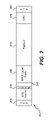
- FIG. 2 indicates one example of an EISL frame.
- the size, sequence and functionality of the fields within this EISL frame can vary from implementation to implementation. For example, the numbers of bits indicated for each field are different in alternative EISL frames.
- the EISL frame 200 is bounded by start of frame delimiter (“SOF”) 205 an end of frame delimiter (“EOF”) 280 .
- SOF start of frame delimiter
- EEF end of frame delimiter
- These delimiters enable an EISL-capable port to receive frames in a standard format at all times. If an EISL-capable port is not in EISL mode and receives frames in the EISL format, it accepts the frame according to some aspects of the invention. However, the port may not be able to send frames in EISL format.
- EISL header 260 includes VSAN field 240 , which specifies the virtual storage area network number of payload 270 .
- VSAN allows for multiple logical or “virtual” storage area networks to be based upon a single physical storage area network. Accordingly, VSAN field 240 of EISL header 260 indicates the virtual storage area network to which this frame belongs.
- MPLS label stack field 265 provides a common forwarding mechanism for both FC and Ethernet frames.
- Cyclic redundancy check (“CRC”) field 275 is used for error detection.
- Exchange Link Parameter (“ELP”) protocol is an existing FC protocol that is used for communication with E ports.
- Exchange Switch Capability (“ESC”) protocol is an existing FC protocol that is used for communication between E ports.
- a new protocol known herein as exchange peer protocol (“EPP”)
- EPP exchange peer protocol
- the EPP protocol is used after the ESC protocol.
- ESC protocol is used to determine if a network device is capable of performing EPP protocol exchange.
- the EPP protocol may be used, for example, to determine the port VSAN of a peer port of a network device or to determine whether the peer port is configurable for supporting EISL.
- the peer port is referred to as a “trunking port”.
- FIG. 3 illustrates a simplified version of an EISL frame.
- frame 300 includes EISL header 305 , header 310 and payload 315 .
- Header 310 may be, for example, an FC header or an Ethernet header.
- field 320 is a field of payload 315 .
- field 320 is a service access point (“SAP”) field, which is a part of a fiber channel frame that is reserved for services that may be defined by a client.
- SAP service access point
- Field 320 is an SAP field used for encoding EPP.
- field 320 is an EPP header and payload 315 includes an EPP payload, which will be described in more detail below.
- FIG. 4 illustrates stack 400 according to some embodiments of the present invention.
- Stack 400 includes physical layer 405 .
- FC 2 layer 410 For simplicity, all of the fiber channel layers are illustrated as a single layer, FC 2 layer 410 .
- Switch Interlink Services (“SW_ILS”) layer 415 provides functionality for ELP 420 and ESC 425 , according to the standard FC format. Layer 415 also provides a mechanism for vendors to add their own protocols, such as EPP_ILS 430 in this example.
- the EPP protocol frames exchanged according to SW_ILS service specification are called EPP_ILS frames.
- ELS Extended Link Services
- FIG. 5 is a flow diagram that depicts an exchange of information between two E ports according to some aspects of the present invention.
- E port A may be, for example, port 160 of FIG. 1 and E port B may be, for example, E port 170 of FIG. 1 .
- one or both ports are F ports and may exchange frames using, for example, ELS format.
- the information exchanged in section 505 of FIG. 5 represents the detection phase of EPP, wherein the EPP capability of an attached peer port is detected.
- Detection phase 505 is performed using ELP and ESC according to one implementation of this method.
- Area 510 represents the SYNC phase of EPP, wherein configuration information of interest to the peer port is exchanged.
- the configuration information is exchanged in time-length-value (“TLV”) format, which will be described below with reference to FIG. 5A .
- area 515 represents the commit phase of EPP.
- the results of the exchange of configuration information that took place during the SYNC phase are applied to hardware and/or software of the peer ports, as needed.
- the EPP detection phase 505 uses ESC service exchanges during E-port initialization.
- the originator port can publish the protocol/services supported by the originator port.
- the peer port is required to respond with the service it agrees to work with or it can respond as “command unsupported.”
- ELP request 525 includes link-level parameters such as buffer-to-buffer credit (indicating how much data can be transmitted from one buffer to another before new credits are required).
- step 530 port B sends information to port A indicating an acceptance of the ELP request.
- step 525 involves the sending of port A's link-level parameters to port B and step 530 involves the sending of port B's link-level parameters to port A.
- step 535 port A sends an acknowledgement to port B. At this time, port A knows port B's link configuration and port B knows port A's link configuration.
- step 540 port A sends other information regarding the configuration of the network device that includes port A.
- port A indicates the services/protocols that port A can support.
- the information will include a vendor string that indicates the particular vendor and model number of the network device and its capabilities.
- step 540 includes the transmission of services/protocols that port A can support in code/service pairs.
- Some codes may be standard FC codes which correspond with standard FC services (e.g., FSPF). However, one such code is a unique code that corresponds with EPP.
- port B sends an acceptance to port A and also sends information regarding the vendor and switch capabilities of the switch associated with port B.
- both port A and port B support EPP. Accordingly, detection phase 505 was successful and in steps 530 and 545 , port B accepted port A's request and ESC information, respectively. However, port B could have rejected either of those requests. Alternatively, port B could have selected a different service if port B did not support EPP.
- exchanges are performed according to an SW_ILS format, as described above.
- port A After determining that port B supports EPP and that port B could be configured to be a trunking port, port A sends an EPP_SYNC_ILS to port B in step 550 and EPP SYNC_ILS phase 510 begins.
- the EPP_SYNC_ILS includes configuration information for use by Port B in configuring itself to be a trunking E port.
- EPP may be used for port VSAN consistency checks without configuring port B as a trunking port.
- FIG. 5A illustrates frame 585 in type-length-value (“TLV”) format, which is a preferred format for data exchanged between ports A and B during SYNC phase 510 .
- Type field 590 encodes how value field 592 is to be interpreted. In other words, type field 590 indicates what kind of value will be encoded in value field 592 .
- Length field 591 indicates the length of value field 592 , e.g., in bytes.
- Value field 592 is a payload that encodes information to be interpreted as specified by type field 590 .
- TLV format is inherently quite flexible, because both the type and length of value field 592 can be varied. However, in other embodiments of the invention, fixed-length frames may be used for the same purpose.
- trunking information is one type of information that may be exchanged during step 550 of SYNC phase 510 .
- trunking configuration information includes admin trunk mode information (administratively configured by the user), which may be “ON,” “OFF” or “AUTO.” “OFF” indicates that the sending port is configured not to operate as a trunking port. “ON” indicates that the sending port can operate as a trunking port if the receiving port does not explicitly prohibit this from happening. “AUTO” indicates that the sending port can operate as a trunking port if the receiving port is configured with trunking mode “ON.”
- FIG. 6 is table that indicates trunk mode negotiation according to some aspects of the present invention. If the sending trunk mode (here, port A) has an admin trunk mode setting of “OFF,” then the sending port will be treated as a non-trunking port. If the admin trunk mode of the sending port is “ON,” the sending port will be treated as a trunking port if the receiving port (here, port B) has an admin trunk mode of “ON” or “AUTO.” If the sending port has an admin trunk mode of “AUTO,” the receiving port must have an admin trunk mode of ON for the sending trunk mode to operate as a trunking port. Otherwise, the receiving port will operate as a normal port.
- step 555 port B sends an acknowledgement to port A.
- step 560 port B sends its own configuration information, which may include trunking configuration information as described above, to port A.
- ports A and B may exchange VSAN list information during SYNC phase 510 .
- the exchange of VSAN list information will now be explained with reference to FIG. 7 .
- ports A and B exchange bit maps that indicate which VSANs to allow.
- port A sends bit map 705 to port B in which bits 1 through 5 have a value of “1,” indicating that VSANs 1 through 5 should be allowed.
- Port B sends bit map 710 indicating that VSANs 4 through 8 should be allowed.
- the bit maps indicate the status of more (or less) than 8 VSANs and include a correspondingly greater (or smaller) number of bits.
- intersection bit map 715 indicates that VSANs 4 and 5 are both allowed.
- the intersection bit map is computed at the end of the EPP_SYNC phase. In other embodiments of the present invention, the intersection bit map is computed at other times. However, this process should occur prior to the beginning of the commit phase.
- VSANs 4 and 5 are known as “operational VSANs” on the link between port A and port B.
- the configuration information exchanged during SYNC phase 510 includes port VSAN information.
- port VSAN information is particularly important when the ports are functioning as non-trunking ports. If ports are functioning as trunking ports, the EISL header will contain a VSAN number indicating the VSAN to which the frame belongs.
- the ports are not functioning as trunking ports, there will be no EISL header and consequently no VSAN number. If a port is not trunking, frames will be transmitted in the native FC format, not in EISL format. However, a VSAN will be implicitly associated with each frame. This VSAN is the port VSAN of the receiving port.
- every E port has a port VSAN number equal to 1.
- various port VSAN numbers may be assigned. If there is a mismatch between port VSAN numbers, various actions may take place according to various aspects of the present invention. According to some such aspects, a system administrator would be notified if, for example, a port having a port VSAN number of 1 sent a packet to a port having a port VSAN number of 2. According to other aspects of the invention, one or more of the ports would be brought down in the event of such a port VSAN mismatch.
- port A knows the configuration of port B and port B knows the configuration of port A.
- port A sends an acknowledgement to port B indicating that it has received port B's EPP_SYNC configuration information. Then, the EPP_SYNC phase of the process has concluded. On completion of SYNC phase 510 , ports A and B will evaluate the configuration information that needs to be applied.
- ports A and B are configured to become trunking E ports. Accordingly, prior to EPP_Commit phase 515 , port B is configured to be a trunking E port in programming step 568 .
- programming step 568 involves hardware programming necessary for supporting trunking mode operation and the preparation of EISL frames. In one instance, when the port is enabled for trunking mode, all frames are transmitted in EISL format.
- step 568 the EPP_Commit phase commences in step 570 by the sending of an EPP_Commit request from port B to port A.
- port A receives the EPP_Commit request
- port A performs its own programming operation in step 572 , which is parallel to the programming step 568 of port B: according to some aspects of the invention, programming step 572 involves hardware programming necessary for supporting trunking mode operation and the preparation of EISL frames. In one instance, when the port is enabled for trunking mode, all frames are transmitted in EISL format. Then, in step 575 , port A sends an SW_ACC to port B, indicating that port A has completed its programming step.
- step 580 port B sends an acknowledgement to port A indicating receipt of the SW_ACC sent in step 575 and completion of the EPP commit exchange on its side. At this time, port A has completed the EPP commit exchange. In the present example, this means that ports A and B are now configured for trunk mode operation
- an operator may decide to reconfigure some aspect of the ports. For example, the VSAN number may change on one or both of the ports and a new intersection bit map would need to be computed. If this is the case, the foregoing process need not go back through the ELP and ESC phases, but may proceed directly to the EPP_SYNC and EPP_Commit phases.
- step 750 a network administrator changes the local admin trunk mode of port A from “AUTO” to “ON.”
- step 755 the EPP SYNC process begins with a parallel to step 550 of FIG. 5 , in which the new local admin trunk mode of port A is transmitted to port B.
- step 760 port B sends an “ACK” to port A.
- the peer admin trunk mode (of port B) remains set to “AUTO.” Consequently, port B sends its peer admin trunk mode to port A in step 765 , port A responds with an “ACK” in step 770 and both ports change their operational trunk mode to T (trunking) in step 775 .
- the necessary EPP commit programming for trunking operation is performed in step 780 .
- FIG. 8 is a flow chart that depicts the process flow of an EPP method from the initiating port's perspective, according to one aspect of the present invention.
- the first step is step 805 , the ready state.
- step 810 an EPP_SYNC request is sent to the receiving port.
- step 815 the initiating port requests an acceptance from the receiving port for the EPP_SYNC request. If the response is received within a predetermined time, the response is evaluated in step 820 . If the response is not received within the predetermined time, the method proceeds to step 830 and the initiating port enters a retry waiting state.
- port A determines whether to accept the EPP_SYNC request from port B. If port A does accept the EPP_SYNC request from port B, the process continues to step 910 of FIG. 9 , which is described below. If port A does not accept the EPP_SYNC request from port B, port A sends a rejection (e.g., an “SW_RJT”) to port B in step 817 . Then, the process returns to step 815 .
- a rejection e.g., an “SW_RJT”
- step 835 it is determined whether the retry count or time is exceeded. If this retry count is exceeded, a failure will be reported and the system will return to a ready state. If the retry count is not exceeded, the EPP_SYNC request will be sent once again in step 810 and the process will proceed from step 810 .
- step 820 if the response is determined to be acceptable, the method proceeds to step 825 , where the system waits for an EPP_Commit state. If the response is determined not to be acceptable in step 820 , an SW_RJT response is sent to the receiving port and the initiating port returns to the ready state of step 805 .
- step 825 If an EPP_Commit is received by the initiating port in step 825 , then the process continues to step 840 , wherein hardware programming is performed on the initiating port. In step 845 , it is determined whether the hardware programming is completed. If not, the method proceeds to step 855 , wherein the hardware programming step is reported and the system enters the retry condition of step 830 . If the hardware programming is a success, the method proceeds to step 850 and an SW_ACC response for the EPP_Commit is transmitted to the receiving port.
- step 860 the initiating port waits for an acknowledgement from the receiving port. If the acknowledgement is not received within a predetermined time, then the process proceeds to step 855 . If the acknowledgement is received within the predetermined time, the initiating port returns to the steady state of step 805 .
- FIG. 9 indicates the EPP process from the perspective of the receiving port.
- the receiving port is in a ready state.
- an SW_ACC is sent to the initiating port for the EPP_SYNC.
- the receiving port waits for an acknowledgement for the SW_ACC response. If this response is not received within a predetermined time, there is a timeout and the receiving port returns to the ready state of step 905 . If the acknowledgement is received within the predetermined, the method proceeds to step 920 and hardware programming is performed on the receiving port. In 925 it is determined whether the hardware programming is completed. If not, a failure report is made in step 930 and the receiving port returns to a ready state in step 905 . If the hardware programming is done, the method proceeds to step 935 and an EPP_Commit is sent to the initiating port.
- step 940 the receiving port waits for an SW_ACC for the EPP_Commit that it has sent to the initiating port. If no such response is received within a predetermined time, the process proceeds to step 930 and a failure is reported. The receiving port then returns to the ready state of step 905 . If a response is received during the predetermined time, then the method proceeds to step 945 and the response is evaluated. If the response is determined to be acceptable, a success is notified. In step 950 , if the response is not determined to be acceptable, an error is reported and the system returns to the ready state of 905 .
- FIG. 10 indicates the components, values and sizes of EPP header fields according to some embodiments of the present invention. Other embodiments may have more or fewer fields. Moreover, the fields may have lengths other than those depicted in FIG. 10 .
- the command identifier field indicates values chosen from a range of vendor specific command identifiers.
- the command identifier may indicate, for example, an EPP request, an SW_RJT (reject) or an SW_ACC (accept).
- the value of the command ID is 0X71000000.
- the revision field identifies the revision of the EPP service. For the first revision, the value is 1. The revision number should be changed every time there is a change in the EPP header.
- EPP uses a two-phase mechanism to establish the operating environment.
- the first phase is the synchronizing phase (EPP_SYNC), where the configuration information on both sides is synchronized.
- the second phase is the commit phase (EPP_COMMIT), where the actual hardware programming is performed.
- the EPP command code field is used to identify whether the EPP request sequence is from the EPP_SYNC phase or the EPP_COMMIT phase.
- the session field is used to identify a particular session on the side that initiated the EPP request sequence. In some cases of error or failure, EPP will retry its protocol exchange. The session number will be changed for each retry of the EPP operation. This feature helps identify stale sessions.
- the worldwide name indicates the WWN of the network device to which the port belongs. According to some aspects of the present invention, the WWN information is used for resolving “collisions” of simultaneous EPP_SYNC requests.
- the payload length field is used to identify the total length of the payload, including the EPP header.
- the reserved field is reserved for future use.
- the techniques of the present invention may be implemented on software and/or hardware.
- they can be implemented in an operating system kernel, in a separate user process, in a library package bound into network applications, on a specially constructed machine, or on a network interface card.
- the technique of the present invention is implemented in software such as an operating system or in an application running on an operating system.
- a software or software/hardware hybrid implementation of the techniques of this invention may be implemented on a general-purpose programmable machine selectively activated or reconfigured by a computer program stored in memory.
- a programmable machine may be a network device designed to handle network traffic, such as, for example, a router or a switch.
- Such network devices may have multiple network interfaces including frame relay and ISDN interfaces, for example. Specific examples of such network devices include routers and switches.
- the methods of this invention may be implemented in specially configured network devices such as the MDS 9000 family of switches manufactured by Cisco Systems, Inc. of San Jose, Calif. A generalized architecture for some such machines will appear from the description given below.
- the techniques of this invention may be implemented on a general-purpose network host machine such as a personal computer or workstation.
- the invention may be at least partially implemented on a card (e.g., an interface card) for a network device or a general-purpose computing device.
- a network device 1160 suitable for implementing the techniques of the present invention includes a master central processing unit (CPU) 1162 , interfaces 1168 , and a bus 1167 (e.g., a PCI bus).
- the CPU 1162 may be responsible for implementing specific functions associated with the functions of a desired network device.
- the CPU 1162 may be responsible for analyzing packets, encapsulating packets, and forwarding packets for transmission to a set-top box.
- the CPU 1162 preferably accomplishes all these functions under the control of software including an operating system (e.g. Windows NT), and any appropriate applications software.
- an operating system e.g. Windows NT
- CPU 1162 may include one or more processors 1163 such as a processor from the Motorola family of microprocessors or the MIPS family of microprocessors. In an alternative embodiment, processor 1163 is specially designed hardware for controlling the operations of network device 1160 . In a specific embodiment, a memory 1161 (such as non-volatile RAM and/or ROM) also forms part of CPU 1162 . However, there are many different ways in which memory could be coupled to the system. Memory block 1161 may be used for a variety of purposes such as, for example, caching and/or storing data, programming instructions, etc.
- the interfaces 1168 are typically provided as interface cards (sometimes referred to as “line cards”). Generally, they control the sending and receiving of data packets over the network and sometimes support other peripherals used with the network device 1160 .
- the interfaces that may be provided are Ethernet interfaces, frame relay interfaces, cable interfaces, DSL interfaces, token ring interfaces, and the like.
- various very high-speed interfaces may be provided, such as fast Ethernet interfaces, Gigabit Ethernet interfaces, ATM interfaces, HSSI interfaces, POS interfaces, FDDI interfaces, ASI interfaces, DHEI interfaces and the like.
- these interfaces may include ports appropriate for communication with the appropriate media. In some cases, they may also include an independent processor and, in some instances, volatile RAM.
- the independent processors may control such communications intensive tasks as packet switching, media control and management. By providing separate processors for the communications intensive tasks, these interfaces allow the master microprocessor 1162 to efficiently perform routing computations, network diagnostics, security functions, etc.
- FIG. 11 illustrates one specific network device of the present invention
- it is by no means the only network device architecture on which the present invention can be implemented.
- an architecture having a single processor that handles communications as well as routing computations, etc. is often used.
- other types of interfaces and media could also be used with the network device.
- the network device may employ one or more memories or memory modules (such as, for example, memory block 1165 ) configured to store data, program instructions for the general-purpose network operations and/or other information relating to the functionality of the techniques described herein.
- the program instructions may control the operation of an operating system and/or one or more applications, for example.
- the present invention relates to machine-readable media that include program instructions, state information, etc. for performing various operations described herein.
- machine-readable media include, but are not limited to, magnetic media such as hard disks, floppy disks, and magnetic tape; optical media such as CD-ROM disks; magneto-optical media; and hardware devices that are specially configured to store and perform program instructions, such as read-only memory devices (ROM) and random access memory (RAM).
- ROM read-only memory devices
- RAM random access memory
- the invention may also be embodied in a carrier wave traveling over an appropriate medium such as airwaves, optical lines, electric lines, etc.
- program instructions include both machine code, such as produced by a compiler, and files containing higher level code that may be executed by the computer using an interpreter.
Abstract
Description
Claims (29)
Priority Applications (7)
| Application Number | Priority Date | Filing Date | Title |
|---|---|---|---|
| US10/430,491 US7433326B2 (en) | 2002-11-27 | 2003-05-05 | Methods and devices for exchanging peer parameters between network devices |
| PCT/US2003/036452 WO2004051938A2 (en) | 2002-11-27 | 2003-11-12 | Methods and devices for exchanging peer parameters between network devices |
| CA002505055A CA2505055A1 (en) | 2002-11-27 | 2003-11-12 | Methods and devices for exchanging peer parameters between network devices |
| CN2003801044666A CN1717910B (en) | 2002-11-27 | 2003-11-12 | Methods and devices for exchanging peer parameters between network devices |
| EP03789766.7A EP1566040B1 (en) | 2002-11-27 | 2003-11-12 | Method and device for exchanging peer parameters between network devices |
| AU2003296301A AU2003296301A1 (en) | 2002-11-27 | 2003-11-12 | Methods and devices for exchanging peer parameters between network devices |
| US12/202,004 US8605624B2 (en) | 2002-11-27 | 2008-08-29 | Methods and devices for exchanging peer parameters between network devices |
Applications Claiming Priority (2)
| Application Number | Priority Date | Filing Date | Title |
|---|---|---|---|
| US42989702P | 2002-11-27 | 2002-11-27 | |
| US10/430,491 US7433326B2 (en) | 2002-11-27 | 2003-05-05 | Methods and devices for exchanging peer parameters between network devices |
Related Child Applications (1)
| Application Number | Title | Priority Date | Filing Date |
|---|---|---|---|
| US12/202,004 Continuation US8605624B2 (en) | 2002-11-27 | 2008-08-29 | Methods and devices for exchanging peer parameters between network devices |
Publications (2)
| Publication Number | Publication Date |
|---|---|
| US20040100910A1 US20040100910A1 (en) | 2004-05-27 |
| US7433326B2 true US7433326B2 (en) | 2008-10-07 |
Family
ID=32329322
Family Applications (2)
| Application Number | Title | Priority Date | Filing Date |
|---|---|---|---|
| US10/430,491 Active 2025-12-08 US7433326B2 (en) | 2002-11-27 | 2003-05-05 | Methods and devices for exchanging peer parameters between network devices |
| US12/202,004 Active 2024-08-30 US8605624B2 (en) | 2002-11-27 | 2008-08-29 | Methods and devices for exchanging peer parameters between network devices |
Family Applications After (1)
| Application Number | Title | Priority Date | Filing Date |
|---|---|---|---|
| US12/202,004 Active 2024-08-30 US8605624B2 (en) | 2002-11-27 | 2008-08-29 | Methods and devices for exchanging peer parameters between network devices |
Country Status (6)
| Country | Link |
|---|---|
| US (2) | US7433326B2 (en) |
| EP (1) | EP1566040B1 (en) |
| CN (1) | CN1717910B (en) |
| AU (1) | AU2003296301A1 (en) |
| CA (1) | CA2505055A1 (en) |
| WO (1) | WO2004051938A2 (en) |
Cited By (39)
| Publication number | Priority date | Publication date | Assignee | Title |
|---|---|---|---|---|
| US20060092932A1 (en) * | 2004-11-01 | 2006-05-04 | Cisco Technology, Inc. | Trunking for fabric ports in fibre channel switches and attached devices |
| US20070223681A1 (en) * | 2006-03-22 | 2007-09-27 | Walden James M | Protocols for connecting intelligent service modules in a storage area network |
| US20070237163A1 (en) * | 2001-07-23 | 2007-10-11 | Broadcom Corporation | Multiple virtual channels for use in network devices |
| US20080316942A1 (en) * | 2002-11-27 | 2008-12-25 | Cisco Technology, Inc. | Methods and devices for exchanging peer parameters between network devices |
| US20090141657A1 (en) * | 2003-06-26 | 2009-06-04 | Cisco Systems, Inc. | FIBRE CHANNEL SWITCH THAT ENABLES END DEVICES IN DIFFERENT FABRICS TO COMMUNICATE WITH ONE ANOTHER WHILE RETAINING THEIR UNIQUE FIBRE CHANNEL DOMAIN_IDs |
| US7684347B2 (en) | 2004-12-23 | 2010-03-23 | Solera Networks | Method and apparatus for network packet capture distributed storage system |
| US20100104280A1 (en) * | 2008-10-24 | 2010-04-29 | Carlson Scott M | Fibre channel framing and signaling optional header for ethernet fabric configuration information |
| US7830809B2 (en) | 2002-06-12 | 2010-11-09 | Cisco Technology, Inc. | Methods and apparatus for characterizing a route in a fibre channel fabric |
| US7885256B1 (en) * | 2003-05-30 | 2011-02-08 | Symantec Operating Corporation | SAN fabric discovery |
| US20110082940A1 (en) * | 2009-10-02 | 2011-04-07 | Michael Peter Montemurro | Methods and apparatus to establish peer-to-peer communications |
| US8462790B2 (en) | 2002-04-01 | 2013-06-11 | Cisco Technology, Inc. | Label switching in fibre channel networks |
| US8521732B2 (en) | 2008-05-23 | 2013-08-27 | Solera Networks, Inc. | Presentation of an extracted artifact based on an indexing technique |
| US8625642B2 (en) | 2008-05-23 | 2014-01-07 | Solera Networks, Inc. | Method and apparatus of network artifact indentification and extraction |
| US8666985B2 (en) | 2011-03-16 | 2014-03-04 | Solera Networks, Inc. | Hardware accelerated application-based pattern matching for real time classification and recording of network traffic |
| US20140086054A1 (en) * | 2010-07-19 | 2014-03-27 | Cisco Technology, Inc. | Mitigating the effects of congested interfaces on a fabric |
| US8750320B2 (en) | 1997-01-23 | 2014-06-10 | Broadcom Corporation | Fibre channel arbitrated loop bufferless switch circuitry to increase bandwidth without significant increase in cost |
| US8798091B2 (en) | 1998-11-19 | 2014-08-05 | Broadcom Corporation | Fibre channel arbitrated loop bufferless switch circuitry to increase bandwidth without significant increase in cost |
| US8849991B2 (en) | 2010-12-15 | 2014-09-30 | Blue Coat Systems, Inc. | System and method for hypertext transfer protocol layered reconstruction |
| US20150188824A1 (en) * | 2013-01-14 | 2015-07-02 | International Business Machines Corporation | Link aggregation (lag) information exchange protocol |
| US9853873B2 (en) | 2015-01-10 | 2017-12-26 | Cisco Technology, Inc. | Diagnosis and throughput measurement of fibre channel ports in a storage area network environment |
| US10140172B2 (en) | 2016-05-18 | 2018-11-27 | Cisco Technology, Inc. | Network-aware storage repairs |
| US10178048B2 (en) | 2014-03-19 | 2019-01-08 | International Business Machines Corporation | Exchange switch protocol version in a distributed switch environment |
| US10222986B2 (en) | 2015-05-15 | 2019-03-05 | Cisco Technology, Inc. | Tenant-level sharding of disks with tenant-specific storage modules to enable policies per tenant in a distributed storage system |
| US10243823B1 (en) | 2017-02-24 | 2019-03-26 | Cisco Technology, Inc. | Techniques for using frame deep loopback capabilities for extended link diagnostics in fibre channel storage area networks |
| US10254991B2 (en) | 2017-03-06 | 2019-04-09 | Cisco Technology, Inc. | Storage area network based extended I/O metrics computation for deep insight into application performance |
| US10303534B2 (en) | 2017-07-20 | 2019-05-28 | Cisco Technology, Inc. | System and method for self-healing of application centric infrastructure fabric memory |
| US10404596B2 (en) | 2017-10-03 | 2019-09-03 | Cisco Technology, Inc. | Dynamic route profile storage in a hardware trie routing table |
| US10545914B2 (en) | 2017-01-17 | 2020-01-28 | Cisco Technology, Inc. | Distributed object storage |
| US10585830B2 (en) | 2015-12-10 | 2020-03-10 | Cisco Technology, Inc. | Policy-driven storage in a microserver computing environment |
| US10664169B2 (en) | 2016-06-24 | 2020-05-26 | Cisco Technology, Inc. | Performance of object storage system by reconfiguring storage devices based on latency that includes identifying a number of fragments that has a particular storage device as its primary storage device and another number of fragments that has said particular storage device as its replica storage device |
| US10713203B2 (en) | 2017-02-28 | 2020-07-14 | Cisco Technology, Inc. | Dynamic partition of PCIe disk arrays based on software configuration / policy distribution |
| US10778765B2 (en) | 2015-07-15 | 2020-09-15 | Cisco Technology, Inc. | Bid/ask protocol in scale-out NVMe storage |
| US10826829B2 (en) | 2015-03-26 | 2020-11-03 | Cisco Technology, Inc. | Scalable handling of BGP route information in VXLAN with EVPN control plane |
| US10872056B2 (en) | 2016-06-06 | 2020-12-22 | Cisco Technology, Inc. | Remote memory access using memory mapped addressing among multiple compute nodes |
| US10942666B2 (en) | 2017-10-13 | 2021-03-09 | Cisco Technology, Inc. | Using network device replication in distributed storage clusters |
| US11102291B2 (en) | 2017-05-04 | 2021-08-24 | Amazon Technologies, Inc. | Coordinating inter-region operations in provider network environments |
| US11563695B2 (en) | 2016-08-29 | 2023-01-24 | Cisco Technology, Inc. | Queue protection using a shared global memory reserve |
| US11588783B2 (en) | 2015-06-10 | 2023-02-21 | Cisco Technology, Inc. | Techniques for implementing IPV6-based distributed storage space |
| US11770364B2 (en) | 2013-12-17 | 2023-09-26 | Amazon Technologies, Inc. | Private network peering in virtual network environments |
Families Citing this family (12)
| Publication number | Priority date | Publication date | Assignee | Title |
|---|---|---|---|---|
| US7599360B2 (en) * | 2001-12-26 | 2009-10-06 | Cisco Technology, Inc. | Methods and apparatus for encapsulating a frame for transmission in a storage area network |
| US7406034B1 (en) | 2002-04-01 | 2008-07-29 | Cisco Technology, Inc. | Methods and apparatus for fibre channel frame delivery |
| US7593324B2 (en) * | 2004-10-25 | 2009-09-22 | Cisco Technology, Inc. | Graceful port shutdown protocol for fibre channel interfaces |
| US7693516B2 (en) * | 2004-12-28 | 2010-04-06 | Vtech Telecommunications Limited | Method and system for enhanced communications between a wireless terminal and access point |
| US7649844B2 (en) * | 2004-12-29 | 2010-01-19 | Cisco Technology, Inc. | In-order fibre channel packet delivery |
| US7484021B2 (en) * | 2005-10-27 | 2009-01-27 | Cisco Technology, Inc. | Technique for implementing virtual fabric membership assignments for devices in a storage area network |
| US8374502B2 (en) * | 2009-02-27 | 2013-02-12 | Futurewei Technologies, Inc. | Open shortest path first extensions in support of wavelength switched optical networks |
| US7948920B2 (en) * | 2009-03-03 | 2011-05-24 | Cisco Technology, Inc. | Trunking with port aggregation for fabric ports in a fibre channel fabric and attached devices |
| CN101582892B (en) * | 2009-06-19 | 2011-12-21 | 杭州华三通信技术有限公司 | Link negotiation method based on fiber channel aggregate port and device |
| CN101645896B (en) * | 2009-09-04 | 2012-06-06 | 杭州华三通信技术有限公司 | Attribute propagation method based on fiber channel network and switch system |
| CN104079424B (en) * | 2013-03-29 | 2017-07-11 | 国际商业机器公司 | For the apparatus and method of asymmetric link polymerization |
| WO2016204777A1 (en) * | 2015-06-19 | 2016-12-22 | Hewlett Packard Enterprise Development LP. | Network communications |
Citations (99)
| Publication number | Priority date | Publication date | Assignee | Title |
|---|---|---|---|---|
| US5428471A (en) | 1992-07-30 | 1995-06-27 | Alcatel Network Systems, Inc. | Fail-safe automatic shut-down apparatus and method for high output power optical communications system |
| US5506838A (en) | 1994-12-29 | 1996-04-09 | Emc Corporation | Packet propagation and dynamic route discovery apparatus and techniques |
| US5617421A (en) | 1994-06-17 | 1997-04-01 | Cisco Systems, Inc. | Extended domain computer network using standard links |
| US5675741A (en) | 1994-10-25 | 1997-10-07 | Cabletron Systems, Inc. | Method and apparatus for determining a communications path between two nodes in an Internet Protocol (IP) network |
| US5682479A (en) | 1995-05-05 | 1997-10-28 | Silicon Graphics, Inc. | System and method for network exploration and access |
| US5708659A (en) | 1993-10-20 | 1998-01-13 | Lsi Logic Corporation | Method for hashing in a packet network switching system |
| US5740171A (en) | 1996-03-28 | 1998-04-14 | Cisco Systems, Inc. | Address translation mechanism for a high-performance network switch |
| US5740159A (en) | 1996-05-23 | 1998-04-14 | Northern Telecom Limited | Loopback mechanism for frame relay OAM |
| US5742604A (en) | 1996-03-28 | 1998-04-21 | Cisco Systems, Inc. | Interswitch link mechanism for connecting high-performance network switches |
| US5764636A (en) | 1996-03-28 | 1998-06-09 | Cisco Technology, Inc. | Color blocking logic mechanism for a high-performance network switch |
| US5809285A (en) | 1995-12-21 | 1998-09-15 | Compaq Computer Corporation | Computer system having a virtual drive array controller |
| US5818603A (en) * | 1996-03-29 | 1998-10-06 | Ricoh Company, Ltd. | Method and system for controlling and communicating with machines using multiple communication formats |
| US5819112A (en) | 1995-09-08 | 1998-10-06 | Microsoft Corporation | Apparatus for controlling an I/O port by queuing requests and in response to a predefined condition, enabling the I/O port to receive the interrupt requests |
| US5862125A (en) | 1995-06-07 | 1999-01-19 | Mci Communication Corporation | Automated restoration of unrestored link and nodal failures |
| US5959972A (en) | 1997-05-27 | 1999-09-28 | 3Com Corporation | Method of port/link redundancy in an ATM switch |
| US5964841A (en) | 1997-03-03 | 1999-10-12 | Cisco Technology, Inc. | Technique for handling forwarding transients with link state routing protocol |
| US5999930A (en) | 1996-08-02 | 1999-12-07 | Hewlett-Packard Company | Method and apparatus for distributed control of a shared storage volume |
| US6035105A (en) | 1996-01-02 | 2000-03-07 | Cisco Technology, Inc. | Multiple VLAN architecture system |
| US6046985A (en) * | 1996-04-10 | 2000-04-04 | International Business Machines Corporation | Communication system with exchange of capability information |
| US6101497A (en) | 1996-05-31 | 2000-08-08 | Emc Corporation | Method and apparatus for independent and simultaneous access to a common data set |
| US6160813A (en) | 1997-03-21 | 2000-12-12 | Brocade Communications Systems, Inc. | Fibre channel switching system and method |
| US6188694B1 (en) | 1997-12-23 | 2001-02-13 | Cisco Technology, Inc. | Shared spanning tree protocol |
| US6188668B1 (en) | 1998-05-01 | 2001-02-13 | Emulex Corporation | Automatic isolation in loops |
| US6202135B1 (en) | 1996-12-23 | 2001-03-13 | Emc Corporation | System and method for reconstructing data associated with protected storage volume stored in multiple modules of back-up mass data storage facility |
| US6205488B1 (en) | 1998-11-13 | 2001-03-20 | Nortel Networks Limited | Internet protocol virtual private network realization using multi-protocol label switching tunnels |
| US6209059B1 (en) | 1997-09-25 | 2001-03-27 | Emc Corporation | Method and apparatus for the on-line reconfiguration of the logical volumes of a data storage system |
| US6208649B1 (en) | 1998-03-11 | 2001-03-27 | Cisco Technology, Inc. | Derived VLAN mapping technique |
| US6208623B1 (en) | 1998-04-13 | 2001-03-27 | 3Com Corporation | Method of combining PNNI and E-IISP in an asynchronous transfer mode network |
| US6226771B1 (en) | 1998-12-14 | 2001-05-01 | Cisco Technology, Inc. | Method and apparatus for generating error detection data for encapsulated frames |
| US6260120B1 (en) | 1998-06-29 | 2001-07-10 | Emc Corporation | Storage mapping and partitioning among multiple host processors in the presence of login state changes and host controller replacement |
| US6262977B1 (en) | 1998-08-28 | 2001-07-17 | 3Com Corporation | High availability spanning tree with rapid reconfiguration |
| US6266705B1 (en) | 1998-09-29 | 2001-07-24 | Cisco Systems, Inc. | Look up mechanism and associated hash table for a network switch |
| US6269431B1 (en) | 1998-08-13 | 2001-07-31 | Emc Corporation | Virtual storage and block level direct access of secondary storage for recovery of backup data |
| US6269381B1 (en) | 1998-06-30 | 2001-07-31 | Emc Corporation | Method and apparatus for backing up data before updating the data and for restoring from the backups |
| US6295296B1 (en) | 1998-09-08 | 2001-09-25 | Cisco Technology, Inc. | Use of a single data structure for label forwarding and imposition |
| US6295575B1 (en) | 1998-06-29 | 2001-09-25 | Emc Corporation | Configuring vectors of logical storage units for data storage partitioning and sharing |
| US20010049739A1 (en) | 2000-06-02 | 2001-12-06 | Koji Wakayama | Apparatus and method for interworking between MPLS network and non-MPLS network |
| US6330614B1 (en) | 1998-03-20 | 2001-12-11 | Nexabit Networks Llc | Internet and related networks, a method of and system for substitute use of checksum field space in information processing datagram headers for obviating processing speed and addressing space limitations and providing other features |
| US6337861B1 (en) | 1999-02-02 | 2002-01-08 | Cisco Technology, Inc. | Method and apparatus to properly route ICMP messages in a tag-switching network |
| US20020009081A1 (en) | 2000-06-09 | 2002-01-24 | Broadcom Corporation | Gigabit switch with frame forwarding and address learning |
| US6388995B1 (en) | 1997-12-24 | 2002-05-14 | Cisco Technology, Inc. | Method and apparatus for rapidly reconfiguring computers networks executing the spanning tree algorithm |
| US6408001B1 (en) | 1998-10-21 | 2002-06-18 | Lucent Technologies Inc. | Method for determining label assignments for a router |
| US6426952B1 (en) | 1998-09-18 | 2002-07-30 | The United States Of America As Represented By The Secretary Of The Navy | Multi-interface point-to-point switching system (MIPPSS) having an internal universal signal format |
| US20020101868A1 (en) | 2001-01-30 | 2002-08-01 | David Clear | Vlan tunneling protocol |
| US20020110125A1 (en) | 1998-10-23 | 2002-08-15 | David Banks | Method and system for creating and implementing zones in hardware within a fibre channel system |
| US6438612B1 (en) | 1998-09-11 | 2002-08-20 | Ssh Communications Security, Ltd. | Method and arrangement for secure tunneling of data between virtual routers |
| US20020150039A1 (en) | 2001-03-30 | 2002-10-17 | Ezio Valdevit | In-order delivery of frames during topology change |
| US20020152338A1 (en) | 1998-10-14 | 2002-10-17 | Elliott Joseph C. | Method, system and program product for detecting lost sequences within an exchange on fibre channel |
| US20020156924A1 (en) | 2001-04-23 | 2002-10-24 | Moshe Czeiger | Method for communicating between fibre channel systems |
| US20020156918A1 (en) | 2001-04-23 | 2002-10-24 | Brocade Communications Systems, Inc. | Dynamic path selection with in-order delivery within sequence in a communication network |
| US6473421B1 (en) | 1999-03-29 | 2002-10-29 | Cisco Technology, Inc. | Hierarchical label switching across multiple OSPF areas |
| US20020176434A1 (en) | 2001-04-18 | 2002-11-28 | Brocade Communications Systems, Inc. | Fibre channel zoning by logical unit number in hardware |
| US6493349B1 (en) | 1998-11-13 | 2002-12-10 | Nortel Networks Limited | Extended internet protocol virtual private network architectures |
| US20020188754A1 (en) | 2001-04-27 | 2002-12-12 | Foster Michael S. | Method and system for domain addressing in a communications network |
| US20030012204A1 (en) | 2001-07-11 | 2003-01-16 | Sancastle Technologies, Ltd | Extension of fibre channel addressing |
| US20030016624A1 (en) | 1998-05-04 | 2003-01-23 | Bare Ballard C. | Path recovery on failure in load balancing switch protocols |
| US6529963B1 (en) | 1998-12-29 | 2003-03-04 | Lsi Logic Corporation | Methods and apparatus for interconnecting independent fibre channel fabrics |
| US6532212B1 (en) | 2001-09-25 | 2003-03-11 | Mcdata Corporation | Trunking inter-switch links |
| US20030101239A1 (en) | 2001-11-27 | 2003-05-29 | Takeshi Ishizaki | Storage device with VLAN support |
| US20030107987A1 (en) | 2001-12-07 | 2003-06-12 | Kinstler Gary A. | Reconfiguration system for a communication network |
| US20030118053A1 (en) * | 2001-12-26 | 2003-06-26 | Andiamo Systems, Inc. | Methods and apparatus for encapsulating a frame for transmission in a storage area network |
| US20030145116A1 (en) | 2002-01-24 | 2003-07-31 | Andrew Moroney | System for communication with a storage area network |
| US6604407B2 (en) | 2001-04-03 | 2003-08-12 | Denso Corporation | Leak check apparatus for fuel vapor purge system |
| US20030163727A1 (en) * | 2002-01-31 | 2003-08-28 | Brocade Communications Systems, Inc. | Network security through configuration servers in the fabric environment |
| US20030189929A1 (en) * | 2002-04-04 | 2003-10-09 | Fujitsu Limited | Electronic apparatus for assisting realization of storage area network system |
| US6661773B1 (en) | 1999-06-07 | 2003-12-09 | Intel Corporation | Method for detection of stale cells following route changes in a data communication |
| US6674760B1 (en) | 1999-09-28 | 2004-01-06 | Extreme Networks, Inc. | Method and system for implementing end-to-end QoS in packet-switched networks |
| US6728220B2 (en) | 2001-05-24 | 2004-04-27 | Riverstone Networks, Inc. | Method and system for preventing transmission loops in a label switching domain |
| US6728848B2 (en) | 2001-06-11 | 2004-04-27 | Hitachi, Ltd. | Method and system for backing up storage system data |
| US6775230B1 (en) | 2000-07-18 | 2004-08-10 | Hitachi, Ltd. | Apparatus and method for transmitting frames via a switch in a storage area network |
| US6804776B1 (en) | 1999-09-21 | 2004-10-12 | Cisco Technology, Inc. | Method for universal transport encapsulation for Internet Protocol network communications |
| US6848007B1 (en) | 1999-11-12 | 2005-01-25 | Crossroads Systems, Inc. | System for mapping addresses of SCSI devices between plurality of SANs that can dynamically map SCSI device addresses across a SAN extender |
| US6859435B1 (en) | 1999-10-13 | 2005-02-22 | Lucent Technologies Inc. | Prevention of deadlocks and livelocks in lossless, backpressured packet networks |
| US6879560B1 (en) | 2000-12-08 | 2005-04-12 | At&T Corp. | System and method for limiting congestion over a switch network |
| US6904053B1 (en) | 1997-02-18 | 2005-06-07 | Emulux Design & Manufacturing Corporation | Fibre Channel switching fabric |
| US6915358B2 (en) | 2001-09-24 | 2005-07-05 | Broadcom Corporation | System and method for hardware based reassembly of a fragmented packet |
| US6920154B1 (en) | 2001-12-17 | 2005-07-19 | Supergate Technology Usa, Inc. | Architectures for a modularized data optimization engine and methods therefor |
| US6920133B1 (en) | 2000-06-07 | 2005-07-19 | At&T Corp. | Techniques for introducing in-band network management packets in multi-protocol label switching networks |
| US6947379B1 (en) | 2001-04-03 | 2005-09-20 | Cisco Technology, Inc. | Packet routing to reduce susceptibility to disturbances |
| US6959151B1 (en) | 1999-05-11 | 2005-10-25 | British Telecommunications Public Limited Company | Communication network |
| US6975589B2 (en) | 2000-12-30 | 2005-12-13 | Redback Networks Inc. | Method and apparatus for a hybrid variable rate pipe |
| US7006525B1 (en) | 2000-02-23 | 2006-02-28 | Cypress Semiconductor Corp. | Hybrid data transport scheme over optical networks |
| US7026288B2 (en) | 2000-05-02 | 2006-04-11 | Theravance, Inc. | Pharmaceutical compositions containing a glycopeptide antibiotic and a cyclodextrin |
| US7027406B1 (en) | 1998-04-16 | 2006-04-11 | Avaya Communication Israel Ltd. | Distributed port-blocking method |
| US7054304B2 (en) | 2001-01-19 | 2006-05-30 | Terited International , Inc. | Method and protocol for managing broadband IP services in a layer two broadcast network |
| US7061858B1 (en) * | 2000-08-23 | 2006-06-13 | Cisco Technology, Inc. | High availability architecture for network devices |
| US7072298B2 (en) | 2001-06-13 | 2006-07-04 | Computer Network Technology Corporation | Method and apparatus for rendering a cell-based switch useful for frame based protocols |
| US7082140B1 (en) | 2000-03-17 | 2006-07-25 | Nortel Networks Ltd | System, device and method for supporting a label switched path across a non-MPLS compliant segment |
| US7085846B2 (en) | 2001-12-31 | 2006-08-01 | Maxxan Systems, Incorporated | Buffer to buffer credit flow control for computer network |
| US7155494B2 (en) | 2002-01-09 | 2006-12-26 | Sancastle Technologies Ltd. | Mapping between virtual local area networks and fibre channel zones |
| US7161935B2 (en) | 2002-01-31 | 2007-01-09 | Brocade Communications Stystems, Inc. | Network fabric management via adjunct processor inter-fabric service link |
| US7206288B2 (en) | 2002-06-12 | 2007-04-17 | Cisco Technology, Inc. | Methods and apparatus for characterizing a route in fibre channel fabric |
| US7216158B2 (en) | 2002-01-18 | 2007-05-08 | Bea Systems, Inc. | System, method and interface for controlling server lifecycle |
| US7221652B1 (en) | 2001-12-14 | 2007-05-22 | Applied Micro Circuits Corporation | System and method for tolerating data link faults in communications with a switch fabric |
| US7275103B1 (en) | 2002-12-18 | 2007-09-25 | Veritas Operating Corporation | Storage path optimization for SANs |
| US7302494B2 (en) | 2000-12-21 | 2007-11-27 | Fujitsu Limited | Traffic engineering method and node apparatus using traffic engineering method |
| US7319669B1 (en) | 2002-11-22 | 2008-01-15 | Qlogic, Corporation | Method and system for controlling packet flow in networks |
| US7328260B1 (en) | 2002-06-04 | 2008-02-05 | Symantec Operating Corporation | Mapping discovered devices to SAN-manageable objects using configurable rules |
| US7355983B2 (en) | 2004-02-10 | 2008-04-08 | Cisco Technology, Inc. | Technique for graceful shutdown of a routing protocol in a network |
Family Cites Families (65)
| Publication number | Priority date | Publication date | Assignee | Title |
|---|---|---|---|---|
| US5248471A (en) * | 1987-07-06 | 1993-09-28 | Alliedsignal Inc. | Process for forming fibers |
| US5805924A (en) | 1994-11-08 | 1998-09-08 | Stoevhase; Bent | Method and apparatus for configuring fabrics within a fibre channel system |
| US5619497A (en) | 1994-12-22 | 1997-04-08 | Emc Corporation | Method and apparatus for reordering frames |
| US5872822A (en) | 1995-10-26 | 1999-02-16 | Mcdata Corporation | Method and apparatus for memory sequencing |
| US5959990A (en) | 1996-03-12 | 1999-09-28 | Bay Networks, Inc. | VLAN frame format |
| US5793976A (en) | 1996-04-01 | 1998-08-11 | Gte Laboratories Incorporated | Method and apparatus for performance monitoring in electronic communications networks |
| FR2759518B1 (en) | 1997-02-07 | 1999-04-23 | France Telecom | METHOD AND DEVICE FOR ALLOCATING RESOURCES IN A DIGITAL PACKET TRANSMISSION NETWORK |
| EP0858036A3 (en) | 1997-02-10 | 1999-12-22 | Compaq Computer Corporation | Fibre channel attached storage architecture |
| US6310884B1 (en) | 1998-05-21 | 2001-10-30 | Lsi Logic Corporation | Data transfer method and apparatus that allocate storage based upon a received relative offset |
| US7165152B2 (en) * | 1998-06-30 | 2007-01-16 | Emc Corporation | Method and apparatus for managing access to storage devices in a storage system with access control |
| US6401128B1 (en) | 1998-08-07 | 2002-06-04 | Brocade Communiations Systems, Inc. | System and method for sending and receiving frames between a public device and a private device |
| US6931440B1 (en) | 1999-04-21 | 2005-08-16 | Emc Corporation | Method and apparatus for dynamically determining whether access to a resource connected to a computer has changed and determining how to access the resource with a new identifier |
| US6535489B1 (en) | 1999-05-21 | 2003-03-18 | Advanced Micro Devices, Inc. | Method and apparatus in a network switch for handling link failure and link recovery in a trunked data path |
| WO2001019027A2 (en) | 1999-09-08 | 2001-03-15 | Qualcomm Incorporated | Methods for efficient early protocol detection |
| US6643287B1 (en) | 1999-11-24 | 2003-11-04 | Pluris, Inc. | Apparatus and method for forwarding encapsulated data packets on a network having multiple links between nodes |
| JP2001154929A (en) | 1999-11-29 | 2001-06-08 | Nec Software Shikoku Ltd | Management method and system for substituting path system |
| JP3538707B2 (en) | 2000-02-21 | 2004-06-14 | 株式会社村田製作所 | Silicone rubber curing method and curing device |
| JP4150159B2 (en) | 2000-03-01 | 2008-09-17 | 富士通株式会社 | Transmission path control device, transmission path control method, and medium recording transmission path control program |
| JP4006169B2 (en) | 2000-05-30 | 2007-11-14 | 株式会社日立製作所 | Label switching type packet transfer device |
| AU2001266671A1 (en) | 2000-06-02 | 2001-12-17 | Inrange Technologies Corporation | Address conversion method and device in a fibre channel switch |
| US7046669B1 (en) | 2000-06-28 | 2006-05-16 | Nortel Networks Limited | Communications network |
| US6920153B2 (en) | 2000-07-17 | 2005-07-19 | Nortel Networks Limited | Architecture and addressing scheme for storage interconnect and emerging storage service providers |
| US6847647B1 (en) * | 2000-09-26 | 2005-01-25 | Hewlett-Packard Development Company, L.P. | Method and apparatus for distributing traffic over multiple switched fiber channel routes |
| JP3729051B2 (en) | 2000-10-18 | 2005-12-21 | 日本電気株式会社 | Inter-domain routing apparatus, system and method |
| US20020085493A1 (en) | 2000-12-19 | 2002-07-04 | Rick Pekkala | Method and apparatus for over-advertising infiniband buffering resources |
| US6853641B2 (en) | 2000-12-20 | 2005-02-08 | Nortel Networks Limited | Method of protecting traffic in a mesh network |
| US7076594B2 (en) | 2000-12-22 | 2006-07-11 | Cisco Technology, Inc. | Apparatus and method for preventing one way connectivity loops in a computer network |
| AU2002306495A1 (en) | 2001-02-13 | 2002-08-28 | Candera, Inc. | Storage virtualization and storage management to provide higher level storage services |
| US6708285B2 (en) | 2001-03-15 | 2004-03-16 | Hewlett-Packard Development Company, L.P. | Redundant controller data storage system having system and method for handling controller resets |
| US7260104B2 (en) | 2001-12-19 | 2007-08-21 | Computer Network Technology Corporation | Deferred queuing in a buffered switch |
| US7330892B2 (en) * | 2001-09-07 | 2008-02-12 | Network Appliance, Inc. | High-speed data transfer in a storage virtualization controller |
| US7254111B2 (en) | 2001-10-05 | 2007-08-07 | Samsung Electronics Co., Ltd. | Routing coordination protocol for a massively parallel router architecture |
| US20030084219A1 (en) * | 2001-10-26 | 2003-05-01 | Maxxan Systems, Inc. | System, apparatus and method for address forwarding for a computer network |
| US6766482B1 (en) | 2001-10-31 | 2004-07-20 | Extreme Networks | Ethernet automatic protection switching |
| US7499410B2 (en) * | 2001-12-26 | 2009-03-03 | Cisco Technology, Inc. | Fibre channel switch that enables end devices in different fabrics to communicate with one another while retaining their unique fibre channel domain—IDs |
| US6917986B2 (en) | 2002-01-07 | 2005-07-12 | Corrigent Systems Ltd. | Fast failure protection using redundant network edge ports |
| US7406034B1 (en) | 2002-04-01 | 2008-07-29 | Cisco Technology, Inc. | Methods and apparatus for fibre channel frame delivery |
| US7616637B1 (en) | 2002-04-01 | 2009-11-10 | Cisco Technology, Inc. | Label switching in fibre channel networks |
| US7627693B2 (en) | 2002-06-11 | 2009-12-01 | Pandya Ashish A | IP storage processor and engine therefor using RDMA |
| US7301898B1 (en) | 2002-07-29 | 2007-11-27 | Brocade Communications Systems, Inc. | Credit sharing for fibre channel links with multiple virtual channels |
| KR100433556B1 (en) | 2002-08-08 | 2004-05-31 | 삼성전자주식회사 | Link-state synchronization on Ad-hoc network, method therefore, and data structure therefore |
| US20040085908A1 (en) | 2002-10-31 | 2004-05-06 | Brocade Communications Systems, Inc. | Method and apparatus for managing locking of resources in a cluster by use of a network fabric |
| US7433326B2 (en) | 2002-11-27 | 2008-10-07 | Cisco Technology, Inc. | Methods and devices for exchanging peer parameters between network devices |
| US8060630B1 (en) | 2002-11-27 | 2011-11-15 | Symantec Operating Corporation | Creating and configuring virtual fabrics in storage area networks |
| US8081642B2 (en) * | 2003-01-31 | 2011-12-20 | Brocade Communications Systems, Inc. | Method and apparatus for routing between fibre channel fabrics |
| US7606239B2 (en) * | 2003-01-31 | 2009-10-20 | Brocade Communications Systems, Inc. | Method and apparatus for providing virtual ports with attached virtual devices in a storage area network |
| DE10308323B4 (en) * | 2003-02-26 | 2007-10-11 | Infineon Technologies Ag | Semiconductor chip arrangement with ROM |
| US20040210656A1 (en) | 2003-04-16 | 2004-10-21 | Silicon Graphics, Inc. | Failsafe operation of storage area network |
| US8560627B2 (en) | 2003-05-23 | 2013-10-15 | Alcatel Lucent | Virtual switch for use in fibre channel applications |
| US7512067B2 (en) | 2003-07-21 | 2009-03-31 | Qlogic, Corporation | Method and system for congestion control based on optimum bandwidth allocation in a fibre channel switch |
| US7477655B2 (en) | 2003-07-21 | 2009-01-13 | Qlogic, Corporation | Method and system for power control of fibre channel switches |
| US7630384B2 (en) | 2003-07-21 | 2009-12-08 | Qlogic, Corporation | Method and system for distributing credit in fibre channel systems |
| US7684401B2 (en) | 2003-07-21 | 2010-03-23 | Qlogic, Corporation | Method and system for using extended fabric features with fibre channel switch elements |
| US7447224B2 (en) * | 2003-07-21 | 2008-11-04 | Qlogic, Corporation | Method and system for routing fibre channel frames |
| US20050080903A1 (en) * | 2003-09-30 | 2005-04-14 | Moshe Valenci | Method, system, and program for maintaining a link between two network entities |
| US20080028096A1 (en) * | 2003-10-21 | 2008-01-31 | Henderson Alex E | Transporting fibre channel over ethernet |
| US7443799B2 (en) | 2003-10-31 | 2008-10-28 | Brocade Communication Systems, Inc. | Load balancing in core-edge configurations |
| US20050108444A1 (en) * | 2003-11-19 | 2005-05-19 | Flauaus Gary R. | Method of detecting and monitoring fabric congestion |
| US7983173B2 (en) | 2004-05-10 | 2011-07-19 | Cisco Technology, Inc. | System and method for detecting link failures |
| US20050267965A1 (en) | 2004-05-13 | 2005-12-01 | Ixi Mobile (R&D) Ltd. | Mobile router graceful shutdown system and method |
| US8018936B2 (en) * | 2004-07-19 | 2011-09-13 | Brocade Communications Systems, Inc. | Inter-fabric routing |
| US7593324B2 (en) * | 2004-10-25 | 2009-09-22 | Cisco Technology, Inc. | Graceful port shutdown protocol for fibre channel interfaces |
| US7916628B2 (en) * | 2004-11-01 | 2011-03-29 | Cisco Technology, Inc. | Trunking for fabric ports in fibre channel switches and attached devices |
| US7649844B2 (en) * | 2004-12-29 | 2010-01-19 | Cisco Technology, Inc. | In-order fibre channel packet delivery |
| US7519058B2 (en) * | 2005-01-18 | 2009-04-14 | Qlogic, Corporation | Address translation in fibre channel switches |
-
2003
- 2003-05-05 US US10/430,491 patent/US7433326B2/en active Active
- 2003-11-12 CN CN2003801044666A patent/CN1717910B/en not_active Expired - Fee Related
- 2003-11-12 EP EP03789766.7A patent/EP1566040B1/en not_active Expired - Fee Related
- 2003-11-12 CA CA002505055A patent/CA2505055A1/en not_active Abandoned
- 2003-11-12 AU AU2003296301A patent/AU2003296301A1/en not_active Abandoned
- 2003-11-12 WO PCT/US2003/036452 patent/WO2004051938A2/en not_active Application Discontinuation
-
2008
- 2008-08-29 US US12/202,004 patent/US8605624B2/en active Active
Patent Citations (105)
| Publication number | Priority date | Publication date | Assignee | Title |
|---|---|---|---|---|
| US5428471A (en) | 1992-07-30 | 1995-06-27 | Alcatel Network Systems, Inc. | Fail-safe automatic shut-down apparatus and method for high output power optical communications system |
| US5708659A (en) | 1993-10-20 | 1998-01-13 | Lsi Logic Corporation | Method for hashing in a packet network switching system |
| US5617421A (en) | 1994-06-17 | 1997-04-01 | Cisco Systems, Inc. | Extended domain computer network using standard links |
| US5675741A (en) | 1994-10-25 | 1997-10-07 | Cabletron Systems, Inc. | Method and apparatus for determining a communications path between two nodes in an Internet Protocol (IP) network |
| US5506838A (en) | 1994-12-29 | 1996-04-09 | Emc Corporation | Packet propagation and dynamic route discovery apparatus and techniques |
| US5682479A (en) | 1995-05-05 | 1997-10-28 | Silicon Graphics, Inc. | System and method for network exploration and access |
| US5862125A (en) | 1995-06-07 | 1999-01-19 | Mci Communication Corporation | Automated restoration of unrestored link and nodal failures |
| US5819112A (en) | 1995-09-08 | 1998-10-06 | Microsoft Corporation | Apparatus for controlling an I/O port by queuing requests and in response to a predefined condition, enabling the I/O port to receive the interrupt requests |
| US5809285A (en) | 1995-12-21 | 1998-09-15 | Compaq Computer Corporation | Computer system having a virtual drive array controller |
| US6219699B1 (en) | 1996-01-02 | 2001-04-17 | Cisco Technologies, Inc. | Multiple VLAN Architecture system |
| US6035105A (en) | 1996-01-02 | 2000-03-07 | Cisco Technology, Inc. | Multiple VLAN architecture system |
| US5740171A (en) | 1996-03-28 | 1998-04-14 | Cisco Systems, Inc. | Address translation mechanism for a high-performance network switch |
| US5764636A (en) | 1996-03-28 | 1998-06-09 | Cisco Technology, Inc. | Color blocking logic mechanism for a high-performance network switch |
| US5742604A (en) | 1996-03-28 | 1998-04-21 | Cisco Systems, Inc. | Interswitch link mechanism for connecting high-performance network switches |
| US5818603A (en) * | 1996-03-29 | 1998-10-06 | Ricoh Company, Ltd. | Method and system for controlling and communicating with machines using multiple communication formats |
| US6046985A (en) * | 1996-04-10 | 2000-04-04 | International Business Machines Corporation | Communication system with exchange of capability information |
| US5740159A (en) | 1996-05-23 | 1998-04-14 | Northern Telecom Limited | Loopback mechanism for frame relay OAM |
| US6101497A (en) | 1996-05-31 | 2000-08-08 | Emc Corporation | Method and apparatus for independent and simultaneous access to a common data set |
| US5999930A (en) | 1996-08-02 | 1999-12-07 | Hewlett-Packard Company | Method and apparatus for distributed control of a shared storage volume |
| US6202135B1 (en) | 1996-12-23 | 2001-03-13 | Emc Corporation | System and method for reconstructing data associated with protected storage volume stored in multiple modules of back-up mass data storage facility |
| US6904053B1 (en) | 1997-02-18 | 2005-06-07 | Emulux Design & Manufacturing Corporation | Fibre Channel switching fabric |
| US5964841A (en) | 1997-03-03 | 1999-10-12 | Cisco Technology, Inc. | Technique for handling forwarding transients with link state routing protocol |
| US6597663B1 (en) | 1997-03-03 | 2003-07-22 | Cisco Technology, Inc. | Technique for handling forwarding transients with link state routing protocol |
| US6160813A (en) | 1997-03-21 | 2000-12-12 | Brocade Communications Systems, Inc. | Fibre channel switching system and method |
| US5959972A (en) | 1997-05-27 | 1999-09-28 | 3Com Corporation | Method of port/link redundancy in an ATM switch |
| US6209059B1 (en) | 1997-09-25 | 2001-03-27 | Emc Corporation | Method and apparatus for the on-line reconfiguration of the logical volumes of a data storage system |
| US6188694B1 (en) | 1997-12-23 | 2001-02-13 | Cisco Technology, Inc. | Shared spanning tree protocol |
| US6388995B1 (en) | 1997-12-24 | 2002-05-14 | Cisco Technology, Inc. | Method and apparatus for rapidly reconfiguring computers networks executing the spanning tree algorithm |
| US6208649B1 (en) | 1998-03-11 | 2001-03-27 | Cisco Technology, Inc. | Derived VLAN mapping technique |
| US6330614B1 (en) | 1998-03-20 | 2001-12-11 | Nexabit Networks Llc | Internet and related networks, a method of and system for substitute use of checksum field space in information processing datagram headers for obviating processing speed and addressing space limitations and providing other features |
| US6208623B1 (en) | 1998-04-13 | 2001-03-27 | 3Com Corporation | Method of combining PNNI and E-IISP in an asynchronous transfer mode network |
| US7027406B1 (en) | 1998-04-16 | 2006-04-11 | Avaya Communication Israel Ltd. | Distributed port-blocking method |
| US6188668B1 (en) | 1998-05-01 | 2001-02-13 | Emulex Corporation | Automatic isolation in loops |
| US20030016624A1 (en) | 1998-05-04 | 2003-01-23 | Bare Ballard C. | Path recovery on failure in load balancing switch protocols |
| US6260120B1 (en) | 1998-06-29 | 2001-07-10 | Emc Corporation | Storage mapping and partitioning among multiple host processors in the presence of login state changes and host controller replacement |
| US6295575B1 (en) | 1998-06-29 | 2001-09-25 | Emc Corporation | Configuring vectors of logical storage units for data storage partitioning and sharing |
| US6269381B1 (en) | 1998-06-30 | 2001-07-31 | Emc Corporation | Method and apparatus for backing up data before updating the data and for restoring from the backups |
| US6269431B1 (en) | 1998-08-13 | 2001-07-31 | Emc Corporation | Virtual storage and block level direct access of secondary storage for recovery of backup data |
| US6262977B1 (en) | 1998-08-28 | 2001-07-17 | 3Com Corporation | High availability spanning tree with rapid reconfiguration |
| US6295296B1 (en) | 1998-09-08 | 2001-09-25 | Cisco Technology, Inc. | Use of a single data structure for label forwarding and imposition |
| US6438612B1 (en) | 1998-09-11 | 2002-08-20 | Ssh Communications Security, Ltd. | Method and arrangement for secure tunneling of data between virtual routers |
| US6426952B1 (en) | 1998-09-18 | 2002-07-30 | The United States Of America As Represented By The Secretary Of The Navy | Multi-interface point-to-point switching system (MIPPSS) having an internal universal signal format |
| US6266705B1 (en) | 1998-09-29 | 2001-07-24 | Cisco Systems, Inc. | Look up mechanism and associated hash table for a network switch |
| US20020152338A1 (en) | 1998-10-14 | 2002-10-17 | Elliott Joseph C. | Method, system and program product for detecting lost sequences within an exchange on fibre channel |
| US6408001B1 (en) | 1998-10-21 | 2002-06-18 | Lucent Technologies Inc. | Method for determining label assignments for a router |
| US20020110125A1 (en) | 1998-10-23 | 2002-08-15 | David Banks | Method and system for creating and implementing zones in hardware within a fibre channel system |
| US6205488B1 (en) | 1998-11-13 | 2001-03-20 | Nortel Networks Limited | Internet protocol virtual private network realization using multi-protocol label switching tunnels |
| US6493349B1 (en) | 1998-11-13 | 2002-12-10 | Nortel Networks Limited | Extended internet protocol virtual private network architectures |
| US6226771B1 (en) | 1998-12-14 | 2001-05-01 | Cisco Technology, Inc. | Method and apparatus for generating error detection data for encapsulated frames |
| US6529963B1 (en) | 1998-12-29 | 2003-03-04 | Lsi Logic Corporation | Methods and apparatus for interconnecting independent fibre channel fabrics |
| US6337861B1 (en) | 1999-02-02 | 2002-01-08 | Cisco Technology, Inc. | Method and apparatus to properly route ICMP messages in a tag-switching network |
| US6473421B1 (en) | 1999-03-29 | 2002-10-29 | Cisco Technology, Inc. | Hierarchical label switching across multiple OSPF areas |
| US6959151B1 (en) | 1999-05-11 | 2005-10-25 | British Telecommunications Public Limited Company | Communication network |
| US6661773B1 (en) | 1999-06-07 | 2003-12-09 | Intel Corporation | Method for detection of stale cells following route changes in a data communication |
| US6804776B1 (en) | 1999-09-21 | 2004-10-12 | Cisco Technology, Inc. | Method for universal transport encapsulation for Internet Protocol network communications |
| US6674760B1 (en) | 1999-09-28 | 2004-01-06 | Extreme Networks, Inc. | Method and system for implementing end-to-end QoS in packet-switched networks |
| US6859435B1 (en) | 1999-10-13 | 2005-02-22 | Lucent Technologies Inc. | Prevention of deadlocks and livelocks in lossless, backpressured packet networks |
| US6848007B1 (en) | 1999-11-12 | 2005-01-25 | Crossroads Systems, Inc. | System for mapping addresses of SCSI devices between plurality of SANs that can dynamically map SCSI device addresses across a SAN extender |
| US7006525B1 (en) | 2000-02-23 | 2006-02-28 | Cypress Semiconductor Corp. | Hybrid data transport scheme over optical networks |
| US7082140B1 (en) | 2000-03-17 | 2006-07-25 | Nortel Networks Ltd | System, device and method for supporting a label switched path across a non-MPLS compliant segment |
| US7026288B2 (en) | 2000-05-02 | 2006-04-11 | Theravance, Inc. | Pharmaceutical compositions containing a glycopeptide antibiotic and a cyclodextrin |
| US7079544B2 (en) | 2000-06-02 | 2006-07-18 | Hitachi, Ltd. | Apparatus and method for interworking between MPLS network and non-MPLS network |
| US20010049739A1 (en) | 2000-06-02 | 2001-12-06 | Koji Wakayama | Apparatus and method for interworking between MPLS network and non-MPLS network |
| US6920133B1 (en) | 2000-06-07 | 2005-07-19 | At&T Corp. | Techniques for introducing in-band network management packets in multi-protocol label switching networks |
| US20020009081A1 (en) | 2000-06-09 | 2002-01-24 | Broadcom Corporation | Gigabit switch with frame forwarding and address learning |
| US7046679B2 (en) | 2000-06-09 | 2006-05-16 | Broadcom Corporation | Gigabit switch with frame forwarding and address learning |
| US6775230B1 (en) | 2000-07-18 | 2004-08-10 | Hitachi, Ltd. | Apparatus and method for transmitting frames via a switch in a storage area network |
| US7061858B1 (en) * | 2000-08-23 | 2006-06-13 | Cisco Technology, Inc. | High availability architecture for network devices |
| US6879560B1 (en) | 2000-12-08 | 2005-04-12 | At&T Corp. | System and method for limiting congestion over a switch network |
| US7302494B2 (en) | 2000-12-21 | 2007-11-27 | Fujitsu Limited | Traffic engineering method and node apparatus using traffic engineering method |
| US6975589B2 (en) | 2000-12-30 | 2005-12-13 | Redback Networks Inc. | Method and apparatus for a hybrid variable rate pipe |
| US7054304B2 (en) | 2001-01-19 | 2006-05-30 | Terited International , Inc. | Method and protocol for managing broadband IP services in a layer two broadcast network |
| US20020101868A1 (en) | 2001-01-30 | 2002-08-01 | David Clear | Vlan tunneling protocol |
| US7050392B2 (en) | 2001-03-30 | 2006-05-23 | Brocade Communications Systems, Inc. | In-order delivery of frames during topology change |
| US20020150039A1 (en) | 2001-03-30 | 2002-10-17 | Ezio Valdevit | In-order delivery of frames during topology change |
| US6947379B1 (en) | 2001-04-03 | 2005-09-20 | Cisco Technology, Inc. | Packet routing to reduce susceptibility to disturbances |
| US6604407B2 (en) | 2001-04-03 | 2003-08-12 | Denso Corporation | Leak check apparatus for fuel vapor purge system |
| US20020176434A1 (en) | 2001-04-18 | 2002-11-28 | Brocade Communications Systems, Inc. | Fibre channel zoning by logical unit number in hardware |
| US20020156924A1 (en) | 2001-04-23 | 2002-10-24 | Moshe Czeiger | Method for communicating between fibre channel systems |
| US20020156918A1 (en) | 2001-04-23 | 2002-10-24 | Brocade Communications Systems, Inc. | Dynamic path selection with in-order delivery within sequence in a communication network |
| US20020188754A1 (en) | 2001-04-27 | 2002-12-12 | Foster Michael S. | Method and system for domain addressing in a communications network |
| US6728220B2 (en) | 2001-05-24 | 2004-04-27 | Riverstone Networks, Inc. | Method and system for preventing transmission loops in a label switching domain |
| US6728848B2 (en) | 2001-06-11 | 2004-04-27 | Hitachi, Ltd. | Method and system for backing up storage system data |
| US7072298B2 (en) | 2001-06-13 | 2006-07-04 | Computer Network Technology Corporation | Method and apparatus for rendering a cell-based switch useful for frame based protocols |
| US20030012204A1 (en) | 2001-07-11 | 2003-01-16 | Sancastle Technologies, Ltd | Extension of fibre channel addressing |
| US6985490B2 (en) | 2001-07-11 | 2006-01-10 | Sancastle Technologies, Ltd. | Extension of fibre channel addressing |
| US6915358B2 (en) | 2001-09-24 | 2005-07-05 | Broadcom Corporation | System and method for hardware based reassembly of a fragmented packet |
| US6532212B1 (en) | 2001-09-25 | 2003-03-11 | Mcdata Corporation | Trunking inter-switch links |
| US20030101239A1 (en) | 2001-11-27 | 2003-05-29 | Takeshi Ishizaki | Storage device with VLAN support |
| US20030107987A1 (en) | 2001-12-07 | 2003-06-12 | Kinstler Gary A. | Reconfiguration system for a communication network |
| US7221652B1 (en) | 2001-12-14 | 2007-05-22 | Applied Micro Circuits Corporation | System and method for tolerating data link faults in communications with a switch fabric |
| US6920154B1 (en) | 2001-12-17 | 2005-07-19 | Supergate Technology Usa, Inc. | Architectures for a modularized data optimization engine and methods therefor |
| US20030118053A1 (en) * | 2001-12-26 | 2003-06-26 | Andiamo Systems, Inc. | Methods and apparatus for encapsulating a frame for transmission in a storage area network |
| US7085846B2 (en) | 2001-12-31 | 2006-08-01 | Maxxan Systems, Incorporated | Buffer to buffer credit flow control for computer network |
| US7155494B2 (en) | 2002-01-09 | 2006-12-26 | Sancastle Technologies Ltd. | Mapping between virtual local area networks and fibre channel zones |
| US7216158B2 (en) | 2002-01-18 | 2007-05-08 | Bea Systems, Inc. | System, method and interface for controlling server lifecycle |
| US20030145116A1 (en) | 2002-01-24 | 2003-07-31 | Andrew Moroney | System for communication with a storage area network |
| US7161935B2 (en) | 2002-01-31 | 2007-01-09 | Brocade Communications Stystems, Inc. | Network fabric management via adjunct processor inter-fabric service link |
| US20030163727A1 (en) * | 2002-01-31 | 2003-08-28 | Brocade Communications Systems, Inc. | Network security through configuration servers in the fabric environment |
| US20030189929A1 (en) * | 2002-04-04 | 2003-10-09 | Fujitsu Limited | Electronic apparatus for assisting realization of storage area network system |
| US7328260B1 (en) | 2002-06-04 | 2008-02-05 | Symantec Operating Corporation | Mapping discovered devices to SAN-manageable objects using configurable rules |
| US7206288B2 (en) | 2002-06-12 | 2007-04-17 | Cisco Technology, Inc. | Methods and apparatus for characterizing a route in fibre channel fabric |
| US7319669B1 (en) | 2002-11-22 | 2008-01-15 | Qlogic, Corporation | Method and system for controlling packet flow in networks |
| US7275103B1 (en) | 2002-12-18 | 2007-09-25 | Veritas Operating Corporation | Storage path optimization for SANs |
| US7355983B2 (en) | 2004-02-10 | 2008-04-08 | Cisco Technology, Inc. | Technique for graceful shutdown of a routing protocol in a network |
Non-Patent Citations (99)
| Title |
|---|
| Allowed Claims for the U.S. Appl. No. 10/170,855. |
| Allowed Claims from related U.S. Appl. No. 7,206,288. |
| Allowed claims from related U.S. Appl. No. 7,406,034. |
| Armitage (Jan. 2000), "MPLS: The Magic Behind the Myths," IEEE Communications Magazine, pp. 124-131, (XP000908346). |
| Armitage, Grenville, "MPLS: The Magic Behind the Myths", Jan. 2000, IEEE Communications Magazine, pp. 124-131. |
| ATM Forum Committe, Chapter 10, "Flush Message Protocol Procedures and Frame Formats," Lan Emulation Over ATM Version 2 - LUNI Specification, AF-Lane-0084.000, Jul. 1997, pp. 111-115. |
| AU Office Action (May 23, 2007) from AU Patent Application No. 2003226093. |
| AU Office Action dated May 30, 2007, from AU Patent Application No. 2003226022. |
| Australian Examiner's Report dated Mar. 16, 2007, received Apr. 6, 2007, from Australian Patent Application No. 2002364204, Methods and Apparatus for Encapsulating a Frame for Transmission in a Storage Area Network 2pp. (ANDIP001.AU). |
| Brocade Communication Systems, Inc. (2002-2003), "Optimizing the performance and management of 2Gbit/sec SAN fabrics with ISL trunking," White Paper (webprint). |
| Brocade Communication Systems, Inc. (Jun. 2001), "Increasing Intelligence with the SAN Fabric," White Paper (webprint), XP002251362. |
| CA Office Action (Nov. 15, 2006) from CA Application No. 2,487,071. |
| Chinese Office Action, Chinese Patent Application No. 03807600.4, issued Sep. 8, 2006. |
| Cisco Systems, "Cisco MDS 9000 Family of Multilayer Directors and Fabric Switches", 1992-2003 Cisco Systems, Inc., pp. 1-4. |
| Cisco Systems, "Cisco SAN-OS", 1992-2003 Cisco Systems, Inc. pp. 1-7. |
| Cisco Systems, Inc. (1992-2003), "Cisco SAN-OS," pp. 1-7. |
| Cisco Systems, Inc. (1992-2004), "Cisco SAN-OS Reference Guide," pp. 1-13. |
| Claudio DeSanti, "Virtual Fabrics", T11/03-220v0, PowerPoint presentation, Apr. 2003, 11 pages. |
| CN Office Action (Oct. 19, 2007) from CN Application No. 2004800108260. |
| CN Office Action (Sep. 8, 2006) from CN Patent Application No. 03807600.4. |
| Cometto et al. (Apr. 1, 2002), "Methods and Apparatus for Fibre Channel Frame Delivery," U.S. Appl. No. 10/114,568. |
| Desanti (Apr. 2003), "Virtual Fabrics," T11/03-220v0, 11 pages (Microsoft PowerPoint presentation). |
| Desanti (Jul. 2004), "Virtual Fabrics N<SUB>-</SUB>Port Support," VF N<SUB>-</SUB>Support, T11/04-49v0, 13 pages. |
| Desanti (Oct. 2004), "Extended<SUB>-</SUB>Headers," VF N<SUB>-</SUB>Port Model T11/04-627v1, 1 page. |
| Desanti (Oct. 2004), "Virtual Fabrics Switch Support", VF Switch Support, T11/04-395v3, 15 pages. |
| Desanti et al. (May 2003), "Tagged Frame Specification," Tagged Frame Spec., T11/03-353v0, 4 pages. |
| DeSanti et al., "Tagged Frame Specification," Tagged Frame Spec., T11/03-353v0, May 2003, 4 pages. |
| DeSanti, Claudio, "Virtual Fabrics N<SUB>-</SUB>Port Support", VF N<SUB>-</SUB>Support, T11/04-494v2, Oct. 2004, 14 pp. |
| EP Examiner's Communication pursuant to Article 96(2) EPC dated Jun. 11, 2007, from European Patent Application No. 03 789 766.7 Methods and Devices for Exchanging Peer Parameters Between Network Devices, 5 pp. (ANDIP025.EP). |
| EP Office Action (Apr. 5, 2006) from EP Patent Application No. 03739 127.3-2416. |
| EP Office Action (Mar. 28, 2007) from EP Application No. 03746053.2-2416. |
| EP Office Action (Oct. 1, 2007) from EP Application No. 03746053.2-2416. |
| EP Office Action dated Oct. 18, 2005 from related EP Application No. 02799279.1-1525. |
| EP Search Report (Feb. 10, 2006) from EP Patent Application No. 03746053.2-2416. |
| EP Search Report (May 19, 2005) from EP Patent Application No. 03746062.3 -249. |
| EPO Search Report dated May 19, 2005, App.#03 746062.3-1249. |
| Fabric Shortest Path First (FSPF) Project 1508-D Switch Fabric -3 Rev. 6.5, (http://t11/org/index.htm webprint), pp. 117-140 (Oct. 31, 2003). |
| Final Office Action mailed Apr. 4, 2007 from related U.S. Appl. No. 10/114,394. |
| Final Office Action mailed Jan. 29, 2008 from related U.S. Appl. No. 10/034,160. |
| Guan et al., Inter-fabric FC Architecture, May 30, 2003, Brocade - The Intelligent Platform for Network Storage. |
| IEEE Std 802.3-2002, Chapter 43.5 Marker Protocol, Part 3: Carrier Sense Multiple Access with Collision Detection (CSMA/CD) Access Method and Physical Layer Specifications, 2002, pp. 329-345. |
| International Search Report, mailed Jul. 12, 2004 from corresponding International Application No. PCT/US03/336432, 4 pp. including Notification of Transmittal. |
| K. White, IBM Corp., RFC 2925, Sep. 2000. |
| Kiiskilá, Marko, "Implementation of LAN Emulation of ATM in Linux," Tampereen Teknillinen Korkeakoulu, Oct. 1996, 57 pages. |
| Lee et al. (4/12002), "Label Switching in Fibre Channel Networks," U.S. Appl. No. 10/114,394. |
| Listanti et al. (Sep. 2000), "Architectural and Technological Issues for Future Optical Internet Networks," Optical Solutions for Next-Generation Internet Networks, IEEE Communication Magazine. |
| Listanti, et al., "Architectural and Technological Issues for Future Optical Internet Networks", IEEE Communication Magazine, Sep. 2000. |
| Mearian et al., "What's After Fibre Channel?", Computerworld, Online!, Oct. 15, 2001, XP002246206. |
| Mills (Jul. 1988), "Network Working Group Request for Comments 1059, Network Time Protocol (Version 1) Specification and Implementation," University of Delaware, pp. 1-50. |
| Molero et al. (Dec. 7-9, 2000), "On the effect of link failure in fibre channel sotrage area networks," Parallel Architectures, Algorithms and Networks 2000, I-Span 2000 Proceedings, Int'l Symposium. |
| Monia (Dec. 12, 2000), "iFCP- A Protocol for Internet Fibre Channel Storage Networking" Nishan Systems (webprint), P002246205. |
| Monia et al., "iFCP - A Protocol for Internet Fibre Channel Storage Networking" Feb. 2002. |
| NCITS (Feb. 19, 2003), "Fibre Channel Switch Fabric-3 (FC-SW-3)," working draft (XP002300830(A,B,C)). |
| NCITS (Jun. 26, 2001), "Fibre Channel Switch Fabric-2 (FC-SW-2)," working draft. |
| NCITS (Nov. 28, 2000), "Fibre Channel Generic Services-3 (FC-GS-3)," working draft. |
| Non-Final Office Action dated May 13, 2008 from related U.S. Appl. No. 10/979,886. |
| Non-Final Office Action mailed Feb. 6, 2008 from related U.S. Appl. No. 10/114,394. |
| Non-Final Office Action mailed Oct. 29, 2007 from related U.S. Appl. No. 11/027,252. |
| Notice of Allowance mailed Mar. 26, 2008 from related U.S. Appl. No. 10/114,568. |
| Notice of Allowance mailed May 1, 2008 from related U.S. Appl. No. 10/974,368. |
| Office Action dated Jan. 18, 2005 from related EP Patent Application No. 02799279.1-1525. |
| Office Action dated May 22, 2006; App.#10/170,855. |
| PCT International Preliminary Report on Patentability dated Dec. 29, 2004 from related PCT/US05/044726. |
| PCT International Search Report dated Oct. 25, 2006; App.#PCT/US05/37763 (CISCP396WO). |
| PCT International Search Report, PCT/US02/41072, mailed May 23, 2003, five pages. |
| PCT Written Opinion dated Oct. 25, 2006; App.#PCT/US05/37763 (CISCP396WO). |
| Rajagopal et al. (Jun. 30, 1999), "IP and ARP Over Fibre Channel," Request for Comments: 2625 (webprint), XP002246207. |
| Rangan (Sep. 4, 2001), "Re: FCIP/1FCP: Gurantee In-Order delivery for FC N/NL<SUB>-</SUB>ports," IP Storage-Mailing List Archive (http://www.pdl.cmu/edu/mailinglists/ips/mail/msg03069.html webprint). |
| Rosen et al. (Jan. 2001), "Multiprotocol Label Switching Architecture," Network Working Group, RFC 3031, XP002251364. |
| U.S. Office Action mailed Sep. 10, 2007, from U.S. Appl. No. 10/974,368. |
| U.S. Office Action, mailed Aug. 22, 2005, from U.S. Appl. No. 10/034,160. |
| U.S. Office Action, mailed Dec. 13, 2005, from U.S. Appl. No. 10/034,160. |
| U.S. Office Action, mailed Feb. 5, 2007, from U.S. Appl. No. 10/034,160. |
| U.S. Office Action, mailed May 31, 2006, from U.S. Appl. No. 10/034,160. |
| U.S. Office Action, mailed Sep. 26, 2006, from U.S. Appl. No. 10/034,160. |
| US Notice of Allowance and Notice of Allowability (Dec. 6, 2006) for U.S. Appl. No. 10/170,855. |
| US Office Action (Apr. 4, 2007) from U.S. Appl. No. 10/114,394. |
| US Office Action (Apr. 6, 2007) from U.S. Appl. No. 10/114,568. |
| US Office Action (Aug. 22, 2005) from U.S. Appl. No. 10/034,160. |
| US Office Action (Aug. 22, 2007) from U.S. Appl. No. 10/114, 394. |
| US Office Action (Jul. 30, 2007) from U.S. Appl. No. 10/034,160. |
| US Office Action (Mar. 28, 2007) from U.S. Appl. No. 10/791,143. |
| US Office Action (May 22, 2006) from U.S. Appl. No. 10/114,568. |
| US Office Action (May 31, 2006) from U.S. Appl. No. 10/034,160. |
| US Office Action (Oct. 17, 2006) from U.S. Appl. No. 10/114,394. |
| US Office Action (Oct. 23, 2006) from U.S. Appl. No. 10/114,568. |
| US Office Action (Oct. 29, 2007) from U.S. Appl. No. 11/027,252. |
| US Office Action (Sep. 20, 2007) from U.S. Appl. No. 10/114,568. |
| US Office Action (Sep. 5, 2007) from U.S. Appl. No. 10/609,442. |
| Valdevit (May 23, 2000), "Fabric Shortest Path First Version (FSPF) Rv. 0.2", Fabric Shortest Path (http://t11.org/index.htm webprint), XP002959525. |
| White (Sep. 2000), RFC 2925, IBM Corp. |
| White Paper, Link Aggregation According to IEEE Standard 802.3ad, Oct. 10, 2002, vol. 1.10, pp. 1-21. |
| WO International Search Report (Oct. 17, 2003) from PCT/US03/09328. |
| WO Search Report (Jul. 12, 2004) from International Patent Application No. PCT/US03/36452. |
| WO Search Report (Jul. 15, 2003) from International Patent Application No. PCT/US03/09442. |
| WO Search Report (Nov. 4, 2003) from International Patent Application No. PCT/US03/18765. |
| WO Search Report (Oct. 25, 2006) from International Patent Application No. PCT/US05/37763. |
| WO Search Report (Oct. 27, 2007) from International Patent Application No. PCT/US2004/020518. |
| WO Written Opinion (Oct. 25, 2006) from International Patent Application No. PCT/US05/37763. |
Cited By (69)
| Publication number | Priority date | Publication date | Assignee | Title |
|---|---|---|---|---|
| US8750320B2 (en) | 1997-01-23 | 2014-06-10 | Broadcom Corporation | Fibre channel arbitrated loop bufferless switch circuitry to increase bandwidth without significant increase in cost |
| US8767756B2 (en) | 1997-01-23 | 2014-07-01 | Broadcom Corporation | Fibre channel arbitrated loop bufferless switch circuitry to increase bandwidth without significant increase in cost |
| US8774199B2 (en) | 1997-01-23 | 2014-07-08 | Broadcom Corporation | Fibre channel arbitrated loop bufferless switch circuitry to increase bandwidth without significant increase in cost |
| US8798091B2 (en) | 1998-11-19 | 2014-08-05 | Broadcom Corporation | Fibre channel arbitrated loop bufferless switch circuitry to increase bandwidth without significant increase in cost |
| US8493857B2 (en) | 2001-07-23 | 2013-07-23 | Broadcom Corporation | Multiple logical channels for use in network devices |
| US9036643B2 (en) | 2001-07-23 | 2015-05-19 | Broadcom Corporation | Multiple logical channels for use in network devices |
| US20070237163A1 (en) * | 2001-07-23 | 2007-10-11 | Broadcom Corporation | Multiple virtual channels for use in network devices |
| US8116203B2 (en) | 2001-07-23 | 2012-02-14 | Broadcom Corporation | Multiple virtual channels for use in network devices |
| US9350653B2 (en) | 2002-04-01 | 2016-05-24 | Cisco Technology, Inc. | Label switching in fibre channel networks |
| US8462790B2 (en) | 2002-04-01 | 2013-06-11 | Cisco Technology, Inc. | Label switching in fibre channel networks |
| US7830809B2 (en) | 2002-06-12 | 2010-11-09 | Cisco Technology, Inc. | Methods and apparatus for characterizing a route in a fibre channel fabric |
| US8605624B2 (en) | 2002-11-27 | 2013-12-10 | Cisco Technology, Inc. | Methods and devices for exchanging peer parameters between network devices |
| US20080316942A1 (en) * | 2002-11-27 | 2008-12-25 | Cisco Technology, Inc. | Methods and devices for exchanging peer parameters between network devices |
| US7885256B1 (en) * | 2003-05-30 | 2011-02-08 | Symantec Operating Corporation | SAN fabric discovery |
| US7876711B2 (en) | 2003-06-26 | 2011-01-25 | Cisco Technology, Inc. | Fibre channel switch that enables end devices in different fabrics to communicate with one another while retaining their unique fibre channel domain—IDs |
| US8625460B2 (en) | 2003-06-26 | 2014-01-07 | Cisco Technology, Inc. | Fibre channel switch that enables end devices in different fabrics to communicate with one another while retaining their unique fibre channel domain—IDs |
| US20090141657A1 (en) * | 2003-06-26 | 2009-06-04 | Cisco Systems, Inc. | FIBRE CHANNEL SWITCH THAT ENABLES END DEVICES IN DIFFERENT FABRICS TO COMMUNICATE WITH ONE ANOTHER WHILE RETAINING THEIR UNIQUE FIBRE CHANNEL DOMAIN_IDs |
| US20060092932A1 (en) * | 2004-11-01 | 2006-05-04 | Cisco Technology, Inc. | Trunking for fabric ports in fibre channel switches and attached devices |
| US8750094B2 (en) | 2004-11-01 | 2014-06-10 | Cisco Technology, Inc. | Trunking for fabric ports in Fibre channel switches and attached devices |
| US7916628B2 (en) | 2004-11-01 | 2011-03-29 | Cisco Technology, Inc. | Trunking for fabric ports in fibre channel switches and attached devices |
| US7855974B2 (en) | 2004-12-23 | 2010-12-21 | Solera Networks, Inc. | Method and apparatus for network packet capture distributed storage system |
| US7684347B2 (en) | 2004-12-23 | 2010-03-23 | Solera Networks | Method and apparatus for network packet capture distributed storage system |
| US8595352B2 (en) | 2006-03-22 | 2013-11-26 | Brocade Communications Systems, Inc. | Protocols for connecting intelligent service modules in a storage area network |
| US7953866B2 (en) * | 2006-03-22 | 2011-05-31 | Mcdata Corporation | Protocols for connecting intelligent service modules in a storage area network |
| US20070223681A1 (en) * | 2006-03-22 | 2007-09-27 | Walden James M | Protocols for connecting intelligent service modules in a storage area network |
| US8625642B2 (en) | 2008-05-23 | 2014-01-07 | Solera Networks, Inc. | Method and apparatus of network artifact indentification and extraction |
| US8521732B2 (en) | 2008-05-23 | 2013-08-27 | Solera Networks, Inc. | Presentation of an extracted artifact based on an indexing technique |
| US8218571B2 (en) * | 2008-10-24 | 2012-07-10 | International Business Machines Corporation | Fibre channel framing and signaling optional header for ethernet fabric configuration information |
| US20100104280A1 (en) * | 2008-10-24 | 2010-04-29 | Carlson Scott M | Fibre channel framing and signaling optional header for ethernet fabric configuration information |
| US10681757B2 (en) | 2009-10-02 | 2020-06-09 | Blackberry Limited | Method and apparatus for peer-to-peer communications in a wireless local area network including the negotiation and establishment of a peer-to-peer connection between peers based on capability information |
| US9949305B2 (en) * | 2009-10-02 | 2018-04-17 | Blackberry Limited | Methods and apparatus for peer-to-peer communications in a wireless local area network |
| US20110082940A1 (en) * | 2009-10-02 | 2011-04-07 | Michael Peter Montemurro | Methods and apparatus to establish peer-to-peer communications |
| US9444742B2 (en) * | 2010-07-19 | 2016-09-13 | Cisco Technology, Inc. | Mitigating the effects of congested interfaces on a fabric |
| US20140086054A1 (en) * | 2010-07-19 | 2014-03-27 | Cisco Technology, Inc. | Mitigating the effects of congested interfaces on a fabric |
| US8849991B2 (en) | 2010-12-15 | 2014-09-30 | Blue Coat Systems, Inc. | System and method for hypertext transfer protocol layered reconstruction |
| US8666985B2 (en) | 2011-03-16 | 2014-03-04 | Solera Networks, Inc. | Hardware accelerated application-based pattern matching for real time classification and recording of network traffic |
| US20150188824A1 (en) * | 2013-01-14 | 2015-07-02 | International Business Machines Corporation | Link aggregation (lag) information exchange protocol |
| US9762493B2 (en) * | 2013-01-14 | 2017-09-12 | International Business Machines Corporation | Link aggregation (LAG) information exchange protocol |
| US11770364B2 (en) | 2013-12-17 | 2023-09-26 | Amazon Technologies, Inc. | Private network peering in virtual network environments |
| US10341256B2 (en) | 2014-03-19 | 2019-07-02 | International Business Machines Corporation | Exchange switch protocol version in a distributed switch environment |
| US10178048B2 (en) | 2014-03-19 | 2019-01-08 | International Business Machines Corporation | Exchange switch protocol version in a distributed switch environment |
| US10243826B2 (en) | 2015-01-10 | 2019-03-26 | Cisco Technology, Inc. | Diagnosis and throughput measurement of fibre channel ports in a storage area network environment |
| US9853873B2 (en) | 2015-01-10 | 2017-12-26 | Cisco Technology, Inc. | Diagnosis and throughput measurement of fibre channel ports in a storage area network environment |
| US10826829B2 (en) | 2015-03-26 | 2020-11-03 | Cisco Technology, Inc. | Scalable handling of BGP route information in VXLAN with EVPN control plane |
| US10222986B2 (en) | 2015-05-15 | 2019-03-05 | Cisco Technology, Inc. | Tenant-level sharding of disks with tenant-specific storage modules to enable policies per tenant in a distributed storage system |
| US10671289B2 (en) | 2015-05-15 | 2020-06-02 | Cisco Technology, Inc. | Tenant-level sharding of disks with tenant-specific storage modules to enable policies per tenant in a distributed storage system |
| US11354039B2 (en) | 2015-05-15 | 2022-06-07 | Cisco Technology, Inc. | Tenant-level sharding of disks with tenant-specific storage modules to enable policies per tenant in a distributed storage system |
| US11588783B2 (en) | 2015-06-10 | 2023-02-21 | Cisco Technology, Inc. | Techniques for implementing IPV6-based distributed storage space |
| US10778765B2 (en) | 2015-07-15 | 2020-09-15 | Cisco Technology, Inc. | Bid/ask protocol in scale-out NVMe storage |
| US10585830B2 (en) | 2015-12-10 | 2020-03-10 | Cisco Technology, Inc. | Policy-driven storage in a microserver computing environment |
| US10949370B2 (en) | 2015-12-10 | 2021-03-16 | Cisco Technology, Inc. | Policy-driven storage in a microserver computing environment |
| US10140172B2 (en) | 2016-05-18 | 2018-11-27 | Cisco Technology, Inc. | Network-aware storage repairs |
| US10872056B2 (en) | 2016-06-06 | 2020-12-22 | Cisco Technology, Inc. | Remote memory access using memory mapped addressing among multiple compute nodes |
| US10664169B2 (en) | 2016-06-24 | 2020-05-26 | Cisco Technology, Inc. | Performance of object storage system by reconfiguring storage devices based on latency that includes identifying a number of fragments that has a particular storage device as its primary storage device and another number of fragments that has said particular storage device as its replica storage device |
| US11563695B2 (en) | 2016-08-29 | 2023-01-24 | Cisco Technology, Inc. | Queue protection using a shared global memory reserve |
| US10545914B2 (en) | 2017-01-17 | 2020-01-28 | Cisco Technology, Inc. | Distributed object storage |
| US10243823B1 (en) | 2017-02-24 | 2019-03-26 | Cisco Technology, Inc. | Techniques for using frame deep loopback capabilities for extended link diagnostics in fibre channel storage area networks |
| US11252067B2 (en) | 2017-02-24 | 2022-02-15 | Cisco Technology, Inc. | Techniques for using frame deep loopback capabilities for extended link diagnostics in fibre channel storage area networks |
| US10713203B2 (en) | 2017-02-28 | 2020-07-14 | Cisco Technology, Inc. | Dynamic partition of PCIe disk arrays based on software configuration / policy distribution |
| US10254991B2 (en) | 2017-03-06 | 2019-04-09 | Cisco Technology, Inc. | Storage area network based extended I/O metrics computation for deep insight into application performance |
| US11102291B2 (en) | 2017-05-04 | 2021-08-24 | Amazon Technologies, Inc. | Coordinating inter-region operations in provider network environments |
| US11582298B2 (en) | 2017-05-04 | 2023-02-14 | Amazon Technologies, Inc. | Coordinating inter-region operations in provider network environments |
| US11902367B2 (en) | 2017-05-04 | 2024-02-13 | Amazon Technologies, Inc. | Coordinating inter-region operations in provider network environments |
| US11055159B2 (en) | 2017-07-20 | 2021-07-06 | Cisco Technology, Inc. | System and method for self-healing of application centric infrastructure fabric memory |
| US10303534B2 (en) | 2017-07-20 | 2019-05-28 | Cisco Technology, Inc. | System and method for self-healing of application centric infrastructure fabric memory |
| US10999199B2 (en) | 2017-10-03 | 2021-05-04 | Cisco Technology, Inc. | Dynamic route profile storage in a hardware trie routing table |
| US10404596B2 (en) | 2017-10-03 | 2019-09-03 | Cisco Technology, Inc. | Dynamic route profile storage in a hardware trie routing table |
| US11570105B2 (en) | 2017-10-03 | 2023-01-31 | Cisco Technology, Inc. | Dynamic route profile storage in a hardware trie routing table |
| US10942666B2 (en) | 2017-10-13 | 2021-03-09 | Cisco Technology, Inc. | Using network device replication in distributed storage clusters |
Also Published As
| Publication number | Publication date |
|---|---|
| CN1717910A (en) | 2006-01-04 |
| CN1717910B (en) | 2010-09-01 |
| WO2004051938A3 (en) | 2004-08-26 |
| CA2505055A1 (en) | 2004-06-17 |
| WO2004051938A2 (en) | 2004-06-17 |
| EP1566040B1 (en) | 2017-07-05 |
| EP1566040A2 (en) | 2005-08-24 |
| US20040100910A1 (en) | 2004-05-27 |
| US8605624B2 (en) | 2013-12-10 |
| AU2003296301A1 (en) | 2004-06-23 |
| US20080316942A1 (en) | 2008-12-25 |
Similar Documents
| Publication | Publication Date | Title |
|---|---|---|
| US7433326B2 (en) | Methods and devices for exchanging peer parameters between network devices | |
| US8750094B2 (en) | Trunking for fabric ports in Fibre channel switches and attached devices | |
| US6687758B2 (en) | Port aggregation for network connections that are offloaded to network interface devices | |
| US8958429B2 (en) | Methods and apparatus for redundancy associated with a fibre channel over ethernet network | |
| JP4068715B2 (en) | Data transfer system and method in fiber channel environment | |
| US8108454B2 (en) | Address assignment in Fibre Channel over Ethernet environments | |
| US8520686B2 (en) | Method for interfacing a fibre channel network with an ethernet based network | |
| US7154886B2 (en) | Method and system for primary blade selection in a multi-module fiber channel switch | |
| US8125992B2 (en) | System and method for providing proxy and translation domains in a fibre channel router | |
| US7145866B1 (en) | Virtual network devices | |
| US8446913B2 (en) | Multifabric zone device import and export | |
| US7656812B2 (en) | Monitoring of data packets in a fabric | |
| US20040030766A1 (en) | Method and apparatus for switch fabric configuration | |
| US8059664B2 (en) | Multifabric global header | |
| EP1609262B1 (en) | Apparatus and method for enabling intelligent fibre-channel connectivity over transport | |
| US20050157730A1 (en) | Configuration management for transparent gateways in heterogeneous storage networks | |
| US20100220734A1 (en) | Multifabric Communication Using a Backbone Fabric | |
| JP2004503122A (en) | Method and apparatus for transferring data between different network devices via an IP network | |
| EP1774682B1 (en) | Automatic resynchronization of physically relocated links in a multi-link frame relay system | |
| Rickard | Fibre channel as a network backbone |
Legal Events
| Date | Code | Title | Description |
|---|---|---|---|
| AS | Assignment |
Owner name: ANDIAMO SYSTEMS, INC., CALIFORNIA Free format text: ASSIGNMENT OF ASSIGNORS INTEREST;ASSIGNORS:GUPTA, SHASHANK;JAIN, PRAVEEN;DESAI, TUSHAR;AND OTHERS;REEL/FRAME:014053/0191 Effective date: 20030502 |
|
| AS | Assignment |
Owner name: CISCO SYSTEMS, INC., CALIFORNIA Free format text: MERGER;ASSIGNOR:ANDIAMO SYSTEMS, INC.;REEL/FRAME:014849/0935 Effective date: 20040219 Owner name: CISCO SYSTEMS, INC.,CALIFORNIA Free format text: MERGER;ASSIGNOR:ANDIAMO SYSTEMS, INC.;REEL/FRAME:014849/0935 Effective date: 20040219 |
|
| AS | Assignment |
Owner name: CISCO TECHNOLOGY, INC.,CALIFORNIA Free format text: ASSIGNMENT OF ASSIGNORS INTEREST;ASSIGNOR:CISCO SYSTEMS, INC.;REEL/FRAME:016741/0616 Effective date: 20040219 Owner name: CISCO TECHNOLOGY, INC., CALIFORNIA Free format text: ASSIGNMENT OF ASSIGNORS INTEREST;ASSIGNOR:CISCO SYSTEMS, INC.;REEL/FRAME:016741/0616 Effective date: 20040219 |
|
| STCF | Information on status: patent grant |
Free format text: PATENTED CASE |
|
| FPAY | Fee payment |
Year of fee payment: 4 |
|
| FPAY | Fee payment |
Year of fee payment: 8 |
|
| MAFP | Maintenance fee payment |
Free format text: PAYMENT OF MAINTENANCE FEE, 12TH YEAR, LARGE ENTITY (ORIGINAL EVENT CODE: M1553); ENTITY STATUS OF PATENT OWNER: LARGE ENTITY Year of fee payment: 12 |