US7428213B2 - Method and apparatus for determining network routing information based on shared risk link group information - Google Patents

Method and apparatus for determining network routing information based on shared risk link group information Download PDF

Info

Publication number
US7428213B2
US7428213B2 US10/719,003 US71900303A US7428213B2 US 7428213 B2 US7428213 B2 US 7428213B2 US 71900303 A US71900303 A US 71900303A US 7428213 B2 US7428213 B2 US 7428213B2
Authority
US
United States
Prior art keywords
link
links
shared risk
network
failed
Prior art date
Legal status (The legal status is an assumption and is not a legal conclusion. Google has not performed a legal analysis and makes no representation as to the accuracy of the status listed.)
Expired - Fee Related, expires
Application number
US10/719,003
Other versions
US20050111349A1 (en
Inventor
Jean Philippe Vasseur
Stefano B. Previdi
Clarence Filsfils
David Ward
Current Assignee (The listed assignees may be inaccurate. Google has not performed a legal analysis and makes no representation or warranty as to the accuracy of the list.)
Cisco Technology Inc
Original Assignee
Cisco Technology Inc
Priority date (The priority date is an assumption and is not a legal conclusion. Google has not performed a legal analysis and makes no representation as to the accuracy of the date listed.)
Filing date
Publication date
Application filed by Cisco Technology Inc filed Critical Cisco Technology Inc
Priority to US10/719,003 priority Critical patent/US7428213B2/en
Assigned to CISCO TECHNOLOGY, INC. reassignment CISCO TECHNOLOGY, INC. ASSIGNMENT OF ASSIGNORS INTEREST (SEE DOCUMENT FOR DETAILS). Assignors: WARD, DAVID, FILSFILS, CLARENCE, VASSEUR, JEAN PHILIPPE, PREVIDI, STEFANO B.
Priority to CN200480033399.8A priority patent/CN100542111C/en
Priority to EP04800942.7A priority patent/EP1685681B1/en
Priority to PCT/US2004/037420 priority patent/WO2005053234A1/en
Publication of US20050111349A1 publication Critical patent/US20050111349A1/en
Application granted granted Critical
Publication of US7428213B2 publication Critical patent/US7428213B2/en
Expired - Fee Related legal-status Critical Current
Adjusted expiration legal-status Critical

Links

Images

Classifications

    • HELECTRICITY
    • H04ELECTRIC COMMUNICATION TECHNIQUE
    • H04LTRANSMISSION OF DIGITAL INFORMATION, e.g. TELEGRAPHIC COMMUNICATION
    • H04L45/00Routing or path finding of packets in data switching networks
    • H04L45/12Shortest path evaluation
    • HELECTRICITY
    • H04ELECTRIC COMMUNICATION TECHNIQUE
    • H04LTRANSMISSION OF DIGITAL INFORMATION, e.g. TELEGRAPHIC COMMUNICATION
    • H04L45/00Routing or path finding of packets in data switching networks
    • H04L45/02Topology update or discovery
    • HELECTRICITY
    • H04ELECTRIC COMMUNICATION TECHNIQUE
    • H04LTRANSMISSION OF DIGITAL INFORMATION, e.g. TELEGRAPHIC COMMUNICATION
    • H04L45/00Routing or path finding of packets in data switching networks
    • H04L45/02Topology update or discovery
    • H04L45/03Topology update or discovery by updating link state protocols
    • HELECTRICITY
    • H04ELECTRIC COMMUNICATION TECHNIQUE
    • H04LTRANSMISSION OF DIGITAL INFORMATION, e.g. TELEGRAPHIC COMMUNICATION
    • H04L45/00Routing or path finding of packets in data switching networks
    • H04L45/18Loop-free operations
    • HELECTRICITY
    • H04ELECTRIC COMMUNICATION TECHNIQUE
    • H04LTRANSMISSION OF DIGITAL INFORMATION, e.g. TELEGRAPHIC COMMUNICATION
    • H04L45/00Routing or path finding of packets in data switching networks
    • H04L45/22Alternate routing
    • HELECTRICITY
    • H04ELECTRIC COMMUNICATION TECHNIQUE
    • H04LTRANSMISSION OF DIGITAL INFORMATION, e.g. TELEGRAPHIC COMMUNICATION
    • H04L45/00Routing or path finding of packets in data switching networks
    • H04L45/28Routing or path finding of packets in data switching networks using route fault recovery
    • HELECTRICITY
    • H04ELECTRIC COMMUNICATION TECHNIQUE
    • H04LTRANSMISSION OF DIGITAL INFORMATION, e.g. TELEGRAPHIC COMMUNICATION
    • H04L45/00Routing or path finding of packets in data switching networks
    • H04L45/46Cluster building
    • HELECTRICITY
    • H04ELECTRIC COMMUNICATION TECHNIQUE
    • H04LTRANSMISSION OF DIGITAL INFORMATION, e.g. TELEGRAPHIC COMMUNICATION
    • H04L45/00Routing or path finding of packets in data switching networks
    • H04L45/48Routing tree calculation
    • HELECTRICITY
    • H04ELECTRIC COMMUNICATION TECHNIQUE
    • H04LTRANSMISSION OF DIGITAL INFORMATION, e.g. TELEGRAPHIC COMMUNICATION
    • H04L45/00Routing or path finding of packets in data switching networks
    • H04L45/50Routing or path finding of packets in data switching networks using label swapping, e.g. multi-protocol label switch [MPLS]
    • HELECTRICITY
    • H04ELECTRIC COMMUNICATION TECHNIQUE
    • H04BTRANSMISSION
    • H04B1/00Details of transmission systems, not covered by a single one of groups H04B3/00 - H04B13/00; Details of transmission systems not characterised by the medium used for transmission
    • H04B1/69Spread spectrum techniques
    • H04B1/7163Spread spectrum techniques using impulse radio
    • H04B1/71635Transmitter aspects
    • HELECTRICITY
    • H04ELECTRIC COMMUNICATION TECHNIQUE
    • H04WWIRELESS COMMUNICATION NETWORKS
    • H04W88/00Devices specially adapted for wireless communication networks, e.g. terminals, base stations or access point devices
    • H04W88/02Terminal devices
    • H04W88/06Terminal devices adapted for operation in multiple networks or having at least two operational modes, e.g. multi-mode terminals
    • HELECTRICITY
    • H04ELECTRIC COMMUNICATION TECHNIQUE
    • H04WWIRELESS COMMUNICATION NETWORKS
    • H04W88/00Devices specially adapted for wireless communication networks, e.g. terminals, base stations or access point devices
    • H04W88/08Access point devices
    • H04W88/10Access point devices adapted for operation in multiple networks, e.g. multi-mode access points

Definitions

  • the present invention generally relates to routing data in a network.
  • the invention relates more specifically to a method and apparatus for determining network routing information based on shared risk link group information.
  • packets of data are sent from a source to a destination via a network of links (communication paths such as telephone or optical lines) and nodes (usually routers directing the packet along one or more of a plurality of links connected to it) according to one of various routing protocols.
  • links communication paths such as telephone or optical lines
  • nodes usually routers directing the packet along one or more of a plurality of links connected to it
  • some nodes represent end systems (such as printers, fax machines, telephones, PC's etc) whereas other nodes represent network devices (e.g. switches, routers etc).
  • the data packets are sent around the network from a source to a destination in accordance for example with routing information shared among the nodes of the network.
  • the network comprises a plurality of interconnected nodes, the network is fairly robust. Should a node or link fail for any reason, the network dynamically configures to re-route data so as to avoid the failed node.
  • the network dynamically converges to a so-called converged state wherein all the routers of the network have common routing information.
  • link state protocol One class of routing protocol relying on shared information is the link state protocol.
  • link state protocols are the Intermediate System-to-Intermediate System (IS-IS) protocol and the Open Shortest Path First (OSPF) protocol.
  • IS-IS Intermediate System-to-Intermediate System
  • OSPF Open Shortest Path First
  • a link state protocol relies on a routing algorithm resident at each node. Each node on the network advertises, throughout the network, links to neighboring nodes and provides a cost associated with each link that can be based on any appropriate metric such as link bandwidth or delay and is typically expressed as an integer value.
  • a link may have an asymmetric cost, that is, the cost in the direction AB along a link may be different from the cost in a direction BA.
  • each node constructs a link state database (LSDB), which is a map of the entire network topology, and from that constructs generally a single optimum route to each available node.
  • LSDB link state database
  • a link can be thought of as an interface on a router.
  • the state of the link is a description of that interface and of its relationship to its neighboring routers.
  • a description of the interface may include, for example, the IP address of the interface, the mask, the type of network it is connected to, the router connected to that network and so on.
  • the collection of all link states for the whole network forms the link-state database.
  • Link state protocols use a link state algorithm to build and calculate the shortest path to all known destinations.
  • the algorithms for determining a shortest path are complicated but the following provides a simplified view of the steps of a link state algorithm.
  • LSP link state advertisement packet
  • This advertisement represents the collection of all link states on that router. All routers exchange LSPs by means of flooding.
  • Each router that receives a link state update stores a copy in its link state database and then rapidly propagates the update to other routers.
  • each router calculates the shortest (lowest cost) path to all designations and uses this information to form an IP routing table.
  • two or more routers of equal cost present themselves, termed an “equal cost path split.”
  • One appropriate algorithm is a shortest path first (SPF) algorithm.
  • SPF shortest path first
  • a “spanning tree” is constructed, rooted at the node and showing an optimum path including intermediate nodes to each available destination node.
  • a “reverse spanning tree” can be constructed showing the optimum path to a given node from all nodes from which it is reachable. Because each node has a common LSDB (other than when advertised changes are propagating around the network) any node is able to compute the spanning and reverse spanning tree rooted at any other node.
  • the results of the SPF are stored in a routing table (also known as a routing information base (RIB)) and, based on these results, the forwarding information base (FIB) or forwarding table is updated to control forwarding of packets appropriately.
  • RIB routing information base
  • a situation can arise where the second node, according to its SPF (based on a different LSDB from that of the first node) determines that the best route to the destination node is via the first node and sends the packet back.
  • the loop can happen where the first node, according to its LSDB believes that a link cost is lower than the second node does, according to its LSDB. This can continue indefinitely although usually the packet will have a maximum hop count after which it will be discarded.
  • Such a loop can be a direct loop between two nodes or an indirect loop around a circuit of nodes. Re-convergence will typically take several hundred milliseconds and hence may cause disruption for periods greater than that originally caused by the failure.
  • WDM wave division multiplexing
  • data from different sources may be communicated over the same fiber optic link at the same time, using different wavelengths of light for each data source.
  • the Greek letter ⁇ (lambda) is traditionally used to denote wavelength in mathematical expressions
  • different data sources on a WDM link are sometimes termed “lambdas.”
  • routers may be interconnected with one or several lambdas provided by the optical layer.
  • dense WDM (DWDM) technology currently allows the multiplexing and de-multiplexing of 16 or more wavelengths within a particular color spectrum, i.e., tens of lambdas.
  • a failure of an SRLG may lead to an increase in the time required for router convergence, or may require routers to use non-optimal paths during the period of time in which the SRLG failure is not yet known by every router and those routers have not converged.
  • FIG. 1A is a simplified block diagram of a first hypothetical network
  • FIG. 1B shows a Shortest Path First Tree (SPT) for router A of the network of FIG. 1A ;
  • SPT Shortest Path First Tree
  • FIG. 2A is a flow diagram of a process of determining network routing information based on shared risk link group information
  • FIG. 2B is a flow diagram of further steps in a first alternative of the process of FIG. 2A ;
  • FIG. 2C is a flow diagram of graph verification steps performed first either a first alternative or a second alternative of the process of FIG. 2A ;
  • FIG. 2D is a flow diagram of further steps in a second alternative of the process of FIG. 2A ;
  • FIG. 3 is a simplified block diagram of a second hypothetical network
  • FIG. 4 is a block diagram that illustrates a computer system upon which an embodiment may be implemented.
  • a method and apparatus are disclosed for performing a shortest path first network routing path determination in a data communications network based in part on information about links that are associated as shared risk link groups. Micro-loops are avoided in computing shortest path first trees by considering whether links are within shared risk link groups.
  • listed adjacencies are removed if the link between the node originating the LSP and the reported adjacency belongs to a shared risk link group for which at least one component (a local link) is known as down, and a shortest path first computation is then performed.
  • each neighboring node is added to a tentative tree if and only if, a link between the first node and the neighboring node does not belong to a shared risk link group for which at least one component (a local link) is known as down.
  • a graph verification step may be performed using a graph representing nodes and links in the network. If the graph is disconnected, then the SPF determination is repeated without pruning any link not explicitly reported as down. Further a timer mechanism may be used to trigger re-performing an SPF computation after a time interval in which new LSPs may have been received.
  • the invention encompasses a computer apparatus and a computer-readable medium configured to carry out the foregoing steps.
  • IS-IS Intermediate System to Intermediate System
  • OSPF Open Shortest Path First
  • a data communications network comprises a plurality of interconnected sites. Traffic between sites is routed from the source to a destination via nodes of the network. Due to various factors (for instance excessive network traffic, hardware failure or software failure), nodes may enter a failure mode, during which time data routed to that node is not routed onwards by that node.
  • a network change can take place when a link cost is increased or decreased, for example as a result of a network administrator intervention and in any of these cases the possibility arises that temporary de-synchronization of the network as the change is propagated through the network can give rise to loops.
  • Other possible network changes comprise introduction of a new router (effectively corresponding to a link cost decrease from “infinity”) or removal of a router (effectively corresponding to a link cost increase to “infinity”).
  • FIG. 1A is an illustrative network diagram showing an example of a data communications network having as network elements nodes and links, which can be the internet or a sub-network such as a routing domain or a virtual network.
  • the network as depicted in FIG. IA comprises nodes A, B, C, D, E, F, G, H, I, J, K, each of which is a router.
  • Lines in FIG. 1A represent links among nodes. Assume that all the links are SRLG diverse, meaning that they do not share any SRLG, except that links 12 a , 12 b , which respectively connect nodes A-B and F-B, both belong to SRLG 1 . As an example, assume that links 12 a , 12 b both traverse the same optical fiber.
  • Each router in the network includes software that enables a router to maintain a network map in the form of a link state database (LSDB).
  • the LSDB is updated whenever an area of the network topology changes. If a router has interfaces on multiple areas, an LSDB is maintained for each separate area. The LSDB is calculated periodically. If no changes have occurred to the area's topology, no changes are made to the area's LSDB.
  • the LSDB contains entries for all the networks to which each router in an area is connected. It also assigns an outgoing cost metric to each network interface of a router. This metric measures the cost of sending traffic through an interface to the connected network. By assigning costs, router preferences can be set based on line cost, line speed or any other parameters. Assume that the link costs of all links in FIG. 1A are equal to 1, except that the cost of the A-H link 14 is 2, and the cost of the F-G link 16 is given by a variable c.
  • the entries in the LSDB are based on information sent in Link State Packets (LSPs), which include information generated by a router to describe the reachability of the router.
  • LSPs Link State Packets
  • Each LSP contains information identifying the interfaces on the router, the attached nodes or networks for that router and the costs to reach each of these nodes or networks.
  • a network is considered converged when the LSDB is the same for all routers in the area.
  • each router calculates the shortest path through the network for each node or network, and each router.
  • a Shortest Path First (SPF) Tree (SPT) is calculated and the information stored.
  • SPF Shortest Path First
  • Each router maintains its own SPT.
  • a routing table is calculated by determining the lowest-cost route for each destination node or network. Routing tables are calculated locally at each router and the FIB updated accordingly.
  • the network of FIG. 1A results in a LSDB as shown in Table 1 below:
  • each router calculates the SPT.
  • FIG. 1B shows a SPT for router A of FIG. 1A . This shows the shortest path from router A for each network and each router. The router A can then calculate the A routing table from this SPT.
  • lsp-gen(X) is the period of time a node X waits before originating a new LSP when its LSP changes
  • spf-trig(X) is the period of time that a node X waits after a new LSP has been received to trigger an SPF.
  • Both the functions lsp-gen and spf-trig may be a linear, quadratic, exponential, or other function of the number of LSP generations and SPF occurrences.
  • Both examples address a hypothetical path followed by packets from a source S shown in FIG. 1A , which is directly attached to the node A, to a destination Z, which is directly attached to node C.
  • nodes A and F each determine a new next hop node by computing lsp-gen(A) and lsp-gen(F), which are determined by the IGP parameters setting, and then originate a new LSP.
  • nodes A and F each perform a new SPF computation, as spf-trig(A) and spf-trig(F).
  • A has computed a shortest path that includes a failed link.
  • the path is unchanged.
  • the path followed by packets from A to C is non-optimal, because they follow the path A-D-E-F-G-C with a total cost of 9, even though the shortest path is A-H-I-J-K-C with a cost of 6.
  • a shortest path first process is performed that uses shared risk link group information as part of computing a shortest path first tree.
  • an SRLG fails, convergence time is reduced, which is critical in networks that require fast IGP convergence and which have multiple SRLGs. Further, using the techniques herein, a more optimal route is selected.
  • FIG. 2A is a flow diagram of a process of performing a shortest path first determination based in part on information about shared risk link groups in a network.
  • FIG. 2B is a flow diagram of further steps in the process of FIG. 2A .
  • FIG. 2C is a flow diagram of steps performed upon expiration of a timer used in the process of FIG. 2A .
  • the illustrated process generally is performed when an SPF determination is triggered, which typically occurs within a router in response to failure of a link local to that router, or receipt by that router of a new LSP.
  • the identity of the failed link is determined. For example, link identity information in the LSP may be used, or the router may locally determine the identity of a failed link.
  • a set of shared risk link groups S to which the failed link belongs, is determined. The set S is determined based on the SRLG membership information that has been flooded in the IGP extensions.
  • a timer is initiated.
  • the use of the timer for triggering other steps is described further below.
  • a typical period for the timer is a few seconds, or the time required to receive any other potential LSPs. In an embodiment, the period of the timer is configurable.
  • FIG. 2A may proceed according to either of two alternatives or options, either of which is equally effective in performing a shortest path first determination based in part on information about shared risk link groups.
  • a first alternative is represented by FIG. 2B , FIG. 2C ;
  • a second alternative is represented by FIG. 2D , FIG. 2C .
  • each LSP in the link state database is scanned or reviewed.
  • a test is performed to determine whether the set S includes a link between a node that originated the then-current LSP and an adjacency reported in the LSP. If not, then control passes to block 214 , which forms a loop with block 208 to scan each LSP in the LSDB. If the set S does include the link, then the listed adjacency is removed from the LSDB, as indicated by block 212 . This step has the effect of removing, from the LSDB, each link associated in the SRLG S with a link that was reported as failed. Thereafter, as shown in block 215 , an SPF computation is performed based on the modified LSDB.
  • An implementation can reduce processing time for performing block 208 - 215 by pre-computing the set S for each link, prior to any failure, and for each link the set of links that may simultaneously fail, e.g., making use of a linked list or a tree, and then perform a shortest path first tree computation.
  • a graph verification step is performed, to determine whether a graph that is created based on the resulting modified LDSB is a disconnected graph.
  • a disconnected graph is a graph in which one or more child nodes no longer have a parent node. If the graph is disconnected, as tested in block 218 , then in block 220 a new SPF is determined, but without pruning, as part of block 210 and block 212 , any link that was not explicitly reported as failed in an LSP.
  • FIG. 2C is a simplified block diagram of a second hypothetical network.
  • the network of FIG. 3 is similar in topology to FIG. 1A , except that the path A-H-I-J-K and the path F-G-C do not exist.
  • link A-B fails on router B due to a local interface failure, and not due to a SRLG failure.
  • FIG. 2B without also using the process of FIG.
  • FIG. 2C would result in creating a disconnected graph based on the erroneous assumption that an SRLG failure had occurred, because link B-F would be considered unavailable as part of a SRLG with link A-B, even though an available path A-D-E-F-B-C exists between A and C. Incorporating the process of FIG. 2C avoids such a result, at the cost of slightly increased convergence time. However, the foregoing situation is expected to arise relatively infrequently, because network topology normally is designed to survive to the failure of a single SRLG. Nevertheless, the process of FIG. 2C may be considered optional and may be omitted if it is found to significantly increase the level of processing complexity during computation of an SPT.
  • a shortest path first tree computation is performed according to any of several known algorithms.
  • a test is performed to determine if a node has been added to a PATH. For convenience, in the following description such a node is referred to as node X. If so, then in block 244 , a set of neighbors N for node X is determined.
  • a neighbor Ni in the set of neighbors N is considered.
  • a test is performed to determine if the network link (X, Ni) is in the set of shared risk link groups S. If not, and only if not, then the current neighbor Ni is added to the tentative shortest first path tree TENT, as indicated by block 248 .
  • steps 245 , 246 , 248 are repeated for all neighbors Ni in N. Thereafter control proceeds to FIG. 2C and the graph verification steps described above are performed.
  • each of the neighbors Ni of X are added to TENT if and only if the link (X,Ni) does not belong to S.
  • the timer that was started in step 206 may elapse.
  • a new SPF computation is triggered, as shown in block 224 . Performing a new SPF computation is carried out to ensure that if a simple link failure occurs that would have been considered as an SRLG failure, the more optimal path is recomputed.
  • link A-B fails due to a local interface failure.
  • the selected path from A to C is A-H-I-J-K-C, with a cost of 6. If the process of FIG. 2C is performed, then the selected path is A-D-E-F-B-C, with a cost of 5.
  • all routers in a network may execute the processes described herein.
  • the availability of these processes within a router may be announced and activated if and only if all routers in the network support the processes.
  • FIG. 4 is a block diagram that illustrates a computer system 400 upon which the method may be implemented.
  • the method is implemented using one or more computer programs running on a network element such as a router device.
  • the computer system 400 is a router.
  • Computer system 400 includes a bus 402 or other communication mechanism for communicating information, and a processor 404 coupled with bus 402 for processing information.
  • Computer system 400 also includes a main memory 406 , such as a random access memory (RAM), flash memory, or other dynamic storage device, coupled to bus 402 for storing information and instructions to be executed by processor 404 .
  • Main memory 406 also may be used for storing temporary variables or other intermediate information during execution of instructions to be executed by processor 404 .
  • Computer system 400 further includes a read only memory (ROM) 408 or other static storage device coupled to bus 402 for storing static information and instructions for processor 404 .
  • a storage device 410 such as a magnetic disk, flash memory or optical disk, is provided and coupled to bus 402 for storing information and instructions.
  • a communication interface 418 may be coupled to bus 402 for communicating information and command selections to processor 404 .
  • Interface 418 is a conventional serial interface such as an RS-232 or RS-422 interface.
  • An external terminal 412 or other computer system connects to the computer system 400 and provides commands to it using the interface 418 .
  • Firmware or software running in the computer system 400 provides a terminal interface or character-based command interface so that external commands can be given to the computer system.
  • a switching system 416 is coupled to bus 402 and has an input interface and a respective output interface (commonly designated 419 ) to external network elements.
  • the external network elements may include a plurality of additional routers 160 or a local network coupled to one or more hosts or routers, or a global network such as the Internet having one or more servers.
  • the switching system 416 switches information traffic arriving on the input interface to output interface 419 according to pre-determined protocols and conventions that are well known. For example, switching system 416 , in cooperation with processor 404 , can determine a destination of a packet of data arriving on the input interface and send it to the correct destination using the output interface.
  • the destinations may include a host, server, other end stations, or other routing and switching devices in a local network or Internet.
  • the computer system 400 implements as a router acting as a node the above described method generating routing information.
  • the implementation is provided by computer system 400 in response to processor 404 executing one or more sequences of one or more instructions contained in main memory 406 .
  • Such instructions may be read into main memory 406 from another computer-readable medium, such as storage device 410 .
  • Execution of the sequences of instructions contained in main memory 406 causes processor 404 to perform the process steps described herein.
  • processors in a multi-processing arrangement may also be employed to execute the sequences of instructions contained in main memory 406 .
  • hard-wired circuitry may be used in place of or in combination with software instructions to implement the method. Thus, embodiments are not limited to any specific combination of hardware circuitry and software.
  • Non-volatile media includes, for example, optical or magnetic disks, such as storage device 410 .
  • Volatile media includes dynamic memory, such as main memory 406 .
  • Transmission media includes coaxial cables, copper wire and fiber optics, including the wires that comprise bus 402 . Transmission media can also take the form of wireless links such as acoustic or electromagnetic waves, such as those generated during radio wave and infrared data communications.
  • Computer-readable media include, for example, a floppy disk, a flexible disk, hard disk, magnetic tape, or any other magnetic medium, a CD-ROM, any other optical medium, punch cards, paper tape, any other physical medium with patterns of holes, a RAM, a PROM, and EPROM, a FLASH-EPROM, any other memory chip or cartridge, a carrier wave as described hereinafter, or any other medium from which a computer can read.
  • Various forms of computer readable media may be involved in carrying one or more sequences of one or more instructions to processor 404 for execution.
  • the instructions may initially be carried on a magnetic disk of a remote computer.
  • the remote computer can load the instructions into its dynamic memory and send the instructions over a telephone line using a modem.
  • a modem local to computer system 400 can receive the data on the telephone line and use an infrared transmitter to convert the data to an infrared signal.
  • An infrared detector coupled to bus 402 can receive the data carried in the infrared signal and place the data on bus 402 .
  • Bus 402 carries the data to main memory 406 , from which processor 404 retrieves and executes the instructions.
  • the instructions received by main memory 406 may optionally be stored on storage device 410 either before or after execution by processor 404 .
  • Interface 419 also provides a two-way data communication coupling to a network link that is connected to a local network.
  • the interface 419 may be an integrated services digital network (ISDN) card or a modem to provide a data communication connection to a corresponding type of telephone line.
  • ISDN integrated services digital network
  • the interface 419 may be a local area network (LAN) card to provide a data communication connection to a compatible LAN.
  • LAN local area network
  • Wireless links may also be implemented.
  • the interface 419 sends and receives electrical, electromagnetic or optical signals that carry digital data streams representing various types of information.
  • the network link typically provides data communication through one or more networks to other data devices.
  • the network link may provide a connection through a local network to a host computer or to data equipment operated by an Internet Service Provider (ISP).
  • ISP Internet Service Provider
  • the ISP in turn provides data communication services through the world wide packet data communication network now commonly referred to as the “Internet”.
  • the local network and the Internet both use electrical, electromagnetic or optical signals that carry digital data streams.
  • the signals through the various networks and the signals on the network link and through the interface 419 which carry the digital data to and from computer system 400 , are exemplary forms of carrier waves transporting the information.
  • Computer system 400 can send messages and receive data, including program code, through the network(s), network link and interface 419 .
  • a server might transmit a requested code for an application program through the Internet, ISP, local network and communication interface 418 .
  • One such downloaded application provides for the method as described herein.
  • the received code may be executed by processor 404 as it is received, and/or stored in storage device 410 , or other non-volatile storage for later execution. In this manner, computer system 400 may obtain application code in the form of a carrier wave.
  • Any appropriate routing protocol and mechanism can be adopted to implement the invention.
  • the method steps set out can be carried out in any appropriate order and aspects from the examples and embodiments described juxtaposed or interchanged as appropriate.
  • Any appropriate routing protocol can be used, such as Intermediate System—Intermediate System (IS-IS) or Open Shortest Path First (OSPF).
  • IS-IS Intermediate System—Intermediate System
  • OSPF Open Shortest Path First
  • any appropriate network can provide the platform for implementation of the method.

Abstract

A method and apparatus are disclosed for performing a shortest path first network routing path determination in a data communications network based in part on information about links that are associated as shared risk link groups. Micro-loops are avoided in computing shortest path first trees by considering whether links are within shared risk link groups. In a first approach, for each link state packet in a link state database, listed adjacencies are removed if the link between the node originating the LSP and the reported adjacency belongs to a shared risk link group for which one component (local link) is known as down, and a shortest path first computation is then performed. In a second approach, during the SPT computation and after having added a first node to a path, each neighboring node is added to a tentative tree if and only if, a link between the first node and the neighboring node does not belong to a shared risk link group for which one component (local link) is known as down.

Description

FIELD OF THE INVENTION
The present invention generally relates to routing data in a network. The invention relates more specifically to a method and apparatus for determining network routing information based on shared risk link group information.
BACKGROUND OF THE INVENTION
The approaches described in this section could be pursued, but are not necessarily approaches that have been previously conceived or pursued. Therefore, unless otherwise indicated herein, the approaches described in this section are not prior art to the claims in this application and are not admitted to be prior art by inclusion in this section.
In computer networks such as the Internet, packets of data are sent from a source to a destination via a network of links (communication paths such as telephone or optical lines) and nodes (usually routers directing the packet along one or more of a plurality of links connected to it) according to one of various routing protocols.
In the network, some nodes represent end systems (such as printers, fax machines, telephones, PC's etc) whereas other nodes represent network devices (e.g. switches, routers etc). The data packets are sent around the network from a source to a destination in accordance for example with routing information shared among the nodes of the network. As the network comprises a plurality of interconnected nodes, the network is fairly robust. Should a node or link fail for any reason, the network dynamically configures to re-route data so as to avoid the failed node. When a node or link comes into existence on a network, for instance through repair or by addition of a new node, the network dynamically converges to a so-called converged state wherein all the routers of the network have common routing information.
One class of routing protocol relying on shared information is the link state protocol. Examples of link state protocols are the Intermediate System-to-Intermediate System (IS-IS) protocol and the Open Shortest Path First (OSPF) protocol. A link state protocol relies on a routing algorithm resident at each node. Each node on the network advertises, throughout the network, links to neighboring nodes and provides a cost associated with each link that can be based on any appropriate metric such as link bandwidth or delay and is typically expressed as an integer value. A link may have an asymmetric cost, that is, the cost in the direction AB along a link may be different from the cost in a direction BA.
Based on the advertised information in the form of a link state packet (LSP), each node constructs a link state database (LSDB), which is a map of the entire network topology, and from that constructs generally a single optimum route to each available node. A link can be thought of as an interface on a router. The state of the link is a description of that interface and of its relationship to its neighboring routers. A description of the interface may include, for example, the IP address of the interface, the mask, the type of network it is connected to, the router connected to that network and so on. The collection of all link states for the whole network forms the link-state database.
Link state protocols use a link state algorithm to build and calculate the shortest path to all known destinations. The algorithms for determining a shortest path are complicated but the following provides a simplified view of the steps of a link state algorithm. Upon initialization or due to any changing routing information, a router generates a link state advertisement packet (LSP). This advertisement represents the collection of all link states on that router. All routers exchange LSPs by means of flooding. Each router that receives a link state update stores a copy in its link state database and then rapidly propagates the update to other routers. After the database of each router is completed, each router calculates the shortest (lowest cost) path to all designations and uses this information to form an IP routing table. In some instances two or more routers of equal cost present themselves, termed an “equal cost path split.” One appropriate algorithm is a shortest path first (SPF) algorithm.
As a result, a “spanning tree” is constructed, rooted at the node and showing an optimum path including intermediate nodes to each available destination node. Conversely, a “reverse spanning tree” can be constructed showing the optimum path to a given node from all nodes from which it is reachable. Because each node has a common LSDB (other than when advertised changes are propagating around the network) any node is able to compute the spanning and reverse spanning tree rooted at any other node. The results of the SPF are stored in a routing table (also known as a routing information base (RIB)) and, based on these results, the forwarding information base (FIB) or forwarding table is updated to control forwarding of packets appropriately.
In link state protocols, when a link or a node fails and is subsequently repaired, or there is some other change to the network such as a change of link cost, the routers involved with the repaired part of the network then have to re-establish convergence. This is achieved by the router(s) advertising themselves or the change throughout the network area. However, during topology change, there is a short period of time in which LSDBs, RIBs and FIBs across a network become inconsistent as information about a change is propagated through the network. Routes generated during this period of inconsistency may result in routing loops, which persist until the databases have converged, at which point there should be no loops, by definition.
As an example, if a first node sends a packet to a destination node via a second node, comprising the optimum route according to the first node's SPF, a situation can arise where the second node, according to its SPF (based on a different LSDB from that of the first node) determines that the best route to the destination node is via the first node and sends the packet back. The loop can happen where the first node, according to its LSDB believes that a link cost is lower than the second node does, according to its LSDB. This can continue indefinitely although usually the packet will have a maximum hop count after which it will be discarded. Such a loop can be a direct loop between two nodes or an indirect loop around a circuit of nodes. Re-convergence will typically take several hundred milliseconds and hence may cause disruption for periods greater than that originally caused by the failure.
Further, the increase of bandwidth demand in IP networks has led to the deployment of IP over wave division multiplexing (WDM) network infrastructure. In WDM networks, data from different sources may be communicated over the same fiber optic link at the same time, using different wavelengths of light for each data source. Because the Greek letter λ(lambda) is traditionally used to denote wavelength in mathematical expressions, different data sources on a WDM link are sometimes termed “lambdas.” In WDM networks, routers may be interconnected with one or several lambdas provided by the optical layer. Further, dense WDM (DWDM) technology currently allows the multiplexing and de-multiplexing of 16 or more wavelengths within a particular color spectrum, i.e., tens of lambdas.
Since different equipment is typically used to form an IP network and an optical network, common practice in such networks is that different pairs of interconnected routers have a set of lambdas that share a common optical network element. The set of lambdas is termed a Shared Risk Link Group or SRLG to indicate that the failure of the common component can affect multiple resources. For example, a fiber cut would provoke the failure of all lambdas traversing the failed fiber; all the lambdas traversing the fiber would share a common SRLG.
To address convergence problems arising from the use of SRLGs, extensions to the Interior Gateway Protocol (IGP) haven been defined in the context of GMPLS to distribute SRLG. Such extensions are defined in the IETF draft documents entitled “draft-ietf-isis-gmpls-extensions-16.txt” and “draft-ietf-ccamp-ospf-gmpls-extensions-09.txt,” which are currently available at the website of the IETF, at ietf.org. However, existing link state protocols do not make use of this information in their shortest path computation. As a result, a failure of an SRLG may lead to an increase in the time required for router convergence, or may require routers to use non-optimal paths during the period of time in which the SRLG failure is not yet known by every router and those routers have not converged.
Based on the foregoing, there is a clear need for an improved method of determining routing paths that uses information about shared risk link groups.
BRIEF DESCRIPTION OF THE DRAWINGS
The present invention is illustrated by way of example, and not by way of limitation, in the figures of the accompanying drawings and in which like reference numerals refer to similar elements and in which:
FIG. 1A is a simplified block diagram of a first hypothetical network;
FIG. 1B shows a Shortest Path First Tree (SPT) for router A of the network of FIG. 1A;
FIG. 2A is a flow diagram of a process of determining network routing information based on shared risk link group information;
FIG. 2B is a flow diagram of further steps in a first alternative of the process of FIG. 2A;
FIG. 2C is a flow diagram of graph verification steps performed first either a first alternative or a second alternative of the process of FIG. 2A;
FIG. 2D is a flow diagram of further steps in a second alternative of the process of FIG. 2A;
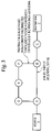
FIG. 3 is a simplified block diagram of a second hypothetical network; and
FIG. 4 is a block diagram that illustrates a computer system upon which an embodiment may be implemented.
DETAILED DESCRIPTION OF THE PREFERRED EMBODIMENT
A method and apparatus for determining network routing information based on shared risk link group information is described. In the following description, for the purposes of explanation, numerous specific details are set forth in order to provide a thorough understanding of the present invention. It will be apparent, however, to one skilled in the art that the present invention may be practiced without these specific details. In other instances, well-known structures and devices are shown in block diagram form in order to avoid unnecessarily obscuring the present invention.
Embodiments are described herein according to the following outline:
    • 1.0 General Overview
    • 2.0 Structural and Functional Overview
      • 2.1 Use of Link State Databases
      • 2.2 Determining a Shortest Path Without Information About Shared Risk Link Groups
    • 3.0 Method For Determining Routing Information Based on Shared Risk Link Group Information
    • 4.0 Implementation Mechanisms-Hardware Overview
    • 5.0 Extensions and Alternatives
      1.0 General Overview
The needs identified in the foregoing Background, and other needs and objects that will become apparent for the following description, are achieved in the present invention, which comprises, in one aspect, a method for determining network routing information based on shared risk link group information.
A method and apparatus are disclosed for performing a shortest path first network routing path determination in a data communications network based in part on information about links that are associated as shared risk link groups. Micro-loops are avoided in computing shortest path first trees by considering whether links are within shared risk link groups.
In a first approach, for each link state packet in a link state database, listed adjacencies are removed if the link between the node originating the LSP and the reported adjacency belongs to a shared risk link group for which at least one component (a local link) is known as down, and a shortest path first computation is then performed.
In a second approach, during the SPT computation and after having added a first node to a path, each neighboring node is added to a tentative tree if and only if, a link between the first node and the neighboring node does not belong to a shared risk link group for which at least one component (a local link) is known as down.
In either approach, a graph verification step may be performed using a graph representing nodes and links in the network. If the graph is disconnected, then the SPF determination is repeated without pruning any link not explicitly reported as down. Further a timer mechanism may be used to trigger re-performing an SPF computation after a time interval in which new LSPs may have been received.
In other aspects, the invention encompasses a computer apparatus and a computer-readable medium configured to carry out the foregoing steps.
The method described herein can be implemented according to any appropriate routing protocol. Generally link state protocols such as Intermediate System to Intermediate System (IS-IS) or Open Shortest Path First (OSPF) are appropriate protocols.
2.0 Structural and Functional Background
2.1 Use of Link State Databases
A data communications network comprises a plurality of interconnected sites. Traffic between sites is routed from the source to a destination via nodes of the network. Due to various factors (for instance excessive network traffic, hardware failure or software failure), nodes may enter a failure mode, during which time data routed to that node is not routed onwards by that node.
In addition to failure mode, a network change can take place when a link cost is increased or decreased, for example as a result of a network administrator intervention and in any of these cases the possibility arises that temporary de-synchronization of the network as the change is propagated through the network can give rise to loops. Other possible network changes comprise introduction of a new router (effectively corresponding to a link cost decrease from “infinity”) or removal of a router (effectively corresponding to a link cost increase to “infinity”).
FIG. 1A is an illustrative network diagram showing an example of a data communications network having as network elements nodes and links, which can be the internet or a sub-network such as a routing domain or a virtual network. The network as depicted in FIG. IA comprises nodes A, B, C, D, E, F, G, H, I, J, K, each of which is a router. Lines in FIG. 1A represent links among nodes. Assume that all the links are SRLG diverse, meaning that they do not share any SRLG, except that links 12 a, 12 b, which respectively connect nodes A-B and F-B, both belong to SRLG 1. As an example, assume that links 12 a, 12 b both traverse the same optical fiber.
Each router in the network includes software that enables a router to maintain a network map in the form of a link state database (LSDB). The LSDB is updated whenever an area of the network topology changes. If a router has interfaces on multiple areas, an LSDB is maintained for each separate area. The LSDB is calculated periodically. If no changes have occurred to the area's topology, no changes are made to the area's LSDB.
The LSDB contains entries for all the networks to which each router in an area is connected. It also assigns an outgoing cost metric to each network interface of a router. This metric measures the cost of sending traffic through an interface to the connected network. By assigning costs, router preferences can be set based on line cost, line speed or any other parameters. Assume that the link costs of all links in FIG. 1A are equal to 1, except that the cost of the A-H link 14 is 2, and the cost of the F-G link 16 is given by a variable c.
The entries in the LSDB are based on information sent in Link State Packets (LSPs), which include information generated by a router to describe the reachability of the router. Each LSP contains information identifying the interfaces on the router, the attached nodes or networks for that router and the costs to reach each of these nodes or networks. A network is considered converged when the LSDB is the same for all routers in the area.
After the LSDB has reached the converged state, each router calculates the shortest path through the network for each node or network, and each router. A Shortest Path First (SPF) Tree (SPT) is calculated and the information stored. Each router maintains its own SPT. After the SPT is built, a routing table is calculated by determining the lowest-cost route for each destination node or network. Routing tables are calculated locally at each router and the FIB updated accordingly. The network of FIG. 1A results in a LSDB as shown in Table 1 below:
TABLE 1
Router Attached Node or Network Network Usage Cost
A D 1
A H 2
B A 1
B C 1
B F 1
C B 1
C G 1
C K 1
D A 1
D E 1
E D 1
E F 1
F B 1
F E 1
F G c
G C 1
G F c
H A 2
H I 1
I H 1
I J 1
J I 1
J K 1
K C 1
K J 1

Using this LSDB, each router calculates the SPT. FIG. 1B shows a SPT for router A of FIG. 1A. This shows the shortest path from router A for each network and each router. The router A can then calculate the A routing table from this SPT.
2.2 Determining a Shortest Path Without Information About Shared Risk Link Groups
In conventional practice, SPF computations are performed without use of information about shared risk link groups. Consequently, such computations are subject to the unintended introduction of loops into the routing tables, with undesirable results, as illustrated in the following two examples.
For both examples, assume that lsp-gen(X) is the period of time a node X waits before originating a new LSP when its LSP changes, and spf-trig(X) is the period of time that a node X waits after a new LSP has been received to trigger an SPF. Both the functions lsp-gen and spf-trig may be a linear, quadratic, exponential, or other function of the number of LSP generations and SPF occurrences. Both examples address a hypothetical path followed by packets from a source S shown in FIG. 1A, which is directly attached to the node A, to a destination Z, which is directly attached to node C. P(A,Z) yields the next hop along the shortest path computed by the node A for the packet targeted to Z. For instance, at a steady state with no link failures, for the network of FIG. 1A, P(A,Z)=B. The shortest path from A to Z is A-B-C, and therefore the next hop from A to reach Z is B.
In conventional link state protocol approaches, the following process would occur in the event of a fiber cut that provokes the failure of SRLG 1. As a first case, assume that c=10, that is, the cost of the F-G link 16 is 10. At time T0, SRLG 1 fails, and thus links A-B and B-F simultaneously fail. At time T1, nodes A and F detect the link failures; typically such detection occurs almost at the same time.
In response, at time T2, nodes A and F each determine a new next hop node by computing lsp-gen(A) and lsp-gen(F), which are determined by the IGP parameters setting, and then originate a new LSP.
At time T3, nodes A and F each perform a new SPF computation, as spf-trig(A) and spf-trig(F). A and F converge, such that P(A,Z)=D. This result occurs because the shortest path from A to C is A-D-E-F-B-C, because A is unaware of the failure of the link B-F. Further, P(F,Z)=E, because the shortest path from F to C is F-E-D-A-H-I-J-K-C. At this point, a micro-loop A-D-A has been formed, because P(D,Z)=A and because the shortest path is D-A-B-C. Further, A has computed a shortest path that includes a failed link.
At time T4, node D receives the LSP of A and converges with a result of P(D,Z)=E, based on a shortest path of D-E-F-B-C, because D is not aware that the link B-F has failed. Therefore, another micro-loop A-D-E-F-E-D-A is formed.
At time T5, node E receives the LSP of F and converges with a result of P(E,Z)=D, forming a micro-loop A-D-E-D-A. At time T6, D receives the LSP of F and converges with a result of P(D,Z)=A, forming a micro-loop A-D-A. At time T7, A receives the LSP of F and converges with a result of P(A,C)=H.
In this example, several different timing sequences could occur depending on LSP propagation and queueing delays between nodes, the then-current values of lsp-gen and spf-gen, processor loads on the routers, and other factors. Further, the preceding discussion identifies only some of all potential micro-loops that may occur. The example shows, however, that undesirable loops are an inevitable result of performing SPF calculations without knowledge of concurrent failures of links that are associated in shared risk link groups.
Consider a second example, in which the link cost c of the link F-G is 5. Assume that at time T0, SRLG 1 fails, and therefore links A-B and B-F simultaneously fail. At time T1, the link failures are detected by A and F, typically at nearly the same time. At time T2, A and F determine lsp-gen(A) and lsp-gen(B), respectively, as determined by the IGP parameters, and then originate new LSPs. At time T3, after computing spf-trig(A) and spf-trig(F), A and F converge with the result that P(A,Z)=D and P(F,Z)=G, based on a shortest path of F-G-C. At this point, the micro-loop A-D-A has been formed.
At time T4, node D receives the LSP of A and converges with the result that P(D,Z)=E. At this stage, the micro-loop has disappeared.
At time T5, node E receives the LSP of F and converges with the result of P(E,Z)=F. Thus, the path is unchanged. However, the path followed by packets from A to C is non-optimal, because they follow the path A-D-E-F-G-C with a total cost of 9, even though the shortest path is A-H-I-J-K-C with a cost of 6.
At time T6, D receives the LSP of F and converges with the result that P(D,Z)=A. Consequently, a micro-loop A-D-A is formed. At time T7, A receives the LSP of F and converges with the result that P(A,C)=H.
3.0 Method of Determining Routing Information Based on Shared Risk Link Group Information
The foregoing two examples clearly highlight the need to consider SRLG information when determining a SPT in response to an SRLG failure. One approach to address this problem could be to prune all the links that belong to a common SRLG, as part of computing a SPT. However, this approach has the potential drawback of computing a non-optimal path if the failure involves a single link failure rather than the failure of a SRLG. The present approach addresses this issue by performing an additional SPF computation after a timer has elapsed, as described below.
According to an embodiment, a shortest path first process is performed that uses shared risk link group information as part of computing a shortest path first tree. Using the techniques herein, if an SRLG fails, convergence time is reduced, which is critical in networks that require fast IGP convergence and which have multiple SRLGs. Further, using the techniques herein, a more optimal route is selected.
FIG. 2A is a flow diagram of a process of performing a shortest path first determination based in part on information about shared risk link groups in a network. FIG. 2B is a flow diagram of further steps in the process of FIG. 2A. FIG. 2C is a flow diagram of steps performed upon expiration of a timer used in the process of FIG. 2A.
Referring first to FIG. 2A, the illustrated process generally is performed when an SPF determination is triggered, which typically occurs within a router in response to failure of a link local to that router, or receipt by that router of a new LSP. In block 202, the identity of the failed link is determined. For example, link identity information in the LSP may be used, or the router may locally determine the identity of a failed link. In block 204, a set of shared risk link groups S, to which the failed link belongs, is determined. The set S is determined based on the SRLG membership information that has been flooded in the IGP extensions. Hence, when a link fails, the router can determine all the links that have at least one SRLG in common with the failed link, and the set of links is represented as S in this description. For instance, suppose that link L1 is advertised with SRLG 1, 2, the link L2 belongs to SRLG 1, link L3 belongs to SRLG 3, and link L4 belongs to SRLG 1. All such links may be connected to different routers. If the link L1 fails on router R1, then R1 knows that it must exclude all the links that belong to S where S=L1, L2 and L4.
In block 206, a timer is initiated. The use of the timer for triggering other steps is described further below. A typical period for the timer is a few seconds, or the time required to receive any other potential LSPs. In an embodiment, the period of the timer is configurable.
After block 206, the process of FIG. 2A may proceed according to either of two alternatives or options, either of which is equally effective in performing a shortest path first determination based in part on information about shared risk link groups. A first alternative is represented by FIG. 2B, FIG. 2C; a second alternative is represented by FIG. 2D, FIG. 2C.
Referring first to FIG. 2B, in the first alternative, in block 208, each LSP in the link state database is scanned or reviewed. In block 210, a test is performed to determine whether the set S includes a link between a node that originated the then-current LSP and an adjacency reported in the LSP. If not, then control passes to block 214, which forms a loop with block 208 to scan each LSP in the LSDB. If the set S does include the link, then the listed adjacency is removed from the LSDB, as indicated by block 212. This step has the effect of removing, from the LSDB, each link associated in the SRLG S with a link that was reported as failed. Thereafter, as shown in block 215, an SPF computation is performed based on the modified LSDB.
An implementation can reduce processing time for performing block 208-215 by pre-computing the set S for each link, prior to any failure, and for each link the set of links that may simultaneously fail, e.g., making use of a linked list or a tree, and then perform a shortest path first tree computation.
When all LSPs in the LDSB have been processed and an SPF has been computed as shown in block 215, control passes to FIG. 2C.
Referring now to FIG. 2C, in block 216 a graph verification step is performed, to determine whether a graph that is created based on the resulting modified LDSB is a disconnected graph. A disconnected graph is a graph in which one or more child nodes no longer have a parent node. If the graph is disconnected, as tested in block 218, then in block 220 a new SPF is determined, but without pruning, as part of block 210 and block 212, any link that was not explicitly reported as failed in an LSP.
The process of FIG. 2C enables handling certain situations in which a link has failed, but an associated SRLG has not failed. An example of such a situation is now described with reference to FIG. 3, which is a simplified block diagram of a second hypothetical network. The network of FIG. 3 is similar in topology to FIG. 1A, except that the path A-H-I-J-K and the path F-G-C do not exist. Assume that link A-B fails on router B due to a local interface failure, and not due to a SRLG failure. Performing the process of FIG. 2A, FIG. 2B without also using the process of FIG. 2C would result in creating a disconnected graph based on the erroneous assumption that an SRLG failure had occurred, because link B-F would be considered unavailable as part of a SRLG with link A-B, even though an available path A-D-E-F-B-C exists between A and C. Incorporating the process of FIG. 2C avoids such a result, at the cost of slightly increased convergence time. However, the foregoing situation is expected to arise relatively infrequently, because network topology normally is designed to survive to the failure of a single SRLG. Nevertheless, the process of FIG. 2C may be considered optional and may be omitted if it is found to significantly increase the level of processing complexity during computation of an SPT.
Referring now to FIG. 2D, a second alternative process is shown. In block 240, a shortest path first tree computation is performed according to any of several known algorithms. In block 242, a test is performed to determine if a node has been added to a PATH. For convenience, in the following description such a node is referred to as node X. If so, then in block 244, a set of neighbors N for node X is determined.
In block 245, a neighbor Ni in the set of neighbors N is considered. In block 246, a test is performed to determine if the network link (X, Ni) is in the set of shared risk link groups S. If not, and only if not, then the current neighbor Ni is added to the tentative shortest first path tree TENT, as indicated by block 248. In block 250, steps 245, 246, 248 are repeated for all neighbors Ni in N. Thereafter control proceeds to FIG. 2C and the graph verification steps described above are performed.
Thus, during the SPT computation but after having added a node X to PATH, each of the neighbors Ni of X are added to TENT if and only if the link (X,Ni) does not belong to S.
At any time during either the first option or second option, the timer that was started in step 206 (FIG. 2A) may elapse. Referring again to FIG. 2A, once the timer has elapsed, as tested in block 222, a new SPF computation is triggered, as shown in block 224. Performing a new SPF computation is carried out to ensure that if a simple link failure occurs that would have been considered as an SRLG failure, the more optimal path is recomputed.
As an example, referring again to FIG. 1A, assume that link A-B fails due to a local interface failure. Without performing the process of FIG. 2C, the selected path from A to C is A-H-I-J-K-C, with a cost of 6. If the process of FIG. 2C is performed, then the selected path is A-D-E-F-B-C, with a cost of 5.
The foregoing techniques result in more rapid convergence of link state databases by routers in a network that may experience failure of links that are associated in shared risk link groups. Although the foregoing techniques require additional processing as compared to past approaches, the vast majority of network link failures have been found to have been provoked by SRLG failure. As a result, any drawbacks associated with the techniques herein are outweighed by the benefits achieved by the improvements in convergence and finding optimal paths in the case of an SRLG failure.
To avoid potential micro-loops that could result from non-coherent decisions performed by different routers, all routers in a network may execute the processes described herein. In an embodiment, the availability of these processes within a router may be announced and activated if and only if all routers in the network support the processes.
4.0 Implementation Mechanisms—Hardware Overview
FIG. 4 is a block diagram that illustrates a computer system 400 upon which the method may be implemented. The method is implemented using one or more computer programs running on a network element such as a router device. Thus, in this embodiment, the computer system 400 is a router.
Computer system 400 includes a bus 402 or other communication mechanism for communicating information, and a processor 404 coupled with bus 402 for processing information. Computer system 400 also includes a main memory 406, such as a random access memory (RAM), flash memory, or other dynamic storage device, coupled to bus 402 for storing information and instructions to be executed by processor 404. Main memory 406 also may be used for storing temporary variables or other intermediate information during execution of instructions to be executed by processor 404. Computer system 400 further includes a read only memory (ROM) 408 or other static storage device coupled to bus 402 for storing static information and instructions for processor 404. A storage device 410, such as a magnetic disk, flash memory or optical disk, is provided and coupled to bus 402 for storing information and instructions.
A communication interface 418 may be coupled to bus 402 for communicating information and command selections to processor 404. Interface 418 is a conventional serial interface such as an RS-232 or RS-422 interface. An external terminal 412 or other computer system connects to the computer system 400 and provides commands to it using the interface 418. Firmware or software running in the computer system 400 provides a terminal interface or character-based command interface so that external commands can be given to the computer system.
A switching system 416 is coupled to bus 402 and has an input interface and a respective output interface (commonly designated 419) to external network elements. The external network elements may include a plurality of additional routers 160 or a local network coupled to one or more hosts or routers, or a global network such as the Internet having one or more servers. The switching system 416 switches information traffic arriving on the input interface to output interface 419 according to pre-determined protocols and conventions that are well known. For example, switching system 416, in cooperation with processor 404, can determine a destination of a packet of data arriving on the input interface and send it to the correct destination using the output interface. The destinations may include a host, server, other end stations, or other routing and switching devices in a local network or Internet.
The computer system 400 implements as a router acting as a node the above described method generating routing information. The implementation is provided by computer system 400 in response to processor 404 executing one or more sequences of one or more instructions contained in main memory 406. Such instructions may be read into main memory 406 from another computer-readable medium, such as storage device 410. Execution of the sequences of instructions contained in main memory 406 causes processor 404 to perform the process steps described herein. One or more processors in a multi-processing arrangement may also be employed to execute the sequences of instructions contained in main memory 406. In alternative embodiments, hard-wired circuitry may be used in place of or in combination with software instructions to implement the method. Thus, embodiments are not limited to any specific combination of hardware circuitry and software.
The term “computer-readable medium” as used herein refers to any medium that participates in providing instructions to processor 404 for execution. Such a medium may take many forms, including but not limited to, non-volatile media, volatile media, and transmission media. Non-volatile media includes, for example, optical or magnetic disks, such as storage device 410. Volatile media includes dynamic memory, such as main memory 406. Transmission media includes coaxial cables, copper wire and fiber optics, including the wires that comprise bus 402. Transmission media can also take the form of wireless links such as acoustic or electromagnetic waves, such as those generated during radio wave and infrared data communications.
Common forms of computer-readable media include, for example, a floppy disk, a flexible disk, hard disk, magnetic tape, or any other magnetic medium, a CD-ROM, any other optical medium, punch cards, paper tape, any other physical medium with patterns of holes, a RAM, a PROM, and EPROM, a FLASH-EPROM, any other memory chip or cartridge, a carrier wave as described hereinafter, or any other medium from which a computer can read.
Various forms of computer readable media may be involved in carrying one or more sequences of one or more instructions to processor 404 for execution. For example, the instructions may initially be carried on a magnetic disk of a remote computer. The remote computer can load the instructions into its dynamic memory and send the instructions over a telephone line using a modem. A modem local to computer system 400 can receive the data on the telephone line and use an infrared transmitter to convert the data to an infrared signal. An infrared detector coupled to bus 402 can receive the data carried in the infrared signal and place the data on bus 402. Bus 402 carries the data to main memory 406, from which processor 404 retrieves and executes the instructions. The instructions received by main memory 406 may optionally be stored on storage device 410 either before or after execution by processor 404.
Interface 419 also provides a two-way data communication coupling to a network link that is connected to a local network. For example, the interface 419 may be an integrated services digital network (ISDN) card or a modem to provide a data communication connection to a corresponding type of telephone line. As another example, the interface 419 may be a local area network (LAN) card to provide a data communication connection to a compatible LAN. Wireless links may also be implemented. In any such implementation, the interface 419 sends and receives electrical, electromagnetic or optical signals that carry digital data streams representing various types of information.
The network link typically provides data communication through one or more networks to other data devices. For example, the network link may provide a connection through a local network to a host computer or to data equipment operated by an Internet Service Provider (ISP). The ISP in turn provides data communication services through the world wide packet data communication network now commonly referred to as the “Internet”. The local network and the Internet both use electrical, electromagnetic or optical signals that carry digital data streams. The signals through the various networks and the signals on the network link and through the interface 419, which carry the digital data to and from computer system 400, are exemplary forms of carrier waves transporting the information.
Computer system 400 can send messages and receive data, including program code, through the network(s), network link and interface 419. In the Internet example, a server might transmit a requested code for an application program through the Internet, ISP, local network and communication interface 418. One such downloaded application provides for the method as described herein.
The received code may be executed by processor 404 as it is received, and/or stored in storage device 410, or other non-volatile storage for later execution. In this manner, computer system 400 may obtain application code in the form of a carrier wave.
5.0 Extensions and Alternatives
In the foregoing specification, the invention has been described with reference to specific embodiments thereof. It will, however, be evident that various modifications and changes may be made thereto without departing from the broader spirit and scope of the invention. The specification and drawings are, accordingly, to be regarded in an illustrative rather than a restrictive sense.
Any appropriate routing protocol and mechanism can be adopted to implement the invention. The method steps set out can be carried out in any appropriate order and aspects from the examples and embodiments described juxtaposed or interchanged as appropriate. Any appropriate routing protocol can be used, such as Intermediate System—Intermediate System (IS-IS) or Open Shortest Path First (OSPF). Similarly any appropriate network can provide the platform for implementation of the method.

Claims (20)

1. A method of determining network routing information based on shared risk link group information in a data communications network comprising nodes and links, the method comprising the computer-implemented steps of:
receiving information identifying a failed link in the network;
receiving information defining one or more shared risk link groups to which the failed link belongs,
each of the one or more shared risk link groups logically comprising two or more links, one of the two or more links being the failed link, and each link in a shared risk link group sharing a physical resource whose failure risks affecting all of the links in the shared risk link group;
accessing a link state database that stores information defining one or more links and adjacent nodes;
determining whether each link defined in the link state database is in the one or more shared risk link groups; and
removing an adjacent node from the link state database for a link other than the failed link that is determined to be in one of the shared risk link groups.
2. A method as recited in claim 1, performed as part of determining a shortest path through the network from a source to a destination.
3. A method as recited in claim 1, further comprising the steps of:
determining whether a graph of the data communications network based on the link state database is disconnected; and
if the graph is disconnected, then determining a new shortest path through the network to a destination network element without removing any link that has not been explicitly reported by another network element as failed.
4. A method according to any of claim 1, 2, or 3, further comprising the steps of:
initiating a timer prior to the accessing step;
when the timer expires, determining a new shortest path through the network to a destination network element.
5. A method of determining network routing information based on shared risk link group information in a data communications network comprising nodes and links, the method comprising the steps of:
receiving information identifying a failed link in the network;
receiving information defining one or more shared risk link groups to which the failed link belongs,
each of the one or more shared risk link groups logically comprising two or more links, one of the two or more links being the failed link, and each link in a shared risk link group sharing a physical resource whose failure risks affecting all of the links in the shared risk link group;
determining the set of links S logically comprising all links belonging to the one or more shared risk links groups to which the failed link belongs;
during computation of a shortest path first tree, after having added a node X to a path, adding each neighbor Ni of node X to a tentative tree if and only if a link (X, Ni) does not belong to S.
6. A method of determining network routing information based on shared risk link group information in a data communications network comprising nodes and links, the method comprising the steps of:
receiving information identifying a failed link in the network;
receiving information defining one or more shared risk link groups to which the failed link belongs,
each of the one or more shared risk link groups logically comprising two or more links, one of the two or more links being the failed link, and each link in a shared risk link group sharing a physical resource whose failure risks affecting all of the links in the shared risk link group;
initiating computation of a shortest path first tree;
adding a first node to a path as part of the computation;
determining a set of neighbors of the first node; and
adding each neighbor node to a tentative tree if and only if a link between the first node and the neighbor node does not belong to one of the shared risk link groups.
7. A method as recited in claim 6, further comprising the steps of:
determining whether a graph representing the data communications network is disconnected; and
if the graph is disconnected, then determining a new shortest path through the network to a destination network element without removing any link that has not been explicitly reported by another network element as failed.
8. A method according to any of claim 6 or 7, further comprising the steps of:
initiating a timer prior to the accessing step;
when the timer expires, determining a new shortest path through the network to a destination network element.
9. A computer readable storage medium storing one or more sequences of computer executable instructions for determining network routing information based on shared risk link group information in a data communications network comprising nodes and links in a data communications network having as elements links and nodes, which instructions, when executed by one or more processors, cause the one or more processors to perform
receiving information identifying a failed link in the network;
receiving information defining one or more shared risk link groups to which the failed link belongs,
each of the one or more shared risk link groups logically comprising two or more links, one of the two or more links being the failed link, and each link in a shared risk link group sharing a physical resource whose failure risks affecting all of the links in the shared risk link group;
accessing a link state database that stores information defining one or more links and adjacent nodes;
determining whether each link defined in the link state database is in the one or more shared risk link groups; and
removing an adjacent node from the link state database for a link other than the failed link that is determined to be in one of the shared risk link groups.
10. A computer readable storage medium storing one or more sequences of computer executable instructions for determining network routing information based on shared risk link group information in a data communications network comprising nodes and links in a data communications network having as elements links and nodes, which instructions, when executed by one or more processors, cause the one or more processors to perform
receiving information identifying a failed link in the network;
receiving information defining one or more shared risk link groups to which the failed link belongs,
each of the one or more shared risk link groups logically comprising two or more links, one of the two or more links being the failed link, and each link in a shared risk link group sharing a physical resource whose failure risks affecting all of the links in the shared risk link group;
determining the set of links S logically comprising all links belonging to the one or more shared risk links groups to which the failed link belongs;
during computation of a shortest path first tree, after having added a node X to a path, adding each neighbor Ni of node X to a tentative tree if and only if a link (X, Ni) does not belong to S.
11. An apparatus for generating routing information based on shared risk link group information in a data communications network having as elements nodes and links, comprising:
means for receiving information identifying a failed link in the network;
means for receiving information defining one or more shared risk link groups to which the failed link belongs,
each of the one or more shared risk link groups logically comprising two or more links, one of the two or more links being the failed link, and each link in a shared risk link group sharing a physical resource whose failure risks affecting all of the links in the shared risk link group;
means for accessing a link state database that stores information defining one or more links and adjacent nodes;
means for determining whether each link defined in the link state database is in the one or more shared risk link groups; and
means for removing an adjacent node from the link state database for a link other than the failed link that is determined to be in one of the shared risk link groups.
12. An apparatus as recited in claim 11, implemented as part of a means for determining a shortest path through the network from a source to a destination.
13. An apparatus as recited in claim 11, further comprising:
means for determining whether a graph of the data communications network based on the link state database is disconnected; and
means for determining, if the graph is disconnected, a new shortest path through the network to a destination network element without removing any link that has not been explicitly reported by another network element as failed.
14. An apparatus according to any of claims 11, 12, or 13, further comprising:
means for initiating a timer prior to the accessing step;
means for determining, when the timer expires, a new shortest path through the network to a destination network element.
15. An apparatus for determining network routing information based on shared risk link group information in a data communications network comprising nodes and links, the apparatus comprising:
means for receiving information identifying a failed link in the network;
means for receiving information defining one or more shared risk link groups to which the failed link belongs,
each of the one or more shared risk link groups logically comprising two or more links, one of the two or more links being the failed link, and each link in a shared risk link group sharing a physical resource whose failure risks affecting all of the links in the shared risk link group;
determining the set of links S logically comprising all links belonging to the one or more shared risk links groups to which the failed link belongs;
means for adding, during computation of a shortest path first tree, after having added a node X to a path, each neighbor Ni of node X to a tentative tree if and only if a link (X, Ni) does not belong to S.
16. An apparatus for determining network routing information based on shared risk link group information in a data communications network comprising nodes and links, the apparatus comprising:
means for receiving information identifying a failed link in the network;
means for receiving information defining one or more shared risk link groups to which the failed link belongs,
each of the one or more shared risk link groups logically comprising two or more links, one of the two or more links being the failed link, and each link in a shared risk link group sharing a physical resource whose failure risks affecting all of the links in the shared risk link group;
means for initiating computation of a shortest path first tree;
means for adding a first node to a path as part of the computation;
means for determining a set of neighbors of the first node; and
means for adding each neighbor node to a tentative tree if and only if a link between the first node and the neighbor node does not belong to one of the shared risk link groups.
17. An apparatus as recited in claim 16, further comprising:
means for determining whether a graph representing the data communications network is disconnected; and
means for determining, if the graph is disconnected, a new shortest path through the network to a destination network element without removing any link that has not been explicitly reported by another network element as failed.
18. An apparatus according to any of claims 16 or 17, further comprising:
means for initiating a timer prior to the accessing step;
means for determining, when the timer expires, a new shortest path through the network to a destination network element.
19. An apparatus for generating routing information in a data communications network having as elements links and nodes, the apparatus comprising:
one or more processors;
a network interface communicatively coupled to the processor and configured to communicate one or more packet flows among the processor and a network; and
a computer readable medium storing one or more sequences of instructions for generating routing information which instructions, when executed by one more processors, cause the one or more processors to perform:
receiving information identifying a failed link in the network;
receiving information defining one or more shared risk link groups to which the failed link belongs,
each of the one or more shared risk link groups logically comprising two or more links, one of the two or more links being the failed link, and each link in a shared risk link group sharing a physical resource whose failure risks affecting all of the links in the shared risk link group;
accessing a link state database that stores information defining one or more links and adjacent nodes;
determining whether each link defined in the link state database is in the one or more shared risk link groups; and
removing an adjacent node from the link state database for a link other than the failed link that is determined to be in one of the shared risk link groups.
20. An apparatus for generating routing information in a data communications network having as elements links and nodes, the apparatus comprising:
one or more processors;
a network interface communicatively coupled to the processor and configured to communicate one or more packet flows among the processor and a network; and
a computer readable medium storing one or more sequences of instructions for generating routing information which instructions, when executed by one more processors, cause the one or more processors to perform
receiving information identifying a failed link in the network;
receiving information defining one or more shared risk link groups to which the failed link belongs,
each of the one or more shared risk link groups logically comprising two or more links, one of the two or more links being the failed link, and each link in a shared risk link group sharing a physical resource whose failure risks affecting all of the links in the shared risk link group;
determining the set of links S logically comprising all links belonging to the one or more shared risk links groups to which the failed link belongs;
during computation of a shortest path first tree, after having added a node X to a path, adding each neighbor Ni of node X to a tentative tree if and only if a link (X, Ni) does not belong to S.
US10/719,003 2003-11-21 2003-11-21 Method and apparatus for determining network routing information based on shared risk link group information Expired - Fee Related US7428213B2 (en)

Priority Applications (4)

Application Number Priority Date Filing Date Title
US10/719,003 US7428213B2 (en) 2003-11-21 2003-11-21 Method and apparatus for determining network routing information based on shared risk link group information
CN200480033399.8A CN100542111C (en) 2003-11-21 2004-11-09 Determine the method and apparatus of network routing information based on shared risk link group information
EP04800942.7A EP1685681B1 (en) 2003-11-21 2004-11-09 Method and apparatus for determining network routing information based on shared risk link group information
PCT/US2004/037420 WO2005053234A1 (en) 2003-11-21 2004-11-09 Method and apparatus for determining network routing information based on shared risk link group information

Applications Claiming Priority (1)

Application Number Priority Date Filing Date Title
US10/719,003 US7428213B2 (en) 2003-11-21 2003-11-21 Method and apparatus for determining network routing information based on shared risk link group information

Publications (2)

Publication Number Publication Date
US20050111349A1 US20050111349A1 (en) 2005-05-26
US7428213B2 true US7428213B2 (en) 2008-09-23

Family

ID=34591215

Family Applications (1)

Application Number Title Priority Date Filing Date
US10/719,003 Expired - Fee Related US7428213B2 (en) 2003-11-21 2003-11-21 Method and apparatus for determining network routing information based on shared risk link group information

Country Status (4)

Country Link
US (1) US7428213B2 (en)
EP (1) EP1685681B1 (en)
CN (1) CN100542111C (en)
WO (1) WO2005053234A1 (en)

Cited By (11)

* Cited by examiner, † Cited by third party
Publication number Priority date Publication date Assignee Title
US20070086363A1 (en) * 2005-10-14 2007-04-19 Wakumoto Shaun K Switch meshing using multiple directional spanning trees
US20080317055A1 (en) * 2003-02-03 2008-12-25 Jerker Mattias Zetterlund Shared risk group handling within a media gateway
US20100309919A1 (en) * 2009-06-04 2010-12-09 Clarence Filsfils Label distribution protocol label filtering
US20110044351A1 (en) * 2009-08-19 2011-02-24 Brocade Communications Systems, Inc. Techniques for efficiently updating routing information upon shortest path tree computation
US20110051594A1 (en) * 2009-08-26 2011-03-03 Noblis, Inc. System and Method for Providing Network Resiliency
US20110069706A1 (en) * 2009-09-21 2011-03-24 Brocade Communications Systems, Inc. Techniques for next-hop optimization
US20120307644A1 (en) * 2011-06-02 2012-12-06 Cisco Technology, Inc. System and method for link protection using shared srlg association
US8503464B2 (en) 2011-05-20 2013-08-06 Brocade Communications Systems, Inc. Techniques for efficiently updating routing information
US8542578B1 (en) 2010-08-04 2013-09-24 Cisco Technology, Inc. System and method for providing a link-state path to a node in a network environment
US8743679B2 (en) 2011-02-28 2014-06-03 Cisco Technology, Inc. Client diversity policy sharing with the transport layer
US9054957B2 (en) 2003-02-03 2015-06-09 Telefonaktiebolaget L M Ericsson (Publ) Shared risk group handling within a media gateway

Families Citing this family (27)

* Cited by examiner, † Cited by third party
Publication number Priority date Publication date Assignee Title
US7701848B2 (en) * 2003-07-11 2010-04-20 Chunming Qiao Efficient trap avoidance and shared protection method in survivable networks with shared risk link groups and a survivable network
US7715403B2 (en) * 2003-10-01 2010-05-11 Genband Inc. Methods, systems, and computer program products for load balanced and symmetric path computations for VoIP traffic engineering
US7463654B2 (en) * 2003-12-22 2008-12-09 3Com Corporation Stackable routers employing a routing protocol
US7561534B2 (en) * 2004-06-30 2009-07-14 Alcatel-Lucent Usa Inc. Methods of network routing having improved resistance to faults affecting groups of links subject to common risks
KR101255857B1 (en) * 2006-03-16 2013-04-17 리서치 파운데이션 오브 더 시티 유니버시티 오브 뉴욕 Tree-guided distributed link state routing method
US8089904B2 (en) * 2006-08-01 2012-01-03 Opnet Technologies, Inc. Link inference in large networks based on incomplete data
US7831700B2 (en) * 2006-10-16 2010-11-09 Futurewei Technologies, Inc. Distributed PCE-based system and architecture in multi-layer network
US8009669B2 (en) * 2006-10-16 2011-08-30 Futurewei Technologies, Inc. System of path computation element protocol support for large-scale concurrent path computation
US7940776B2 (en) 2007-06-13 2011-05-10 Cisco Technology, Inc. Fast re-routing in distance vector routing protocol networks
US8423668B2 (en) * 2007-12-31 2013-04-16 Cisco Technology, Inc. Link state protocol routing message containment
US7852751B2 (en) * 2008-02-15 2010-12-14 Cisco Technology, Inc. Constructing repair paths around multiple non-available links in a data communications network
WO2009130941A1 (en) * 2008-04-22 2009-10-29 日本電気株式会社 Relay device, network system, channel switching method, and recording medium
US9210067B1 (en) * 2008-07-11 2015-12-08 Google Inc. Method and apparatus for exchanging routing information
CN101588621B (en) * 2009-06-30 2010-10-27 北京科技大学 Random routing method based on risk assessment in multi-hop cognition wireless network
CN102026044B (en) * 2009-09-14 2014-02-05 中兴通讯股份有限公司 Processing method for routing and apparatus thereof
US9124524B2 (en) * 2011-06-29 2015-09-01 Broadcom Corporation System and method for priority based flow control between nodes
US9590856B1 (en) * 2011-07-08 2017-03-07 The Boeing Company Multicast stream mapping
US20140003224A1 (en) * 2012-06-27 2014-01-02 Google Inc. Deterministic network failure detection
US9219682B2 (en) * 2012-11-05 2015-12-22 Cisco Technology, Inc. Mintree-based routing in highly constrained networks
US9705786B2 (en) * 2013-02-12 2017-07-11 Infinera Corporation Demand advertisement method for shared mesh protection path computation
CN104168192A (en) * 2014-08-08 2014-11-26 北京邮电大学 Rerouting method and device in fault network
WO2016039758A1 (en) 2014-09-11 2016-03-17 Hewlett Packard Enterprise Development Lp Non-minimum cost forwarding for packet-switched networks
WO2019079961A1 (en) * 2017-10-24 2019-05-02 华为技术有限公司 Method and device for determining shared risk link group
CN109873762B (en) * 2017-12-05 2021-08-31 中国电信股份有限公司 Path scheduling method, path scheduling device and computer-readable storage medium
CN111654437B (en) * 2020-06-10 2022-09-20 锐捷网络股份有限公司 Message forwarding method and device based on data center
CN114553767A (en) * 2021-11-04 2022-05-27 国网浙江省电力有限公司湖州供电公司 Rerouting technology for survivability of power communication network
US11736385B1 (en) * 2022-08-17 2023-08-22 Juniper Networks, Inc. Distributed flooding technique

Citations (29)

* Cited by examiner, † Cited by third party
Publication number Priority date Publication date Assignee Title
US4827411A (en) * 1987-06-15 1989-05-02 International Business Machines Corporation Method of maintaining a topology database
US5243592A (en) 1990-10-15 1993-09-07 Digital Equipment Corporation Method and apparatus for distance vector routing on datagram point-to-point links
US5253248A (en) 1990-07-03 1993-10-12 At&T Bell Laboratories Congestion control for connectionless traffic in data networks via alternate routing
US5999286A (en) 1997-01-09 1999-12-07 Alcatel Method and system for restoring a distributed telecommunications network
US6032194A (en) 1997-12-24 2000-02-29 Cisco Technology, Inc. Method and apparatus for rapidly reconfiguring computer networks
US6128750A (en) 1996-11-14 2000-10-03 Emc Corporation Fail-over switching system
US6256295B1 (en) 1997-09-25 2001-07-03 Nortel Networks Limited Method and apparatus for determining multiple minimally-overlapping paths between nodes in a network
US6278687B1 (en) 1997-07-31 2001-08-21 Marconi Communications Limited MA alternate routeing
US20020012318A1 (en) * 2000-06-07 2002-01-31 Ryuichi Moriya Network managing method, network node apparatus, and mesh-type network
US6377542B1 (en) 1997-07-31 2002-04-23 Marconi Communications Limited Rap alternate routeing for ISO 10589
US20020093954A1 (en) 2000-07-05 2002-07-18 Jon Weil Failure protection in a communications network
US20020112072A1 (en) * 2001-02-12 2002-08-15 Maple Optical Systems, Inc. System and method for fast-rerouting of data in a data communication network
US6535481B1 (en) 1999-08-20 2003-03-18 Nortel Networks Limited Network data routing protection cycles for automatic protection switching
US6578084B1 (en) 1999-10-15 2003-06-10 Cisco Technology, Inc. Packet processing using encapsulation and decapsulation chains
US6578086B1 (en) * 1999-09-27 2003-06-10 Nortel Networks Limited Dynamically managing the topology of a data network
US6590868B2 (en) 2001-06-02 2003-07-08 Redback Networks Inc. Method and apparatus for restart communication between network elements
US20030147352A1 (en) * 2002-02-06 2003-08-07 Nec Corporation Path establishment method for establishing paths of different fault recovery types in a communications network
US6636498B1 (en) 1999-01-08 2003-10-21 Cisco Technology, Inc. Mobile IP mobile router
US6668282B1 (en) 2000-08-02 2003-12-23 International Business Machines Corporation System and method to monitor and determine if an active IPSec tunnel has become disabled
US6697325B1 (en) * 1999-12-07 2004-02-24 Nortel Networks Limited System, device, and method for expediting reconvergence in a communication network
US6711125B1 (en) 1999-08-02 2004-03-23 Extreme Networks Provisioning networks for reliable quality of service
US20040085894A1 (en) * 2002-10-31 2004-05-06 Linghsiao Wang Apparatus for link failure detection on high availability Ethernet backplane
US20050031339A1 (en) * 2003-07-11 2005-02-10 Chumning Qiao Efficient trap avoidance and shared protection method in survivable networks with shared risk link groups and a survivable network
US6882627B2 (en) * 2001-06-14 2005-04-19 Tropic Networks Methods and apparatus for selecting multiple paths taking into account shared risk
US6944131B2 (en) * 1999-09-27 2005-09-13 Nortel Networks Limited State information and routing table updates in large scale data networks
US6982951B2 (en) * 2000-12-21 2006-01-03 At&T Corp. Method for selecting a restoration path in a mesh network
US7099286B1 (en) * 2002-05-22 2006-08-29 Cisco Technology, Inc. Method and system for finding shared risk diverse paths
US7113481B2 (en) * 2001-10-10 2006-09-26 Alcatel Informed dynamic path protection for optical networks
US20070011284A1 (en) * 2002-02-21 2007-01-11 France Telecom Sa Dynamic distributed method for local protection of a label switching path

Family Cites Families (1)

* Cited by examiner, † Cited by third party
Publication number Priority date Publication date Assignee Title
US7035209B2 (en) * 2001-08-23 2006-04-25 Tropic Networks Inc. Control communications in communications networks

Patent Citations (30)

* Cited by examiner, † Cited by third party
Publication number Priority date Publication date Assignee Title
US4827411A (en) * 1987-06-15 1989-05-02 International Business Machines Corporation Method of maintaining a topology database
US5253248A (en) 1990-07-03 1993-10-12 At&T Bell Laboratories Congestion control for connectionless traffic in data networks via alternate routing
US5243592A (en) 1990-10-15 1993-09-07 Digital Equipment Corporation Method and apparatus for distance vector routing on datagram point-to-point links
US6128750A (en) 1996-11-14 2000-10-03 Emc Corporation Fail-over switching system
US5999286A (en) 1997-01-09 1999-12-07 Alcatel Method and system for restoring a distributed telecommunications network
US6278687B1 (en) 1997-07-31 2001-08-21 Marconi Communications Limited MA alternate routeing
US6377542B1 (en) 1997-07-31 2002-04-23 Marconi Communications Limited Rap alternate routeing for ISO 10589
US6256295B1 (en) 1997-09-25 2001-07-03 Nortel Networks Limited Method and apparatus for determining multiple minimally-overlapping paths between nodes in a network
US6032194A (en) 1997-12-24 2000-02-29 Cisco Technology, Inc. Method and apparatus for rapidly reconfiguring computer networks
US6636498B1 (en) 1999-01-08 2003-10-21 Cisco Technology, Inc. Mobile IP mobile router
US6711125B1 (en) 1999-08-02 2004-03-23 Extreme Networks Provisioning networks for reliable quality of service
US6535481B1 (en) 1999-08-20 2003-03-18 Nortel Networks Limited Network data routing protection cycles for automatic protection switching
US6944131B2 (en) * 1999-09-27 2005-09-13 Nortel Networks Limited State information and routing table updates in large scale data networks
US6578086B1 (en) * 1999-09-27 2003-06-10 Nortel Networks Limited Dynamically managing the topology of a data network
US6578084B1 (en) 1999-10-15 2003-06-10 Cisco Technology, Inc. Packet processing using encapsulation and decapsulation chains
US6697325B1 (en) * 1999-12-07 2004-02-24 Nortel Networks Limited System, device, and method for expediting reconvergence in a communication network
US20020012318A1 (en) * 2000-06-07 2002-01-31 Ryuichi Moriya Network managing method, network node apparatus, and mesh-type network
US20020093954A1 (en) 2000-07-05 2002-07-18 Jon Weil Failure protection in a communications network
US6668282B1 (en) 2000-08-02 2003-12-23 International Business Machines Corporation System and method to monitor and determine if an active IPSec tunnel has become disabled
US6982951B2 (en) * 2000-12-21 2006-01-03 At&T Corp. Method for selecting a restoration path in a mesh network
US20020112072A1 (en) * 2001-02-12 2002-08-15 Maple Optical Systems, Inc. System and method for fast-rerouting of data in a data communication network
US20020116669A1 (en) * 2001-02-12 2002-08-22 Maple Optical Systems, Inc. System and method for fault notification in a data communication network
US6590868B2 (en) 2001-06-02 2003-07-08 Redback Networks Inc. Method and apparatus for restart communication between network elements
US6882627B2 (en) * 2001-06-14 2005-04-19 Tropic Networks Methods and apparatus for selecting multiple paths taking into account shared risk
US7113481B2 (en) * 2001-10-10 2006-09-26 Alcatel Informed dynamic path protection for optical networks
US20030147352A1 (en) * 2002-02-06 2003-08-07 Nec Corporation Path establishment method for establishing paths of different fault recovery types in a communications network
US20070011284A1 (en) * 2002-02-21 2007-01-11 France Telecom Sa Dynamic distributed method for local protection of a label switching path
US7099286B1 (en) * 2002-05-22 2006-08-29 Cisco Technology, Inc. Method and system for finding shared risk diverse paths
US20040085894A1 (en) * 2002-10-31 2004-05-06 Linghsiao Wang Apparatus for link failure detection on high availability Ethernet backplane
US20050031339A1 (en) * 2003-07-11 2005-02-10 Chumning Qiao Efficient trap avoidance and shared protection method in survivable networks with shared risk link groups and a survivable network

Non-Patent Citations (35)

* Cited by examiner, † Cited by third party
Title
Amir Hermelin, et al., "Extending the Number of IS-IS LSP Fragments Beyond the 256 Limit, draft-ietf-isis-lsp-frags-02.txt," Network Working Group, Internet Draft, http://www.ietf.org/internet-drafts/draft-ietf-isis-ext-lsp-frags-02.txt, data retrieved Apr. 28, 2004, pp. 1-12.
C. Perkins, "IP Mobility Support for IPv4," Jan. 2002, IETF Network Working Group Request for Comments 3220 (RFC 322), from www.ietf.org, pp. 1-98.
Cisco Systems, Inc., "AppleTalk, IP, and Novell IPX Overview," Sep. 9, 2002, pp. IV-1-IV-6.
Cisco Systems, Inc., "Configuring Mobile IP," http://www.cisco.com/warp/public/732/Tech/mobile/IP/techdocument, 2003, 38 pages.
Cisco Systems, Inc., "Trace," Chapter 32, Sep. 13, 2002, pp. 32-1-32-12.
Cisco Systems, Inc., "Tunnel ToS," Cisco IOS Release 12.0(17)S, 12.0(17)ST, 12.2(8)T, and 12.2(14)S, Jan. 28, 2003, pp. 1-15.
Cisco Systems, Inc., "White Paper, Cisco Mobile IP, Executive Summary," 2002, http://www.cisco.com/warp/public/cc/pd/10sw/prodlit/mbxul<SUB>-</SUB>wp.htm, 8 pages.
Cisco Systems, Inc., "Why Are OSPF Neighbors Stuck in Exstart/Exchange State?," 1992-2003, 8 pages.
Current claims in China patent application 200480033399.8 (3 pgs) with marked up copy (4 pgs).
Current Claims, PCT/US04/33827, 6 pages.
D. Johnson, et al., "Mobility Support in Ipv6, draft-ietf-mobileip-ipv6-21.txt," Feb. 26, 2003, http://www.ietf.org/html.charters/mobileip-charter.html, pp. 1-169.
Fei Dai et al., "On Independently Finding Converging Paths in Internet," 2001, pp. 1-13.
Fortz, Bernard, et al., "Optimizing OSPF/IS-IS Weights in a Changing World," IEEE JSAC Special Issue on Advances in Fundamentals of Network Management, Spring 2002, pp. 1-31.
International Searching Authority, International Search Report, PCT/US04/33827, dated Mar. 28, 2005, 8 pages.
Jie Wu et al., "An Extended Fault-Tolerant Link-State Routing Protocol in the Internet," 2001, 7 pages.
M. Leelanivas, et al., "Graceful Restart Mechanism for Label Distribution Protocol," Feb. 2003, Network Working Group, Request for Comments: 3478, http://rfc3478.x42.com, data retrieved Apr. 28, 2004, pp. 1-11.
M. Shand, et al., "Restart signaling for IS-IS, draft-ietf-isis-restart-04.txt," Jul. 2003, Network Working Group, Internet Draft, http://vesuvio.ipv6.tilab.com/internet-drafts/draft-ietf-isis-restart-04.txt, data retrieved Apr. 28, 2004, pp. 1-18.
M. Shand, et al., Restart signaling for IS-IS, draft-ietf-isis-restart-05.txt, Jan. 2004, Network Working Group, Internet Draft, http://www.ietf.org/internet-drafts/draft-ietf-isis-restart-05.txt, data retrieved Apr. 28, 2004, pp. 1-20.
M. Watari, "Masafumi Watari's Web Site," "Papers" page, printed May 7, 2003, http://www.sfc.wide.ad.jp/~watari/papers.html, 1 page.
Mikkel Thorup, "Fortifying OSPF/IS-IS against link-failure," Sep. 7, 2001, pp. 1-10.
Office Action from China for foreign patent application 200480033399.8 dated Feb. 29, 2008 (4 pgs) with English Translation (4 pgs).
Paolo Narváez et al., "Fault-Tolerant Routing in the Internet without Flooding," 1998, pp. 1-13.
Paolo Narváez et al., "Local Restoration Algorithm for Link-State Routing Protocols," 1998, 6 pages.
R. Balay, et al., "IS-IS Mesh Groups," Oct. 2000, Network Working Group, Request for Comments: 2973, pp. 1-8.
Ryuji Wakikawa, et al., "Mobility Related Research at InternetCAR Project," http://www.connectathon.org/talks03/cthon-keio.pdf, Mar. 5, 2003, 12 pages.
S. Deering, et al., "Internet Protocol, Version 6 (IPv6), Specification," Dec. 1998, IETF Network Working Group Request for Comments 2460, from www.ietf.org, pp. 1-39.
Takuya Yoshihiro, "Design and Analysis of Routing Algorithms toward the Next Generation Internet," Dec. 2002, 98 pages.
Thorup, Mikkel, "OSPF Areas Considered Harmful," AT&T Labs-Research, Florham Park, NJ, Apr. 22, 2003, pp. 1-9.
Thorup, Mikkel, et al., "Avoiding Ties in Shortest Path First Routing," AT&T Labs-Research, Shannon Laboratory, Florham Park, NJ, pp. 1-13.
U.S. Appl. No. 10/323,358, filed Dec. 17, 2002, Ian Michael Charles Shand, entitled "Method and Apparatus for Advertising a Link Cost in a Data Communications Network," 29 pages.
U.S. Appl. No. 10/340,371, filed Jan. 9, 2003, Kevin George Miles, et al., entitled Method and Apparatus for Constructing a Backup Route in a Data Communications Network, 33 pages.
U.S. Appl. No. 10/442,589, filed May 20, 2003, Stewart Frederick Bryant, et al., entitled "A Method and Apparatus for Constructing a Transition Route in a Data Communication Network," 45 pages.
University of Southern California, Information Sciences Institute, "Internet Protocol, DARPA Internet Program, Protocol Specification," Sep. 1981 (IETF RFC 791), 48 pages.
Wang, Zheng et al., "Shortest Path First with Emergency Exits," ACM 089791-405-8/90/0009/0166, 1990, pp. 166-176.
William Stallings, "Mobile IP," http://www.cisco.com/warp/public/ipi<SUB>-</SUB>4-2<SUB>-</SUB>ip.html, 11 pages.

Cited By (22)

* Cited by examiner, † Cited by third party
Publication number Priority date Publication date Assignee Title
US20080317055A1 (en) * 2003-02-03 2008-12-25 Jerker Mattias Zetterlund Shared risk group handling within a media gateway
US7876674B2 (en) * 2003-02-03 2011-01-25 Telefonaktiebolaget L M Ericsson (Publ) Shared risk group handling within a media gateway
US9054957B2 (en) 2003-02-03 2015-06-09 Telefonaktiebolaget L M Ericsson (Publ) Shared risk group handling within a media gateway
US20070086363A1 (en) * 2005-10-14 2007-04-19 Wakumoto Shaun K Switch meshing using multiple directional spanning trees
US7623533B2 (en) * 2005-10-14 2009-11-24 Hewlett-Packard Development Company, L.P. Switch meshing using multiple directional spanning trees
US20100309919A1 (en) * 2009-06-04 2010-12-09 Clarence Filsfils Label distribution protocol label filtering
US8644315B2 (en) 2009-06-04 2014-02-04 Cisco Technology, Inc. Label distribution protocol label filtering
US20110044351A1 (en) * 2009-08-19 2011-02-24 Brocade Communications Systems, Inc. Techniques for efficiently updating routing information upon shortest path tree computation
US8565247B2 (en) 2009-08-19 2013-10-22 Brocade Communications Systems, Inc. Techniques for efficiently updating routing information upon shortest path tree computation
US9106512B2 (en) 2009-08-19 2015-08-11 Brocade Communications Systems, Inc. Techniques for efficiently updating routing information upon shortest path tree computation
US7986617B2 (en) 2009-08-26 2011-07-26 Noblis, Inc. System and method for providing network resiliency
US20110228702A1 (en) * 2009-08-26 2011-09-22 Noblis, Inc. System and Method for Providing Network Resiliency
US8472347B2 (en) 2009-08-26 2013-06-25 Noblis, Inc. System and method for providing network resiliency
US20110051594A1 (en) * 2009-08-26 2011-03-03 Noblis, Inc. System and Method for Providing Network Resiliency
US20110069706A1 (en) * 2009-09-21 2011-03-24 Brocade Communications Systems, Inc. Techniques for next-hop optimization
US8873563B2 (en) 2009-09-21 2014-10-28 Brocade Communications Systems, Inc. Techniques for next-hop optimization
US8542578B1 (en) 2010-08-04 2013-09-24 Cisco Technology, Inc. System and method for providing a link-state path to a node in a network environment
US8743679B2 (en) 2011-02-28 2014-06-03 Cisco Technology, Inc. Client diversity policy sharing with the transport layer
US8503464B2 (en) 2011-05-20 2013-08-06 Brocade Communications Systems, Inc. Techniques for efficiently updating routing information
US9007918B2 (en) 2011-05-20 2015-04-14 Brocade Communications Systems, Inc. Techniques for efficiently updating routing information
US20120307644A1 (en) * 2011-06-02 2012-12-06 Cisco Technology, Inc. System and method for link protection using shared srlg association
US8576708B2 (en) * 2011-06-02 2013-11-05 Cisco Technology, Inc. System and method for link protection using shared SRLG association

Also Published As

Publication number Publication date
CN1879356A (en) 2006-12-13
EP1685681B1 (en) 2013-05-15
WO2005053234A1 (en) 2005-06-09
US20050111349A1 (en) 2005-05-26
EP1685681A4 (en) 2009-01-21
EP1685681A1 (en) 2006-08-02
CN100542111C (en) 2009-09-16

Similar Documents

Publication Publication Date Title
US7428213B2 (en) Method and apparatus for determining network routing information based on shared risk link group information
EP3732894B1 (en) Interior gateway protocol flood minimization
CN107409093B (en) Automatic optimal route reflector root address assignment and fast failover for route reflector clients in a network environment
US7466661B1 (en) Method and apparatus for establishing adjacency for a restarting router during convergence
US7580360B2 (en) Method and apparatus for generating routing information in a data communications network
US7707307B2 (en) Method and apparatus for constructing a backup route in a data communications network
US7554921B2 (en) Method and apparatus for generating routing information in a data communication network
US7792991B2 (en) Method and apparatus for advertising a link cost in a data communications network
US7099286B1 (en) Method and system for finding shared risk diverse paths
US20210203562A1 (en) System and method to recover from link or node failure in a network
US8908676B2 (en) Automatically detecting best paths from shadow route reflectors
US7920566B2 (en) Forwarding data in a data communication network
RU2521092C2 (en) Ldp and igp synchronisation for broadcast networks
EP1905196B1 (en) Method and apparatus for updating label-switched paths
US8018953B1 (en) Adaptive, deterministic ant routing approach for updating network routing information
US20060239211A1 (en) Method and apparatus for constructing a forwarding information structure
CA2537898C (en) Method and apparatus for generating routing information in a data communications network
US11757762B2 (en) Service operation method and device, and storage medium and electronic device

Legal Events

Date Code Title Description
AS Assignment

Owner name: CISCO TECHNOLOGY, INC., CALIFORNIA

Free format text: ASSIGNMENT OF ASSIGNORS INTEREST;ASSIGNORS:VASSEUR, JEAN PHILIPPE;PREVIDI, STEFANO B.;FILSFILS, CLARENCE;AND OTHERS;REEL/FRAME:015894/0156;SIGNING DATES FROM 20040113 TO 20040927

STCF Information on status: patent grant

Free format text: PATENTED CASE

FPAY Fee payment

Year of fee payment: 4

FPAY Fee payment

Year of fee payment: 8

FEPP Fee payment procedure

Free format text: MAINTENANCE FEE REMINDER MAILED (ORIGINAL EVENT CODE: REM.); ENTITY STATUS OF PATENT OWNER: LARGE ENTITY

LAPS Lapse for failure to pay maintenance fees

Free format text: PATENT EXPIRED FOR FAILURE TO PAY MAINTENANCE FEES (ORIGINAL EVENT CODE: EXP.); ENTITY STATUS OF PATENT OWNER: LARGE ENTITY

STCH Information on status: patent discontinuation

Free format text: PATENT EXPIRED DUE TO NONPAYMENT OF MAINTENANCE FEES UNDER 37 CFR 1.362

FP Lapsed due to failure to pay maintenance fee

Effective date: 20200923