US7421303B2 - Parallel LCP solver and system incorporating same - Google Patents
Parallel LCP solver and system incorporating same Download PDFInfo
- Publication number
- US7421303B2 US7421303B2 US10/815,721 US81572104A US7421303B2 US 7421303 B2 US7421303 B2 US 7421303B2 US 81572104 A US81572104 A US 81572104A US 7421303 B2 US7421303 B2 US 7421303B2
- Authority
- US
- United States
- Prior art keywords
- island
- data
- execution units
- data set
- ipe
- Prior art date
- Legal status (The legal status is an assumption and is not a legal conclusion. Google has not performed a legal analysis and makes no representation as to the accuracy of the status listed.)
- Active, expires
Links
Images


Classifications
-
- G—PHYSICS
- G06—COMPUTING; CALCULATING OR COUNTING
- G06F—ELECTRIC DIGITAL DATA PROCESSING
- G06F15/00—Digital computers in general; Data processing equipment in general
- G06F15/76—Architectures of general purpose stored program computers
- G06F15/80—Architectures of general purpose stored program computers comprising an array of processing units with common control, e.g. single instruction multiple data processors
- G06F15/8007—Architectures of general purpose stored program computers comprising an array of processing units with common control, e.g. single instruction multiple data processors single instruction multiple data [SIMD] multiprocessors
Definitions
- the present invention relates to a method and apparatus for realistically animating the motion and interaction of objects in a display system. More particularly, the present invention relates to a circuit or subsystem having a parallel computational architecture and a method for using same within a system.
- the parallel hardware architecture allows real-time resolution of complex physics-based data problems, such as Linear Complementarity Problems (LCPs). Such problems arise, for example, during operation of a rigid body dynamics engine within a system having a visual display.
- LCPs Linear Complementarity Problems
- the present invention finds application within systems such as a conventional Personal Computers (PCs) and game consoles, as well as recently proposed systems incorporating a hardware-based, physics processing unit.
- rigid body is used to describe animated objects that do not deform. They are said to be stiff even when colliding with other objects or with the environment defined by the animation.
- a rigid body simulation involves a complex sequence of computational steps causing animated bodies and related forces to interact in a realistic manner according to a set of defined physical rules, or so-called “constraints.”
- One goal of a rigid body simulator is to minimize or prevent the penetration of objects. If a simulator were to allow large penetrations of objects, then the illusion of object rigidity would be lost.
- a discrete model that approximates a sufficiently large class of continuous problems and is solvable in real time by a computer is difficult.
- a poor choice of discrete model can result in behavior that diverges unacceptably from the original continuous problem. For example with a bad model, objects might jump around for no reason, penetrate unacceptably, fall through a floor, or fly off into infinity.
- An object may be a single rigid body such as a chair or house, or may consist of a number of connected (e.g., jointed) bodies, such as a human figure. Collision or contact between objects must be accurately determined. Solving the necessary equations of motion to realistically animate objects has proved to be a difficult problem since accuracy (i.e., realism) and computational speed are always at odds.
- a system visually displaying the dynamic movement and interaction of rigid bodies must take into account various physical properties of the objects. Mass is one example of a physical property. Physics-based animations must also faithfully track and account for forces upon the animated objects. Gravity is one example of a force.
- a rigid body simulator, or “engine,” associated with the display system must also create the illusion that simulated objects have certain surface properties, such as friction.
- FIG. 1 The conventional resources typically available in a display system implementing physics-based animations are conceptually illustrated in FIG. 1 .
- FIG. 1 The conventional resources typically available in a display system implementing physics-based animations are conceptually illustrated in FIG. 1 .
- Those of ordinary skill in the art will recognize that the hardware/software designations in this example are relatively arbitrary.
- computational logic may be fully implemented in software, hardwired, or some combination of software and hardware according to a system designer's discretion.
- some logical distinction between hardware and software as exemplified by current best practices is useful in the description that follows.
- a Central Processing Unit (CPU) 1 such as a Pentium® microprocessor, together with its associated drivers and internal memory, access data from an associated external main memory 2 , and/or one or more peripheral devices 3 , typically including a display.
- CPU Central Processing Unit
- peripheral devices 3 typically including a display.
- the terms “internal” and “external” are used to generally differentiate between various memories in relation to the other computational components in a system. Such differentiation is clearly relative, since most internal memory can be turned into external memory and vice verses. Generally speaking, however, an internal memory is typically co-located on the same integrated circuit (IC) chip as related computational component(s), while external memory is typically implemented on a separate chip or chip set.
- IC integrated circuit
- a main application 4 is resident in main memory 2 and/or peripheral 3 (e.g., a magnetic or optical disk, a solid-state memory device such as a PROM, EPROM, or EEPROM, a cartridge for a game console or similar device).
- Main program 4 typically uses one or more Application Programming Interfaces (APIs) to access blocks of specialty software associated with various program functions.
- APIs Application Programming Interfaces
- An API is a well understood programming technique used to establish a lexicon of sorts by which one piece of software may “call” another piece of software.
- Data instructions often in a prescribed packet form and referred to hereafter as “commands,” are generally used to initiate calls between one or more software or hardware components.
- Execution i.e., “running” of software, in any of its various forms including micro-code, occurs upon receipt of an appropriate command.
- a physics engine may be thought of as an operative collection of resources, including specialized software, implementing physics effects within a main application.
- the punch, the falling boxes, and the falling character would each move in the same manner every time.
- the animation could not take into account the context of the action. For example, if the user pressed the punch key next to a wall, there would often be nothing to stop the player's arm going through the wall. If the user had previously parked a car behind the pile of boxes, the boxes would typically fall through the car. If the user punched a character next to a cliff, the punched character would typically fall flat and lie in midair over the cliff rather than falling over the cliff ledge.
- Games designed using only pre-drawn animations start with a completely restricted environment where nothing unscripted can happen. This completely restricted environment is gradually made more interactive as an animator produces more and more animations.
- games designed using physics-based approaches start from the opposite point of view, namely objects initially have complete freedom of motion. The game designer then, for example, designs a solid environment and adds a constraint that objects can still move with complete freedom, except that they must not fall through the solid environment.
- a physics-based game there is no reason why the user can't be given a car, or be allowed to punch a person next to a cliff, so those constraints are never introduced.
- some additional constraints are added, however, as most fun games have some set of defining rules.
- the game designer Rather than supplying a set of animations for each object, the game designer specifies a set of physical properties for the object such as mass, friction, and in some cases even elasticity.
- the physics engine then uses the laws of physics to move the objects as if they had these properties, so long as the movement don't violate a specified constraint.
- a game designer incorporates physics-based effects by deciding what forces and torques to apply to object(s) in response to user input.
- physics engines include a rigid body dynamics engine adapted to calculate the movement of rigid bodies within an animation.
- a rigid body dynamics engine will typically form one aspect of a larger physics engine.
- the exact programming and/or resource boundaries between the rigid body dynamics engine and other effects engines within the physics engine are a matter of design choice, and it is expected that the rigid body dynamics engine will draw upon a library of functions and/or a pool of common resources provided by the physics engine and/or by the main application.
- the present invention succeeds where all previous attempts have failed to accurately animate the physics-based interaction of objects in real-time. More particularly, the present invention provides a hardware architecture characterized by the presence of a plurality of execution units arranged in parallel. This architecture enables the rapid transfer of data and the numerous computational operations required to implement real-time, physics-based animations.
- the parallel hardware architecture described in the present invention is well suited to run projected iterative descent methods. Such computational methods are well adapted to resolve complex LCPs.
- the present invention provides a Linear Complementarity Problem (LCP) solver comprising a plurality of circuits or subsystems generally termed Island Processing Engines (IPEs).
- LCP Linear Complementarity Problem
- IPEs Island Processing Engines
- Each IPE receives and resolves an island data set using a plurality of execution units arranged in parallel.
- Each execution unit preferably a vector processor capable of performing floating point operations, resolves a data portion derived from the island data set.
- the present invention provides a system executing a main application and comprising a Central Processing Unit (CPU), a main memory, and one or more peripherals including a display.
- the main memory stores an initial data set related to a physics-based problem arising from execution of the main application.
- the system further comprises a parallel LCP solver executing a projected iterative descent method. This method is applied to one or more LCPs derived from the initial data set and is implemented using a plurality of execution units arranged in parallel.
- the present invention provides system of similar composition and function, but further comprising a Physics Processing Unit (PPU).
- the PPU is preferably a separate co-processor operating in conjunction with the CPU. It comprises a PPU memory receiving and storing at least a portion of the initial data set including a plurality of island data sets. Generally, each island data set corresponds to a rigid body island defined within the initial data set.
- the PPU also comprises a LCP solver executing a computational method adapted to resolve a plurality of LCPs, where the LCPs are derived from a corresponding island data set.
- the LCP solver is characterized by a plurality of execution units resolving the plurality of LCPs in parallel.
- PPU PPU Control Engine
- DME Data Movement Engine
- the PPU typically communicates data with the CPU and/or main memory via a data transfer protocol such as those defined by USB, USB2, Firewire, PCI, PCI-X, PCI-Express, and Ethernet.
- a data transfer protocol such as those defined by USB, USB2, Firewire, PCI, PCI-X, PCI-Express, and Ethernet.
- the PPU may be implemented on a PCI expansion board and connected within the system via a PCI expansion slot.
- the present invention provides a LCP solver implementing (i.e., running) a projected iterative descent method adapted to resolve an LCP.
- the LCP solver comprises a memory storing a data set related to a physics-based problem, where the data set comprises an LCP that defines a whole gradient vector.
- the LCP solver also comprises a plurality of execution units arranged in parallel. With this arrangement, each execution unit is able to resolve a corresponding subspace of the whole gradient vector in parallel.
- the LCP solver preferably comprises a logic circuit defining the plurality of subspaces and transferring each one of the subspaces to a corresponding one of the plurality of execution units.
- each subspace is resolved within its corresponding execution unit, such that the whole gradient vector is resolved by parallel resolution of the plurality of subspaces.
- FIG. 1 is a conceptual illustration of a conventional system capable of running a computational method in accordance with the present invention
- FIG. 2 is a conceptual illustration of a system incorporating a PPU
- FIG. 3 is a block level diagram showing exemplary connections with and related components to the PPU of FIG. 2 ;
- FIG. 4 is a block level diagram illustrating the implementation of an exemplary parallel LCP solver within the context of the PPU shown in FIG. 2 ;
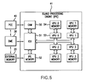
- FIG. 5 is a block level diagram further illustrating in one embodiment the parallel LCP solver of the present invention.
- FIG. 6 is a flowchart illustrating an exemplary method of operation for the parallel LCP solver of the present invention
- FIG. 7 conceptually illustrates (in part) the formation of a constraint row
- FIG. 8 is flowchart illustrating an exemplary computational method susceptible to execution on the parallel LCP solver of the present invention.
- the present invention is described in the context of a hardware architecture designed to efficiently run a computational method adapted to resolve LCPs using a plurality of parallel execution units.
- run refers to any hardware/software interaction, whereby one or more logic steps identified by the software are executed using the hardware.
- Any operative combination of hardware elements, comprising at least the plurality of parallel execution units, that enables execution of a competent computational method resolving LCPs will hereafter be referred to as a “parallel LCP solver.”
- the parallel LCP solver of the present invention may take many physical forms, including, as examples, a stand-alone circuit, a circuit integrated with a general processor, a single integrated circuit (IC) chip, a set of IC chips, or a subsystem of a dedicated processor implemented on a PCI expansion board. Any one of a number of computational methods may be run on the parallel LCP solver proposed by the present invention. Indeed, certain conventional computational methods may be adapted to efficiently run on hardware designed in accordance with the present invention.
- the parallel LCP solver will run a computational method such as the one described in commonly assigned and concurrently filed U.S. patent application Ser. No. 10/793,899.
- This application describes a novel computational method (hereafter, the “improved method”) adapted to resolve complex LCPs without the disabilities associated with conventional computational methods.
- the improved method is described in the referenced application in the context of a projected iterative descent, namely a projected Gauss-Seidel method.
- a brief background discussion of this improved method will further illuminate the written description of the present invention that follows, and facilitate an understanding of the first embodiment.
- the improved method is characterized in one aspect by the definition and use of data forms providing efficient resolution of LCPs derived from physics-based problems.
- physics-based problems necessarily arise when a display system such as a Personal Computer (PC) seeks to incorporate realistic physical qualities into a displayed animation or simulation.
- LCPs are a common way of mathematically expressing these physics-based problems, but there a variations in the type and quality of data forms used within the LCPS. Properly selected data forms are easier to store and transfer between the logic units executing operations associated with a computational method running on the parallel LCP solver.
- the improved method is also characterized by the use of simplified computational operations.
- Conventional computational methods often require large matrix/vector multiplication operations.
- the improved method replaces such complex operations with more efficient ones, such as scaled vector additions.
- the improved method is able to run in real-time while providing accurate resolution of LCPs.
- FIG. 2 is a conceptual illustration of a system incorporating a PPU 10 .
- the system otherwise comprises a general processor, denoted as a Central Processing Unit (CPU) 1 , an external memory 2 , and one or more peripherals 3 , including a display device.
- CPU Central Processing Unit
- peripherals 3 including a display device.
- a Graphics Processing Unit (GPU) 9 is also routinely associated with the system.
- PPU 10 is connected to a dedicated external memory 20 .
- Dedicated external memory 20 is preferred since the conventional memory 2 normally associated with CPU 1 is not configured to provide the data bandwidth and data throughput presently contemplated by the architecture of a system incorporating PPU 10 .
- PPU 10 need not be universally configured with its own dedicated, external memory 20 . It is very possible that PPU 10 might share an external memory with GPU 9 and/or CPU 1 .
- connections between PPU 10 and the other components in system 7 comprise, for example, a USB2 connection 35 , a IEEE 1394 (Firewire) connection 36 , and/or one or more of several PCI Interfaces 34 , including as examples, PCI, PCI-X, and/or PCI-Express.
- PPU 10 also includes an asynchronous serial interface 31 which allows debugging over an RS-232 link, additional general purpose I/Os 30 provided for low level debugging and status reporting, and/or an IEEE 1149.1 (JTAG) interface 32 provided for the debugging of software running on the PPU 10 .
- JTAG IEEE 1149.1
- PPU 10 may be incorporated using a standard PC Interface (PCI) card where system 7 is a PC, game console, or similar device having PCI expansion slots.
- PCI PC Interface
- a PCI-Express Interface card might be used.
- a USB2 or Firewire connection to an externally packaged PPU module might be used instead of an internally configured interface card.
- a PPU and a GPU will be combined on a single interface card. That is, both chips will be physically mounted on the same card (AGP or PCI-Express), but not directly interfaced with one another.
- a single interface card having a directly interfaced PPU-GPU combination is expected, but such a combination is probably a generation away. So too is a combination within a single chip of PPU and CPU functionalities.
- the improved method is iterative in nature, i.e., sequentially computing on a working constraint row by working constraint row basis, where each working constraint row computation is predicated upon previously computed constraint row values.
- the projected, iterative descent method presently preferred requires the use of previously computed results as soon as they are available.
- f i X+1 can be calculated independent from f j X+1 as computed for all constraint rows j ⁇ i. This computationally independent relationship allows for parallel execution.
- This relationship may be expressed in mathematically terms as: ⁇ v I(i,1) , v I(i,2) ⁇ v I(j,1) , v I(j,2) ⁇ (2). Stated more literally, there is no intersection between a set of auxiliary variables, ⁇ v I(i,1) , v I(i,2) ⁇ , defined in accordance with a selected coupling invariant for a working constraint row i and a corresponding set of auxiliary variables, ⁇ v I(i,1) , v I(i,2) ⁇ , for a previously considered constraint row j.
- equation (2) is expressed alternatively as ⁇ I(i, 1 ), I(i, 2 ) ⁇ I(j, 1 ), I(j, 2 ) ⁇ , a more intuitive physical meaning may be discerned, namely constraint row i and constraint row j are related to different object pairs.
- sequence of constraints influencing an island (i.e., a grouping) of objects is typically generated in a random manner by conventional collision detection routines. Collision detection is a common precursor step to the resolution of rigid body dynamics. Thus, a random order appearance (and subsequent random resolution) of constraints defining the LCP should not have a negative influence on convergence.
- rigid body island is used hereafter to refer to any set of rigid bodies directly or indirectly connected one to another by one or more constraints.
- the resulting collection of object-related data and constraint-related data is referred to as an “island data set.”
- the dynamics of an individual rigid body island may be resolved using a separate LCP.
- an island data set defines a whole gradient vector expressed by the LCP.
- the island data set (whole gradient vector) will divided into multiple subspaces for resolution by the parallel hardware architecture of the present invention.
- FIG. 4 is a functional block diagram illustrating an exemplary data transfer and logic control relationship between components within the PPU of FIG. 2 .
- Overall control of PPU 10 may be directed from CPU 1 .
- PPU 10 will include a PPU Control Engine (PCE) 40 adapted to control most, if not all, PPU operations.
- PCE PPU Control Engine
- DME Data Movement Engine
- DME 38 is connected to system 7 and external memory 20 .
- PPU 10 further comprises a plurality of Island Processing Engines (IPE).
- IPE Island Processing Engines
- Each IPE is preferably a vector processor, but may take many other forms in accordance with particular design considerations. In the present example, only four IPEs 41 , 42 , 43 , and 44 are illustrated for the sake of clarity. However, it is presently contemplated that more than four IPEs may be used within PPU 10 .
- Main application 4 (see, FIG. 1 ) running on system 7 will generate an initial physics-based data set.
- This “initial data set” will vary in size and composition according to the exact nature of the physics-based animation to be displayed. However, the initial data set will typically be derived from a body mass array defining the mass and/or moment of inertia for objects in the animation, and a constraint data array defining constraints acting upon the respective objects.
- LCP-related data components include, as examples and without limitation, Jacobian(s) related to the initial data; initial forces, if any, acting on the objects; system matrix A, matrix splittings, diagonals, etc.
- Jacobian(s) related to the initial data
- initial forces if any, acting on the objects
- system matrix A matrix splittings, diagonals, etc.
- the preferred improved method does not require explicit calculation and storage of system matrix A. This may not be true for other selected computational methods.
- the initial data set is augmented with the calculation results.
- the initial data set is transferred to the PPU via a competent physical connection by means of a conventional data transfer protocol. Transfer of the initial data set from one or more components in system 7 to PPU 10 may take place as a single block transmission, or as a sequence of related data block transmissions.
- PCE 40 After receiving the initial data set, PCE 40 defines one or more island data sets from the initial data set, and thereafter distributes a island data set to each respective IPE. As presently preferred, this is the first moment at which LCP-related data components like the Jacobian are required to construct a LCP from each respective island set. Accordingly, many, if not all, of the LCP-related data components will be calculated in an IPE.
- the definition of one or more island data sets may be performed by CPU 1 .
- IPE 41 comprises a conventionally constructed Island Control Unit (ICU) 51 communicating at least data transfer commands to/from DME 38 , and generally directing the transfer of data between an IPE memory 52 and a plurality of execution units. ICU 51 also directs the transfer of between external memory 20 and IPE memory 52 . IPE 41 further comprises in this particular teaching example a Content Addressable Memory (CAM) 50 , and a plurality of Vector Processing Units (VPUs), each having an associated VPU memory. As presently preferred, each VPU is formed from a combination of conventional elements including at least one circuit executing floating point operations.
- Vector-type processors are presently preferred for the execution of mathematical operations, such as floating point operations, within an IPE.
- the parallel-arranged and computationally-related circuits within each IPE need not be vector type processors, and are generically referred to hereafter as a “plurality of execution units.”
- each execution unit in the plurality of execution units will receive some portion of data from the island data set and resolve said “data portion” in parallel with the other execution units.
- VPU 53 and its associated VPU memory 54 are numerically identified.
- the choice of four VPUs in the current example is merely illustrative.
- the plurality of execution units provided by the plurality of IPEs will perform a great majority of the mathematical computations inherent in the resolution of physics-based animations. Accordingly, PCE 40 , and the associated plurality of ICUs do not need to provide a great deal of computational power.
- CAM 50 is a conventional circuit that functions as a type of specialized memory.
- ICU 51 logically controls and arbitrates the distribution of constraint rows from IPE memory 52 to a selected one of the plurality of executions units in accordance with data stored in CAM 50 . That is, an island data set is transferred to IPE memory 52 from external memory 20 or directly from system 7 .
- the island data set comprises a large collection of constraint rows defining the rigid body island.
- data corresponding to a selected group of constraint rows is transferred from IPE memory 52 to a selected execution unit memory, e.g., VPU memory 54 . Thereafter, the grouping or “subspace” of constraint rows is resolved in the corresponding execution unit.
- Appropriate constraint row distribution by ICU 51 in conjunction with CAM 50 ensures that for any two constraint rows i ⁇ j, f i X+1 and f j X+1 are calculated simultaneously if they satisfy the relationship ⁇ I(i, 1 ), I(i, 2 ) ⁇ I(j, 1 ), I(j, 2 ) ⁇ , subject to certain exceptions explained hereafter. For ease of reference, this relationship will be referred to hereafter as “the first parallelization condition.” Additionally, “a second parallelization condition” is also imposed, namely the most current values for ⁇ v I(i,1) , v I(i,2) ⁇ are used to calculate each f i X+1 .
- ICU 51 The inter-operation of ICU 51 , CAM 50 and respective execution units is further illustrated in relation to the exemplary computational method illustrated in Pseudo-code example 1 below.
- max_u
- an index of data entries controlled by CAM 50 is defined in accordance with an unique object identifier (ID) attached to each object in the initial data set.
- ID an exemplary data entry in CAM 50 is presently defined by one byte of data in which bits 7 and 8 indicate an associated execution unit (VPU), bit 5 is the “cur_v tag”value, bit 4 is the “new_v_tag” value, and bits 3 , 2 , 1 , and 0 are used to indicate the number of constraints (joints and/or contacts) that yet require the use of an auxiliary variable v associated with the object.
- This auxiliary variable is denoted v index .
- This approach provides an internal counter of sorts that tracks whether a particular auxiliary variable, now stored in an execution unit's memory, is still required by an execution unit for some ongoing computation, or whether the auxiliary variable is no longer needed and may be transferred back to IPE memory 52 for future use.
- Table 2 is a truth table describing all possible processing actions for any given CAM access.
- CAM 50 is cleared, and all memory entries are made available for storing an object ID. Thereafter, IPE 41 processes a collection of constraint rows according to a predefined sequence. The following example teaches CAM operation within this process.
- a first CAM entry is made for the first object having an ID value of “2.” Assuming the preferred, 8-bit CAM entry data structure described above, the first CAM entry looks like this:
- a second CAM for the second object having an ID value of “1” looks like this:
- VPU 00 Since row filtering has been disabled in the current working example, a value of “1” is written for bit 5 in each CAM entry. At this time, the first execution unit, VPU 00, has data corresponding to constraint row 1 stored in its associated memory, and VPU 01 is still idle.
- ICU 52 will forward data corresponding to constraint row 2 to the first execution unit VPU 00, and update CAM entry 2 for object “1”, since the first execution unit VPU 00, will now use a common auxiliary value v 1 in the calculation of constraint rows 1 and 2 .
- Corresponding CAM entries for Step 2 are shown below.
- VPU 00 has constraint rows 1 and 2 stored in its associated memory.
- VPU 01 remains idle.
- constraint rows 1 and 2 do not satisfy the first parallelization condition, ⁇ I(i, 1 ), I(i, 2 ) ⁇ I(j, 1 ), I(j, 2 ) ⁇ , since they share a common object “1”.
- this fact does not contradict the previous conclusion or recommendation regarding conditions placed upon the distribution of constraint rows between a plurality of execution units.
- each respective VPU memory forms a cache for auxiliary variable(s).
- VPU 00 stores constraint rows 1 and 2 in its memory
- VPU 01 stores constraint row 3 .
- VPU 01 Data corresponding to constraint row 4 is forwarded to VPU 01, since VPU 01 already contains a constraint row related to object “5”. At this time, VPU 00 stores constraint rows 1 and 2 in its memory, and VPU 01 stores constraint rows 3 and 4 . Of note, there are no constraint rows stored in VPU 00 and VPU 01 that relate to a common object. Therefore, the first parallelization condition is satisfied.
- Constraint row 5 the only “skipped” constraint row in the simple working example, is processed in a subsequent iteration after all the constraints rows successfully distributed to execution units have been processed. Once these distributed constraint rows are resolved, it is highly likely that constraint row 5 will be able to be processed without difficulty. Stated in other terms, objects “1” and “4”, which are already stored in different execution units by the time the constraint row distribution process reaches constraint row 5 , form a competing object pair for constraint row 5 . With resolution of stored constraint rows 1 through 4 , the corresponding CAM entries will be released, and constraint row 5 will accordingly be susceptible to proper distribution.
- VPU 00 and VPU 01 would both contain constraint rows associated with one or more common objects.
- the respective execution units will begin processing data as soon as constraint row(s) are distributed by inter-operation of the ICU and CAM. As soon as a constraint row is processed, the execution unit notifies the ICU to update the corresponding CAM entries.
- update of the corresponding CAM entries decreases the “number of constraints using v A ” and “number of constraints using v B ” by 1, respectively.
- a “number of constraints using v index ” value for a particular CAM entry reaches zero, the corresponding auxiliary variable is not needed (i.e., bound up with) the resolving execution unit. Accordingly, data corresponding to the auxiliary variable may be transferred from the execution unit to the IPE memory for subsequent transfer to another execution unit, as needed.
- constraint row 5 is readily resolved following resolution of constraint rows 2 and 3 .
- FIG. 6 is a flowchart illustrating an exemplary method of operation for a parallel LCP solver finding application, for example, in a rigid body dynamics simulator.
- a system processor either CPU or PPU
- the one or more island data sets are distributed to a plurality of IPEs ( 60 ).
- IPEs i.e. execution units
- each VPU will thereafter calculate a corresponding Jacobian for the object or constraint ( 62 ).
- constraint rows and associated Jacobians are distributed across the plurality of VPUs ( 63 ), and thereafter solved ( 64 ).
- the resulting calculations are changes to the velocities (u) and forces (f) influencing the movement of the objects defined in the island data group.
- the present invention preferably calculates force changes. Strictly speaking, the “force” calculations in the preferred embodiment are not real constraint force(s)/torque(s), but Lagrange multipliers.
- the real constraint force(s)/torque(s) are determined by the multiplying the calculated change in force “f” by a corresponding Jacobian. Once the constraint force(s)/torque(s) are obtained, an integration process (i.e. an ordinary differential equation (“ODE”) calculation) is performed to update the positions, orientations, linear velocities, and angular velocities for objects in an island data set.
- ODE ordinary differential equation
- both the constraint force/torque calculation(s) and ODE integration process(es) are performed in parallel in the PPU. This is especially true for the constraint force/torque calculation(s) which are used in the CAM-based constraint row distribution scheme described above.
- CAM entries are updated ( 65 ). Consistent with the foregoing description, the appropriate values for “number of constraints using v index are decreased, and if zero, the corresponding v index will be read back from the resolving VPU to the IPE memory and the CAM entry will be clearly.
- ODE Ordinary Differential Equation
- the present invention is further illustrated in the following alternate embodiment. It begins with the selection of a computational method competent to solve physics-based LCPs, namely a steepest descent method. This method is routinely used to solve linear equations.
- the base equation may be expressed as a function:
- f ⁇ ( x n ⁇ 1 ) 1 2 ⁇ x n ⁇ 1 T ⁇ A n ⁇ n ⁇ x n ⁇ 1 - b n ⁇ 1 T ⁇ x n ⁇ 1 .
- the steepest descent method begins by making an initial guess at the solution vector x, and thereafter iteratively modifying x until f(x) can not be further reduced. At each iteration, the method seeks to move x linearly in a direction that provides the greatest reduction in the value of f′(x).
- x n ⁇ 1 ( k + 1 ) x n ⁇ 1 ( k ) - ⁇ ⁇ ⁇ f ⁇ ′ ⁇ ( x n ⁇ 1 k ) . This process is repeated until f′(x k ) is sufficiently close to zero.
- x n ⁇ 1 ( k + 1 ) mid ⁇ ( lo , x n ⁇ 1 ( k ) - ⁇ ⁇ ⁇ f ⁇ ′ ⁇ ( x n ⁇ 1 k ) , hi ) , where the “mid” function selects the median element for each constraint row.
- the whole space may be thought of as a collection of data matrices defined from the physics-based data set. As illustrated in FIG. 7 , for only an exemplary group of associated matrices defining the whole space, a row-wise association of data elements forms constraint row 70 . Constraint rows influencing a common object are termed “neighbored constraint rows.”
- the present invention avoids the computational difficulties associated with descending over the whole space by dividing the whole space into selected subspaces. Once selected subspaces have been defined, a competent computational method is applied and descends along each one of the selected subspace. Subspaces are selected at the beginning of each general iteration of the computational method based on the relative change (i.e., steepness) of each subspace during the current iteration. “Greatest relative change” may be determined in many ways, such as by locating the constraint row in the whole space having the highest velocity value, u. By sequentially selecting the “next” subspace to-be-resolved during a particular iteration on the basis of its greatest relative change, the present invention effectively descends along (resolves) the subspace most likely to affect the physics-based animation.
- each object having during any given iteration from zero to m constraints affecting it. That is, each object may be affected by zero or more constraints during a particular iteration, where each constraint defines one or more constraint rows within the island data set.
- the island data set is subjected to an initial preprocessing step ( 80 ) once received in IPE memory 52 .
- Preprocessing includes a definition of initial subspaces in accordance with object/constraint connectivity relationships expressed in the island data set.
- subspaces are formed by grouping “associated constraint rows” in relation to a common object.
- Associated constraint rows are preferably, but necessarily, grouped such that all constraint rows arising from the same constraint are placed in the same subspace. This is particularly true for all constraint rows arising from a frictional contact between objects.
- data associated with each initial subspace is pre-distributed to a corresponding VPU memory ( 81 ).
- the corresponding VPU thereafter calculates corresponding Jacobian(s) for the initial subspace ( 82 ).
- the subspace data and calculated Jacobians are stored in IPE memory 52 and/or a selected VPU memory. Then, an iteration time step value of 0 is assumed ( 83 ).
- a general iteration process begins ( 84 ).
- the VPU calculates an “object steepness” which is equal to the greatest relative change value for constraint rows associated with an object in the subspace ( 85 ).
- IPU 52 generates a number of subspaces, up to the maximum number of available execution units, to be resolved during a “current” iteration ( 87 ).
- Subspaces to-be-resolved are sequentially identified in accordance with a “greatest object steepness.” Neighbored constraint rows associated with an object having the greatest object steepness are grouped into a common subspace wherever possible. The maximum number of grouped rows in a subspace will be determined by such factors as the rate of iteration time step, memory bandwidth capabilities, etc.
- each constraint row and object appear in only one subspace.
- constraint rows and objects are listed, using one of many conventional techniques, within each island data set, and marked off the list when grouped into a particular subspace.
- Each constraint row should be grouped with its neighbored constraint rows, unless a neighbored constraint row has already been marked off the list.
- an object associated with a constraint row may be included in a subspace only if it has not previously been included in another subspace. Omission of a constraint row or object from a particular subspace is usually not a problem since it is likely to be included in a subspace resolved during the next iteration.
- Jacobian and Mass matrix data associated with the object(s) and constraint(s) in the subspace are also transferred from IPE memory 52 to a memory associated with the execution unit under the control of ICU 51 ( 88 ). With this data appropriately distributed, the plurality of execution units solve in parallel the plurality of subspaces using a competent computational method ( 89 ).
- the present invention seeks to simultaneously resolve multiple selected subspaces, where each selected subspace contains a sequentially determined greatest object steepness.
- This approach suggests two implementation considerations. First, respective subspaces should be defined by their constituent constraint rows so as to minimize inter-subspace influences. That is, wherever possible, resolution of a subspace should not depend upon the resolution of a constraint row included in another subspace. Second, where the foregoing consideration is observed, the parallel computational scheme afforded by the present invention will run in a linear manner. That is, the speed of LCP convergence will be increased with the number of parallel execution units applied to the problem.
- LCP resolution by subspace affords some interesting processing options.
- LCP resolution has been assigned to one and only one computational method or algorithm. That is, a single computational method is selected and consistently applied regardless of the particular nature of the physics-based data set, or objects within the data set.
- the present invention affords the designer of a parallel LCP solver with many advantages. For example, performance and accuracy may be traded-off by adjustments to the size of iteration steps and convergence thresholds.
- the parallel architecture of the present invention may be applied to single CPU platforms such as PCs, multiple CPU platforms such as game consoles, and systems incorporating a dedicated PPU running in cooperation with a system CPU.
- Parallel resolution of subspaces derived from a whole gradient vector defining an LCP allow for real-time resolution of the LCP.
- Such real-time resolution provides enhanced visual effects to a main application incorporating physic-based animation features, such as rigid body dynamics.
Abstract
Description
-
-
Step 0—Initialization: Define fO to be an arbitrary vector that lies within a feasible region defined between limits lo and hi, (lo<f0<hi), as an initial candidate solution f0 for an initial iteration; -
Step 1—General Iteration: Solve the LCP (b+CfX,A) by defining a subsequent candidate solution fX+1 for an iteration X+1, such that the subsequent candidate solution fX+1 is always closer to a final solution for the LCP than a previous candidate solution fX, for all fX greater than zero; and, -
Step 2—Test for Termination: Determine whether fX+1 satisfies a prescribed stopping rule, and if “Yes” terminate, but if “No” return to step 1 for another iteration, i.e., X→X+1.
-
{v I(i,1) , v I(i,2) }∩{v I(j,1) , v I(j,2)}≡Φ (2).
Stated more literally, there is no intersection between a set of auxiliary variables, {vI(i,1), vI(i,2)}, defined in accordance with a selected coupling invariant for a working constraint row i and a corresponding set of auxiliary variables, {vI(i,1), vI(i,2)}, for a previously considered constraint row j. That is, no common or shared elements exist for {vI(i,1), vI(i,2)} and {vI(j,1), vI(j,2)}. If equation (2) is expressed alternatively as {I(i,1), I(i,2)}∩{I(j,1), I(j,2)}≡Φ, a more intuitive physical meaning may be discerned, namely constraint row i and constraint row j are related to different object pairs.
| Initialize: f, v, x = 0, 0, 0 and new_v_tag = 1 |
| while (1) |
| i = 0 |
| max_u = 0 |
| cur_v_tag = new_v_tag | // Remember tags from last (i.e. previous) time step |
| new_v_tag = 0 | // Clear tags for current time step |
| do i ≠ m |
| if !(cur_v_tag[I(i,1)] ∥ cur_v_tag[I(i,2)]) | // If both the two objects have | |
| continue to next i=i+1 | small changes, skip this row | |
| end if |
| ui = bi + JQi1 C · vI(i,1) + JQi2 C · vI(i,2) | |
| newf := med(loi,fi − aii −1 * ui,hii) | |
| Δv = (newf − fi)(JQi1 C)T |
| if ∥Δv∥∞ > Thres | // Check if object I(i,1)'s v has big change? |
| new_v_tag[I(i,1)] = 1 | |
| end if |
| vI(i,1) := vI(i,1) + Δv | |
| Δv = (newf − fi)(JQi2 C)T |
| if ∥Δv∥∞ > Thres | // Check if object I(i,2)'s v has big change? | |
| new_v_tag[I(i,2)] = 1 | ||
| end if |
| vI(i,2) := vI(i,2) + Δv | |
| fi := newf |
| // Check the LCP boxing conditions |
| if(fi = loi |
| if (|ui| > max_u) | // If boxing conditions not satisfied, check max |ui| | |
| max_u = |ui| | ||
| end if |
| // Despite not satisfying conditions, calculate the row in next time step |
| new_v_tag[I(i,1)] = 1 | |
| new_v_tag[I(i,2)] = 1 | |
| end if | |
| end do |
| if (max_u < Thres) | // If max_u is less than threshold, method converges |
| break /* algorithm ends */ |
| endif |
| end while |
| TABLE 1 | ||
| Constraint | The first object ID | The second object ID |
| row number | A = I(i, 1) | B = I(i, 2) |
| 1 | 2 | 1 |
| 2 | 1 | 3 |
| 3 | 5 | 4 |
| 4 | 5 | 6 |
| 5 | 1 | 4 |
| TABLE 2 | ||||
| (VPU ID, | ||||
| cur_v_tag) | xx1 | xx0 | aa1 | aa0 |
| xx1 | Forward row to least busy | Forward row to least busy | Forward vB to VPU aa; Create a CAM entry for body B |
| VPU; Create CAM entries | VPU; Create CAM entries | ||
| for A & B | for A & B |
| xx0 | Forward row to least busy | Skip constraint row | Forward vB to VPU aa; Create | Skip constraint row until next |
| VPU; Create CAM entries | until next iteration | CAM entry for body B | iteration | |
| for A & B | ||||
| bb1 | Forward vA to VPU bb; | Forward vA to | Skip constraint row until next | Skip constraint row until next |
| Create CAM entry for body B | VPU bb, Create CAM | iteration; Try in the same | iteration; Try in the same | |
| entry for body B | iteration if aa != bb; | iteration if aa != bb; | ||
| Otherwise, forward to VPU | Otherwise, forward to VPU | |||
| aa, i.e. bb. | aa, i.e. bb. | |||
| bb0 | Skip constraint row | Skip constraint row until next | Skip constraint row until next | |
| until next iteration | iteration; Try in the same | iteration | ||
| iteration if aa != bb; | ||||
| Otherwise, forward to VPU | ||||
| aa, i.e. bb. | ||||


Since row filtering has been disabled in the current working example, a value of “1” is written for


At this time, VPU 00

Data corresponding to
The minimum of this function occurs when its derivative is zero, or
f(x n×1)=A n×n ·x n×1 b=0.
Thus, if for a selected vector x (i.e., a self-variant x), f(x) reaches a minimum (or its first derivative equals zero), then the selected vector x is a solution to the base equation.
This process is repeated until f′(xk) is sufficiently close to zero.
where the “mid” function selects the median element for each constraint row.
Claims (25)
Priority Applications (3)
| Application Number | Priority Date | Filing Date | Title |
|---|---|---|---|
| US10/815,721 US7421303B2 (en) | 2004-01-22 | 2004-04-02 | Parallel LCP solver and system incorporating same |
| PCT/US2004/030692 WO2005074425A2 (en) | 2004-01-22 | 2004-09-20 | Parallel lcp solver and system incorporating same |
| TW093129558A TW200525374A (en) | 2004-01-22 | 2004-09-30 | Parallel LCP solver and system incorporating same |
Applications Claiming Priority (2)
| Application Number | Priority Date | Filing Date | Title |
|---|---|---|---|
| US53792004P | 2004-01-22 | 2004-01-22 | |
| US10/815,721 US7421303B2 (en) | 2004-01-22 | 2004-04-02 | Parallel LCP solver and system incorporating same |
Publications (2)
| Publication Number | Publication Date |
|---|---|
| US20050165874A1 US20050165874A1 (en) | 2005-07-28 |
| US7421303B2 true US7421303B2 (en) | 2008-09-02 |
Family
ID=34798882
Family Applications (1)
| Application Number | Title | Priority Date | Filing Date |
|---|---|---|---|
| US10/815,721 Active 2026-04-06 US7421303B2 (en) | 2004-01-22 | 2004-04-02 | Parallel LCP solver and system incorporating same |
Country Status (2)
| Country | Link |
|---|---|
| US (1) | US7421303B2 (en) |
| TW (1) | TW200525374A (en) |
Cited By (14)
| Publication number | Priority date | Publication date | Assignee | Title |
|---|---|---|---|---|
| US20050075849A1 (en) * | 2003-10-02 | 2005-04-07 | Monier Maher | Physics processing unit |
| US20050075154A1 (en) * | 2003-10-02 | 2005-04-07 | Bordes Jean Pierre | Method for providing physics simulation data |
| US20050086040A1 (en) * | 2003-10-02 | 2005-04-21 | Curtis Davis | System incorporating physics processing unit |
| US20050251644A1 (en) * | 2004-05-06 | 2005-11-10 | Monier Maher | Physics processing unit instruction set architecture |
| US20060149516A1 (en) * | 2004-12-03 | 2006-07-06 | Andrew Bond | Physics simulation apparatus and method |
| US20060265202A1 (en) * | 2005-05-09 | 2006-11-23 | Muller-Fischer Matthias H | Method of simulating deformable object using geometrically motivated model |
| US20080282058A1 (en) * | 2007-05-10 | 2008-11-13 | Monier Maher | Message queuing system for parallel integrated circuit architecture and related method of operation |
| US20090315885A1 (en) * | 2008-06-18 | 2009-12-24 | Roblox Corporation | Method and apparatus for automatic coalescence of connected rigid bodies |
| US7937359B1 (en) * | 2004-03-08 | 2011-05-03 | Nvidia Corporation | Method of operation for parallel LCP solver |
| US20110153870A1 (en) * | 2009-12-18 | 2011-06-23 | Seagate Technology Llc | Advanced processing data storage device |
| US8731880B2 (en) | 2010-09-14 | 2014-05-20 | University Of Washington Through Its Center For Commercialization | Invertible contact model |
| US11471232B2 (en) | 2012-08-03 | 2022-10-18 | Stryker Corporation | Surgical system and method utilizing impulse modeling for controlling an instrument |
| US11639001B2 (en) | 2012-08-03 | 2023-05-02 | Stryker Corporation | Robotic system and method for reorienting a surgical instrument |
| US11672620B2 (en) | 2012-08-03 | 2023-06-13 | Stryker Corporation | Robotic system and method for removing a volume of material from a patient |
Families Citing this family (12)
| Publication number | Priority date | Publication date | Assignee | Title |
|---|---|---|---|---|
| US7353149B2 (en) * | 2001-04-25 | 2008-04-01 | Telekinesys Research Limited | Method and apparatus for simulating dynamic contact of objects |
| US7363199B2 (en) * | 2001-04-25 | 2008-04-22 | Telekinesys Research Limited | Method and apparatus for simulating soft object movement |
| US7620530B2 (en) * | 2004-11-16 | 2009-11-17 | Nvidia Corporation | System with PPU/GPU architecture |
| US20070067517A1 (en) * | 2005-09-22 | 2007-03-22 | Tzu-Jen Kuo | Integrated physics engine and related graphics processing system |
| US8666712B2 (en) * | 2006-07-24 | 2014-03-04 | Ati Technologies Inc. | Physical simulations on a graphics processor |
| US7933858B2 (en) * | 2007-03-23 | 2011-04-26 | Autodesk, Inc. | General framework for graphical simulations |
| US8223155B2 (en) * | 2007-04-27 | 2012-07-17 | Sony Corporation | Method for simulating large numbers of spherical bodies interacting |
| JP5240196B2 (en) * | 2007-07-12 | 2013-07-17 | 富士通株式会社 | Calculation apparatus, calculation method, and calculation program |
| US8279227B2 (en) * | 2008-04-04 | 2012-10-02 | Sony Corporation | Method for detecting collisions among large numbers of particles |
| JP5417865B2 (en) * | 2009-01-28 | 2014-02-19 | 富士ゼロックス株式会社 | Particle behavior analysis apparatus and program |
| US9063882B1 (en) * | 2010-09-09 | 2015-06-23 | Sas Ip, Inc. | Matrix preconditioners for simulations of physical fields |
| US10885242B2 (en) * | 2017-08-31 | 2021-01-05 | Microsoft Technology Licensing, Llc | Collision detection with advanced position |
Citations (6)
| Publication number | Priority date | Publication date | Assignee | Title |
|---|---|---|---|---|
| US5938530A (en) * | 1995-12-07 | 1999-08-17 | Kabushiki Kaisha Sega Enterprises | Image processing device and image processing method |
| US5966528A (en) * | 1990-11-13 | 1999-10-12 | International Business Machines Corporation | SIMD/MIMD array processor with vector processing |
| US20030179205A1 (en) * | 2000-03-10 | 2003-09-25 | Smith Russell Leigh | Image display apparatus, method and program based on rigid body dynamics |
| US20040062443A1 (en) * | 2002-10-01 | 2004-04-01 | Jonathan Yen | Extracting graphical bar codes from an input image |
| US20040075623A1 (en) * | 2002-10-17 | 2004-04-22 | Microsoft Corporation | Method and system for displaying images on multiple monitors |
| US7075541B2 (en) * | 2003-08-18 | 2006-07-11 | Nvidia Corporation | Adaptive load balancing in a multi-processor graphics processing system |
-
2004
- 2004-04-02 US US10/815,721 patent/US7421303B2/en active Active
- 2004-09-30 TW TW093129558A patent/TW200525374A/en unknown
Patent Citations (6)
| Publication number | Priority date | Publication date | Assignee | Title |
|---|---|---|---|---|
| US5966528A (en) * | 1990-11-13 | 1999-10-12 | International Business Machines Corporation | SIMD/MIMD array processor with vector processing |
| US5938530A (en) * | 1995-12-07 | 1999-08-17 | Kabushiki Kaisha Sega Enterprises | Image processing device and image processing method |
| US20030179205A1 (en) * | 2000-03-10 | 2003-09-25 | Smith Russell Leigh | Image display apparatus, method and program based on rigid body dynamics |
| US20040062443A1 (en) * | 2002-10-01 | 2004-04-01 | Jonathan Yen | Extracting graphical bar codes from an input image |
| US20040075623A1 (en) * | 2002-10-17 | 2004-04-22 | Microsoft Corporation | Method and system for displaying images on multiple monitors |
| US7075541B2 (en) * | 2003-08-18 | 2006-07-11 | Nvidia Corporation | Adaptive load balancing in a multi-processor graphics processing system |
Cited By (25)
| Publication number | Priority date | Publication date | Assignee | Title |
|---|---|---|---|---|
| US20050075849A1 (en) * | 2003-10-02 | 2005-04-07 | Monier Maher | Physics processing unit |
| US20050075154A1 (en) * | 2003-10-02 | 2005-04-07 | Bordes Jean Pierre | Method for providing physics simulation data |
| US20050086040A1 (en) * | 2003-10-02 | 2005-04-21 | Curtis Davis | System incorporating physics processing unit |
| US7895411B2 (en) | 2003-10-02 | 2011-02-22 | Nvidia Corporation | Physics processing unit |
| US7739479B2 (en) | 2003-10-02 | 2010-06-15 | Nvidia Corporation | Method for providing physics simulation data |
| US7937359B1 (en) * | 2004-03-08 | 2011-05-03 | Nvidia Corporation | Method of operation for parallel LCP solver |
| US20050251644A1 (en) * | 2004-05-06 | 2005-11-10 | Monier Maher | Physics processing unit instruction set architecture |
| US9440148B2 (en) | 2004-12-03 | 2016-09-13 | Telekinesys Research Limited | Physics simulation apparatus and method |
| US8437992B2 (en) | 2004-12-03 | 2013-05-07 | Telekinesys Research Limited | Physics simulation apparatus and method |
| US7788071B2 (en) * | 2004-12-03 | 2010-08-31 | Telekinesys Research Limited | Physics simulation apparatus and method |
| US20100299121A1 (en) * | 2004-12-03 | 2010-11-25 | Telekinesys Research Limited | Physics Simulation Apparatus and Method |
| US20060149516A1 (en) * | 2004-12-03 | 2006-07-06 | Andrew Bond | Physics simulation apparatus and method |
| US20110077923A1 (en) * | 2004-12-03 | 2011-03-31 | Telekinesys Research Limited | Physics simulation apparatus and method |
| US7650266B2 (en) | 2005-05-09 | 2010-01-19 | Nvidia Corporation | Method of simulating deformable object using geometrically motivated model |
| US20060265202A1 (en) * | 2005-05-09 | 2006-11-23 | Muller-Fischer Matthias H | Method of simulating deformable object using geometrically motivated model |
| US20080282058A1 (en) * | 2007-05-10 | 2008-11-13 | Monier Maher | Message queuing system for parallel integrated circuit architecture and related method of operation |
| US7627744B2 (en) * | 2007-05-10 | 2009-12-01 | Nvidia Corporation | External memory accessing DMA request scheduling in IC of parallel processing engines according to completion notification queue occupancy level |
| US20090315885A1 (en) * | 2008-06-18 | 2009-12-24 | Roblox Corporation | Method and apparatus for automatic coalescence of connected rigid bodies |
| US8537165B2 (en) * | 2008-06-18 | 2013-09-17 | Roblox Corporation | Method and apparatus for automatic coalescence of connected rigid bodies |
| US20110153870A1 (en) * | 2009-12-18 | 2011-06-23 | Seagate Technology Llc | Advanced processing data storage device |
| US9575801B2 (en) | 2009-12-18 | 2017-02-21 | Seagate Technology Llc | Advanced processing data storage device |
| US8731880B2 (en) | 2010-09-14 | 2014-05-20 | University Of Washington Through Its Center For Commercialization | Invertible contact model |
| US11471232B2 (en) | 2012-08-03 | 2022-10-18 | Stryker Corporation | Surgical system and method utilizing impulse modeling for controlling an instrument |
| US11639001B2 (en) | 2012-08-03 | 2023-05-02 | Stryker Corporation | Robotic system and method for reorienting a surgical instrument |
| US11672620B2 (en) | 2012-08-03 | 2023-06-13 | Stryker Corporation | Robotic system and method for removing a volume of material from a patient |
Also Published As
| Publication number | Publication date |
|---|---|
| US20050165874A1 (en) | 2005-07-28 |
| TW200525374A (en) | 2005-08-01 |
Similar Documents
| Publication | Publication Date | Title |
|---|---|---|
| US7421303B2 (en) | Parallel LCP solver and system incorporating same | |
| US7937359B1 (en) | Method of operation for parallel LCP solver | |
| US7580821B2 (en) | Application programming interface for fluid simulations | |
| US10297066B2 (en) | Animating a virtual object in a virtual world | |
| US7079145B2 (en) | Method and program solving LCPs for rigid body dynamics | |
| Hämäläinen et al. | Online motion synthesis using sequential monte carlo | |
| US7493244B2 (en) | Computer simulation of body dynamics including a solver that solves in linear time for a set of constraints using vector processing | |
| US7739479B2 (en) | Method for providing physics simulation data | |
| US7505883B2 (en) | Computer simulation of body dynamics including a solver that solves in linear time for a set of constraints | |
| US7895411B2 (en) | Physics processing unit | |
| US7353149B2 (en) | Method and apparatus for simulating dynamic contact of objects | |
| US20050086040A1 (en) | System incorporating physics processing unit | |
| US11782500B2 (en) | System, method and apparatus of simulating physics in a virtual environment | |
| CN101154293B (en) | Image processing method and image processing apparatus | |
| US20050187742A1 (en) | Physics engine | |
| US20020118197A1 (en) | Collision flypapering: a method for defining realistic behavior for simulated objects in computer animation | |
| WO2005074425A2 (en) | Parallel lcp solver and system incorporating same | |
| JP2001276414A (en) | Game device and information memory medium | |
| WO2007089271A2 (en) | Application programming interface for fluid simulations | |
| NAJIM | Motion Matching with Proximal Optimization Policy | |
| Aamisepp et al. | Haptic hardware support in a 3d game engine | |
| WO2006052750A2 (en) | Asynchronous and parallel execution by physics processing unit | |
| Aliaga | Virtual and real object collisions in a merged environment | |
| Bhikharie | 3D Gaming | |
| Yeh et al. | Accelerating Real-Time Physics Simulation by Leveraging High-Level Information |
Legal Events
| Date | Code | Title | Description |
|---|---|---|---|
| AS | Assignment |
Owner name: AGEIA TECHNOLOGIES, INC., MISSOURI Free format text: ASSIGNMENT OF ASSIGNORS INTEREST;ASSIGNORS:ZHANG, LIHUA;TONGE, RICHARD;SEQUEIRA, DILIP;AND OTHERS;REEL/FRAME:015216/0432 Effective date: 20040908 |
|
| AS | Assignment |
Owner name: HERCULES TECHNOLOGY GROWTH CAPITAL, INC.,CALIFORNI Free format text: SECURITY AGREEMENT;ASSIGNOR:AGEIA TECHNOLOGIES, INC.;REEL/FRAME:016490/0928 Effective date: 20050810 Owner name: HERCULES TECHNOLOGY GROWTH CAPITAL, INC., CALIFORN Free format text: SECURITY AGREEMENT;ASSIGNOR:AGEIA TECHNOLOGIES, INC.;REEL/FRAME:016490/0928 Effective date: 20050810 |
|
| AS | Assignment |
Owner name: AGEIA TECHNOLOGIES, INC., CALIFORNIA Free format text: RELEASE BY SECURED PARTY;ASSIGNOR:HERCULES TECHNOLOGY GROWTH CAPITAL, INC.;REEL/FRAME:020827/0853 Effective date: 20080207 Owner name: AGEIA TECHNOLOGIES, INC.,CALIFORNIA Free format text: RELEASE BY SECURED PARTY;ASSIGNOR:HERCULES TECHNOLOGY GROWTH CAPITAL, INC.;REEL/FRAME:020827/0853 Effective date: 20080207 |
|
| AS | Assignment |
Owner name: NVIDIA CORPORATION, CALIFORNIA Free format text: ASSIGNMENT OF ASSIGNORS INTEREST;ASSIGNOR:AGEIA TECHNOLOGIES, INC.;REEL/FRAME:021011/0059 Effective date: 20080523 Owner name: NVIDIA CORPORATION,CALIFORNIA Free format text: ASSIGNMENT OF ASSIGNORS INTEREST;ASSIGNOR:AGEIA TECHNOLOGIES, INC.;REEL/FRAME:021011/0059 Effective date: 20080523 |
|
| STCF | Information on status: patent grant |
Free format text: PATENTED CASE |
|
| FPAY | Fee payment |
Year of fee payment: 4 |
|
| FPAY | Fee payment |
Year of fee payment: 8 |
|
| MAFP | Maintenance fee payment |
Free format text: PAYMENT OF MAINTENANCE FEE, 12TH YEAR, LARGE ENTITY (ORIGINAL EVENT CODE: M1553); ENTITY STATUS OF PATENT OWNER: LARGE ENTITY Year of fee payment: 12 |