US7420709B2 - Dither matrix generation - Google Patents
Dither matrix generation Download PDFInfo
- Publication number
- US7420709B2 US7420709B2 US10/427,766 US42776603A US7420709B2 US 7420709 B2 US7420709 B2 US 7420709B2 US 42776603 A US42776603 A US 42776603A US 7420709 B2 US7420709 B2 US 7420709B2
- Authority
- US
- United States
- Prior art keywords
- gray level
- dither
- halftone
- filter
- gray
- Prior art date
- Legal status (The legal status is an assumption and is not a legal conclusion. Google has not performed a legal analysis and makes no representation as to the accuracy of the status listed.)
- Expired - Fee Related, expires
Links
- 239000011159 matrix material Substances 0.000 title claims abstract description 49
- 238000000034 method Methods 0.000 claims abstract description 66
- 230000007704 transition Effects 0.000 claims abstract description 36
- 239000003086 colorant Substances 0.000 claims description 92
- 238000003491 array Methods 0.000 claims description 10
- 238000007639 printing Methods 0.000 claims description 9
- 230000004044 response Effects 0.000 claims description 6
- 238000006243 chemical reaction Methods 0.000 claims description 4
- 230000006870 function Effects 0.000 description 36
- 238000010586 diagram Methods 0.000 description 6
- 238000003384 imaging method Methods 0.000 description 6
- 239000002131 composite material Substances 0.000 description 4
- 230000001174 ascending effect Effects 0.000 description 3
- 238000001914 filtration Methods 0.000 description 3
- 230000008569 process Effects 0.000 description 3
- 230000008901 benefit Effects 0.000 description 2
- 230000003993 interaction Effects 0.000 description 2
- 238000007648 laser printing Methods 0.000 description 2
- 238000013139 quantization Methods 0.000 description 2
- 230000001131 transforming effect Effects 0.000 description 2
- 238000009792 diffusion process Methods 0.000 description 1
- 235000012489 doughnuts Nutrition 0.000 description 1
- 238000012986 modification Methods 0.000 description 1
- 230000004048 modification Effects 0.000 description 1
- 238000000059 patterning Methods 0.000 description 1
- 230000000007 visual effect Effects 0.000 description 1
Images


Classifications
-
- H—ELECTRICITY
- H04—ELECTRIC COMMUNICATION TECHNIQUE
- H04N—PICTORIAL COMMUNICATION, e.g. TELEVISION
- H04N1/00—Scanning, transmission or reproduction of documents or the like, e.g. facsimile transmission; Details thereof
- H04N1/40—Picture signal circuits
- H04N1/405—Halftoning, i.e. converting the picture signal of a continuous-tone original into a corresponding signal showing only two levels
- H04N1/4051—Halftoning, i.e. converting the picture signal of a continuous-tone original into a corresponding signal showing only two levels producing a dispersed dots halftone pattern, the dots having substantially the same size
Definitions
- Halftone imaging is a well-known technique for transforming a continuous tone or gray scale image (e.g., a photograph or a digital image) having picture elements or “pixels” that have tones whose values vary continuously or over a large number of discrete gray levels, into a halftone image having pixels that are either black (presence of a mark or “dot”) or white (absence of a mark or “dot”). Although the absence of a black dot can be considered a white dot, for ease of discussion, the term “dot”, as used herein, refers to the presence of a black dot.
- the halftone image creates the illusion of continuous tone. In color printers, the illusion of continuous shades of color is produced by superimposing the halftones of the individual colorants used, e.g., cyan, magenta, yellow and black (CYMK).
- Halftoning can be performed by modulating the size or amplitude of the dots, which is sometimes referred to as “amplitude modulation” or AM, or by modulating the spacing or frequency of the dots, which is sometimes referred to as “frequency modulation” or FM.
- AM and FM halftoning simultaneously modulates dot size and dot density.
- AM halftoning the viewer of the printed halftone image will perceive areas of the halftone image having larger dots to have a darker gray level than areas of the halftone image having smaller dots.
- Another halftoning technique is to transform a gray scale image to a halftone image using a dither matrix or halftone screen.
- the dither matrix consists of a two-dimensional array of elements, each having a value v ranging from 0 to (z ⁇ 1), where z represents the total number of gray levels within the gray scale range being used. For example, when using a gray scale range of 0 through 255, where 0 represents white and 255 represents black, 0 ⁇ v ⁇ 255.
- the number of elements in the dither matrix can be smaller than or equal to the number of pixels in the gray scale image to be transformed.
- the dither matrix is mapped over the gray scale image.
- the dither matrix is replicated or tiled to cover the entire gray scale image.
- Each pixel in the gray scale image is compared to a corresponding element in the halftone screen. If the gray scale image pixel has a larger or equal value, a dot is formed in the corresponding position of the halftone image, assuming an ascending gray level numbering convention is employed, i.e., where higher gray level numbers correspond to darker gray levels.
- halftone screens have been designed to achieve a pseudo-random or stochastic distribution of dots over the halftone image. Such halftone screens are sometimes referred to as “stochastic screens.”
- Some imaging devices are incapable of stably or reliably producing dots beyond a certain horizontal dot resolution.
- some laser printers operate in an enhanced resolution imaging mode, sometimes referred to as a High Definition Imaging (HDI) mode, in which the laser horizontal scan line of the normal resolution mode is subdivided into finer increments, whereby the laser print engine must produce dots during correspondingly shorter laser on/off cycles.
- HDI High Definition Imaging
- each pixel of the halftone image produced by the laser printer in the enhanced resolution mode is subdivided into sub-pixels.
- each pixel of the halftone image produced by that laser printer in the enhanced horizontal resolution mode is subdivided into 4 sub-pixels, so that the laser on/off cycle in the enhanced horizontal resolution mode is 1 ⁇ 4th the laser on/off cycle in the normal horizontal resolution mode.
- the laser printer engine may be incapable of stably or reliably printing isolated “sub-pixel dots” at that sub-pixel resolution, which results in perceptible visual anomalies or quantization noise in the resultant half-tone image produced by the laser printer.
- Such instability of the image forming device is referred to herein as “dot instability”.
- a halftone screen designed to produce a halftone image having a stochastic distribution and clustering of dots is sometimes referred to as a “clustered-dot stochastic halftone screen.”
- Clustered-dot stochastic screen designs can be used to design high quality clustered-dot stochastic screens that are moiré and pattern free, and that are also less likely to show bands, even when printing halftone images with a laser printer or other printers that have printing engines that exhibit dot-to-dot interactions.
- clustered-dot stochastic halftone screens can be used to produce a halftone image that exhibits halftone noise which is very similar to the grain noise in a photograph, whereby the halftone image better resembles a real photograph.
- the filter parameters can be adjusted in order to produce a stochastic patterning of dot clusters in the output halftone image which vary in both their size and in their spacing. For example, it may be desirable to produce halftone images with large clusters in printers with high dot-gain characteristics and small clusters in printers with low dot-gain characteristics.
- a halftone screen that achieves a desired statistical distribution of dots (“spatial characteristics”) in an output halftone image (e.g., with respect to average dot size and/or average inter-minority pixel distance), in a manner that minimizes the need for experimentation on the part of the screen designer in order to achieve this result. It would also be desirable to generate a color halftone screen having such attributes for color halftoning applications.
- the present invention encompasses, among other things, a method for generating a dither matrix for converting a gray scale image having N gray levels into a halftone image, which includes using a parametric filter to generate a dither halftone pattern for each gray level G i >G t , where N>2, G t represents a transition gray level, the lightest gray level is G 0 , the darkest gray level is G N ⁇ 1 , and G t ⁇ G 0 , the parametric filter based upon a desired spot profile function of the halftone image, and using the generated dither halftone pattern to generate the dither matrix.
- FIG. 1 is a functional block diagram of an exemplary laser printing system
- FIG. 1 a illustrates a high-level description of a method according to the present invention
- FIG. 2 is a graph illustrating an exemplary spot profile function that can be used in generating a parametric linear filter in accordance with an embodiment of the present invention
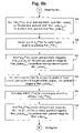
- FIG. 3 is a flow chart diagram of a method for generating a monochrome dither matrix in accordance with an embodiment of the present invention
- FIG. 4 is a graph depicting the impulse response of a parametric linear filter generated in accordance with an embodiment of the present invention, at each of two different gray levels;
- FIG. 5 is a graph illustrating exemplary spot profile functions that can be used in generating a parametric linear filter that can be used to generate a joint CM dither matrix in accordance with an embodiment of the present invention.
- FIGS. 6 a - 6 c are flow chart diagrams of a method for generating a joint CM dither matrix in accordance with an embodiment of the present invention.
- FIG. 7 illustrates results for different gray levels G and dot sizes.
- the present invention encompasses a method and system for forming an image.
- the method can be implemented in software, firmware, and/or hardware, as illustrated in FIG. 1 .
- the method can be implemented in software (executable code) that is installed or instantiated on the processor of a host computer and/or the processor of an image forming device.
- the method can be implemented in a dedicated or specially-programmed logic device, such as an ASIC (Application Specific Integrated Circuit) or microcontroller.
- ASIC Application Specific Integrated Circuit
- the present invention is described in the context of a laser printer or laser printing system. However, it should be clearly understood that the present invention is not limited to this particular context or application, but rather, is broadly applicable to any image forming device or printing system application.
- FIG. 1 there can be seen a high-level functional block diagram of a system 22 according to the present invention, which can be used in an image forming or printing application.
- the system 22 includes a processor 23 and a memory 24 , with the processor 22 being programmed to implement a method of the present invention.
- an exemplary embodiment of the method implemented by the system 22 assumes that the gray scale image consists of pixels each having a gray level of between 0 (white) and 255 (black). However, it should be understood that the present invention is not limited to any particular gray level range. Further, in the following description, it is assumed that an ascending gray level numbering convention is used. However, it will be readily apparent to those having ordinary skill in the pertinent art that the present invention can be practiced using the inverse of the described logic, in the event that a descending gray level numbering convention is used instead.
- the term “minority pixel” refers to a dot for all gray levels G i ⁇ 0.5 G max
- the term “majority pixel” refers to a dot for all gray levels G i >0.5 G max
- the term “minority pixel” refers to a “no dot” for all gray levels G i ⁇ 0.5 G max
- the term “majority pixel” refers to a “no dot” for all gray levels G i >0.5 G max .
- the term “dither halftone pattern” refers to the pattern of “dots” and “no dots” (i.e., 1s and 0s) generated for each gray level.
- the term “dither array” refers to the array of gray scale values generated for each gray level.
- the term “dither matrix” refers to the combination or composite of the dither arrays for each respective gray level G i . The dither matrix is used in generating the output halftone image.
- a parametric filter is generated for each gray level above a transition gray level G t , based upon the desired spot profile function or spatial halftone statistics for each respective gray level of the output halftone image to be produced.
- Suitable techniques for deriving and mathematically describing optimum halftone statistics for different applications and environments are disclosed in an article entitled “Digital color halftoning with generalized error diffusion and multichannel green-noise masks”, by D. Lau, G. Arce and N. Gallagher, published in IEEE Transactions on Image Processing , Vol. 9, pp 923-935, May 2000.
- the present invention is not limited to any particular halftone statistics or spot profile function.
- a dither halftone pattern for the transition gray level G t is first generated in any suitable manner, e.g., using any suitable filter, such as a Gaussian low-pass filter, or alternatively, using any other FM screen design method, such as the method described in an article entitled “FM screen design using the DBS algorithm”, by J. Allebach and Q. Lin, published in Proc. IEEE International Conf. on Image Processing , Vol. I , pp. 549-552, September 1996.
- any suitable filter such as a Gaussian low-pass filter
- any other FM screen design method such as the method described in an article entitled “FM screen design using the DBS algorithm”, by J. Allebach and Q. Lin, published in Proc. IEEE International Conf. on Image Processing , Vol. I , pp. 549-552, September 1996.
- a dither halftone pattern for each respective gray level below (“lighter than”) the transition gray level G t is generated in any suitable manner, e.g., using any suitable filter, such as a Gaussian low-pass filter, or alternatively, using any other FM screen design method, such as described in the article entitled “FM screen design using the DBS algorithm”, by J. Allebach and Q. Lin, published in Proc. IEEE International Conf. on Image Processing , Vol. I, pp. 549-552, September 1996.
- step 102 a parametric filter for each gray level above (“darker than”) the transition gray level G t is generated, based upon a desired spot profile function or spatial halftone statistics.
- a parametric filter is used to generate a dither halftone pattern for each respective gray level above (“darker than”) the transition gray level G t .
- a Gaussian low-pass filter can be used to generate the dither halftone pattern for each gray level until the pattern achieves a prescribed dot density, e.g., until the pattern becomes dense enough that the dots almost begin to touch, at which point a parametric filter can be used to take advantage of its superior dot growth and spatial modulation characteristics, e.g., to produce clusters of dots that can be reliably and stably produced by a given printer.
- the transition gray level G t can be selected to be the lightest gray level (e.g., 0), in which case, the parametric filter is used to generate the dither halftone pattern for all gray levels (e.g., 0-255).
- a first parametric filter that does not produce dot clustering can be used to generate the dither halftone pattern for the transition gray level G t and all lighter gray levels
- a second parametric filter that does produce dot clustering can be used to generate the dither halftone pattern for all gray levels darker than the transition gray level G t .
- the particular methodology used in generating the dither halftone pattern for the transition gray level G t and all lighter gray levels is not limiting to the present invention, in its broadest sense.
- the order in which the dither halftone patterns are generated is not limiting to the present invention, in its broadest sense.
- the dither halftone pattern for the transition gray level G t be generated first, alternatively, the dither halftone pattern for the lightest gray level can be generated first, with the dither halftone patterns for successively darker gray levels being generated thereafter.
- the parametric filter has the general characteristics of a donut filter, i.e., peaks occurring away from the current pixel, in order to cause a stochastic clustering of dots in the dither halftone pattern for each respective gray level within the prescribed gray level range.
- a donut filter i.e., peaks occurring away from the current pixel
- stochastic clustered-dot halftone patterns are moiré and pattern free, and are also less likely to show bands.
- stochastic clustered-dot halftone patterns exhibit halftone noise very similar to that of the grain noise of a real photograph, superior tone reproduction characteristics, and more stable dots in printing engines with dot-to-dot interaction.
- a Gaussian filter has a local maxima at its center
- the parametric filter has a local maxima at a location other than its center, and can have a local minima at its center, although these features are not limiting to the present invention, in its broadest aspects.
- FIG. 2 there can be seen a graph illustrating an exemplary spot profile function f Gi (x) that defines desired spatial halftone statistics of a corresponding gray level G i of the output halftone image to be produced using the method of the present invention.
- the exemplary spot profile function f Gi (x) shown in FIG. 2 represents a desired radial distribution of minority pixels in the corresponding gray level G i of the output halftone image, where x is expressed in units of average distance between minority pixels X.
- the exemplary spot profile function f Gi (x) shown in FIG. 2 thus defines the desired shape, size, and distribution of dot clusters, or “spots,” in the output halftone image, at gray level G i .
- spot profile function f Gi (x) shown in FIG. 2 thus defines the desired shape, size, and distribution of dot clusters, or “spots,” in the output halftone image, at gray level G i .
- spot profile function f Gi (x) shown in FIG. 2 thus defines the desired shape, size, and distribution of dot clusters, or “spots,” in the output halftone image, at gray level G i .
- spot profile function f Gi (x) shown in FIG. 2 thus defines the desired shape, size, and distribution of dot clusters, or “spots,” in the output halftone image, at gray level G i .
- spot profile function f Gi (x) shown in FIG. 2 can be used instead of the exemplary spot profile function f Gi (x) shown in FIG. 2 .
- a dither halftone pattern is generated for the transition gray level G t , and for each gray level lighter than the transition gray level G t , in any convenient manner.
- gray level range is 0 to 255
- gray level 25 can be set to be the transition gray level G t .
- the transition gray level G t can be set to be the lightest gray level, e.g., 0.
- the value of ⁇ can be selected to shape the impulse response of the parametric linear filter F Gi (x) as desired.
- the dither halftone pattern for all gray levels G i ⁇ G t are generated, in any suitable manner.
- the parametric linear filter F Gi (x) generated in accordance with equation (1) can be used to generate the dither halftone pattern for all gray levels G i ⁇ G t , and for all gray levels G i >G t , with the spot profile function f Gi (x) for all gray levels G i ⁇ G t being designed to exhibit no dot clustering, and the spot profile function f Gi (x) for all gray levels G i >G t being designed to exhibit dot clustering.
- the parametric linear filter used in generating the dither halftone pattern for all gray levels G i ⁇ G t can be considered a first type of parametric linear filter
- the parametric linear filter used in generating the dither halftone pattern for all gray levels G i >G t can be considered a second type of parametric linear filter.
- step 302 the dither halftone pattern for the previous (“nearest lighter”) gray level G i ⁇ 1 is filtered using the parametric linear filter F Gi (x) for gray level G i >G t , to produce (filter_output [i][j]). If the size of the dither matrix is less than the size of the original or source gray scale image to be halftoned, then the filtering is carried out using circular convolution.
- step 303 for all gray levels G i ⁇ 0.5 G max , a search is performed to find the majority pixel where the (filter_output [i][j]) (or the (updated filter_output n ) obtained during the previous iteration of step 306 ) is minimum; for all gray levels G i >0.5 G max , a search is performed to find the minority pixel where the (filter_output [i][j]) (or the (updated filter_output n ) obtained during the previous iteration of step 306 ) is maximum.
- the minority pixels are dots, and for all gray levels>0.5 G max , the majority pixels are dots.
- the identified majority pixel is converted to a minority pixel.
- the identified minority pixel is converted to a majority pixel. In each case, the result of the “conversion” process is the addition of a “dot.”
- step 304 a decision is made as to whether the appropriate concentration of minority pixels (i.e., the appropriate ratio of minority pixels/total pixels) has been achieved by virtue of the last conversion of a majority pixel to a minority pixel, or vice versa, in step 303 .
- the appropriate ratio of minority pixels/total pixels for a each gray level G i ⁇ 0.5 G max is G i /G max
- the appropriate ratio of minority pixels/total pixels for each gray level G i >0.5 G max is 1 ⁇ (G i /G max ).
- the appropriate ratio of minority pixels/total pixels for gray level 0.1 G max is 0.1
- step 304 If the decision made in step 304 is “no,” then processing proceeds to step 305 .
- step 305 the parametric linear filter F Gi (x) for the current gray level G i is shifted, to produce a circularly shifted version Fsh Gi [i,j] n of the parametric linear filter F Gi (x), where Fsh Gi [i,j] is computed in accordance with the following equation (4):
- Fsh Gi [i,j] n F Gi [mod(( x 0 ⁇ i ), Xsize )][mod(( y 0) ⁇ j ), Ysize )], (4)
- mod represents the positive integer modulo operation;
- x0, y0 represents the position of the last-added dot,
- Fsh Gi [i,j] represents F Gi (x) in rectangular coordinates, and
- n represents the current iteration of steps 303 - 306 for generating a dither halftone pattern for a given gray level G i .
- step 306 the circularly shifted version Fsh Gi [i,j] n of the parametric linear filter F Gi (x) obtained in step 305 is added to (or subtracted from) (filter_output [i][j]) or the previous updated filter output (updated filter_output n ⁇ 1 ), to thereby obtain a new updated filter output (updated filter_output n ), where n represents the current iteration of steps 303 - 306 for generating a dither halftone pattern for a given gray level G i .
- Steps 303 - 306 are repeated for the current gray level G i until the dither halftone pattern for the current gray level G i is completed, i.e., until the decision at step 304 is “yes.”
- steps 302 - 306 are repeated for the next higher gray level G i+1 , and thereafter, for each successively higher gray level, until a dither halftone pattern has been generated for all gray levels.
- a dither halftone pattern is generated for each gray level G i >G t by replacing zeroes (“0s”) in the dither halftone pattern for the next lower (lighter) gray level with ones (“1s”), in essence, “adding dots” to the dither halftone pattern for the next lower gray level, using a parametric linear filter that produces dot clustering.
- a dither halftone pattern is generated for each gray level G i by using the existing “1s” or “dots” of the dither halftone pattern for the next lighter gray level G i ⁇ 1 as seeds where clustered dots are grown.
- the dither halftone patterns corresponding to successively darker gray levels can be viewed as successively darker, clustered-dot halftone patterns.
- a dither array is generated for each gray level G i by assigning a gray scale value to each element of the dither halftone pattern that was generated for that respective gray level G i . More particularly, for a given gray level G i , each dot (“1”) in the dither halftone pattern for that given gray level G i that was added during the generation of the dither halftone pattern for that given gray level G i , is assigned the value i. For example, the elements of the dither array for gray level 187 corresponding to each dot that was added during the generation of the dither halftone pattern for gray level 187 will be assigned a value of 187.
- step 308 the dither matrix to be used in producing the output halftone image is generated by superimposing or combining all of the dither arrays for each of the gray levels G i .
- the resultant dither matrix can be considered a composite of the dither arrays for each respective gray level G i .
- step 310 based upon the comparison made in step 309 , a determination is made as to whether or not a dot should be formed in the corresponding pixel location of the output halftone image.
- a dot is formed in a pixel location of the output halftone image if the gray scale value of the corresponding pixel of the original gray scale image is ⁇ the gray scale value of the corresponding element of the dither matrix; otherwise, no dot is formed at that pixel location in the output halftone image.
- Steps 309 and 310 are repeated until the output halftone image is completely formed.
- the present invention can also be used to jointly design any number of colorant dither matrices for transforming a color image to a color halftone image, by generating a matrix-valued parametric linear filter (or, equivalently, a set of parametric linear filters), and then using that filter (set of filters) to generate a colorant dither matrix for any two or more colorants of the color halftone image, incorporating any desired constraints that apply to color image processing, e.g., a constraint that minimizes or prohibits the superposition of both cyan and magenta in the same pixel location of the output color halftone image.
- a matrix-valued filter or set of filters
- an individual parametric filter could instead be used to separately design independent colorant dither matrices.
- FIG. 5 there can be seen a graph illustrating an exemplary colorant spot profile function f Gi CC (x) that defines desired spatial halftone statistics of the cyan colorant of a corresponding gray level G i of the output color halftone image, without respect to any other colorant; and, an exemplary colorant spot profile function f Gi CM (x) that defines desired spatial halftone statistics of the magenta colorant of a corresponding gray level G i of the output color halftone image, with respect to the cyan colorant.
- the exemplary colorant spot profile functions f Gi CM (x) and f Gi CC (x) shown in FIG. 5 thus define the desired shape, size, and distribution of dot clusters, or “spots,” of the cyan colorant, and of the magenta colorant with respect to the cyan colorant, respectively, in the output color halftone image, at gray level G i .
- Colorant spot profile functions f Gi MM (x) and f Gi MC (x) are used to define desired spatial halftone statistics of the magenta colorant of a corresponding gray level G i of the output color halftone image, without respect to any other colorant, and of the cyan colorant with respect to the magenta colorant, respectively.
- the colorant spot profile functions f Gi CC (x) and f Gi MM (x), and the colorant spot profile functions f Gi CM (x) and f Gi MC (x) are assumed to be the same, for sake of convenience and simplicity, except that the origin point for the colorant spot profile functions f Gi MM (x) and f Gi MC (x) is a magenta minority pixel, rather than a cyan minority pixel.
- the colorant spot profile functions f Gi MC (x) and f Gi MM (x) are not separately depicted in the drawings.
- the present invention is not limited to this embodiment.
- the colorant spot profile functions f Gi CC (x) and f Gi MM (x), and the colorant spot profile functions f Gi CM (x) and f Gi MC (x) can be different, e.g., if an assymetrical distribution of cyan and magenta colorants is desired.
- colorant dither matrices for only two colorants (cyan (C) and magenta (M)) used in forming the output color halftone image
- C cyan
- M magenta
- the present invention can be used to generate colorant dither matrices for any one or more colorants, in any desired color space (e.g., CMYK or RGB).
- the cyan and magenta colorant dither matrices generated using the method of the exemplary embodiment can alternatively be considered to constitute a joint C, M colorant dither matrix with each element thereof having a vector value [k, l], where k represents the cyan (C) value and l representes the magenta (M) value for a given element, and where k and l can be either “0” or “1.”
- a dither colorant halftone pattern for the transition gray level G t is first generated in any suitable manner, e.g., in the manner described in “Color FM screen design using the DBS algorithm”, Color Imaging: Device-Iindependent Color, by Q. Lin and J. Allebach, published in Color Hardcopy, and Graphic Arts - III , Vol. 3300, pp 353-361, 1998; or alternatively, using any other convenient colorant halftone screen design method.
- a dither colorant halftone pattern for each respective gray level below (“lighter than”) the transition gray level G t is generated in any suitable manner, e.g., in the manner described in “Color FM screen design using the DBS algorithm”, Color Imaging: Device-Iindependent Color, by Q. Lin and J. Allebach, published in Color Hardcopy , and Graphic Arts - III , Vol. 3300, pp 353-361, 1998; or alternatively, using any other suitable colorant halftone screen design method.
- a set of parametric filters are used to generate the cyan and magenta dither colorant halftone patterns for each respective gray level above (“darker than”) the transition gray level G t .
- the transition gray level G t can be selected to be the lightest gray level (e.g., 0), in which case, the set of parametric filters are used to generate the cyan and magenta dither colorant halftone patterns for all gray levels (e.g., 0-255).
- a first type of matrix-valued parametric filter (or set of parametric filters) that does not produce dot clustering can be used to generate the cyan and magenta dither colorant halftone patterns for the transition gray level G t and all lighter gray levels
- a second type of matrix-valued parametric filter (or set of parametric filters) that does produce dot clustering can be used to generate the cyan and magenta dither colorant halftone patterns for all gray levels darker than the transition gray level G t .
- the particular methodology used in generating the dither colorant halftone patterns for the transition gray level G t and all lighter gray levels is not limiting to the present invention, in its broadest sense.
- the order in which the dither colorant halftone patterns are generated is not limiting to the present invention, in its broadest sense.
- the dither colorant halftone pattern for the transition gray level G t be generated first, alternatively, the dither colorant halftone pattern for the lightest gray level can be generated first, with the dither colorant halftone patterns for successively darker gray levels being generated thereafter.
- FIGS. 6 a - 6 c there can be seen a flow chart diagram of a method for jointly designing and generating cyan and magenta color dither matrices, in accordance with an exemplary embodiment of the present invention.
- a parametric linear filter F Gi CC (x) is generated, for each gray level G i >G t , in accordance with the following equation (7):
- F Gi CC ( x ) (1 ⁇ )*(log f Gi CC ( x )/log f Gi CC (0))+ ⁇ e ⁇ x 2 , (7)
- ⁇ [0,1] ⁇ is a parameter that represents a trade-off between uniform dot growth and optimum halftone statistics as defined by the colorant spot profile function f Gi CC (x), and x is expressed in units of average inter-minority colorant pixel distance X.
- the value of ⁇ can be selected to shape the impulse response of the parametric linear filter F Gi CC (x) as desired.
- a parametric linear filter F Gi MM (x) is generated, for each gray level G i >G t , in accordance with the following equation (8):
- F Gi MM ( x ) (1 ⁇ )*(log f Gi MM ( x )/log f Gi MM (0))+ ⁇ e ⁇ x 2 , (8) where ⁇ [0,1], ⁇ is a parameter that represents a trade-off between uniform dot growth and optimum halftone statistics as defined by the colorant spot profile function f Gi MM (x), and x represents units of average inter-minority colorant pixel distance X.
- the value of ⁇ can be selected to shape the impulse response of the parametric linear filter F Gi MM (x) as desired.
- gray level 25 can be set to be the transition gray level G t .
- the transition gray level G t can be set to be the lightest gray level, e.g., 0.
- Cyan and magenta colorant halftone patterns are generated in steps 702 - 713 , as described below, for each gray level G i >G t .
- step 702 the cyan dither colorant halftone pattern for the previous (“nearest ligher”) gray level G i ⁇ 1 is filtered using the parametric linear filter F Gi CC (x) , to thereby produce a filter_output cc .
- the magenta dither colorant halftone pattern for the previous (“nearest ligher”) gray level G i ⁇ 1 is filtered using the parametric linear filter F Gi CM (x), to thereby produce a filter_output cm .
- the filter_Output cc and the filter_output cm are added together, to thereby produce the cyan filter_output c .
- magenta dither colorant halftone pattern for the previous (“nearest ligher”) gray level G i ⁇ 1 is filtered using the parametric linear filter F Gi MM (x), to thereby produce a filter_output mm .
- the magenta dither colorant halftone pattern for the previous (“nearest ligher”) gray level G i ⁇ 1 is filtered using the parametric linear filter F Gi MC (x), to thereby produce a filter_output mc .
- the filter_output mm and the filter_output mc are added together, to thereby produce the magenta filter_output m . If the size of the dither matrix is less than the size of the original or source color image to be halftoned, then the filtering is carried out using circular convolution.
- step 703 for all gray levels G i ⁇ 0.5 G max , a search is performed to find the majority cyan pixel where the cyan filter output c (or the updated cyan filter_output cn obtained during the previous iteration of step 705 ) is minimum; for all gray levels G i >0.5 G max , a search is performed to find the minority cyan pixel where the cyan filter_output c (or the updated cyan filter_output cn obtained during the previous iteration of step 705 ) is maximum. For all gray levels G i ⁇ 0.5 G max , the minority pixels are dots, and for all gray levels>0.5 G max , the majority pixels are dots.
- the identified majority pixel is converted to a minority pixel.
- the identified minority pixel is converted to a majority pixel. In each case, the result of the “conversion” process is the addition of a “dot.”
- step 704 the parametric linear filter F Gi CC (x) for the current gray level G i is circularly shifted, to thereby produce a circularly shifted version Fsh Gi CC (x) n of the parametric linear filter F Gi CC (x) for the current gray level G i , where n represents the current iteration of steps 703 - 712 for the current gray level G i .
- step 705 the circularly shifted version Fsh Gi CC (x) n of the parametric linear filter F Gi CC (x) obtained in step 704 is added to (or subtracted from) the cyan filter_output c (or the updated cyan filter_output cn ⁇ 1 obtained during the previous iteration of step 705 ), to thereby obtain a new updated cyan filter_output cn .
- step 706 the parametric linear filter F Gi MC (x) for the current gray level G i is circularly shifted, to thereby produce a circularly shifted version Fsh Gi MC (x) n of the parametric linear filter F Gi MC (x) for the current gray level G i .
- step 707 circularly shifted version Fsh Gi MC (x) n of the parametric linear filter F Gi MC (x) obtained in step 706 is added to (or subtracted from) the magenta filter_output m (or the updated magenta filter_output mn ⁇ 1 obtained during the previous iteration of step 710 ), to thereby obtain a new updated magenta filter_output mn .
- step 708 for all gray levels G i ⁇ 0.5 G max , a search is performed to find the majority magenta pixel output m (or the updated magenta filter_output mn obtained during the previous iteration of step 710 ) is minimum; for all gray levels G i >0.5 G max , a search is performed to find the minority magenta pixel where the magenta filter_output m (or the updated magenta filter_output mn obtained during the previous iteration of step 710 ) is maximum.
- step 709 the parametric linear filter F Gi MM (x) for the current gray level G i is circularly shifted, to thereby produce a circularly shifted version Fsh Gi MM (x) n of the parametric linear filter F Gi MM (x) for the current gray level G i .
- step 710 the circularly shifted version Fsh Gi MM (x) n of the parametric linear filter F Gi MM (x) obtained in step 709 is added to (or subtracted from) the magenta filter output m (or the updated magenta filter_output mn ⁇ 1 obtained during the previous iteration of step 710 ), to thereby obtain a new updated magenta filter_output mn .
- step 711 the parametric linear filter F Gi CM (x) for the current gray level G i is circularly shifted, to thereby produce a circularly shifted version Fsh Gi CM (x) n of the parametric linear filter F Gi CM (x) for the current gray level G i .
- step 712 circularly shifted version Fsh Gi CM (x) n of the parametric linear filter F Gi CM (x) obtained in step 706 is added to (or subtracted from) the cyan filter_output cd (or the updated cyan filter_output cn ⁇ 1 obtained during the previous iteration of step 705 ), to thereby obtain a new updated cyan filter_output cn .
- Steps 703 - 712 are repeated for the current gray level G i , until the cyan and magenta dither colorant halftone patterns for the current gray level G i are completed.
- Steps 702 - 712 are then repeated for the next higher gray level G i+1 , and thereafter, for each successively higher gray level, until cyan and magenta dither colorant halftone patterns have been generated for all gray levels.
- cyan and magenta dither colorant halftone patterns are generated for each gray level G i >G t by replacing zeroes (“0s”) in the dither colorant halftone pattern for the next lower (lighter) gray level with ones (“1s”), in essence, “adding dots” to the dither colorant halftone pattern for the next lower gray level.
- a dither colorant halftone pattern for both the cyan and magenta colorants is generated for each gray level G i by using the existing “1s” or “dots” of the dither colorant halftone pattern for the cyan and magenta colorants, for the next lighter gray level G i ⁇ 1 , as seeds where clustered dots are grown.
- the dither colorant halftone patterns corresponding to successively darker gray levels can be viewed as successively darker, clustered-dot colorant halftone patterns.
- a cyan dither array is generated for each gray level G i by assigning a gray scale value to each element of the cyan dither colorant halftone pattern that was generated for that respective gray level G i . More particularly, for a given gray level G i , each dot (“1”) in the cyan dither colorant halftone pattern, that was added during the generation of the cyan dither colorant halftone pattern for that given gray level G i , is assigned the value i. For example, the values of the elements of the cyan dither array for gray level 187 corresponding to each cyan dot that was added during the generation of the cyan dither colorant halftone pattern for gray level 187 will be assigned a value of 187.
- a magenta dither array is generated for each gray level G i by assigning a gray scale value to each element of the magenta dither colorant halftone pattern that was generated for that respective gray level G i . More particularly, for a given gray level G i , each dot (“1”) in the magenta dither colorant halftone pattern, that was added during the generation of the magenta dither colorant halftone pattern for that given gray level G i , is assigned the value i.
- the values of the elements of the magenta dither array for gray level 233 corresponding to each magenta dot that was added during the generation of the magenta dither colorant halftone pattern for gray level 233 will be assigned a value of 233.
- the cyan dither matrix to be used in producing the output color halftone image is generated by superimposing or combining all of the cyan dither arrays for each of the gray levels G i .
- the resultant cyan dither matrix can be considered a composite of the cyan dither arrays for each respective gray level G i .
- the magenta dither matrix to be used in producing the output color halftone image is generated by superimposing or combining all of the magenta dither arrays for each of the gray levels G i .
- the resultant magenta dither matrix can be considered a composite of the magenta dither arrays for each respective gray level G i .
- the cyan and magenta matrices can together be considered to constitute a “joint C, M dither matrix” comprised of elements each having a vector value [k, l], where k represents the cyan (C)value and l representes the magenta (M) value for a given element, and where k and l can be either “0” or “1.”
- step 716 based upon the comparison made in step 715 , a determination is made as to whether or not a cyan dot should be formed in the corresponding cyan pixel location of the output color halftone image, and a determination is made as to whether or not a magenta dot should be formed in the corresponding magenta pixel location of the output color halftone image.
- a cyan (or magenta) dot is formed in a corresponding cyan (or magenta) pixel location of the output color halftone image if the cyan (or magenta) value of the corresponding pixel of the original color image is ⁇ the gray scale value of the corresponding element of the dither matrix; otherwise, no cyan (or magenta) dot is formed at that cyan (or magenta) pixel location in the output color halftone image.
- Steps 715 and 716 are repeated until the output color halftone image is completely formed.
Abstract
Description
F Gi(x)=(1−α)*(log f Gi(x)/log f Gi(0))+αe −x
where αε[0,1], α is a parameter that represents a trade-off between uniform dot growth and optimum halftone statistics as defined by the spot profile function fGi(x), and x represents units of average inter-minority pixel distance. The value of α can be selected to shape the impulse response of the parametric linear filter FGi(x) as desired.
f Gi(x)=δ, when x≦0.5, and
f Gi(x)=G[1+δ−2(e (−10(x−0.5)
f Gi(x)=G[1+δ−2(e (−10(x−0.5)
Fsh Gi [i,j] n =F Gi[mod((x0−i), Xsize)][mod((y0)−j), Ysize)], (4)
where mod represents the positive integer modulo operation; x0, y0 represents the position of the last-added dot, FshGi[i,j] represents FGi(x) in rectangular coordinates, and n represents the current iteration of steps 303-306 for generating a dither halftone pattern for a given gray level Gi.
(filter_output [i][j])+Fsh Gi [i,j] n=(updated filter_outputn), or
(updated filter_outputn−1)+Fsh Gi [i,j] n=(updated filter_outputn). (5)
(filter_output [i][j])−Fsh Gi [i,j] n=(updated filter_outputn), or
(updated filter_outputn−1)−Fsh Gi [i,j] n=(updated filter_outputn). (6)
F Gi CC(x)=(1−α)*(log f Gi CC(x)/log f Gi CC(0))+αe −x
where αε[0,1], α is a parameter that represents a trade-off between uniform dot growth and optimum halftone statistics as defined by the colorant spot profile function fGi CC(x), and x is expressed in units of average inter-minority colorant pixel distance X. The value of α can be selected to shape the impulse response of the parametric linear filter FGi CC(x) as desired.
F Gi MM(x)=(1−α)*(log f Gi MM(x)/log f Gi MM(0))+αe −x
where αε[0,1], α is a parameter that represents a trade-off between uniform dot growth and optimum halftone statistics as defined by the colorant spot profile function fGi MM(x), and x represents units of average inter-minority colorant pixel distance X. The value of α can be selected to shape the impulse response of the parametric linear filter FGi MM(x) as desired.
F Gi CM(x)=(log f Gi CM(x)/log f Gi CM(x max))×β, (9)
where xmax represents the value of x at which CM is maximum, where β is a weighting factor that weights the joint statistics of cyan and magenta relative to the statistics of cyan alone, and where 0≦β≦1.
F Gi MC(x)=(log f Gi MC(x)/log f Gi MC(x max)), (10)
where xmax represents the value of x at which MC is maximum.
IFFT(FFT(F(x))FFT(G(x))), (11)
where IFFT denotes the inverse FFT.
Claims (38)
Priority Applications (2)
| Application Number | Priority Date | Filing Date | Title |
|---|---|---|---|
| US10/427,766 US7420709B2 (en) | 2003-04-30 | 2003-04-30 | Dither matrix generation |
| PCT/US2004/013207 WO2004100530A1 (en) | 2003-04-30 | 2004-04-30 | Dither matrix generation |
Applications Claiming Priority (1)
| Application Number | Priority Date | Filing Date | Title |
|---|---|---|---|
| US10/427,766 US7420709B2 (en) | 2003-04-30 | 2003-04-30 | Dither matrix generation |
Publications (2)
| Publication Number | Publication Date |
|---|---|
| US20040218222A1 US20040218222A1 (en) | 2004-11-04 |
| US7420709B2 true US7420709B2 (en) | 2008-09-02 |
Family
ID=33310246
Family Applications (1)
| Application Number | Title | Priority Date | Filing Date |
|---|---|---|---|
| US10/427,766 Expired - Fee Related US7420709B2 (en) | 2003-04-30 | 2003-04-30 | Dither matrix generation |
Country Status (2)
| Country | Link |
|---|---|
| US (1) | US7420709B2 (en) |
| WO (1) | WO2004100530A1 (en) |
Cited By (2)
| Publication number | Priority date | Publication date | Assignee | Title |
|---|---|---|---|---|
| US20160241828A1 (en) * | 2013-10-10 | 2016-08-18 | Dolby Laboratories Licensing Corporation | Displaying dci and other content on an enhanced dynamic range projector |
| US20220368812A1 (en) * | 2019-11-18 | 2022-11-17 | Hewlett-Packard Development Company, L.P. | Generating print agent element sets |
Families Citing this family (9)
| Publication number | Priority date | Publication date | Assignee | Title |
|---|---|---|---|---|
| EP1387340A1 (en) * | 2002-07-30 | 2004-02-04 | Deutsche Thomson-Brandt Gmbh | Method and device for processing video data for a display |
| KR100561372B1 (en) * | 2004-09-10 | 2006-03-17 | 삼성전자주식회사 | The method of designing clustered-dot screen based on the human visual characteristics and the printer model, the device thereof and the image forming device outputing binary image using the designed screen |
| US9167130B2 (en) * | 2004-11-12 | 2015-10-20 | Hewlett-Packard Development Company, L.P. | AM-FM halftone screen design |
| EP1691539A1 (en) * | 2005-02-15 | 2006-08-16 | European Central Bank | Two-dimensional security pattern that can be authenticated with one-dimensional signal processing |
| US7515303B2 (en) | 2005-03-29 | 2009-04-07 | Heidelberger Druckmaschinen Ag | Process for the modeling of dots for a screen |
| CN100377567C (en) * | 2005-10-26 | 2008-03-26 | 北京北大方正电子有限公司 | FM and AM mixed net point net shape controlling method in multi-position imaging depth device |
| US7830569B2 (en) * | 2006-03-31 | 2010-11-09 | Eastman Kodak Company | Multilevel halftone screen and sets thereof |
| EP2773508A4 (en) * | 2011-10-31 | 2015-01-07 | Hewlett Packard Development Co | Method and system for halftone printing |
| US10965836B2 (en) | 2018-07-17 | 2021-03-30 | Canon Kabushiki Kaisha | Image processing apparatus, control method thereof, and non-transitory computer-readable storage medium that execute a density unevenness correction process in accordance with properties of recording elements |
Citations (9)
| Publication number | Priority date | Publication date | Assignee | Title |
|---|---|---|---|---|
| US5555102A (en) | 1995-01-30 | 1996-09-10 | Apple Computer, Inc. | System and method for generating images with improved visual quality using local correlation, ordered dither |
| EP0977424A2 (en) | 1998-07-31 | 2000-02-02 | Hewlett-Packard Company | Halftone printing using donut filters |
| US6252679B1 (en) * | 1998-11-18 | 2001-06-26 | Xerox Corporation | Composite halftone screens with stochastically distributed clusters or lines |
| EP1168820A1 (en) | 1995-04-26 | 2002-01-02 | Polaroid Corporation | Stochastic threshold array generating subsystem and error map generator and method for generating an error map for image rendering |
| US6356363B1 (en) * | 1997-09-30 | 2002-03-12 | Lexmark International, Inc. | Method for halftoning using interlocked threshold arrays or interlocked dot profiles |
| US6433891B1 (en) | 1998-12-14 | 2002-08-13 | Oak Technology, Inc. | Stochastic screening method with dot pattern regularity control and dot growth |
| US20020163528A1 (en) | 2001-02-12 | 2002-11-07 | Cooper Brian Edward | Method for halftoning using a difference weighting function |
| US6493112B1 (en) * | 1998-01-16 | 2002-12-10 | University Of Delaware | Method and apparatus for producing halftone images using green-noise masks having adjustable coarseness |
| US6747758B1 (en) * | 1999-07-28 | 2004-06-08 | Ricoh Company, Ltd. | Digital halftoning method and apparatus, and its computer readable medium |
-
2003
- 2003-04-30 US US10/427,766 patent/US7420709B2/en not_active Expired - Fee Related
-
2004
- 2004-04-30 WO PCT/US2004/013207 patent/WO2004100530A1/en active Application Filing
Patent Citations (9)
| Publication number | Priority date | Publication date | Assignee | Title |
|---|---|---|---|---|
| US5555102A (en) | 1995-01-30 | 1996-09-10 | Apple Computer, Inc. | System and method for generating images with improved visual quality using local correlation, ordered dither |
| EP1168820A1 (en) | 1995-04-26 | 2002-01-02 | Polaroid Corporation | Stochastic threshold array generating subsystem and error map generator and method for generating an error map for image rendering |
| US6356363B1 (en) * | 1997-09-30 | 2002-03-12 | Lexmark International, Inc. | Method for halftoning using interlocked threshold arrays or interlocked dot profiles |
| US6493112B1 (en) * | 1998-01-16 | 2002-12-10 | University Of Delaware | Method and apparatus for producing halftone images using green-noise masks having adjustable coarseness |
| EP0977424A2 (en) | 1998-07-31 | 2000-02-02 | Hewlett-Packard Company | Halftone printing using donut filters |
| US6252679B1 (en) * | 1998-11-18 | 2001-06-26 | Xerox Corporation | Composite halftone screens with stochastically distributed clusters or lines |
| US6433891B1 (en) | 1998-12-14 | 2002-08-13 | Oak Technology, Inc. | Stochastic screening method with dot pattern regularity control and dot growth |
| US6747758B1 (en) * | 1999-07-28 | 2004-06-08 | Ricoh Company, Ltd. | Digital halftoning method and apparatus, and its computer readable medium |
| US20020163528A1 (en) | 2001-02-12 | 2002-11-07 | Cooper Brian Edward | Method for halftoning using a difference weighting function |
Non-Patent Citations (2)
| Title |
|---|
| Lau, D.L, Arce,G. R., Gallagher, N.C., Digital color halftoning with generalized error diffusion and multichannel green-noise masks, IEEE Transactions on Image Pressing, vol. 9, No. 5, May 2000. * |
| Ulichney, Robert, Digital HalftoningThe MIT Press, Cambridge, Massachusetts, ISBN 0-262-21009-6, Fifth Printing, 1996. * |
Cited By (5)
| Publication number | Priority date | Publication date | Assignee | Title |
|---|---|---|---|---|
| US20160241828A1 (en) * | 2013-10-10 | 2016-08-18 | Dolby Laboratories Licensing Corporation | Displaying dci and other content on an enhanced dynamic range projector |
| US10368044B2 (en) * | 2013-10-10 | 2019-07-30 | Dolby Laboratories Licensing Corporation | Displaying DCI and other content on an enhanced dynamic range projector |
| US11122244B2 (en) | 2013-10-10 | 2021-09-14 | Dolby Laboratories Licensing Corporation | Displaying DCI and other content on an enhanced dynamic range projector |
| US11677917B2 (en) | 2013-10-10 | 2023-06-13 | Dolby Laboratories Licensing Corporation | Displaying DCI and other content on an enhanced dynamic range projector |
| US20220368812A1 (en) * | 2019-11-18 | 2022-11-17 | Hewlett-Packard Development Company, L.P. | Generating print agent element sets |
Also Published As
| Publication number | Publication date |
|---|---|
| WO2004100530A1 (en) | 2004-11-18 |
| US20040218222A1 (en) | 2004-11-04 |
Similar Documents
| Publication | Publication Date | Title |
|---|---|---|
| US6493112B1 (en) | Method and apparatus for producing halftone images using green-noise masks having adjustable coarseness | |
| US5477305A (en) | Method and apparatus for halftone rendering of a gray scale image using a blue noise mask | |
| US6798537B1 (en) | Digital color halftoning with generalized error diffusion vector green-noise masks | |
| EP1169850B1 (en) | Narrow band, anisotropic stochastic halftone patterns and methods of creating and using the same | |
| Lau et al. | Digital color halftoning with generalized error diffusion and multichannel green-noise masks | |
| US7369276B2 (en) | Multi-level halftoning providing improved texture uniformity | |
| EP0642259B1 (en) | Method for making a frequency-modulation halftone screen | |
| US7420709B2 (en) | Dither matrix generation | |
| JP4149269B2 (en) | Error diffusion method and system using intermediate dots | |
| US6025930A (en) | Multicell clustered mask with blue noise adjustments | |
| US6791718B1 (en) | Halftone printing with dither matrices generated by using cluster filters | |
| Lee et al. | The hybrid screen—improving the breed | |
| US20040090654A1 (en) | FM screening with sub-dot phase modulation | |
| US6515770B1 (en) | Dither mask generation with calibration-independent number of threshold levels | |
| US6697169B1 (en) | Enhanced error diffusion using a correlated chromatic noise pattern | |
| US6597813B1 (en) | Masks with modulated clustering and aperiodicity and rescaling of masks | |
| Liu et al. | New results for aperiodic, clustered-dot halftoning | |
| Lin et al. | Generating stochastic dispersed and periodic clustered textures using a composite hybrid screen | |
| Gooran | A novel hybrid amplitude modulated/frequency modulated halftoning based on multilevel halftoning | |
| US6714318B1 (en) | Dithering method and apparatus for multitone printers | |
| Jiang et al. | Novel color halftoning algorithm for ink savings | |
| Wang et al. | Properties of Jointly-Blue Noise Masks and Application on Color Halftoning | |
| Monga et al. | Color image halftoning | |
| EP1122943B1 (en) | Continuous tone reproduction using improved ink jet droplet dispersion techniques | |
| JP2004266802A (en) | Sub-dot phase modulation for computer to plate inkjet system |
Legal Events
| Date | Code | Title | Description |
|---|---|---|---|
| AS | Assignment |
Owner name: HEWLETT-PACKARD DEVELOPMENT COMPANY L.P., TEXAS Free format text: ASSIGNMENT OF ASSIGNORS INTEREST;ASSIGNOR:HEWLETT-PACKARD COMPANY;REEL/FRAME:014061/0492 Effective date: 20030926 Owner name: HEWLETT-PACKARD DEVELOPMENT COMPANY L.P.,TEXAS Free format text: ASSIGNMENT OF ASSIGNORS INTEREST;ASSIGNOR:HEWLETT-PACKARD COMPANY;REEL/FRAME:014061/0492 Effective date: 20030926 |
|
| AS | Assignment |
Owner name: HEWLETT-PACKARD DEVEOPMENT COMPANY, L.P., TEXAS Free format text: ASSIGNMENT OF ASSIGNORS INTEREST;ASSIGNOR:DAMERA-VENKATA, NIRANJAN;REEL/FRAME:014077/0562 Effective date: 20030116 |
|
| CC | Certificate of correction | ||
| FPAY | Fee payment |
Year of fee payment: 4 |
|
| REMI | Maintenance fee reminder mailed | ||
| LAPS | Lapse for failure to pay maintenance fees | ||
| STCH | Information on status: patent discontinuation |
Free format text: PATENT EXPIRED DUE TO NONPAYMENT OF MAINTENANCE FEES UNDER 37 CFR 1.362 |
|
| FP | Lapsed due to failure to pay maintenance fee |
Effective date: 20160902 |