US7420290B2 - Apparatus for correcting driving power of vehicle actuator and method thereof - Google Patents
Apparatus for correcting driving power of vehicle actuator and method thereof Download PDFInfo
- Publication number
- US7420290B2 US7420290B2 US11/012,250 US1225004A US7420290B2 US 7420290 B2 US7420290 B2 US 7420290B2 US 1225004 A US1225004 A US 1225004A US 7420290 B2 US7420290 B2 US 7420290B2
- Authority
- US
- United States
- Prior art keywords
- battery voltage
- vehicle
- voltage
- reference voltage
- actuator
- Prior art date
- Legal status (The legal status is an assumption and is not a legal conclusion. Google has not performed a legal analysis and makes no representation as to the accuracy of the status listed.)
- Active, expires
Links
Images


Classifications
-
- B—PERFORMING OPERATIONS; TRANSPORTING
- B60—VEHICLES IN GENERAL
- B60G—VEHICLE SUSPENSION ARRANGEMENTS
- B60G17/00—Resilient suspensions having means for adjusting the spring or vibration-damper characteristics, for regulating the distance between a supporting surface and a sprung part of vehicle or for locking suspension during use to meet varying vehicular or surface conditions, e.g. due to speed or load
- B60G17/015—Resilient suspensions having means for adjusting the spring or vibration-damper characteristics, for regulating the distance between a supporting surface and a sprung part of vehicle or for locking suspension during use to meet varying vehicular or surface conditions, e.g. due to speed or load the regulating means comprising electric or electronic elements
- B60G17/0152—Resilient suspensions having means for adjusting the spring or vibration-damper characteristics, for regulating the distance between a supporting surface and a sprung part of vehicle or for locking suspension during use to meet varying vehicular or surface conditions, e.g. due to speed or load the regulating means comprising electric or electronic elements characterised by the action on a particular type of suspension unit
- B60G17/0157—Resilient suspensions having means for adjusting the spring or vibration-damper characteristics, for regulating the distance between a supporting surface and a sprung part of vehicle or for locking suspension during use to meet varying vehicular or surface conditions, e.g. due to speed or load the regulating means comprising electric or electronic elements characterised by the action on a particular type of suspension unit non-fluid unit, e.g. electric motor
-
- B—PERFORMING OPERATIONS; TRANSPORTING
- B60—VEHICLES IN GENERAL
- B60G—VEHICLE SUSPENSION ARRANGEMENTS
- B60G17/00—Resilient suspensions having means for adjusting the spring or vibration-damper characteristics, for regulating the distance between a supporting surface and a sprung part of vehicle or for locking suspension during use to meet varying vehicular or surface conditions, e.g. due to speed or load
-
- B—PERFORMING OPERATIONS; TRANSPORTING
- B60—VEHICLES IN GENERAL
- B60R—VEHICLES, VEHICLE FITTINGS, OR VEHICLE PARTS, NOT OTHERWISE PROVIDED FOR
- B60R16/00—Electric or fluid circuits specially adapted for vehicles and not otherwise provided for; Arrangement of elements of electric or fluid circuits specially adapted for vehicles and not otherwise provided for
- B60R16/02—Electric or fluid circuits specially adapted for vehicles and not otherwise provided for; Arrangement of elements of electric or fluid circuits specially adapted for vehicles and not otherwise provided for electric constitutive elements
-
- B—PERFORMING OPERATIONS; TRANSPORTING
- B60—VEHICLES IN GENERAL
- B60G—VEHICLE SUSPENSION ARRANGEMENTS
- B60G2400/00—Indexing codes relating to detected, measured or calculated conditions or factors
- B60G2400/20—Speed
- B60G2400/204—Vehicle speed
-
- B—PERFORMING OPERATIONS; TRANSPORTING
- B60—VEHICLES IN GENERAL
- B60G—VEHICLE SUSPENSION ARRANGEMENTS
- B60G2400/00—Indexing codes relating to detected, measured or calculated conditions or factors
- B60G2400/40—Steering conditions
- B60G2400/41—Steering angle
- B60G2400/412—Steering angle of steering wheel or column
-
- B—PERFORMING OPERATIONS; TRANSPORTING
- B60—VEHICLES IN GENERAL
- B60G—VEHICLE SUSPENSION ARRANGEMENTS
- B60G2600/00—Indexing codes relating to particular elements, systems or processes used on suspension systems or suspension control systems
- B60G2600/18—Automatic control means
- B60G2600/182—Active control means
-
- B—PERFORMING OPERATIONS; TRANSPORTING
- B60—VEHICLES IN GENERAL
- B60G—VEHICLE SUSPENSION ARRANGEMENTS
- B60G2600/00—Indexing codes relating to particular elements, systems or processes used on suspension systems or suspension control systems
- B60G2600/73—Electrical control
-
- B—PERFORMING OPERATIONS; TRANSPORTING
- B60—VEHICLES IN GENERAL
- B60G—VEHICLE SUSPENSION ARRANGEMENTS
- B60G2600/00—Indexing codes relating to particular elements, systems or processes used on suspension systems or suspension control systems
- B60G2600/82—Indexing codes relating to particular elements, systems or processes used on suspension systems or suspension control systems duty rate function
-
- B—PERFORMING OPERATIONS; TRANSPORTING
- B60—VEHICLES IN GENERAL
- B60G—VEHICLE SUSPENSION ARRANGEMENTS
- B60G2800/00—Indexing codes relating to the type of movement or to the condition of the vehicle and to the end result to be achieved by the control action
- B60G2800/90—System Controller type
- B60G2800/91—Suspension Control
Definitions
- the present invention relates to an apparatus that corrects the driving power of an actuator in a vehicle and a method thereof whereby the power provided to the actuator, which operates an active suspension control system, is corrected.
- a suspension system supports the weight of a vehicle and absorbs and dampens out road shocks.
- the suspension system therefore, allows the vehicle to travel over rough surfaces with minimal up and down body movement. This improves the vehicle ride of the occupants and load in the vehicle and reduces dynamic stress of each portion of the vehicle body and wheel vibration, thereby increasing the driving stability.
- An Active Geometry Controlled Suspension (AGCS) system among the suspension systems adjusts the rear wheels to a toe-in setting during the turn by elongating or shortening the length of a rear control arm, thereby minimizing the vehicle roll and improving the maneuverability.
- AGCS Active Geometry Controlled Suspension
- An AGCS Electronic Control Unit pre-determines the bump of the vehicle by receiving detection values from a steering angle sensor and vehicle speed sensor to thereby obtain a steering stability against the bump on exterior wheels when the vehicle makes a turn. Then, the AGCS ECU provides battery power to an actuator of the exterior rear wheel through a switched relay to operate the actuator, thereby obtaining the steering safety by toe-in adjustment of the exterior rear wheels.
- Embodiments of the present invention are provided to operate various actuators in the vehicle at a constant speed regardless of the variation of the battery voltage, thereby stabilizing the vehicle.
- An apparatus to correct the driving power of an actuator in a vehicle includes a comparator that compares the battery voltage of the vehicle with a predetermined reference voltage.
- a controller adjusts and outputs a duty ratio of a Pulse Width Modulation (PWM) signal according to the compared result of the battery voltage and reference voltage.
- PWM Pulse Width Modulation
- a switching element is switched on and off by the PWM signal and outputs the battery voltage after a transformation.
- An actuator operates by receiving the transformed battery voltage through the switching element.
- the controller increases the duty ratio of the PWM signal if the battery voltage is less than the reference voltage as a result of the compared result to thereby prevent a slow operation speed of the actuator due to low battery voltage.
- the controller decreases the duty ratio of the PWM signal if the battery voltage is greater than the reference voltage as a result of the compared result to thereby prevent a fast operation speed of the actuator due to high battery voltage.
- a method to correct the driving power of an actuator in a vehicle includes: comparing the battery voltage of the vehicle with a predetermined reference voltage; decreasing the duty ratio of a Pulse Width Modulation (PWM) signal if the battery voltage is greater than the reference voltage, and increasing the duty ratio of the PWM signal if the battery voltage is less than the reference voltage; and transforming and providing the battery voltage to an actuator by a switching operation according to the adjusted PWM signal.
- PWM Pulse Width Modulation
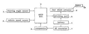
- FIG. 1 is a block diagram of an apparatus to correct an actuator driving power of a vehicle according to an embodiment of the present invention.
- FIG. 2 is a flowchart of a method to correct an actuator driving power of a vehicle according to an embodiment of the present invention.
- a steering angle sensor 1 detects a steering angle of a vehicle and inputs the result into an Active Geometry Controller Suspension Electronic Control Unit (AGCS ECU) 3 .
- a vehicle speed sensor 2 detects the speed of the vehicle to be input into the AGCS ECU 3 .
- An AD converter 7 converts the voltage of a battery 4 into a digital signal and inputs the signal into a comparator 8 .
- the comparator 8 compares the battery voltage (input from the AD converter 7 ) with a predetermined reference voltage and inputs the compared result into the AGCS ECU 3 .
- the predetermined reference voltage may be any suitable voltage and in the present embodiment is preferably 13V.
- the AGCS ECU 3 pre-determines the vehicle bump or jolt by receiving signals from the steering angle sensor 1 and vehicle speed sensor 2 and outputs a Pulse Width Modulation (PWM) signal for operating a switching element 5 , which provides the power to a rear wheel actuator 6 .
- PWM Pulse Width Modulation
- a duty ratio of the PWM signal is determined by the compared result of the battery voltage and reference voltage input from the comparator 8 .
- the AGCS ECU 3 If the battery voltage and reference voltage are identical, the AGCS ECU 3 outputs a PWM signal of a reference duty ratio (preferably 50% of the duty ratio). If the battery voltage is greater than the reference voltage, the AGCS ECU 3 decreases the duty ratio of the PWM signal from the reference duty ratio while increasing the duty ratio from the reference duty ratio if the battery voltage is less than the reference voltage. Thus, a constant operation speed of the rear wheel actuator 6 is obtained by constantly maintaining the voltage provided to the rear wheel actuator 6 .
- a reference duty ratio preferably 50% of the duty ratio
- the AGCS ECU 3 may preferably use a map table (which is preset with duty ratios according to the voltage difference) to determine the duty ratio of the PWM signal.
- the switching element 5 is switched on and off by the PWM signal (outputted from the AGCS ECU 3 ) and provides the voltage of the battery 4 to the rear wheel actuator 6 after transforming the battery voltage into a constant voltage.
- the rear wheel actuator 6 operates at a constant speed by receiving the constant battery voltage through the switching element 5 .
- the rear wheel actuator 6 preferably includes a motor 6 a that operates by receiving the power through the switching element 5 .
- the AD converter 7 detects the voltage of the battery 4 and converts the voltage into a digital signal (Step 1 ).
- the comparator 8 compares the battery voltage (converted into a digital signal) with a predetermined reference voltage (preferably 13V) (Step 2 ). If the voltage of the battery 4 exceeds the predetermined reference voltage as a result of step 2 , then the AGCS ECU 3 reduces the duty ratio of a PWM signal, which switches on or off the switching element 5 (Step 3 ). If the voltage of the battery 4 is less than the predetermined reference voltage as a result of step 2 , then the AGCS ECU 3 increases the duty ratio of the PWM signal, which switches on and off the switching element 5 (Step 4 ).
- the voltage of the battery 4 is transformed to a constant voltage and is provided to the rear wheel actuator 6 through the switching element 5 , which is switched on or off by the PWM signal, thus the rear wheel actuator 6 operates at a constant speed regardless of the voltage variation of the battery 4 (Step 5 ).
Abstract
Description
Claims (6)
Applications Claiming Priority (2)
| Application Number | Priority Date | Filing Date | Title |
|---|---|---|---|
| KR1020040073781A KR20060024917A (en) | 2004-09-15 | 2004-09-15 | Apparatus for correcting the power of a actuator in a vehicle and method therefor |
| KR10-2004-0073781 | 2004-09-15 |
Publications (2)
| Publication Number | Publication Date |
|---|---|
| US20060055242A1 US20060055242A1 (en) | 2006-03-16 |
| US7420290B2 true US7420290B2 (en) | 2008-09-02 |
Family
ID=36604767
Family Applications (1)
| Application Number | Title | Priority Date | Filing Date |
|---|---|---|---|
| US11/012,250 Active 2025-03-22 US7420290B2 (en) | 2004-09-15 | 2004-12-16 | Apparatus for correcting driving power of vehicle actuator and method thereof |
Country Status (3)
| Country | Link |
|---|---|
| US (1) | US7420290B2 (en) |
| KR (1) | KR20060024917A (en) |
| CN (1) | CN100475577C (en) |
Cited By (1)
| Publication number | Priority date | Publication date | Assignee | Title |
|---|---|---|---|---|
| US20140091741A1 (en) * | 2012-09-28 | 2014-04-03 | Samsung Electro-Mechanics Co., Ltd. | Motor driving apparatus and motor driving method |
Families Citing this family (11)
| Publication number | Priority date | Publication date | Assignee | Title |
|---|---|---|---|---|
| JP4848780B2 (en) * | 2006-01-27 | 2011-12-28 | トヨタ自動車株式会社 | Control device for cooling fan |
| ITMO20060202A1 (en) * | 2006-06-21 | 2007-12-22 | Galliano Bentivoglio | GUN TO DELIVER LIQUID FUEL |
| JP4760623B2 (en) * | 2006-09-04 | 2011-08-31 | 市光工業株式会社 | Mirror device for vehicle |
| KR20090009554A (en) * | 2007-07-20 | 2009-01-23 | 현대모비스 주식회사 | Battery equalizer for cars |
| JP4947045B2 (en) * | 2008-12-19 | 2012-06-06 | トヨタ自動車株式会社 | Cooling device and vehicle equipped with the same |
| CN102421614B (en) * | 2009-07-08 | 2014-06-11 | 丰田自动车株式会社 | Vehicular damper system |
| CN102991435B (en) * | 2011-12-31 | 2015-01-21 | 北京中科微电子技术有限公司 | Method for acquiring real-time vehicle speed of motor vehicle |
| KR102410938B1 (en) * | 2017-06-20 | 2022-06-20 | 현대자동차주식회사 | Apparatus for managing power of vehicle and method for controlling the same |
| CN108919159B (en) * | 2018-09-10 | 2021-01-29 | 长沙电咖汽车零部件制造有限公司 | Power calibration method and device |
| SE543973C2 (en) * | 2019-11-06 | 2021-10-12 | Scania Cv Ab | A battery box arrangement |
| CN110949133B (en) * | 2019-12-17 | 2021-08-13 | 东风航盛(武汉)汽车控制系统有限公司 | High-speed protection method for rotary transformer fault of electric automobile |
Citations (7)
| Publication number | Priority date | Publication date | Assignee | Title |
|---|---|---|---|---|
| US5461357A (en) * | 1992-01-29 | 1995-10-24 | Mazda Motor Corporation | Obstacle detection device for vehicle |
| US6153945A (en) * | 1997-06-30 | 2000-11-28 | Robert Bosch Gmbh | Generator regulator with overload protection means |
| US6366038B1 (en) * | 1909-11-21 | 2002-04-02 | Continental Teves Ag & Co., Ohg | Method and circuit for generating a pulse-width modulated actuating signal for a direct current actuator |
| US6426569B1 (en) * | 2000-07-13 | 2002-07-30 | Yazaki North America | Adaptive variable frequency PWM lamp-using system |
| US20040169968A1 (en) * | 2001-12-18 | 2004-09-02 | Thomas Mohr | Method and circuit arrangement for protecting an electric motor from an overload |
| US6798162B2 (en) * | 2002-07-17 | 2004-09-28 | Siemens Vdo Automotive Inc. | 12/42 volt DC brush motor control system |
| US6815898B2 (en) * | 2001-02-09 | 2004-11-09 | Robert Bosch Gmbh | Device for triggering a lighting device in a motor vehicle |
Family Cites Families (2)
| Publication number | Priority date | Publication date | Assignee | Title |
|---|---|---|---|---|
| CN1223216A (en) * | 1998-01-16 | 1999-07-21 | 金华市绿源电动车有限公司 | Method for controlling electric bicycle |
| CN1478686A (en) * | 2002-08-28 | 2004-03-03 | 朱筱杰 | Modulating type brake system |
-
2004
- 2004-09-15 KR KR1020040073781A patent/KR20060024917A/en not_active Application Discontinuation
- 2004-12-15 CN CNB200410101213XA patent/CN100475577C/en not_active Expired - Fee Related
- 2004-12-16 US US11/012,250 patent/US7420290B2/en active Active
Patent Citations (7)
| Publication number | Priority date | Publication date | Assignee | Title |
|---|---|---|---|---|
| US6366038B1 (en) * | 1909-11-21 | 2002-04-02 | Continental Teves Ag & Co., Ohg | Method and circuit for generating a pulse-width modulated actuating signal for a direct current actuator |
| US5461357A (en) * | 1992-01-29 | 1995-10-24 | Mazda Motor Corporation | Obstacle detection device for vehicle |
| US6153945A (en) * | 1997-06-30 | 2000-11-28 | Robert Bosch Gmbh | Generator regulator with overload protection means |
| US6426569B1 (en) * | 2000-07-13 | 2002-07-30 | Yazaki North America | Adaptive variable frequency PWM lamp-using system |
| US6815898B2 (en) * | 2001-02-09 | 2004-11-09 | Robert Bosch Gmbh | Device for triggering a lighting device in a motor vehicle |
| US20040169968A1 (en) * | 2001-12-18 | 2004-09-02 | Thomas Mohr | Method and circuit arrangement for protecting an electric motor from an overload |
| US6798162B2 (en) * | 2002-07-17 | 2004-09-28 | Siemens Vdo Automotive Inc. | 12/42 volt DC brush motor control system |
Cited By (1)
| Publication number | Priority date | Publication date | Assignee | Title |
|---|---|---|---|---|
| US20140091741A1 (en) * | 2012-09-28 | 2014-04-03 | Samsung Electro-Mechanics Co., Ltd. | Motor driving apparatus and motor driving method |
Also Published As
| Publication number | Publication date |
|---|---|
| US20060055242A1 (en) | 2006-03-16 |
| CN1749047A (en) | 2006-03-22 |
| CN100475577C (en) | 2009-04-08 |
| KR20060024917A (en) | 2006-03-20 |
Similar Documents
| Publication | Publication Date | Title |
|---|---|---|
| US7420290B2 (en) | Apparatus for correcting driving power of vehicle actuator and method thereof | |
| US9809076B2 (en) | Suspension control apparatus for damping oscillation of a vehicle | |
| US10106009B2 (en) | Suspension control apparatus for vehicle and control apparatus for damping-force adjustable shock absorber | |
| EP1623856B1 (en) | Suspension control system | |
| US20100211261A1 (en) | Vehicle behavior control system | |
| US20080290624A1 (en) | Suspension apparatus | |
| US8209067B2 (en) | Height control device for vehicle | |
| JP2007203933A (en) | Suspension device | |
| JP2002331817A (en) | Control of electrically adjustable semi-active damper | |
| CN102905916B (en) | Method for operating a motor vehicle and motor vehicle | |
| US20060138733A1 (en) | Suspension adjustment system | |
| US11376915B2 (en) | Electrically powered suspension system | |
| US8831838B2 (en) | Rear wheel toe angle control system | |
| KR20090094509A (en) | System for compensating damping force of electronic controlled adjustable damper and method thereof | |
| US9002576B2 (en) | Control device and method for operating a motor vehicle | |
| US7012513B2 (en) | Method and device for dynamic setting of a vehicle component | |
| CN116176204A (en) | Commercial vehicle electric control air suspension height control method based on self-adaptive fuzzy PID algorithm | |
| US6616150B2 (en) | Ride leveler system in vehicles | |
| US10179495B2 (en) | System and method for adjusting a motor vehicle chassis | |
| US8326495B2 (en) | Method of regulating a chassis of a motor vehicle, regulating system for a motor vehicle, and motor vehicle | |
| JP6975014B2 (en) | Body attitude control device | |
| WO2024024216A1 (en) | Shock absorber | |
| JP2011005928A (en) | Toe-angle control device for vehicle | |
| KR100592379B1 (en) | Solenoid Valve Control Device of Automobile Suspension | |
| KR100648811B1 (en) | Control method for active geometry controlled suspension system |
Legal Events
| Date | Code | Title | Description |
|---|---|---|---|
| AS | Assignment |
Owner name: HYUNDAI MOBIS CO., LTD., KOREA, REPUBLIC OF Free format text: ASSIGNMENT OF ASSIGNORS INTEREST;ASSIGNOR:LEE, BYOUNG-SANG;REEL/FRAME:016414/0370 Effective date: 20050211 |
|
| STCF | Information on status: patent grant |
Free format text: PATENTED CASE |
|
| FEPP | Fee payment procedure |
Free format text: PAYOR NUMBER ASSIGNED (ORIGINAL EVENT CODE: ASPN); ENTITY STATUS OF PATENT OWNER: LARGE ENTITY |
|
| FEPP | Fee payment procedure |
Free format text: PAYOR NUMBER ASSIGNED (ORIGINAL EVENT CODE: ASPN); ENTITY STATUS OF PATENT OWNER: LARGE ENTITY Free format text: PAYER NUMBER DE-ASSIGNED (ORIGINAL EVENT CODE: RMPN); ENTITY STATUS OF PATENT OWNER: LARGE ENTITY |
|
| FPAY | Fee payment |
Year of fee payment: 4 |
|
| FPAY | Fee payment |
Year of fee payment: 8 |
|
| MAFP | Maintenance fee payment |
Free format text: PAYMENT OF MAINTENANCE FEE, 12TH YEAR, LARGE ENTITY (ORIGINAL EVENT CODE: M1553); ENTITY STATUS OF PATENT OWNER: LARGE ENTITY Year of fee payment: 12 |