US7409255B2 - Module evaluation method and system - Google Patents
Module evaluation method and system Download PDFInfo
- Publication number
- US7409255B2 US7409255B2 US11/674,279 US67427907A US7409255B2 US 7409255 B2 US7409255 B2 US 7409255B2 US 67427907 A US67427907 A US 67427907A US 7409255 B2 US7409255 B2 US 7409255B2
- Authority
- US
- United States
- Prior art keywords
- constructed
- equipment
- module
- arrangement
- modularization
- Prior art date
- Legal status (The legal status is an assumption and is not a legal conclusion. Google has not performed a legal analysis and makes no representation as to the accuracy of the status listed.)
- Expired - Fee Related
Links
Images


Classifications
-
- G—PHYSICS
- G06—COMPUTING; CALCULATING OR COUNTING
- G06Q—INFORMATION AND COMMUNICATION TECHNOLOGY [ICT] SPECIALLY ADAPTED FOR ADMINISTRATIVE, COMMERCIAL, FINANCIAL, MANAGERIAL OR SUPERVISORY PURPOSES; SYSTEMS OR METHODS SPECIALLY ADAPTED FOR ADMINISTRATIVE, COMMERCIAL, FINANCIAL, MANAGERIAL OR SUPERVISORY PURPOSES, NOT OTHERWISE PROVIDED FOR
- G06Q10/00—Administration; Management
- G06Q10/06—Resources, workflows, human or project management; Enterprise or organisation planning; Enterprise or organisation modelling
Definitions
- the present invention relates to a module evaluation method and system for use with a modular construction method which is one of construction methods for plants, etc.
- module construction method means a method for constructing and installing plant equipment through steps of prefabricating the equipment, such as piping and devices adjacent to each other, into modules, i.e., units of assembly constructed beforehand, transporting the modules to an installation site in a plant, and installing the modules in integral structure.
- assembly work can be performed in a factory where environment is better and the work cost is lower than those in the site or field, thus resulting in a reduction of the total cost due to a reduction of the assembly and installation cost, etc.
- lump wok for installation of the individual modules can reduce the amount of required field work that is subjected to severe method restrictions, thus resulting in a cut of the construction term.
- the effect of the modular construction method depends on the arrangement of constructed equipment even in the same plant or in the same area within the plant. Namely, when the modular construction method is applied, the resulting effect is high in some area, is low in other area, and is minus in still other area. It is therefore important to select modules providing a high effect. Further, because design work required for the modular construction method is not performed when the modular construction method is not employed, such design work has to be effectively performed to minimize an additional cost.
- Patent Document 1 JP,A 10-1432366 discloses one known technique for determining effectiveness of a modularization range in a plant. This disclosed technique determines effectiveness of the modularization based on assembly workability of structural components within the range of a module.
- Patent Document 2 JP,A 2002-355724 discloses one known technique for automatically performing assembly and disassembly steps of general products. This disclosed technique determines the assembly and disassembly cost based on robot simulation of the assembly and disassembly steps of the products, and then determines the propriety of the assembly and disassembly steps depending on the amount of the cost.
- the modular construction method applied to a plant does not mean simple replacement of assembly steps and procedures, but it is featured in transporting modules, which are prefabricated in a place differing from a final installation site, to the installation site and installing the modules there.
- An object of the present invention is to realize a module evaluation method and system which can quickly determine overall effectiveness of the modular construction method in an automatic manner, taking into account the transportation cost and so on.
- constructed-equipment layout data including constructed-equipment arrangement schedule data for a region where arrangement of constructed equipment is scheduled, constructed-equipment modularization work data, and arrangement data for transportation of the modularized constructed-equipment to the arrangement scheduled region, as well as on constructed-equipment physical quantity data representing the number, sizes and weights of individual units of the constructed equipment
- calculations are made on a unit-rate reduction amount resulting from modularizing the constructed equipment, a transportation cost required for transporting the modularized constructed-equipment to the arrangement scheduled region, a temporary construction cost including a cost of reinforcing materials to reinforce the modularized constructed-equipment for transporting the modularized constructed-equipment to the arrangement scheduled region, and a field physical-quantity reduction effect cost corresponding to a reduction of physical quantity required for assembling the constructed equipment in the arrangement scheduled region, which is resulted from modularizing the constructed equipment.
- a cost required for modularizing the constructed equipment and a cost reduction resulting from modularizing the constructed equipment are calculated, and the modular
- the present invention can realize the module evaluation method and system capable of quickly determining overall effectiveness of the modular construction method in an automatic manner, taking into account the transportation cost and so on.
- FIG. 1 is a block diagram of a module evaluation system to which is applied a first embodiment of the present invention
- FIG. 2 shows one example of the data storage format of constructed-equipment arrangement data stored in a constructed-equipment layout data storage
- FIG. 3 shows one example of part shape library data
- FIG. 4 shows one example of a part library table
- FIG. 5 shows one example of a 3D-CAD representation based on the constructed equipment arrangement data
- FIG. 6 shows one example of the data storage format of constructed-equipment construction data
- FIG. 7 shows one example of the data storage format of constructed-equipment transportation arrangement data
- FIG. 8 shows one example of the data storage format of constructed-equipment physical quantity data
- FIG. 9 is a flowchart of processing executed by a module evaluation unit
- FIG. 10 shows one example of a unit rate table
- FIG. 11 shows one example of the data storage format of a transportation cost table
- FIG. 12 shows one example of the module evaluation result displayed on a display
- FIG. 13 is a flowchart of processing for determination of modularization effectiveness in a second embodiment of the present invention.
- FIG. 14 shows one example of a screen image displayed for use in setting a module frame
- FIG. 15 is a flowchart of processing for determination of modularization effectiveness in a third embodiment of the present invention.
- FIG. 16 shows one example of a user display/operating screen.
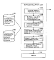
- FIG. 1 is a block diagram of a module evaluation system to which is applied a first embodiment of the present invention.
- the module evaluation system comprises a storage 101 for storing constructed-equipment layout data (including constructed-equipment arrangement schedule data for a region where arrangement of constructed equipment is scheduled, constructed-equipment modularization work data, and arrangement data for transportation of the modularized constructed-equipment to the arrangement scheduled region), a storage 102 for storing constructed-equipment physical quantity data (representing the number, sizes and weights of individual parts of the constructed equipment), a module evaluation unit 103 , and a display 104 .
- constructed-equipment layout data including constructed-equipment arrangement schedule data for a region where arrangement of constructed equipment is scheduled, constructed-equipment modularization work data, and arrangement data for transportation of the modularized constructed-equipment to the arrangement scheduled region
- a storage 102 for storing constructed-equipment physical quantity data (representing the number, sizes and weights of individual parts of the constructed equipment)
- a module evaluation unit 103 for storing constructed-equipment physical quantity data (representing the number, sizes and weights of individual parts of the constructed equipment
- the module evaluation unit 103 comprises a physical quantity data preparing section 103 A, an in-module unit-rate reduction effect determining section 103 B, a transportation cost effect determining section 103 C, a temporary construction cost effect determining section 103 D, a density reduction effect determining section 103 E, and a field physical-quantity reduction effect determining section 103 F.
- the constructed-equipment layout data storage 101 stores the constructed-equipment arrangement data that contains data representing the shapes and arrangement of the constructed equipment, the constructed-equipment construction data that contains construction information of the constructed equipment, and the constructed-equipment transportation data that contains arrangement information of the constructed equipment during module transportation.
- FIG. 2 shows one example of the data storage format of the constructed-equipment arrangement data stored in the constructed-equipment layout data storage 101 .
- each item of the constructed-equipment arrangement data is stored per minimum component element or shape element of the part.
- a column of “Constructed-Equipment Part ID” stores an identification ID per part unit of the constructed-equipment or per management unit such as a line. Because some part or some line is made up of a plurality of constructed-equipment elements, the same data may be stored in the column of “Constructed-Equipment Part ID”. In such a case, the ID number within the relevant part is stored in a column of “In-Part ID” to identify each constructed-equipment element with combination of the Constructed-Equipment Part ID and the In-Part ID.
- a part having the Constructed-Equipment Part ID of, e.g., “PFORM005” is made up of two element parts.
- the column of “In-Part ID” can be left blank.
- Part Type and Element Type store respectively a management part type as a constructed-equipment part and a part element type per constructed-equipment element.
- Columns of “Plant” and “Area” store respectively the name of a plant and the name of an area in which the constructed-equipment is finally installed.
- a column of “Module No.” stores the number of the module as an integration target.
- a column of “Temporary Construction” stores 1 as flag data.
- a column of “Shape Type” stores a shape type of the constructed-equipment part and dimensional data.
- a column of “Arrangement” stores arrangement attribute data with regard to the arranged position and dimensions of the constructed-equipment part.
- the contents of the data stored in the column of “Arrangement” differ depending on the data in the column of “Shape Type”. Also, the contents stored as shape attribute data corresponding to individual values of the shape type data and the drawing shapes of the parts corresponding to individual values of the shape attribute data are defined as part shape library data.
- FIG. 3 shows one example of the part shape library data.
- FIG. 4 shows one example of the part library table.
- the constructed-equipment arrangement data shown in FIG. 2 is prepared by a user inputting the data through, e.g., a 3D-CAD input terminal.
- FIG. 5 shows one example of a 3D-CAD representation based on the constructed-equipment arrangement data prepared with 3D-CAD.
- FIG. 6 shows one example of the data storage format of constructed-equipment construction data which contains construction information of the constructed equipment.
- a column of “Construction ID” stores an ID value for identifying construction work.
- Columns of “Target Constructed-Equipment Part ID 1” and “Target Constructed-Equipment Part ID 2” each store an ID value or a module number of the constructed-equipment part as a target of the construction work. When the module number is stored, all the parts integrated into the module belong to the work target.
- a column of “Type” stores a type of construction work.
- a column of “Execution Place” stores the name of a work place where the construction work is executed.
- the constructed-equipment construction data shown in FIG. 6 , is prepared by the user inputting the data with 3D-CAD or 2D-CAD based on projection display on a two-dimensional space.
- FIG. 7 shows one example of the data storage format of the constructed-equipment transportation arrangement data that contains arrangement state information during transportation or carrying-in of the constructed-equipment parts.
- a column of “Constructed-Equipment Part ID” stores the identification ID of the constructed-equipment part
- a column of “Arrangement” stores arrangement attribute data of the constructed-equipment part during transportation or carrying-in of the constructed-equipment part.
- the storage format of the arrangement attribute data is similar to that of the data stored in the column of “Arrangement” for the constructed-equipment arrangement data.
- the constructed-equipment transportation arrangement data is prepared by the user inputting the data with 3D-CAD.
- the constructed-equipment physical quantity data storage 102 stores the constructed-equipment physical quantity data representing physical quantity information such as the number, volume, weight and work load of the constructed equipment.
- FIG. 8 shows one example of the data storage format of the constructed-equipment physical quantity data.
- a column of “Constructed-Equipment Physical Quantity ID” stores a constructed-equipment part ID or a constructed-equipment construction ID.
- a column of “Type” stores a part type or a construction type.
- a column of “Area” stores the name of an area in which the constructed-equipment is finally installed. Further, when the constructed-equipment part is set as a part integrated into a module, a column of “Module No.” stores the number of the module as an integration target.
- a column of “Execution Place” stores the name of a place where the construction of the constructed equipment is executed.
- a column of “Temporary Construction” stores 1 as flag data.
- Columns of “Area (square measure)”, “Weight”, and “Volume” store respectively values of a flat area or length, weight, and volume of the constructed-equipment part.
- the constructed-equipment physical quantity data shown in FIG. 8 is able to contain not only data per part of the constructed equipment, but also an average or total value of the physical quantity per type of the constructed equipment, per module number, and per execution place.
- the columns of “Diameter”, “Length”, “Weight”, and “Volume” store respective average or total values.
- the column of “Constructed-Equipment Physical Quantity ID” stores an identifier indicating the average or total value and the number of data values included.
- FIG. 9 is a flowchart of processing executed by the module evaluation unit 103 .
- the constructed-equipment physical quantity data is prepared from the constructed-equipment layout data. More specifically, in step 901 , the respective data in the columns of “Constructed-Equipment Physical Quantity ID”, “Type”, “Module No.”, “Execution Place”, and “Temporary Construction” are inputted from the constructed-equipment arrangement data and the constructed-equipment construction data. Also, the unit weight or volume of the shape type corresponding to each item of the constructed-equipment arrangement data is searched from the part library table and is multiplied by the unit length or area obtained from the shape type in the constructed-equipment arrangement data, to thereby calculate the weight or volume which is inputted as the constructed-equipment physical quantity data.
- each item of effect resulting from modularization is evaluated and determined using the constructed-equipment physical quantity data.
- Step 902 determination is made on an in-module unit-rate reduction effect that is resulted from executing the construction work of the constructed equipment in the module in a factory where working efficiency is higher than the field.
- the unit rate reduction effect obtained per constructed equipment with modularization is given by (u y ⁇ u p ) and the effect index is given by multiplying the unit rate reduction effect by the physical quantity q of the constructed equipment, i.e., (u y ⁇ u p ) ⁇ q.
- the unit rate reduction effect per module is given by a value of the following formula (1), which is obtained by totalizing, for each module, respective effects of all units of the constructed equipment integrated into the module other than the temporarily constructed equipment and the constructed work thereof: ⁇ ( u y ⁇ u p ) ⁇ q (1)
- ⁇ means totalization per module.
- a unit rate table of FIG. 10 shows, by way of example, values of work unit rates in the field (installation place) and various prefabrication factories, which are stored per module type.
- a column of “Constructed-Equipment Physical Quantity Type” stores the name of data category.
- Columns of “Target Part/Work Type” and “Condition” store respectively the target constructed-equipment part or work and the classification condition thereof.
- a column of “Unit” stores the unit of the physical quantity.
- Columns of “Field”, “Prefabrication Factory A-N” store respective values of the unit rates in the field and the prefabrication factories. The values stored in the table of FIG. 10 can be edited by the user.
- the above-mentioned unit-rate reduction effect per module can be calculated by obtaining the physical quantity information of the constructed equipment in the module from the constructed-equipment physical quantity data, obtaining the unit-rate reduction effect values of the individual constructed-equipment parts from the unit rate table in accordance with the constructed equipment type and the construction place, multiplying the physical quantity values by the unit-rate reduction effect values, and totalizing the products for all the parts in the module.
- step 903 of FIG. 9 determination is made on a transportation cost effect. More specifically, outer dimensions of the module are first determined. The outer dimensions of the module are obtained from the differences between maximum and minimum coordinate values of the parts integrated into the module in the X-, Y- and Z-directions during the transportation.
- This method is performed by obtaining, for all the constructed-equipment parts corresponding to the target module number in the constructed-equipment arrangement data and the constructed-equipment transportation arrangement data, the maximum and minimum coordinate values of the individual constructed-equipment parts in the X-, Y- and Z-directions from the shape type data, and further obtaining, based on those maximum and minimum coordinate values in the X-, Y- and Z-directions, the maximum and minimum values of all the constructed-equipment parts in the module in the X-, Y- and Z-directions.
- the arrangement data in the constructed-equipment transportation arrangement data is used in order to reflect the arrangement state during the transportation.
- the transportation cost is then determined based on the outer dimensions of the module (i.e., the module size).
- a transportation cost table storing the transportation cost by the transportation means such as track, trailer, rail transport or ship depending on the module size is used for the determination.
- FIG. 11 shows one example of the data storage format of the transportation cost table.
- columns of “(X, Y)-Lengths” and “Z-Length” store respectively the maximum lengths of the outer dimensions in the (X, Y)-directions and the Z-direction.
- columns of “Fixed Transportation Cost” and “Radix-Based Transportation Cost” store respectively the fixed cost required for the transportation and the cost distributed depending on the radix.
- items are sorted in ascending order for values of the fixed transportation cost and the radix-based transportation cost.
- transportation means of the target module is determined from the transportation cost table shown in FIG. 11 , that transportation means data not only satisfying the condition that the outer module size falls within the maximum transportation size, but also being ranked first in the ascending order.
- the (X, Y)-lengths values of the (X, Y)-lengths are replaceable.
- the module transportation cost is calculated from the transportation cost data, i.e., the result of the above determination, by using a formula (2) given below: fixed transportation cost+ ⁇ radix-based transportation cost (2)
- the module occupancy ⁇ is obtained as a ratio of the area calculated from the (X, Y)-lengths of the transportation size in the transportation cost table to an area calculated from the (X,Y)-lengths of the transportation module, or a ratio of the larger value of the (X,Y)-lengths of the transportation size in the transportation cost table to the larger value of the (X, Y)-lengths of the transportation module.
- the module transportation cost effect is determined by subtracting the transportation cost in the case of no modularization from the module transportation cost calculated above.
- the transportation cost in the case of no modularization is calculated in a similar manner to that in the above module transportation cost based on the sizes in the X-, Y- and Z-directions obtained from data of the part types representing devices, which cannot be transported in flat stacking, in the constructed-equipment arrangement data.
- step 904 of FIG. 9 determination is made on a module temporary construction cost effect.
- the physical quantity of the temporarily constructed equipment parts in the target module is obtained by searching for the relevant module name and the data in the column of “Temporary Construction” from the constructed-equipment physical quantity data shown in FIG. 8 .
- the unit rate obtained by totalizing the installation cost and the material cost of the temporarily constructed equipment is stored in the unit rate table shown in FIG. 10 with “temporary construction” put in the column of “Construction”.
- the temporary construction cost is calculated by multiplying the physical quantity of the temporarily constructed equipment parts in the target module by the value of the temporarily-constructed structure installation cost in the unit rate table.
- step 906 of FIG. 9 determination is made on a density reduction effect, i.e., an improvement of installation workability which is resulted from a reduction of density in a space not occupied by the module (i.e., in a region of the constructed-equipment arrangement scheduled area except for the region where the module is to be installed) with application of the modularization.
- a density reduction effect i.e., an improvement of installation workability which is resulted from a reduction of density in a space not occupied by the module (i.e., in a region of the constructed-equipment arrangement scheduled area except for the region where the module is to be installed) with application of the modularization.
- a density reduction effect of one k among those modules is obtained from a formula (3) given below:
- V A , v A , W A , V i , v i and W i indicate respective outer dimension volumes, sums of inner constructed-equipment volumes, and sums of inner man-hours in an area and a module i.
- the sum of the constructed-equipment volumes in each of the area and the module is calculated by totalizing the volumes of the individual constructed-equipment parts in the target area or module based on the constructed-equipment arrangement data.
- the sum of inner man-hours is calculated by, for each part of the constructed equipment in the target area or module, multiplying the physical quantity values of the number of points, area (square measure) and weight by values in the unit rate table corresponding to the relevant physical quantity type and working places, and totalizing the products.
- step 907 of FIG. 9 determination is made on a field physical-quantity reduction effect that is resulted from a reduction of the physical quantity in the field and from a reduction of various overhead costs with application of the modularization.
- the overhead costs are reduced with a cut of temporary construction scaffolds, field overseers, worker offices, lodging houses, work materials, etc., the cut being resulted from a reduction of field work with application of the modularization.
- Such a reduction effect is approximately calculated based on a linear formula of (k ⁇ W M ) using man-hours required for field installation of the constructed equipment in the module.
- W M represents the man-hours required for field installation of the constructed equipment in the module, which are calculated by multiplying the in-module physical quantities stored as the constructed-equipment physical quantity data by values of the field unit rates of the constructed-equipment physical quantity types in the unit rate table, and totalizing the products.
- k represents a value of each overhead cost that is obtained, based on an approximation formula including the construction term, the field man-hours, the field physical quantity, and the peak number of workers as parameters, by determining a contribution factor of each parameter and assuming such approximation that the parameter is proportional to the field man-hours.
- the value of k can be inputted by the user.
- the module evaluation unit 103 in FIG. 1 calculates a total of the module evaluation results for all the items, which are obtained in steps 902 - 907 of FIG. 9 , and displays the calculated total as a numerical value, while the unit-rate reduction effect, the density reduction effect, and the field physical-quantity reduction effect are regarded as plus effects and the transportation cost effect and the temporary construction cost effect are minus effects. Based on the displayed numerical value, the user can objectively evaluate effectiveness of the modularization.
- FIG. 12 shows one example of the module evaluation result displayed on the display 104 .
- the merit of the modularization and the cost required for the modularization are displayed so as to indicate how much a value of the modularization effect is.
- the modularization merit includes the effect of reducing the physical quantity in the field, the density reduction effect (i.e., the effect of enlarging a region in the site other than the modules with the modularization), and the unit-rate reduction effect.
- the cost required for the modularization includes the temporary construction cost and the transportation cost.
- the value of the modularization effect is provided as a value obtained by subtracting the cost required for the modularization from the modularization cost.
- the user can determine overall effectiveness of the modular construction method in consideration of the transportation cost and so on.
- the modularization is evaluated by calculating the transportation cost required for transportation of the module and the temporary construction cost and by comparing those costs with the merit of the modularization, it is possible to realize a module evaluation method and system which can quickly determine overall effectiveness of the modular construction method in an automatic manner, taking into account the transportation cost and so on.
- the module evaluation system shown in FIG. 1 can be realized with a personal computer and, though not shown in FIG. 1 , it includes a data input device (such as a keyboard and a mouse).
- a data input device such as a keyboard and a mouse.
- the second embodiment of the present invention is intended to, when information for definition of a module is not included in the constructed-equipment layout data, make determination on effectiveness of the range of a designated imaginary module, or automatic determination on the effective range of modularization.
- the basic configuration of the module evaluation system according to the second embodiment is the same as that of the first embodiment shown in FIG. 1 , and therefore a detailed description of the system configuration is omitted here.
- FIG. 13 is a flowchart of processing for determination of the modularization effectiveness in the second embodiment.
- module frame means an imaginary rectangular parallelepiped surrounding the constructed equipment, which is inputted by the user or set by the system and which is defined by six numerical values, i.e., minimum and maximum coordinate values in the X-, Y- and Z-directions.
- the constructed equipment parts included within the module frame are determined from the constructed-equipment arrangement data. More specifically, the constructed equipment parts included within the module frame are determined from the shape type data and the arrangement data in the constructed-equipment arrangement data, and module numbers are set for those constructed equipment parts which are regarded as parts integrated into the module. At that time, when the constructed equipment part in the module exists in a state straddling over two module frames and its part type is other than piping, an adjustment screen of the module frame is displayed by enlarging the module frame to a minimum rectangular parallelepiped enough to contain the relevant part, or by selecting a maximum rectangular parallelepiped excepting the relevant part.
- a welding point is set at a cross position between the module frame and a piping part and is added to the constructed-equipment construction data.
- steps 1202 - 1204 , 1206 and 1207 of FIG. 13 are the same as those in steps 901 - 903 , 906 and 907 of FIG. 9 which shows the flowchart for the first embodiment, and therefore a detailed description of those steps is not omitted here.
- Structural parts in the module are required to be immobilized by using steel-frame members, such as a platform, a structure and a support, for maintaining strength at a level necessary during the transportation and carrying-in. Accordingly, in the range coverable by the platform and the structure which are made of steel materials and constitute a basic skeleton of the module, the amount of members to be added is small. On the contrary, the amount of members to be added is increased in the range where the basic skeleton is not present.
- a value of the module temporary construction cost effect can be calculated from a formula (4) given below: k 1 ⁇ W F +k 2 ⁇ W O (4)
- k 1 and k 2 are values capable of being registered or designated by the user and satisfy the relationship of k 2 >k 1 .
- FIG. 14 shows one example of a screen image displayed for use in setting the module frame.
- An outer frame 105 represents the modularization range, and a hatched portion 106 represents the range where the steel-frame member is installed.
- the constructed equipment existing on the steel-frame member is determined by comparing respective X- and Y-coordinate values of the constructed equipment with those of the structure and platform parts based on the shape type data and the arrangement data in the constructed-equipment arrangement data. When the constructed equipment straddles over the boundary of the steel-frame member, it is determined as being positioned on the steel-frame member.
- in-module man-hours are calculated from the constructed-equipment physical quantity data and the data in the unit rate table and are put in the above formula (4).
- the modularization effect can be determined through the steps of setting an imaginary modularization range, and estimating the temporary construction cost effect. Therefore, a suitable modularization range can be selected in an initial design stage.
- a third embodiment of the present invention represents an example in which a suitable modularization range can be automatically or easily selected for the aid to the user.
- This third embodiment is in consideration of such module requirements that the modularization effect can be increased by suppressing a size increase which leads to an increase of the transportation cost, by performing necessary field work of apparatus assembly, etc. in an apparatus manufacturing factory, etc. for an improvement of working efficiency, by increasing a working cost reduction effect, and by reducing the temporary construction cost.
- the basic configuration of the module evaluation system according to the third embodiment is the same as that of the first embodiment shown in FIG. 1 , and therefore a detailed description of the system configuration is omitted here.
- FIG. 15 is a flowchart of processing for determination of the modularization effectiveness in the third embodiment of the present invention
- FIG. 16 shows one example of a user display/operating screen.
- a target area is divided in the height direction as per upper limit size during the module transportation, and the target area is divided at constant intervals in a horizontal plane to form division frames in a grid pattern (step 1501 , see FIG. 16 ).
- a value of the division interval can be optionally set by the user.
- the man-hour density in each division frame is determined.
- the man-hour density is obtained by determining all the constructed equipment parts existing within each frame from the coordinate values of the constructed equipment parts, which are stored in the constructed-equipment arrangement data, and by summing up man-hour values of the parts based on the constructed-equipment modularization work data and the unit rate data, thereby calculating a man-hour value in the relevant frame.
- the man-hour value is distributed to those frames in accordance with respective volume proportions at which the constructed equipment overlaps the frames.
- step 1503 the positions of steel materials (steel materials included in the constructed equipment itself) capable of being used as reinforcing materials during the transportation, etc. is determined.
- step 1503 as in the above-described step 1205 of FIG. 13 , the coordinate values of each steel material in the (X, Y) horizontal plane is determined from the constructed-equipment arrangement data.
- the process flow skips from step 1503 to step 1505 in which a modularization effectiveness distribution is displayed.
- the modularization effectiveness distribution is presented by displaying not only respective grid-like zones within the area in different colors depending on values of the man-hour density, but also the positions of the steel materials in an overlapped relation. By looking at the modularization effectiveness distribution thus displayed, the user can easily select a modularization effective range where the man-hour density is high and the steel materials are present.
- the module transportation size is held down to an upper limit in accordance with a transportation process of a lower cost.
- a transportation upper limit size in the horizontal plane of the module is displayed in an overlapped relation to the modularization effectiveness distribution, thus allowing the user to select the modularization range while moving the displayed transportation upper limit size. As a result, it is possible to facilitate more effective module selection.
- step 1504 By adding the process of step 1504 between steps 1503 and 1505 , the modularization effective range can be selected in a simpler manner.
- step 1504 effectiveness of both the man-hour density and the temporary construction cost is determined.
- the modularization effectiveness per frame is expressed by a formula (5) given below: k W ⁇ M V ⁇ k W ⁇ M V ( k 1 ⁇ +k 2 (1 ⁇ )) (5)
- k W is a coefficient based on a ratio of the effect of incorporating man-hours in the module to the temporary construction cost effect and is capable of being set by the user.
- a value of the modularization effectiveness is calculated per frame from the formula (5), and calculated values are displayed in different shades similarly to the screen image shown in FIG. 16 .
- a total of the calculated values within the frame designated by the user is also displayed. This enables the user to directly select the modularization effective range.
- the modularization effective range can be automatically selected. More specifically, with respect to the distribution data of the modularization effectiveness value in the horizontal plane which is obtained in step 1505 , a rectangular box corresponding to a module transportation limit size in the horizontal plane is successively moved at constant intervals from (X, Y) lower limit values to upper limit values in the horizontal plane of the area. Then, the modularization effectiveness value is obtained by summing up respective modularization effectiveness values of the division frames in the range overlapping with the rectangular box.
- the calculation results are displayed as modularization range candidates on the screen in descending order from the maximum effectiveness value. As a result, automatic selection of the modularization range candidates can be realized.
- the operator can select the modularization range, which is actually employed, from the displayed candidates.
- the second and third embodiments of the present invention can also provide similar advantages to those in the first embodiment.
Abstract
Description
Σ(u y −u p)×q (1)
fixed transportation cost+β×radix-based transportation cost (2)
k 1 ×W F +k 2 ×W O (4)
k WρM V−k WρM V(k 1 α+k 2(1−α)) (5)
Claims (14)
Applications Claiming Priority (2)
| Application Number | Priority Date | Filing Date | Title |
|---|---|---|---|
| JP2006042821A JP4629594B2 (en) | 2006-02-20 | 2006-02-20 | Module evaluation method and apparatus |
| JP2006-042821 | 2006-02-20 |
Publications (2)
| Publication Number | Publication Date |
|---|---|
| US20070260344A1 US20070260344A1 (en) | 2007-11-08 |
| US7409255B2 true US7409255B2 (en) | 2008-08-05 |
Family
ID=38433844
Family Applications (1)
| Application Number | Title | Priority Date | Filing Date |
|---|---|---|---|
| US11/674,279 Expired - Fee Related US7409255B2 (en) | 2006-02-20 | 2007-02-13 | Module evaluation method and system |
Country Status (3)
| Country | Link |
|---|---|
| US (1) | US7409255B2 (en) |
| JP (1) | JP4629594B2 (en) |
| CA (1) | CA2577686A1 (en) |
Cited By (1)
| Publication number | Priority date | Publication date | Assignee | Title |
|---|---|---|---|---|
| US20070185674A1 (en) * | 2006-02-09 | 2007-08-09 | Production Resource Group, L.L.C. | Test Machine for an Automated Light |
Families Citing this family (3)
| Publication number | Priority date | Publication date | Assignee | Title |
|---|---|---|---|---|
| JP5543944B2 (en) * | 2011-05-18 | 2014-07-09 | 株式会社日立製作所 | Spool diagram creation support method and spool diagram creation support device |
| JP5833998B2 (en) * | 2012-11-21 | 2015-12-16 | 株式会社日立製作所 | Assembly workability evaluation calculation apparatus and assembly workability evaluation method |
| CN109117516B (en) * | 2018-07-20 | 2023-09-22 | 河北工程大学 | Modularized design method of paste filling system |
Citations (11)
| Publication number | Priority date | Publication date | Assignee | Title |
|---|---|---|---|---|
| JPH10143236A (en) | 1996-11-14 | 1998-05-29 | Hitachi Ltd | Producting method and production design system for producing plant |
| US20020052770A1 (en) * | 2000-10-31 | 2002-05-02 | Podrazhansky Mikhail Yury | System architecture for scheduling and product management |
| JP2002355724A (en) | 2001-05-31 | 2002-12-10 | Ricoh Co Ltd | Assembly-disassembly process design support device |
| US20040055225A1 (en) * | 2000-11-24 | 2004-03-25 | Peter Dirauf | Modular system for constructing an industrial installation |
| US6826516B1 (en) * | 1998-08-26 | 2004-11-30 | Kabushikikaisya Enu Shi Enu | Apparatus for working building material |
| US20050108982A1 (en) * | 2003-11-25 | 2005-05-26 | Robert Formisano | Dynamic residential construction cost estimation process |
| US20050283371A1 (en) * | 2002-08-30 | 2005-12-22 | Paolo Tiramani | Method of selling pre-fabricated houses |
| US20060106825A1 (en) * | 2004-11-18 | 2006-05-18 | Matthew Cozzi | Enterprise architecture analysis framework database |
| US20060156684A1 (en) * | 2003-10-29 | 2006-07-20 | Foucher Brian R | Building assembly system and method |
| US7251611B2 (en) * | 2001-03-14 | 2007-07-31 | International Business Machines Corporation | Method and system for determining an economically optimal dismantling of machines |
| US7292908B2 (en) * | 2004-10-13 | 2007-11-06 | Robotic Built Structures, Inc. | Systems and methods for manufacturing customized prefabricated buildings including arbitrarily modularizing a building specification without using any pre-defined modules |
Family Cites Families (3)
| Publication number | Priority date | Publication date | Assignee | Title |
|---|---|---|---|---|
| JP3736355B2 (en) * | 2001-01-30 | 2006-01-18 | トヨタ自動車株式会社 | Packing form determination device, packing related information management system |
| JP2005202587A (en) * | 2004-01-14 | 2005-07-28 | Hitachi Ltd | Packing configuration deciding device |
| JP2005242531A (en) * | 2004-02-25 | 2005-09-08 | Hitachi Ltd | Installation work management system utilizing 3d-cad |
-
2006
- 2006-02-20 JP JP2006042821A patent/JP4629594B2/en active Active
-
2007
- 2007-02-09 CA CA002577686A patent/CA2577686A1/en not_active Abandoned
- 2007-02-13 US US11/674,279 patent/US7409255B2/en not_active Expired - Fee Related
Patent Citations (11)
| Publication number | Priority date | Publication date | Assignee | Title |
|---|---|---|---|---|
| JPH10143236A (en) | 1996-11-14 | 1998-05-29 | Hitachi Ltd | Producting method and production design system for producing plant |
| US6826516B1 (en) * | 1998-08-26 | 2004-11-30 | Kabushikikaisya Enu Shi Enu | Apparatus for working building material |
| US20020052770A1 (en) * | 2000-10-31 | 2002-05-02 | Podrazhansky Mikhail Yury | System architecture for scheduling and product management |
| US20040055225A1 (en) * | 2000-11-24 | 2004-03-25 | Peter Dirauf | Modular system for constructing an industrial installation |
| US7251611B2 (en) * | 2001-03-14 | 2007-07-31 | International Business Machines Corporation | Method and system for determining an economically optimal dismantling of machines |
| JP2002355724A (en) | 2001-05-31 | 2002-12-10 | Ricoh Co Ltd | Assembly-disassembly process design support device |
| US20050283371A1 (en) * | 2002-08-30 | 2005-12-22 | Paolo Tiramani | Method of selling pre-fabricated houses |
| US20060156684A1 (en) * | 2003-10-29 | 2006-07-20 | Foucher Brian R | Building assembly system and method |
| US20050108982A1 (en) * | 2003-11-25 | 2005-05-26 | Robert Formisano | Dynamic residential construction cost estimation process |
| US7292908B2 (en) * | 2004-10-13 | 2007-11-06 | Robotic Built Structures, Inc. | Systems and methods for manufacturing customized prefabricated buildings including arbitrarily modularizing a building specification without using any pre-defined modules |
| US20060106825A1 (en) * | 2004-11-18 | 2006-05-18 | Matthew Cozzi | Enterprise architecture analysis framework database |
Cited By (2)
| Publication number | Priority date | Publication date | Assignee | Title |
|---|---|---|---|---|
| US20070185674A1 (en) * | 2006-02-09 | 2007-08-09 | Production Resource Group, L.L.C. | Test Machine for an Automated Light |
| US9131548B2 (en) * | 2006-02-09 | 2015-09-08 | Production Resource Group, Llc | Test machine for an automated light |
Also Published As
| Publication number | Publication date |
|---|---|
| JP4629594B2 (en) | 2011-02-09 |
| US20070260344A1 (en) | 2007-11-08 |
| JP2007220027A (en) | 2007-08-30 |
| CA2577686A1 (en) | 2007-08-20 |
Similar Documents
| Publication | Publication Date | Title |
|---|---|---|
| Tompkins et al. | Facilities planning | |
| Navon et al. | Model for automated monitoring of fall hazards in building construction | |
| Persson et al. | Performance simulation of supply chain designs | |
| Shrivastava et al. | Using building information modeling to assess the initial embodied energy of a building | |
| Esfandyari et al. | Application of value stream mapping using simulation to decrease production lead time: a Malaysian manufacturing case | |
| US7409255B2 (en) | Module evaluation method and system | |
| US20200371513A1 (en) | Maintenance Process Flow Generation Device and Maintenance Process Flow Generation Method | |
| Schwabe et al. | BIM applications of rule-based checking in construction site layout planning tasks | |
| Kumar | Industrial engineering | |
| Salama | Optimized planning and scheduling for modular and offsite construction | |
| Reisinger et al. | Parametric structural design for automated multi-objective optimization of flexible industrial buildings | |
| Anggraini et al. | Implementation of Lean Construction to Eliminate Waste: A Case Study Construction Project in Indonesia | |
| JP5220823B2 (en) | Module evaluation method and apparatus | |
| JP6199134B2 (en) | Environmental load calculation system | |
| Zhang et al. | Key Performance Indicators of Offsite Construction Supply Chains: A Review | |
| Weng | Efficient and flexible algorithm for plant layout generation | |
| Gandolfi | Analysis and optimization of material handling in a Formula Student racing car assembly process | |
| Odeh | An Integrated BIM Model to Evaluate the Embodied Energy, Carbon Emissions & Environmental Costs of Construction Materials Used in the Design of Buildings | |
| JP2002230077A (en) | Method and device for designing support member of cable tray | |
| Jamadar et al. | Productivity enhancement using systematic layout planning and monitoring 5S strategis | |
| CN115187126A (en) | Construction planning method for passenger vehicle station | |
| Ece | A mixed linear integer model for military facility layout optimization problem | |
| Palacios | Construction Technologies and Practices in Sustainable Airport Development | |
| JP2022189152A (en) | Information management system, information management method, and information management program | |
| Ritala | Development of layout engineering in plant design projects |
Legal Events
| Date | Code | Title | Description |
|---|---|---|---|
| AS | Assignment |
Owner name: HITACHI, LTD., JAPAN Free format text: ASSIGNMENT OF ASSIGNORS INTEREST;ASSIGNORS:TAKADA, MASATOSHI;MURAYAMA, KOICHI;AKAGI, KENJI;REEL/FRAME:019150/0104;SIGNING DATES FROM 20070219 TO 20070221 |
|
| FEPP | Fee payment procedure |
Free format text: PAYOR NUMBER ASSIGNED (ORIGINAL EVENT CODE: ASPN); ENTITY STATUS OF PATENT OWNER: LARGE ENTITY Free format text: PAYER NUMBER DE-ASSIGNED (ORIGINAL EVENT CODE: RMPN); ENTITY STATUS OF PATENT OWNER: LARGE ENTITY |
|
| FEPP | Fee payment procedure |
Free format text: PAYER NUMBER DE-ASSIGNED (ORIGINAL EVENT CODE: RMPN); ENTITY STATUS OF PATENT OWNER: LARGE ENTITY |
|
| FEPP | Fee payment procedure |
Free format text: PAYOR NUMBER ASSIGNED (ORIGINAL EVENT CODE: ASPN); ENTITY STATUS OF PATENT OWNER: LARGE ENTITY |
|
| FPAY | Fee payment |
Year of fee payment: 4 |
|
| REMI | Maintenance fee reminder mailed | ||
| LAPS | Lapse for failure to pay maintenance fees | ||
| STCH | Information on status: patent discontinuation |
Free format text: PATENT EXPIRED DUE TO NONPAYMENT OF MAINTENANCE FEES UNDER 37 CFR 1.362 |
|
| FP | Lapsed due to failure to pay maintenance fee |
Effective date: 20160805 |