US7383515B2 - Previewing next state based on potential action in current state - Google Patents
Previewing next state based on potential action in current state Download PDFInfo
- Publication number
- US7383515B2 US7383515B2 US10/205,106 US20510602A US7383515B2 US 7383515 B2 US7383515 B2 US 7383515B2 US 20510602 A US20510602 A US 20510602A US 7383515 B2 US7383515 B2 US 7383515B2
- Authority
- US
- United States
- Prior art keywords
- control
- state
- controls
- input
- change
- Prior art date
- Legal status (The legal status is an assumption and is not a legal conclusion. Google has not performed a legal analysis and makes no representation as to the accuracy of the status listed.)
- Expired - Fee Related, expires
Links
Images


Classifications
-
- G—PHYSICS
- G06—COMPUTING; CALCULATING OR COUNTING
- G06F—ELECTRIC DIGITAL DATA PROCESSING
- G06F3/00—Input arrangements for transferring data to be processed into a form capable of being handled by the computer; Output arrangements for transferring data from processing unit to output unit, e.g. interface arrangements
- G06F3/01—Input arrangements or combined input and output arrangements for interaction between user and computer
- G06F3/048—Interaction techniques based on graphical user interfaces [GUI]
- G06F3/0481—Interaction techniques based on graphical user interfaces [GUI] based on specific properties of the displayed interaction object or a metaphor-based environment, e.g. interaction with desktop elements like windows or icons, or assisted by a cursor's changing behaviour or appearance
Definitions
- the present invention relates generally to graphical user interfaces (GUI), and more specifically to a method for previewing the results of possible user selections within a GUI.
- GUI graphical user interfaces
- buttons can be in up (deselected) or down (selected) state. Some buttons interact with currently selected buttons, others buttons deselect the currently selected buttons and become the only ones selected. Yet others, when deselected, cause another button to become selected. In other words, selecting or deselecting a button can have varying effects based on what else is currently selected.
- the state will change as defined in the state table. This change is visually represented by zero or more buttons becoming selected (“down”), and zero or more buttons becoming deselected (“up”), depending on the current state and which button is clicked.
- the present invention provides a method, program and system for displaying the consequence of an input in a graphical user interface (GUI).
- GUI graphical user interface
- the invention comprises displaying a GUI including a plurality of interaction control mechanisms (controls) having a selected or a deselected state.
- An input to a first control may cause a change in state to at least one other of the plurality of controls.
- Responsive to a first input at the first control e.g., holding down a mouse button with the pointer on the first control
- the invention displays a preview of the change in state of the plurality of controls that would occur if a second input is made at the first control (e.g., releasing the mouse button with the pointer still on the first control). If the user does not want the previewed change in state to occur, the user has simply to avoid making the second input (e.g., move the pointer off the first control before releasing the mouse button).
- FIG. 1 depicts a pictorial representation of a network of data processing systems in which the present invention may be implemented
- FIG. 2 depicts a block diagram of a data processing system that may be implemented as a server in accordance with a preferred embodiment of the present invention
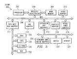
- FIG. 3 depicts a block diagram illustrating a data processing system in which the present invention may be implemented
- FIGS. 4A-4C depict pictorial diagrams illustrating a Web page with standard text links without a preview function in accordance with the prior art
- FIGS. 5A-5D depict pictorial diagrams illustrating a Web page with preview functions in accordance with the present invention.
- FIG. 6 depicts a flowchart illustrating the process of generating the preview state in accordance with the present invention.
- FIG. 1 depicts a pictorial representation of a network of data processing systems in which the present invention may be implemented.
- Network data processing system 100 is a network of computers in which the present invention may be implemented.
- Network data processing system 100 contains a network 102 , which is the medium used to provide communications links between various devices and computers connected together within network data processing system 100 .
- Network 102 may include connections, such as wire, wireless communication links, or fiber optic cables.
- a server 104 is connected to network 102 along with storage unit 106 .
- clients 108 , 110 , and 112 also are connected to network 102 .
- These clients 108 , 110 , and 112 may be, for example, personal computers or network computers.
- server 104 provides data, such as boot files, operating system images, and applications to clients 108 - 112 .
- Clients 108 , 110 , and 112 are clients to server 104 .
- Network data processing system 100 may include additional servers, clients, and other devices not shown.
- network data processing system 100 is the Internet with network 102 representing a worldwide collection of networks and gateways that use the TCP/IP suite of protocols to communicate with one another.
- network 102 representing a worldwide collection of networks and gateways that use the TCP/IP suite of protocols to communicate with one another.
- network data processing system 100 also may be implemented as a number of different types of networks, such as for example, an intranet, a local area network (LAN), or a wide area network (WAN).
- FIG. 1 is intended as an example, and not as an architectural limitation for the present invention.
- Data processing system 200 may be a symmetric multiprocessor (SMP) system including a plurality of processors 202 and 204 connected to system bus 206 . Alternatively, a single processor system may be employed. Also connected to system bus 206 is memory controller/cache 208 , which provides an interface to local memory 209 . I/O bus bridge 210 is connected to system bus 206 and provides an interface to I/O bus 212 . Memory controller/cache 208 and I/O bus bridge 210 may be integrated as depicted.
- SMP symmetric multiprocessor
- Peripheral component interconnect (PCI) bus bridge 214 connected to I/O bus 212 provides an interface to PCI local bus 216 .
- PCI bus 216 A number of modems may be connected to PCI bus 216 .
- Typical PCI bus implementations will support four PCI expansion slots or add-in connectors.
- Communications links to network computers 108 - 112 in FIG. 1 may be provided through modem 218 and network adapter 220 connected to PCI local bus 216 through add-in boards.
- Additional PCI bus bridges 222 and 224 provide interfaces for additional PCI buses 226 and 228 , from which additional modems or network adapters may be supported. In this manner, data processing system 200 allows connections to multiple network computers.
- a memory-mapped graphics adapter 230 and hard disk 232 may also be connected to I/O bus 212 as depicted, either directly or indirectly.
- FIG. 2 may vary.
- other peripheral devices such as optical disk drives and the like, also may be used in addition to or in place of the hardware depicted.
- the depicted example is not meant to imply architectural limitations with respect to the present invention.
- the data processing system depicted in FIG. 2 may be, for example, an eServer pSeries system, a product of International Business Machines Corporation in Armonk, N.Y., running the Advanced Interactive Executive (AIX) or Linux operating systems.
- AIX Advanced Interactive Executive
- Data processing system 300 is an example of a client computer.
- Data processing system 300 employs a peripheral component interconnect (PCI) local bus architecture.
- PCI peripheral component interconnect
- AGP Accelerated Graphics Port
- ISA Industry Standard Architecture
- Processor 302 and main memory 304 are connected to PCI local bus 306 through PCI bridge 308 .
- PCI bridge 308 also may include an integrated memory controller and cache memory for processor 302 . Additional connections to PCI local bus 306 may be made through direct component interconnection or through add-in boards.
- local area network (LAN) adapter 310 SCSI host bus adapter 312 , and expansion bus interface 314 are connected to PCI local bus 306 by direct component connection.
- audio adapter 316 graphics adapter 318 , and audio/video adapter 319 are connected to PCI local bus 306 by add-in boards inserted into expansion slots.
- Expansion bus interface 314 provides a connection for a keyboard and mouse adapter 320 , modem 322 , and additional memory 324 .
- Small computer system interface (SCSI) host bus adapter 312 provides a connection for hard disk drive 326 , tape drive 328 , CD-ROM drive 330 , and DVD drive 332 .
- Typical PCI local bus implementations will support three or four PCI expansion slots or add-in connectors.
- An operating system runs on processor 302 and is used to coordinate and provide control of various components within data processing system 300 in FIG. 3 .
- the operating system may be a commercially available operating system, such as Windows 2000, which is available from Microsoft Corporation.
- An object oriented programming system such as Java may run in conjunction with the operating system and provide calls to the operating system from Java programs or applications executing on data processing system 300 . “Java” is a trademark of Sun Microsystems, Inc. Instructions for the operating system, the object-oriented operating system, and applications or programs are located on storage devices, such as hard disk drive 326 , and may be loaded into main memory 304 for execution by processor 302 .
- FIG. 3 may vary depending on the implementation.
- Other internal hardware or peripheral devices such as flash ROM (or equivalent nonvolatile memory) or optical disk drives and the like, may be used in addition to or in place of the hardware depicted in FIG. 3 .
- the processes of the present invention may be applied to a multiprocessor data processing system.
- data processing system 300 may be a stand-alone system configured to be bootable without relying on some type of network communication interface, whether or not data processing system 300 comprises some type of network communication interface.
- data processing system 300 may be a Personal Digital Assistant (PDA) device, which is configured with ROM and/or flash ROM in order to provide non-volatile memory for storing operating system files and/or user-generated data.
- PDA Personal Digital Assistant
- data processing system 300 also may be a notebook computer or hand held computer in addition to taking the form of a PDA.
- data processing system 300 also may be a kiosk or a Web appliance.
- a Web-based application contains a matrix of two-state, “sticky” pushbutton controls that are used to navigate through the data represented by the matrix.
- the button controls can be in up (deselected) or down (selected) state.
- Some button controls interact with currently selected controls, other controls deselect the currently selected controls and become the only ones selected, while yet others, when deselected, cause another control to become selected. In other words, selecting or deselecting an control can have varying effects based on what else is currently selected. Of course controls other than sticky buttons may be used with the present invention.
- the invention may be applied to any type of control that indicates a selected and deselected mode.
- Non-Web based applications may also utilize the features of the present invention.
- the present invention provides a technique for providing the user with visual information as to what the next state will be if the user selects a given button control in the matrix.
- the following description uses the example of a mouse for input.
- the present invention may be applied using other input means, e.g., TrackPoint, touch pad, keyboard, etc.
- the present invention may be applied to other types of GUIs that employ on-screen button controls other than sticky buttons.
- the state will change as defined in the state table. This change is visually represented by zero or more button controls becoming selected (“down”), and zero or more controls becoming deselected (“up”), depending on the current state and which control is clicked.
- the invention allows the user to preview the next state by pressing down the mouse button, before the user releases the button to effect the click (i.e. before going to the next state resulting from the selection).
- the preview state (keyed by holding down a mouse button) all controls in the matrix are shown in the state they will be in if the click is effected by release of the mouse button.
- the preview state may also be indicated by a unique color scheme on the display to further distinguish it from the current state of the system. If the user does not want the resulting next state, the user can move the pointer off the button before releasing, thus canceling the click.
- FIG. 4A a pictorial diagram illustrating a Web page with standard text links without a preview function is depicted in accordance with the prior art.
- the example matrix is for a User Engineering portion of a web site.
- the central matrix represents a grid, with the rows representing Roles in the User Engineering process, and the columns representing Phases in the process. The intersection of a row and column represent the activities done by that Role during that Phase of the process.
- the matrix provides the central means of process navigation on the web site.
- the gray Role by Phase control 401 in the upper left corner is selected and appears down. If the user wishes to go to the intersection of the first Role 402 and second Phase 403 , one way to get there is to click on the link text in that cell of the matrix, “User Experience Objectives & Metrics” 404 . Like all link text on the Web, when a user presses a mouse button down with the pointer on the link (but before the button is released), there is no indication of the visual state that the click will produce. The state of holding down the button with the pointer on the link text is seen in FIG. 4B .
- FIG. 4C depicts the web page display that results when the user releases the mouse button, with the contents of the clicked cell replacing the central matrix from FIGS. 4A and 4B .
- the Role by Phase control 401 is no longer selected (down), while the first Role control 402 and second Phase control 403 are shown as selected.
- the title 408 in the content area also shows where the user is, in that it concatenates the selected Role and Phase. Therefore, there are multiple ways for the user to know his or her location in the matrix.
- the present invention provides a visual indication of the result of a click, before the click is processed, giving the user a chance to cancel the click if it is not going to result in the desired action.
- FIG. 5A a pictorial diagram illustrating a Web page with preview functions is depicted in accordance with the present invention.
- FIG. 5A shows the same Web page content as FIG. 4C .
- the user has pressed the mouse button down with the pointer 405 on the first Phase control 408 (“Business Opportunity”), thus revealing the preview of the next state.
- Phase control 408 (“Business Opportunity”)
- the preview state shows that the second Phase control 403 will become deselected, and the first Phase 408 and first Role 402 controls will be selected.
- the dark bars 406 and 407 are still present in the preview, thus indicating the current state as the user is viewing the preview state.
- FIG. 5B depicts an alternate preview state to the one depicted in FIG. 5A .
- the user has pressed the mouse button down with the pointer 405 over the second Phase control 403 (which is currently selected).
- the resulting preview state illustrated in FIG. 5B shows that the second Phase control 403 will become deselected, while the first Role control 402 stays selected, if the user releases the mouse button.
- FIG. 5 B helps illustrate how the Role and Phase control are “sticky” buttons, meaning they can be selected with a click and then deselected with another click.
- FIG. 5C depicts the resulting state previewed in FIG. 5B :
- the second Phase control 403 has been deselected, while the first Role control 402 remains selected.
- the content of the Web page depicted in FIG. 5C has changed from the content of FIGS. 5A and 5B . Because only a Role control 402 is selected, the content of the Web page now includes a discussion about that Role (“User Experience Leadership”) as it relates to all Phases, not just the “Understanding Users” Phase.
- Role User Experience Leadership
- the Web page depicted in FIG. 5D contains the same content as FIG. 5C but shows the preview state that results when the user presses the mouse button with the pointer 405 on the only selected control, the first Role control 402 .
- the first Role control 402 can be deselected simply by clicking on it.
- the preview if the user releases the mouse button, the first Role control 402 will become deselected and the Role by Phase control 401 in the upper left corner will become selected. If the user completes the click on the first Role control 402 , the resulting state (as indicated by the preview) will take the user back to the Web page depicted in FIG. 4A .
- a style sheet is a master page layout used in document creation systems, such as word processing and the Web.
- the style sheet is a file that stores margins, tabs, fonts, headers, footers, and other visual layout settings for a particular category of object.
- the styles for the affected controls are changed when the user starts a click, and changed back to what they were if the click is canceled. If the click is completed, another web page is displayed showing the new content and the control states that were previewed.
- the mechanism used to change styles is standard HTML/style sheet syntax and is well known to web programmers.
- the process starts with the user pressing down on an input button (e.g., mouse button) while the pointer is on one of the control (step 601 ).
- the system determines if the control in question is currently selected (down) (step 602 ).
- control If the control is currently selected, its style is changed such that it appears deselected (up) (step 603 ). The system then determines if this results in any control remaining selected (step 604 ). If there are any remaining selected, the process proceeds to step 612 . However, if there are no control remaining selected, the system changes the style of the Role by Phase control to appear selected (step 605 ), and then proceeds to step 612 .
- step 606 the system changes the style of the control to appear selected (step 606 ), and then determines if the control clicked on is the Role by Phase control (step 607 ). If it is the Role by Phase control, the system changes the styles of any selected Role and Phase controls to appear deselected (step 608 ), and then proceeds to step 612 .
- the system determines if it is a Role or Phase control (step 609 ). If it is a Role control, the system changes the style of any other selected Role control to appear deselected (step 610 ), and proceeds to step 612 .
- step 611 the system changes the style of any other selected Phase button to appear deselected (step 611 ), and proceeds to step 612 .
- the user releases the input button (step 612 ). If the pointer is still on the control when the user releases the button, the system executes the action triggered by the click (step 614 ). If the pointer has been moved off the control when the button is released, the system cancels the style changes (step 615 ).
- the present invention provides users with additional information that can help them avoid states they do not want. In a Web application, this saves users the load time for pages they do not want, as well as the load time to go back to the previous page. Being able to preview the next state also allows users to investigate and discover exactly how the matrix functions, and the results of various actions, without having to load other pages in the course of that investigation. This can provide significant time and productivity savings.
- the Web page matrix described above is merely a convenient example of how the present invention may be implemented. It should be emphasized that the present invention may be implemented with any GUI that displays interacting control objects that can display alternate states. For example, instead of sticky buttons that appear up or down, the controls might change color to indicate selected and deselected states.
- the invention may be implemented with other input devices.
- the user may simply use a keyboard.
- a group of keys may be specified as direction keys for selecting controls on screen. These key may be specified either by the application or the user.
- the enter key can be used for input, wherein the user holds the enter key to see the preview state.
Abstract
Description
Claims (7)
Priority Applications (2)
| Application Number | Priority Date | Filing Date | Title |
|---|---|---|---|
| US10/205,106 US7383515B2 (en) | 2002-07-25 | 2002-07-25 | Previewing next state based on potential action in current state |
| US12/116,789 US8112723B2 (en) | 2002-07-25 | 2008-05-07 | Previewing next state based on potential action in current state |
Applications Claiming Priority (1)
| Application Number | Priority Date | Filing Date | Title |
|---|---|---|---|
| US10/205,106 US7383515B2 (en) | 2002-07-25 | 2002-07-25 | Previewing next state based on potential action in current state |
Related Child Applications (1)
| Application Number | Title | Priority Date | Filing Date |
|---|---|---|---|
| US12/116,789 Continuation US8112723B2 (en) | 2002-07-25 | 2008-05-07 | Previewing next state based on potential action in current state |
Publications (2)
| Publication Number | Publication Date |
|---|---|
| US20040017402A1 US20040017402A1 (en) | 2004-01-29 |
| US7383515B2 true US7383515B2 (en) | 2008-06-03 |
Family
ID=30769989
Family Applications (2)
| Application Number | Title | Priority Date | Filing Date |
|---|---|---|---|
| US10/205,106 Expired - Fee Related US7383515B2 (en) | 2002-07-25 | 2002-07-25 | Previewing next state based on potential action in current state |
| US12/116,789 Active 2024-11-21 US8112723B2 (en) | 2002-07-25 | 2008-05-07 | Previewing next state based on potential action in current state |
Family Applications After (1)
| Application Number | Title | Priority Date | Filing Date |
|---|---|---|---|
| US12/116,789 Active 2024-11-21 US8112723B2 (en) | 2002-07-25 | 2008-05-07 | Previewing next state based on potential action in current state |
Country Status (1)
| Country | Link |
|---|---|
| US (2) | US7383515B2 (en) |
Cited By (10)
| Publication number | Priority date | Publication date | Assignee | Title |
|---|---|---|---|---|
| US20060206838A1 (en) * | 1999-11-15 | 2006-09-14 | Marlo Longstreet 2003 Irrevocable Trust | Apparatus and method to navigate interactive television using unique inputs with a remote control |
| US20060212811A1 (en) * | 1999-11-15 | 2006-09-21 | Gottfurcht Elliot A | Apparatus and method for simple wide-area network navigation |
| US20070021129A1 (en) * | 2005-07-21 | 2007-01-25 | Sony Corporation | Information processing apparatus, processing method therefor, program allowing computer to execute the method |
| US20080209362A1 (en) * | 2002-07-25 | 2008-08-28 | International Business Machines Corporation | Previewing Next State Based on Potential Action in Current State |
| US20090219294A1 (en) * | 2008-02-29 | 2009-09-03 | Microsoft Corporation | Visual state manager for control skinning |
| US20110179388A1 (en) * | 2010-01-15 | 2011-07-21 | Apple Inc. | Techniques And Systems For Enhancing Touch Screen Device Accessibility Through Virtual Containers And Virtually Enlarged Boundaries |
| US8797330B1 (en) | 2013-10-18 | 2014-08-05 | Google Inc. | Systems and methods for detecting and animating changes in application state |
| US10732829B2 (en) | 2011-06-05 | 2020-08-04 | Apple Inc. | Devices, methods, and graphical user interfaces for providing control of a touch-based user interface absent physical touch capabilities |
| US10986252B2 (en) | 2015-06-07 | 2021-04-20 | Apple Inc. | Touch accommodation options |
| US11947792B2 (en) | 2011-12-29 | 2024-04-02 | Apple Inc. | Devices, methods, and graphical user interfaces for providing multitouch inputs and hardware-based features using a single touch input |
Families Citing this family (8)
| Publication number | Priority date | Publication date | Assignee | Title |
|---|---|---|---|---|
| US7849419B2 (en) * | 2004-11-16 | 2010-12-07 | Sas Institute Inc. | Computer-implemented graphical user interface previews |
| US8082327B2 (en) * | 2007-04-02 | 2011-12-20 | Binu Pty Ltd | Systems methods and apparatuses for providing applications style functionality to a user |
| US8074185B2 (en) * | 2007-05-16 | 2011-12-06 | Sherwood Electronics Laboratories, Inc. | System and method for displaying and manipulating hierarchically linked data in a genealogy database using a graphical interface |
| US20100306677A1 (en) * | 2009-05-26 | 2010-12-02 | Hargobind Khalsa | Method for activating objects in a mark-up language environment |
| US9330503B2 (en) * | 2009-06-19 | 2016-05-03 | Microsoft Technology Licensing, Llc | Presaging and surfacing interactivity within data visualizations |
| US8866818B2 (en) | 2009-06-19 | 2014-10-21 | Microsoft Corporation | Composing shapes and data series in geometries |
| US20170229146A1 (en) * | 2016-02-10 | 2017-08-10 | Justin Garak | Real-time content editing with limited interactivity |
| CN113311982A (en) * | 2021-05-25 | 2021-08-27 | 维沃移动通信有限公司 | Information selection method and device |
Citations (7)
| Publication number | Priority date | Publication date | Assignee | Title |
|---|---|---|---|---|
| US5687331A (en) * | 1995-08-03 | 1997-11-11 | Microsoft Corporation | Method and system for displaying an animated focus item |
| US6222541B1 (en) * | 1998-01-20 | 2001-04-24 | International Business Machines Corporation | Method and apparatus for fast-path location and selection of links |
| US6330577B1 (en) * | 1997-10-15 | 2001-12-11 | Samsung Electronics Co., Ltd. | Apparatus and method for displaying font information by using preview window |
| US20020054144A1 (en) * | 2000-05-31 | 2002-05-09 | Morris-Yates Timothy Mark | Method for active feedback |
| US6583798B1 (en) * | 2000-07-21 | 2003-06-24 | Microsoft Corporation | On-object user interface |
| US20030146939A1 (en) * | 2001-09-24 | 2003-08-07 | John Petropoulos | Methods and apparatus for mouse-over preview of contextually relevant information |
| US7076738B2 (en) * | 2001-03-02 | 2006-07-11 | Semantic Compaction Systems | Computer device, method and article of manufacture for utilizing sequenced symbols to enable programmed application and commands |
Family Cites Families (2)
| Publication number | Priority date | Publication date | Assignee | Title |
|---|---|---|---|---|
| US6953886B1 (en) * | 1998-06-17 | 2005-10-11 | Looney Productions, Llc | Media organizer and entertainment center |
| US7383515B2 (en) | 2002-07-25 | 2008-06-03 | International Business Machines Corporation | Previewing next state based on potential action in current state |
-
2002
- 2002-07-25 US US10/205,106 patent/US7383515B2/en not_active Expired - Fee Related
-
2008
- 2008-05-07 US US12/116,789 patent/US8112723B2/en active Active
Patent Citations (7)
| Publication number | Priority date | Publication date | Assignee | Title |
|---|---|---|---|---|
| US5687331A (en) * | 1995-08-03 | 1997-11-11 | Microsoft Corporation | Method and system for displaying an animated focus item |
| US6330577B1 (en) * | 1997-10-15 | 2001-12-11 | Samsung Electronics Co., Ltd. | Apparatus and method for displaying font information by using preview window |
| US6222541B1 (en) * | 1998-01-20 | 2001-04-24 | International Business Machines Corporation | Method and apparatus for fast-path location and selection of links |
| US20020054144A1 (en) * | 2000-05-31 | 2002-05-09 | Morris-Yates Timothy Mark | Method for active feedback |
| US6583798B1 (en) * | 2000-07-21 | 2003-06-24 | Microsoft Corporation | On-object user interface |
| US7076738B2 (en) * | 2001-03-02 | 2006-07-11 | Semantic Compaction Systems | Computer device, method and article of manufacture for utilizing sequenced symbols to enable programmed application and commands |
| US20030146939A1 (en) * | 2001-09-24 | 2003-08-07 | John Petropoulos | Methods and apparatus for mouse-over preview of contextually relevant information |
Cited By (17)
| Publication number | Priority date | Publication date | Assignee | Title |
|---|---|---|---|---|
| US20060212811A1 (en) * | 1999-11-15 | 2006-09-21 | Gottfurcht Elliot A | Apparatus and method for simple wide-area network navigation |
| US20060206838A1 (en) * | 1999-11-15 | 2006-09-14 | Marlo Longstreet 2003 Irrevocable Trust | Apparatus and method to navigate interactive television using unique inputs with a remote control |
| US8112723B2 (en) | 2002-07-25 | 2012-02-07 | International Business Machines Corporation | Previewing next state based on potential action in current state |
| US20080209362A1 (en) * | 2002-07-25 | 2008-08-28 | International Business Machines Corporation | Previewing Next State Based on Potential Action in Current State |
| US20070021129A1 (en) * | 2005-07-21 | 2007-01-25 | Sony Corporation | Information processing apparatus, processing method therefor, program allowing computer to execute the method |
| US7614017B2 (en) * | 2005-07-21 | 2009-11-03 | Sony Corporation | Information processing apparatus, processing method therefor, program allowing computer to execute the method |
| US8314801B2 (en) * | 2008-02-29 | 2012-11-20 | Microsoft Corporation | Visual state manager for control skinning |
| US20090219294A1 (en) * | 2008-02-29 | 2009-09-03 | Microsoft Corporation | Visual state manager for control skinning |
| US20110179388A1 (en) * | 2010-01-15 | 2011-07-21 | Apple Inc. | Techniques And Systems For Enhancing Touch Screen Device Accessibility Through Virtual Containers And Virtually Enlarged Boundaries |
| US8386965B2 (en) * | 2010-01-15 | 2013-02-26 | Apple Inc. | Techniques and systems for enhancing touch screen device accessibility through virtual containers and virtually enlarged boundaries |
| US10732829B2 (en) | 2011-06-05 | 2020-08-04 | Apple Inc. | Devices, methods, and graphical user interfaces for providing control of a touch-based user interface absent physical touch capabilities |
| US11354032B2 (en) | 2011-06-05 | 2022-06-07 | Apple Inc. | Devices, methods, and graphical user interfaces for providing control of a touch-based user interface absent physical touch capabilities |
| US11775169B2 (en) | 2011-06-05 | 2023-10-03 | Apple Inc. | Devices, methods, and graphical user interfaces for providing control of a touch-based user interface absent physical touch capabilities |
| US11947792B2 (en) | 2011-12-29 | 2024-04-02 | Apple Inc. | Devices, methods, and graphical user interfaces for providing multitouch inputs and hardware-based features using a single touch input |
| US8797330B1 (en) | 2013-10-18 | 2014-08-05 | Google Inc. | Systems and methods for detecting and animating changes in application state |
| US10986252B2 (en) | 2015-06-07 | 2021-04-20 | Apple Inc. | Touch accommodation options |
| US11470225B2 (en) | 2015-06-07 | 2022-10-11 | Apple Inc. | Touch accommodation options |
Also Published As
| Publication number | Publication date |
|---|---|
| US8112723B2 (en) | 2012-02-07 |
| US20080209362A1 (en) | 2008-08-28 |
| US20040017402A1 (en) | 2004-01-29 |
Similar Documents
| Publication | Publication Date | Title |
|---|---|---|
| US8112723B2 (en) | Previewing next state based on potential action in current state | |
| US11385786B2 (en) | Spin control user interface for selecting options | |
| US5754809A (en) | Perspective windowing technique for computer graphical user interface | |
| US6025844A (en) | Method and system for creating dynamic link views | |
| US6104401A (en) | Link filters | |
| JP6018045B2 (en) | Temporary formatting and graphing of selected data | |
| US5325481A (en) | Method for creating dynamic user panels in an iconic programming system | |
| US7917864B2 (en) | Automatically scaling the information and controls in navigation tabs per available window area | |
| US7346855B2 (en) | Method and system for switching between multiple computer applications | |
| US6147683A (en) | Graphical selection marker and method for lists that are larger than a display window | |
| JP2732557B2 (en) | Method and data processing system for changing function of GUI | |
| US20090158166A1 (en) | Method, system, and computer program product for automatic rearrangement of modules based on user interaction | |
| US7549130B2 (en) | Pattern-based keyboard controls | |
| US20090150823A1 (en) | Apparatus and Method for Improved Window Management in a Grid Management System | |
| JPH0944335A (en) | Method and device for display of image map and original outward appearance | |
| JPH08137646A (en) | Method and system for displaying dialogue box | |
| US11288337B2 (en) | Object selection in web page authoring | |
| JP2008176479A (en) | Information processor, information processing method and information processing program | |
| KR20200088152A (en) | Apparatus and method for Implementing Responsive Web using Template | |
| US8745512B2 (en) | Method and computer-readable medium for interacting with a portion of an electronic document | |
| JP2755372B2 (en) | Display system with nested objects | |
| JPH0916364A (en) | Context -sensitive menu system / menu operation | |
| JPH04257919A (en) | Graphic processing method | |
| JP2004110410A (en) | Display method of chart, display system, and computer program | |
| KR20010044214A (en) | User interfacing method using navigation bar |
Legal Events
| Date | Code | Title | Description |
|---|---|---|---|
| AS | Assignment |
Owner name: INTERNATIONAL BUSINESS MACHINES CORPORATION, NEW Y Free format text: ASSIGNMENT OF ASSIGNORS INTEREST;ASSIGNORS:BARDON, DIDIER D.;BERRY, RICHARD EDMOND;MORGAN, SCOTT ANTHONY;AND OTHERS;REEL/FRAME:013168/0224;SIGNING DATES FROM 20020710 TO 20020723 |
|
| FEPP | Fee payment procedure |
Free format text: PAYOR NUMBER ASSIGNED (ORIGINAL EVENT CODE: ASPN); ENTITY STATUS OF PATENT OWNER: LARGE ENTITY |
|
| FPAY | Fee payment |
Year of fee payment: 4 |
|
| REMI | Maintenance fee reminder mailed | ||
| LAPS | Lapse for failure to pay maintenance fees | ||
| STCH | Information on status: patent discontinuation |
Free format text: PATENT EXPIRED DUE TO NONPAYMENT OF MAINTENANCE FEES UNDER 37 CFR 1.362 |
|
| FP | Lapsed due to failure to pay maintenance fee |
Effective date: 20160603 |
|
| AS | Assignment |
Owner name: DAEDALUS GROUP LLC, NEW YORK Free format text: ASSIGNMENT OF ASSIGNORS INTEREST;ASSIGNOR:INTERNATIONAL BUSINESS MACHINES CORPORATION;REEL/FRAME:051018/0649 Effective date: 20191106 |
|
| AS | Assignment |
Owner name: DAEDALUS BLUE LLC, NEW YORK Free format text: ASSIGNMENT OF ASSIGNORS INTEREST;ASSIGNOR:DAEDALUS GROUP, LLC;REEL/FRAME:051737/0191 Effective date: 20200128 |
|
| AS | Assignment |
Owner name: TERRACE LICENSING LLC, TEXAS Free format text: ASSIGNMENT OF ASSIGNORS INTEREST;ASSIGNOR:DAEDALUS BLUE LLC;REEL/FRAME:058895/0322 Effective date: 20211129 |
|
| AS | Assignment |
Owner name: TERRACE LICENSING LLC, TEXAS Free format text: ASSIGNMENT OF ASSIGNORS INTEREST;ASSIGNOR:DAEDALUS BLUE LLC;REEL/FRAME:058902/0482 Effective date: 20211129 |