US7357520B2 - Image projection apparatus - Google Patents
Image projection apparatus Download PDFInfo
- Publication number
- US7357520B2 US7357520B2 US11/561,268 US56126806A US7357520B2 US 7357520 B2 US7357520 B2 US 7357520B2 US 56126806 A US56126806 A US 56126806A US 7357520 B2 US7357520 B2 US 7357520B2
- Authority
- US
- United States
- Prior art keywords
- projector
- image medium
- light source
- lens
- housing
- Prior art date
- Legal status (The legal status is an assumption and is not a legal conclusion. Google has not performed a legal analysis and makes no representation as to the accuracy of the status listed.)
- Expired - Fee Related
Links
Images


Classifications
-
- G—PHYSICS
- G03—PHOTOGRAPHY; CINEMATOGRAPHY; ANALOGOUS TECHNIQUES USING WAVES OTHER THAN OPTICAL WAVES; ELECTROGRAPHY; HOLOGRAPHY
- G03B—APPARATUS OR ARRANGEMENTS FOR TAKING PHOTOGRAPHS OR FOR PROJECTING OR VIEWING THEM; APPARATUS OR ARRANGEMENTS EMPLOYING ANALOGOUS TECHNIQUES USING WAVES OTHER THAN OPTICAL WAVES; ACCESSORIES THEREFOR
- G03B21/00—Projectors or projection-type viewers; Accessories therefor
- G03B21/14—Details
- G03B21/20—Lamp housings
- G03B21/2066—Reflectors in illumination beam
-
- F—MECHANICAL ENGINEERING; LIGHTING; HEATING; WEAPONS; BLASTING
- F16—ENGINEERING ELEMENTS AND UNITS; GENERAL MEASURES FOR PRODUCING AND MAINTAINING EFFECTIVE FUNCTIONING OF MACHINES OR INSTALLATIONS; THERMAL INSULATION IN GENERAL
- F16M—FRAMES, CASINGS OR BEDS OF ENGINES, MACHINES OR APPARATUS, NOT SPECIFIC TO ENGINES, MACHINES OR APPARATUS PROVIDED FOR ELSEWHERE; STANDS; SUPPORTS
- F16M11/00—Stands or trestles as supports for apparatus or articles placed thereon Stands for scientific apparatus such as gravitational force meters
- F16M11/02—Heads
- F16M11/04—Means for attachment of apparatus; Means allowing adjustment of the apparatus relatively to the stand
- F16M11/06—Means for attachment of apparatus; Means allowing adjustment of the apparatus relatively to the stand allowing pivoting
- F16M11/10—Means for attachment of apparatus; Means allowing adjustment of the apparatus relatively to the stand allowing pivoting around a horizontal axis
-
- F—MECHANICAL ENGINEERING; LIGHTING; HEATING; WEAPONS; BLASTING
- F16—ENGINEERING ELEMENTS AND UNITS; GENERAL MEASURES FOR PRODUCING AND MAINTAINING EFFECTIVE FUNCTIONING OF MACHINES OR INSTALLATIONS; THERMAL INSULATION IN GENERAL
- F16M—FRAMES, CASINGS OR BEDS OF ENGINES, MACHINES OR APPARATUS, NOT SPECIFIC TO ENGINES, MACHINES OR APPARATUS PROVIDED FOR ELSEWHERE; STANDS; SUPPORTS
- F16M11/00—Stands or trestles as supports for apparatus or articles placed thereon Stands for scientific apparatus such as gravitational force meters
- F16M11/02—Heads
- F16M11/18—Heads with mechanism for moving the apparatus relatively to the stand
-
- F—MECHANICAL ENGINEERING; LIGHTING; HEATING; WEAPONS; BLASTING
- F21—LIGHTING
- F21V—FUNCTIONAL FEATURES OR DETAILS OF LIGHTING DEVICES OR SYSTEMS THEREOF; STRUCTURAL COMBINATIONS OF LIGHTING DEVICES WITH OTHER ARTICLES, NOT OTHERWISE PROVIDED FOR
- F21V21/00—Supporting, suspending, or attaching arrangements for lighting devices; Hand grips
- F21V21/08—Devices for easy attachment to any desired place, e.g. clip, clamp, magnet
- F21V21/0824—Ground spikes
-
- G—PHYSICS
- G03—PHOTOGRAPHY; CINEMATOGRAPHY; ANALOGOUS TECHNIQUES USING WAVES OTHER THAN OPTICAL WAVES; ELECTROGRAPHY; HOLOGRAPHY
- G03B—APPARATUS OR ARRANGEMENTS FOR TAKING PHOTOGRAPHS OR FOR PROJECTING OR VIEWING THEM; APPARATUS OR ARRANGEMENTS EMPLOYING ANALOGOUS TECHNIQUES USING WAVES OTHER THAN OPTICAL WAVES; ACCESSORIES THEREFOR
- G03B21/00—Projectors or projection-type viewers; Accessories therefor
- G03B21/14—Details
- G03B21/145—Housing details, e.g. position adjustments thereof
-
- G—PHYSICS
- G03—PHOTOGRAPHY; CINEMATOGRAPHY; ANALOGOUS TECHNIQUES USING WAVES OTHER THAN OPTICAL WAVES; ELECTROGRAPHY; HOLOGRAPHY
- G03B—APPARATUS OR ARRANGEMENTS FOR TAKING PHOTOGRAPHS OR FOR PROJECTING OR VIEWING THEM; APPARATUS OR ARRANGEMENTS EMPLOYING ANALOGOUS TECHNIQUES USING WAVES OTHER THAN OPTICAL WAVES; ACCESSORIES THEREFOR
- G03B21/00—Projectors or projection-type viewers; Accessories therefor
- G03B21/14—Details
- G03B21/28—Reflectors in projection beam
-
- G—PHYSICS
- G03—PHOTOGRAPHY; CINEMATOGRAPHY; ANALOGOUS TECHNIQUES USING WAVES OTHER THAN OPTICAL WAVES; ELECTROGRAPHY; HOLOGRAPHY
- G03B—APPARATUS OR ARRANGEMENTS FOR TAKING PHOTOGRAPHS OR FOR PROJECTING OR VIEWING THEM; APPARATUS OR ARRANGEMENTS EMPLOYING ANALOGOUS TECHNIQUES USING WAVES OTHER THAN OPTICAL WAVES; ACCESSORIES THEREFOR
- G03B23/00—Devices for changing pictures in viewing apparatus or projectors
- G03B23/08—Devices for changing pictures in viewing apparatus or projectors in which pictures are attached to a movable carrier
- G03B23/10—Devices for changing pictures in viewing apparatus or projectors in which pictures are attached to a movable carrier drum or disc carrier
-
- F—MECHANICAL ENGINEERING; LIGHTING; HEATING; WEAPONS; BLASTING
- F16—ENGINEERING ELEMENTS AND UNITS; GENERAL MEASURES FOR PRODUCING AND MAINTAINING EFFECTIVE FUNCTIONING OF MACHINES OR INSTALLATIONS; THERMAL INSULATION IN GENERAL
- F16M—FRAMES, CASINGS OR BEDS OF ENGINES, MACHINES OR APPARATUS, NOT SPECIFIC TO ENGINES, MACHINES OR APPARATUS PROVIDED FOR ELSEWHERE; STANDS; SUPPORTS
- F16M2200/00—Details of stands or supports
- F16M2200/02—Locking means
- F16M2200/021—Locking means for rotational movement
- F16M2200/022—Locking means for rotational movement by friction
Definitions
- This invention relates to devices used to project images embodied on transparent polymeric film onto one or more viewing surfaces by shining a light through the image embodied on the film. More particularly, the invention relates to projectors used to project thematic images singly, in either a static or serial display, onto a viewing surface or to project multiple views of an image simultaneously onto a plurality of viewing surfaces.
- the projection of images using light is a well known and popular way to decorate or entertain, especially during the holidays, seasonal events or special occasions.
- a relatively small image can be enlarged to many times its original size and displayed upon a surface such as a wall, garage door, sheet, screen or the like.
- Drawbacks to the practice of projecting images using light include the high cost of conventional projectors, many of which cannot be used outdoors in inclement weather, and the fact that such projectors typically require some intervention by the user in order to change the image being projected. Projectors are therefore needed that are economical to manufacture and use, that can be used outdoors without risk of injury or damage, and that can display images singly, serially, or simultaneously on multiple surfaces without user intervention.
- FIG. 1 is a front perspective view of a preferred projector of the invention
- FIG. 2 is a right side elevation view of the projector of FIG. 1 ;
- FIG. 3 is a rear elevation view of the projector of FIG. 1 ;
- FIG. 4 is a left side elevation view of the projector of FIG. 1 ;
- FIG. 5 is an exploded perspective view of the projector of FIG. 1 ;
- FIG. 6 is a front perspective view of another preferred projector of the invention that is modified to rotate an image wheel through the light path;
- FIG. 7 is a partial exploded view of the projector of FIG. 6 ;
- FIG. 8 is an exploded perspective view, partially broken away, of another preferred projector assembly of the invention wherein a mirror ball is rotatably mounted in the light path emanating from the projector,
- FIG. 9 is an exploded view of an alternate embodiment of the projector assembly including the mirror ball,
- FIG. 10 is an exploded view of the projector support assembly member of the alternate embodiment of FIG. 9
- FIG. 11 a is a front view of one section of a shield of the alternate embodiment of FIG. 9
- FIG. 11 b is a side view of one section of a shield of the alternate embodiment of FIG. 9 .
- FIG. 12 is a side view of an assembled version of the alternate embodiment of FIG. 9 .
- FIG. 13 is an exploded view of a mirror ball and shield assembly
- FIG. 14 is an exploded view of a mirror ball
- FIG. 15 a is a front view of components of the mirror ball
- FIG. 15 b is a side view of components of the mirror ball
- FIG. 16 is a perspective view of the mirror ball with gear rotation indicators
- FIG. 17 a is a front view of a barrel shaped configuration of the mirror ball
- FIG. 17 b is a side view of a barrel shaped configuration of the mirror ball
- FIG. 18 is a side view of a projector using an alternate embodiment of a support member
- FIG. 19 is a side view of a projector and mirror ball assembly using an alternate embodiment of a support member
- FIG. 20 is a bottom view of the alternate embodiment of a support member
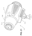
- FIG. 21 is a perspective view of another embodiment of the projector having two image sources
- FIG. 22 is an exploded view of the projector of FIG. 21 ;
- FIG. 23 is a rear view of the projector of FIG. 21 ;
- FIG. 24 is an alternate perspectivel view of the projector of FIG. 21 ;
- FIG. 25 is a perspective view of a screen upon which images may be displayed.
- projector 10 preferably comprises a polymeric housing 12 supporting a light source 14 at one end and a lens tube 16 , most preferably containing a biconvex lens 18 , at the other.
- Housing 12 is preferably injection molded from an impact resistant polymer and is most preferably molded in two halves 20 and 22 that are joined during assembly with screws 24 or other similarly effective fasteners
- the imaginary line between light source 14 and lens 18 establishes a light path that, when extended beyond projector 10 , continues to a viewing surface upon which an image is to be projected
- Housing 12 preferably further comprises an image medium support assembly 26 that is disposed between light source 14 and lens 18 .
- Image medium support assembly 26 supports an image medium 28 such as, for example, a circular disk comprising a slide film or transparency in an image window through which light emanating from light source 14 is directed toward lens 18 .
- Lens tube 16 is most preferably threaded into engagement with housing 12 in such manner that the focal length between image medium 28 and lens 18 can be adjusted within predetermined limits.
- Light source 14 preferably contains an electric lamp 30 and is threaded into engagement with the end of housing opposite lens tube 16 , When removed, light source 14 also provides access to image medium support assembly 26 so that image medium 28 can be changed as desired. Vents or louvers 32 are desirably provided in housing 12 and in light source 14 to facilitate convective cooling of lamp 30 during use.
- Projector 10 preferably further comprises a projector support member 34 to which housing 12 is connected in such manner that the angle of the light path relative to an underlying support surface can be adjusted easily by the user.
- the connecting mechanism comprises opposed engagement members 38 , 40 having interlocking teeth and coaxially aligned apertures through which a threaded bolt 42 can be inserted and tightened using wing nut 44 when projector housing 12 is in the preferred angular position.
- Projector support member 34 preferably further comprises a tubular member 46 containing a transformer 48 that desirably converts standard household electrical current to a lower voltage for use with lamp 30 of projector 10 ,
- One electrical conductor 50 supplies electrical current to transformer 48 and another electrical conductor 52 supplies the converted current to plug 54 on the back of light source 14 of housing 12 .
- Projector support member 34 preferably further comprises mounting stake 56 having footrest 58 to facilitate insertion of mounting stake 56 into the ground for outdoor use on earthen surface 36 ,
- projector support member 34 is described above in relation to a preferred embodiment intended for use with an earthen support surface 36 , it will be apparent to those of ordinary skill in the art upon reading this disclosure that projector support members having other physical configurations can likewise be provided for use with other underlying support surfaces for projector 10 .
- a projector is disclosed that is substantially as described above but modified to serially advance different images into the light path without user intervention.
- a preferred modification for achieving this function this the provision of a small electric motor inside the housing with a rotating shaft that causes a wheel comprising multiple fixed images to rotate the same or different images sequentially through the light path of the projector. This rotation can be accomplished continuously or intermittently by the provision of appropriate conventional linkage and control mechanisms well known to those of skill in the art.
- projector 60 preferably comprises an enlarged molded plastic housing 62 , again having a light source 64 disposed at one end and a lens tube 66 containing lens 68 at the other, thereby defining a light path through the projector.
- Projector 60 is preferably attached by mounting stud 70 to support member 72 , which is shown as having a stake 74 for insertion into an earthen surface for outdoor use. Electrical power cords and a transformer as previously described for projector 10 are also desirably utilized with this embodiment of the invention but are not depicted in the simplified drawing of FIG. 6 .
- housing 62 of projector 60 preferably comprises an electric motor 78 that rotates shaft 76 , which is offset from the light path established by light source 64 and lens 68 .
- Image medium support assembly 86 comprising image window 88 cooperates with rotatable shaft 76 to rotate image wheel 80 .
- Image wheel 80 further comprises a centrally disposed aperture 82 that engages shaft 76 so that image wheel 80 is rotated through image window 88 whenever motor 78 is energized. Electrical cords, transformers and plugs are also not shown to simplify the illustration but can be provided as for projector 10 as previously described.
- Image wheel 80 preferably comprises a plurality of images 84 that are arcuately spaced apart near its periphery to facilitate the serial advancement of such images into image window 88 as wheel 80 rotates. Images 84 can be the same or different.
- Cartridge 90 is also desirably provided so that a single image or color filter can be installed inside image medium support assembly 86 in place of, or in addition to, using image wheel 80 if desired.
- a projector assembly comprising a low cost projector substantially as described above but modified to simultaneously project a single image in a plurality of directions after the projected light beam exits the projector housing.
- This embodiment of the invention utilizes a frame assembly that aligns the projector with a rotating mirror ball that simultaneously redirects the projected image in many different directions and continuously changes the image being projected onto a particular spot on surrounding viewing surfaces.
- This embodiment of the invention is particularly preferred for indoor use where the image can be directed against both walls and ceiling at the same time
- FIG. 8 an exploded view is shown of a projector assembly 92 comprising projector 94 , which can be mounted in fixed relation to support frame 96 .
- Support frame 96 can in turn be adjustably mounted to support member 118 using bolt 120 to vary the inclination of frame 96 as desired,
- Frame member 96 preferably further comprises, in spaced apart relation to projector 94 , a mounting bracket 102 secured to frame 96 by bolt 103 inserted through aperture 106 , or by any other similarly effective means or mechanism.
- a multi-faceted reflective element such as mirror ball 108 is preferably supported on an axle 110 that is rotatably mounted in clevis members 104 , 106 through apertures 112 , 113 in such manner that axle 110 can be rotated by electric motor to slowly turn mirror ball 108 .
- Mirror ball 108 preferably comprises a plurality of small mirrored surfaces 116 oriented in many different directions.
- the lighting effect achieved through the use of projector 94 in this manner under conditions of low ambient light is to simultaneously direct the projected image against many viewing surfaces, seemingly multiplying the projected image many times over.
- mirror ball 108 is rotated, the effect is further enhanced by imparting motion to the multiple projected images.
- FIGS. 9 and 12 show an alternate embodiment of the projector 200 which includes a reflector element 208 which is shielded and rotated from its interior.
- the projector 260 may be supported upon frame member 296 .
- the reflective element 208 may be indirectly supported by the frame member 296 .
- the reflective element 208 may be supported by a shield 209 which is in turn supported by the frame member 296 .
- An easy-to-loosen nut 210 is used to attach the shield 209 to the frame member 296 such that the shield 209 and reflective element 208 may be easily rotated to new positions.
- a key 211 may be included which restricts the shield 209 and reflective element 208 from being rotated in multiple three-hundred and sixty degree circuits in a single direction. As a result the entanglement of an electrical cord between the transformer and reflective element is avoided.
- the shield 209 may be fabricated in two portions capable of being joined together.
- the shield 209 may include a support aperture or indentation 211 which may support the reflective element 208 .
- the shield 209 functions as a support device, and also blocks some of the light reflected off of the reflective element 208 which was reflected off in an undesired direction.
- a stand 230 which includes two similarly shaped tubular members 231 and 232 .
- the tubular members 231 and 232 may be bent into a V-shape with a flat bottom.
- the tubular members 231 and 232 may be abutted and screwed together.
- the stand 230 may also include a bracket 233 , vertical chamber 234 and adapter 235 .
- the bracket 233 is attachable to both the tubular members 231 and 232 as well as the vertical chamber 234 .
- the vertical chamber 234 is preferably hollow and may hold a transformer.
- the adapter 235 is attachable to the vertical chamber 234 on one end and either the support member 296 or a projector 260 if used alone, on its opposite end.
- one or more J-shaped stakes may be used to hold the stand in place. The longer portion of the J-shaped stake enters the ground while the shorter portion hooks one of the tubular members 231 .
- FIGS. 18-20 show an alternative embodiment 240 of a stand.
- the stand 240 may be used to support either a projector 260 by itself or a projector and reflective element assembly.
- the stand includes a central hub 241 , a number of legs 242 and a vertical chamber 243 .
- a transformer may be held within the central hub 241 , vertical chamber 243 or extend through both.
- the legs 242 extend outward from the hub 241 and may be detachable. In a preferred embodiment, the legs 242 have about equal lengths and are spaced about equally around the hub 241 .
- the frame 240 may also include a stop ring 244 as an additional support, the ring making contact with the floor or ground under the stand.
- the stand 240 is preferably made from plastic.
- FIGS. 14-17 show a reflector element 208 embodiment which may be driven from its inside.
- the reflector element includes a housing 270 which is preferably made in two separate portions which may be joined together.
- the housing 270 may be any shape, but preferably is spherical or barrel shaped.
- the housing 270 may include or support a plurality of reflective members. These members may be small mirror pieces which are attached to the surface of the housing 270 .
- the housing 270 itself may be formed from a reflective material and contoured.
- a reflective coating may be applied to the exterior surface of the housing 270 .
- the interior surface of one or both portions of the housing 270 may include teeth 279 which are used to drive the housing 270 .
- the teeth 279 may be affixed to or molded into the housing 270 .
- the reflector element 208 also includes one or more holder and spindle assemblies 271 and 272 . These assemblies may hold one or more components in a stationary position while the housing 270 is moving. The spindle portion of the assembly 271 and 272 can project through the housing 270 . A bearing 273 may be placed between the stationary spindle and the moving housing 270 .
- the holder and spindle assemblies 271 and 272 may support an electric motor 274 and a plurality of gears 275 . As shown schematically in FIG. 16 , the rotation of the motor 274 turns a gear which turns a second gear, which can turn any number of additional gears, which in turn rotate the housing 270 .
- the gears may be sized to provide a desired speed and torque.
- the projector may only project light.
- the image source is omitted.
- specs of light are reflected from the reflector element to the viewing surface.
- FIGS. 21-24 show another embodiment of the projector which includes multiple image sources.
- the projector 300 includes a first image support assembly 302 and a second image support assembly 304 .
- the first image support assembly 302 is stationary and the second image support assembly 304 may be rotated by a drive mechanism 306 located below the lens tube 308 of the projector 300 .
- the drive mechanism 306 may include one or more gears which translate the motion of an electric drive motor into motion to rotate the image support assembly 304 .
- the image supported in the first image support assembly 302 is an easily defined shape or character while the image in the second image support assembly is an enhancing effect image such a series of slits, alternating clear and foggy patches, or alternating color sections.
- the rotation of the second image support assembly causes the effect on the stationary image to change in an interesting way.
- the projector 300 of the embodiment of FIGS. 21-24 may be made from two interlocking portions 310 and 312 having similar lengths. The portions 310 and 312 may be easily attached and detached using a bayonet type attachment mechanism. Upon separation the image support assemblies 302 and 304 are oriented adjacent the opening, thus allowing easy removal and change of the image source.
- FIG. 25 shows a display mechanism 400 which may be placed in a yard or other location when any of the projector embodiments are used outdoor.
- the display mechanism includes a screen 402 upon which an image may be directly displayed or upon which reflected images may be displayed.
- the screen is supported by two poles 404 held in place by a number of tethers 406 .
- the screen my be made of cloth or plastic and may be generally solid or perforated in order to provide less wind resistance.
Abstract
Description
Claims (14)
Priority Applications (1)
| Application Number | Priority Date | Filing Date | Title |
|---|---|---|---|
| US11/561,268 US7357520B2 (en) | 2000-10-27 | 2006-11-17 | Image projection apparatus |
Applications Claiming Priority (6)
| Application Number | Priority Date | Filing Date | Title |
|---|---|---|---|
| US24330900P | 2000-10-27 | 2000-10-27 | |
| US10/008,112 US6695452B2 (en) | 2000-10-27 | 2001-10-22 | Image projection apparatus |
| US41085502P | 2002-09-13 | 2002-09-13 | |
| US42545502P | 2002-11-12 | 2002-11-12 | |
| US10/605,210 US7182472B2 (en) | 2001-10-22 | 2003-09-15 | Image projection apparatus |
| US11/561,268 US7357520B2 (en) | 2000-10-27 | 2006-11-17 | Image projection apparatus |
Related Parent Applications (2)
| Application Number | Title | Priority Date | Filing Date |
|---|---|---|---|
| US10/008,112 Continuation-In-Part US6695452B2 (en) | 2000-10-27 | 2001-10-22 | Image projection apparatus |
| US10/605,210 Continuation US7182472B2 (en) | 2000-10-27 | 2003-09-15 | Image projection apparatus |
Publications (2)
| Publication Number | Publication Date |
|---|---|
| US20070076177A1 US20070076177A1 (en) | 2007-04-05 |
| US7357520B2 true US7357520B2 (en) | 2008-04-15 |
Family
ID=37418767
Family Applications (3)
| Application Number | Title | Priority Date | Filing Date |
|---|---|---|---|
| US10/605,210 Expired - Fee Related US7182472B2 (en) | 2000-10-27 | 2003-09-15 | Image projection apparatus |
| US11/360,705 Abandoned US20060256291A1 (en) | 2001-10-22 | 2006-02-23 | Image projection apparatus |
| US11/561,268 Expired - Fee Related US7357520B2 (en) | 2000-10-27 | 2006-11-17 | Image projection apparatus |
Family Applications Before (2)
| Application Number | Title | Priority Date | Filing Date |
|---|---|---|---|
| US10/605,210 Expired - Fee Related US7182472B2 (en) | 2000-10-27 | 2003-09-15 | Image projection apparatus |
| US11/360,705 Abandoned US20060256291A1 (en) | 2001-10-22 | 2006-02-23 | Image projection apparatus |
Country Status (1)
| Country | Link |
|---|---|
| US (3) | US7182472B2 (en) |
Cited By (10)
| Publication number | Priority date | Publication date | Assignee | Title |
|---|---|---|---|---|
| US20120127759A1 (en) * | 2010-11-18 | 2012-05-24 | Tseng-Lu Chien | Led light has built-in projection light and night light |
| US9097413B2 (en) | 2005-03-30 | 2015-08-04 | Tseng-Lu Chien | LED nightlight system having an image projection feature |
| US9194551B1 (en) * | 2014-07-22 | 2015-11-24 | Gemmy Industries Corporation | Rotary image projector |
| US20160011495A1 (en) * | 2013-04-18 | 2016-01-14 | Panasonic Intellectual Property Management Co., Ltd. | Projection type image display device |
| US20160026073A1 (en) * | 2014-07-25 | 2016-01-28 | Gemmy Industries Corporation | Indoor-outdoor projector |
| US20160161097A1 (en) * | 2014-12-08 | 2016-06-09 | Dongguan Yinghui Lighting Co., Ltd. | Outdoor lighting fixture and ground insert thereof |
| USD790100S1 (en) | 2016-05-11 | 2017-06-20 | E. Mishan & Sons, Inc. | Light projection device |
| USD830621S1 (en) | 2017-08-30 | 2018-10-09 | E. Mishan & Sons, Inc. | Light projector |
| US10156777B1 (en) * | 2016-10-19 | 2018-12-18 | Seasonal Specialties, Llc | Projector Lights |
| US11228735B2 (en) * | 2003-01-14 | 2022-01-18 | Tseng-Lu Chien | LED or laser project light has more than 1 functions |
Families Citing this family (37)
| Publication number | Priority date | Publication date | Assignee | Title |
|---|---|---|---|---|
| US7182472B2 (en) | 2001-10-22 | 2007-02-27 | Emerald Innovations, L.L.C. | Image projection apparatus |
| US6695452B2 (en) | 2000-10-27 | 2004-02-24 | Emerald Innovations, Llc | Image projection apparatus |
| US7416308B2 (en) * | 2005-02-16 | 2008-08-26 | Mr. Christmas Inc. | Panoramic motion projector |
| US7909468B2 (en) * | 2007-05-04 | 2011-03-22 | Beverly Lloyd | Display device and method |
| US9323137B1 (en) * | 2012-09-12 | 2016-04-26 | Patrick Secord | Vehicular illuminating system and display device for use during cleansing |
| US20140204347A1 (en) * | 2013-01-22 | 2014-07-24 | Qunomic Virtual Technology, LLC | Message Projection System |
| US9890938B2 (en) | 2016-02-08 | 2018-02-13 | Gemmy Industries Corp. | Decorative light |
| US10400966B2 (en) | 2013-12-31 | 2019-09-03 | Gemmy Industries Corp. | Decorative lights and related methods |
| US9752761B2 (en) | 2014-07-16 | 2017-09-05 | Telebrands Corp. | Landscape light |
| USD773707S1 (en) | 2014-10-30 | 2016-12-06 | Telebrands Corp. | Landscape light |
| USD812686S1 (en) * | 2014-12-04 | 2018-03-13 | John Fyke | Educational projector device |
| USD785224S1 (en) * | 2015-04-20 | 2017-04-25 | Ke M.O. House Co., Ltd. | Solar laser light |
| USD778478S1 (en) | 2015-05-11 | 2017-02-07 | Telebrands Corp. | Light projector |
| USD766484S1 (en) | 2015-05-11 | 2016-09-13 | Telebrands Corp. | Light projector |
| USD816890S1 (en) * | 2015-05-11 | 2018-05-01 | Telebrands Corp. | Light projector |
| USD766483S1 (en) | 2015-05-11 | 2016-09-13 | Telebrands Corp. | Light projector |
| USD824066S1 (en) * | 2015-05-11 | 2018-07-24 | Telebrands Corp. | Light projector |
| USD803938S1 (en) * | 2015-05-27 | 2017-11-28 | John Fyke | Educational projector device |
| US9458994B1 (en) | 2015-12-03 | 2016-10-04 | Telebrands Corp. | Decorative lighting apparatus having two laser light sources and a switch |
| US9562673B1 (en) | 2015-12-03 | 2017-02-07 | Telebrands Corp. | Decorative lighting apparatus having an attenuation assembly |
| US9879847B2 (en) | 2015-12-03 | 2018-01-30 | Telebrands Corp. | Decorative lighting apparatus having two laser light sources |
| US9546775B1 (en) | 2015-12-03 | 2017-01-17 | Telebrands Corp. | Decorative lighting apparatus having two laser light sources |
| USD777965S1 (en) * | 2016-01-27 | 2017-01-31 | Tristar Products, Inc. | Laser light |
| US10234118B2 (en) | 2016-02-08 | 2019-03-19 | Gemmy Industries Corp. | Decorative light |
| USD791381S1 (en) | 2016-02-08 | 2017-07-04 | Gemmy Industries Corp. | Decorative light |
| USD797975S1 (en) | 2016-09-29 | 2017-09-19 | Telebrands Corp. | Landscape light |
| USD798484S1 (en) | 2016-09-29 | 2017-09-26 | Telebrands Corp. | Landscape light |
| US10731831B2 (en) | 2017-05-08 | 2020-08-04 | Gemmy Industries Corp. | Clip lights and related systems |
| USD814090S1 (en) | 2017-07-19 | 2018-03-27 | E. Mishan & Sons, Inc. | Decorative lights projector |
| US9857061B1 (en) * | 2017-08-11 | 2018-01-02 | E. Mishan & Sons, Inc. | Projector of decorative lights |
| US10120270B1 (en) * | 2018-02-19 | 2018-11-06 | Gemmy Industries Corporation | Telescopic projector |
| USD866836S1 (en) * | 2018-07-23 | 2019-11-12 | Shaoqi Ji | Outdoor lawn landscape lamp |
| USD868330S1 (en) * | 2018-07-23 | 2019-11-26 | Shaoqi Ji | Outdoor lawn landscape lamp |
| CN110908224B (en) * | 2018-09-14 | 2021-11-05 | 深圳光峰科技股份有限公司 | Projection apparatus and control method thereof |
| USD910227S1 (en) * | 2018-10-30 | 2021-02-09 | J.W. Speaker Corporation | Projector |
| JP2022138754A (en) * | 2021-03-11 | 2022-09-26 | カシオ計算機株式会社 | Imaging medium changing device, spatial projection device, spatial projection system, and spatial projection method |
| CN216047034U (en) * | 2021-08-16 | 2022-03-15 | 深圳博浪科技有限公司 | Snowflake projection lamp |
Citations (59)
| Publication number | Priority date | Publication date | Assignee | Title |
|---|---|---|---|---|
| US1747556A (en) | 1925-09-12 | 1930-02-18 | William E Price | Decorative lighting |
| US1885841A (en) | 1930-02-10 | 1932-11-01 | Krupnik Phillip | Sign projection apparatus |
| US2170368A (en) | 1935-07-29 | 1939-08-22 | Gentilini Augusto | Illuminated advertising apparatus with a scintillating effect |
| US2445651A (en) | 1947-04-24 | 1948-07-20 | Stephen L Piatkowski | Flashlight movie projector |
| US2630642A (en) | 1947-05-06 | 1953-03-10 | Mast Dev Company Inc | Slide viewer |
| US2699621A (en) | 1953-03-30 | 1955-01-18 | Royal Electric Company | Illuminated display device |
| US2811892A (en) | 1954-12-23 | 1957-11-05 | American Mach & Foundry | Bowling alley scoring and timing projector device |
| US3072015A (en) | 1959-03-18 | 1963-01-08 | Fred G Thannhauser | Projection means |
| US3366006A (en) | 1965-07-12 | 1968-01-30 | Sales Imagineering Ltd | Slide projector for producing animated images |
| US3409353A (en) | 1965-03-26 | 1968-11-05 | Voigtlaender Ag | Photographic projector with circular magazine |
| US3431409A (en) | 1966-09-06 | 1969-03-04 | Gen Plastics Corp | Christmas ornament |
| US3756710A (en) | 1970-07-22 | 1973-09-04 | Steven Mfg Co | Toy hand projector |
| US3767299A (en) | 1971-10-20 | 1973-10-23 | J Fisher | Display projector |
| US3897144A (en) | 1973-06-15 | 1975-07-29 | Control Data Canada | Movable optical scanning for N-S movement in a map display navigational apparatus |
| US4097136A (en) | 1976-10-21 | 1978-06-27 | Iberastron, S.L. | Projector for visual images |
| US4171882A (en) | 1978-06-01 | 1979-10-23 | Hansen Dane J | Light reflective projection system |
| US4214296A (en) | 1978-07-03 | 1980-07-22 | Magett Fred M | Rotatable lamp fixture |
| US4250537A (en) | 1979-05-17 | 1981-02-10 | Soundesign Corporation | Discotheque simulating home entertainment system |
| US4307528A (en) | 1980-06-04 | 1981-12-29 | Trans-World Manufacturing Corporation | Rotating display |
| US4557055A (en) | 1983-07-29 | 1985-12-10 | Nihon Ouyou Kougaku Kabushiki Kaisha | Rainbow projector |
| US4756614A (en) | 1986-04-24 | 1988-07-12 | Tomy Kogyo Co., Inc. | Film projector toy |
| US4764850A (en) | 1987-06-01 | 1988-08-16 | Philip Albanese | Solar-powered display device |
| US4779176A (en) | 1986-07-16 | 1988-10-18 | Vari-Lite, Inc. | Light pattern generator |
| US4902117A (en) | 1988-09-06 | 1990-02-20 | Tryomatics, Inc. | Clothing image mirror projection system |
| US4972305A (en) | 1988-05-16 | 1990-11-20 | Blackburn R Geoffrey | Light image generating system |
| US5170196A (en) | 1990-12-03 | 1992-12-08 | Sony Corporation | Portable projector |
| US5191368A (en) | 1992-02-18 | 1993-03-02 | Kalua Kevin A | System for projecting kaleidoscopic images for group viewing |
| US5233375A (en) | 1991-07-29 | 1993-08-03 | Williams Charles A | Logo projector |
| US5272604A (en) | 1992-04-21 | 1993-12-21 | Rich Lin | Cyclonic liquid ornament |
| US5311348A (en) | 1991-10-31 | 1994-05-10 | Minolta Camera Kabushiki Kaisha | Cylindrical lens system for use in laser beam scanning apparatus and scanning apparatus including same |
| US5311226A (en) | 1991-09-04 | 1994-05-10 | Sente Creations Co., Ltd. | Toy projector |
| US5321449A (en) | 1992-09-25 | 1994-06-14 | Mario Coccoli | Projecting flashlight |
| US5357289A (en) | 1991-07-17 | 1994-10-18 | Victor Company Of Japan, Ltd. | Projector lens system having three lens groups for image projector |
| US5367349A (en) | 1993-11-17 | 1994-11-22 | Robert Zeiler | Amusement projector |
| US5374969A (en) | 1993-11-17 | 1994-12-20 | Buhl Industries, Inc. | Portable overhead projector |
| US5459539A (en) | 1992-12-02 | 1995-10-17 | U.S. Philips Corporation | Optical projection apparatus |
| US5463433A (en) | 1993-09-16 | 1995-10-31 | Goldstar Co., Ltd. | Image projector |
| US5517264A (en) | 1994-07-27 | 1996-05-14 | Sutton; Joseph A. | Projector night light |
| US5580143A (en) | 1994-07-09 | 1996-12-03 | Procent Patent-Und Verwaltungs Ag | Real image direct front projector |
| US5613799A (en) | 1994-01-18 | 1997-03-25 | Guide; David | Rotating flash device and method |
| US5663762A (en) | 1994-10-24 | 1997-09-02 | Fuji Photo Film Co., Ltd. | Electronic viewer automatically adjusting magnification of a film image in accordance with position of the film image |
| US5769684A (en) | 1997-04-14 | 1998-06-23 | Lup Shun Metal & Plastic Ware Factory Limited | Compact low-cost portable slide presentation toy |
| US5803564A (en) | 1997-01-21 | 1998-09-08 | Bruinsma; Michael R. | Method and apparatus for viewing depth images |
| US5951137A (en) | 1997-01-30 | 1999-09-14 | Angstrom Stage Lighting, Inc. | Fixed image projecting apparatus |
| US5978051A (en) | 1996-10-31 | 1999-11-02 | In Focus Systems Inc | Image projection system with variable display format |
| US5980045A (en) | 1996-06-03 | 1999-11-09 | Canon Kabushiki Kaisha | Image forming apparatus |
| US6000813A (en) * | 1996-12-21 | 1999-12-14 | Krietzman; Mark Howard | Laser pointer with light shaping rotating disk |
| US6012815A (en) | 1997-01-21 | 2000-01-11 | Bruinsma; Michael R | Method and apparatus for viewing depth images |
| US6053615A (en) | 1996-08-02 | 2000-04-25 | In Focus Systems, Inc. | Image projector with polarization conversion system |
| US6145228A (en) | 1998-11-09 | 2000-11-14 | Lachance; James L. | Apparatus for simulating falling snowflakes |
| US6283600B1 (en) | 1998-04-13 | 2001-09-04 | Cooper Technologies Company | Image projection fixtures |
| US20020101571A1 (en) | 2000-10-27 | 2002-08-01 | Panasewicz Dale A. | Image projection apparatus |
| US6481853B2 (en) | 2000-12-11 | 2002-11-19 | Mr. Christmas, Inc. | Image projector forming rotating image |
| US6505940B1 (en) * | 2000-10-31 | 2003-01-14 | Eastman Kodak Company | Digital projector |
| US6508554B2 (en) | 2000-06-12 | 2003-01-21 | Matsushita Electric Industrial Co., Ltd. | Projection-type image display apparatus |
| US6702445B1 (en) | 2001-08-24 | 2004-03-09 | Mr. Christmas Incorporated | Image projector forming scrolling image |
| US20040119951A1 (en) | 2001-10-22 | 2004-06-24 | Vitantonio Marc L. | Image projection apparatus |
| US20040125348A1 (en) | 2002-12-30 | 2004-07-01 | Steve Carkner | Telescopically collapsing image projector |
| US6793355B1 (en) | 2003-01-03 | 2004-09-21 | Green Logic Associates Limited | Mirror ball |
-
2003
- 2003-09-15 US US10/605,210 patent/US7182472B2/en not_active Expired - Fee Related
-
2006
- 2006-02-23 US US11/360,705 patent/US20060256291A1/en not_active Abandoned
- 2006-11-17 US US11/561,268 patent/US7357520B2/en not_active Expired - Fee Related
Patent Citations (64)
| Publication number | Priority date | Publication date | Assignee | Title |
|---|---|---|---|---|
| US1747556A (en) | 1925-09-12 | 1930-02-18 | William E Price | Decorative lighting |
| US1885841A (en) | 1930-02-10 | 1932-11-01 | Krupnik Phillip | Sign projection apparatus |
| US2170368A (en) | 1935-07-29 | 1939-08-22 | Gentilini Augusto | Illuminated advertising apparatus with a scintillating effect |
| US2445651A (en) | 1947-04-24 | 1948-07-20 | Stephen L Piatkowski | Flashlight movie projector |
| US2630642A (en) | 1947-05-06 | 1953-03-10 | Mast Dev Company Inc | Slide viewer |
| US2699621A (en) | 1953-03-30 | 1955-01-18 | Royal Electric Company | Illuminated display device |
| US2811892A (en) | 1954-12-23 | 1957-11-05 | American Mach & Foundry | Bowling alley scoring and timing projector device |
| US3072015A (en) | 1959-03-18 | 1963-01-08 | Fred G Thannhauser | Projection means |
| US3409353A (en) | 1965-03-26 | 1968-11-05 | Voigtlaender Ag | Photographic projector with circular magazine |
| US3366006A (en) | 1965-07-12 | 1968-01-30 | Sales Imagineering Ltd | Slide projector for producing animated images |
| US3431409A (en) | 1966-09-06 | 1969-03-04 | Gen Plastics Corp | Christmas ornament |
| US3756710A (en) | 1970-07-22 | 1973-09-04 | Steven Mfg Co | Toy hand projector |
| US3767299A (en) | 1971-10-20 | 1973-10-23 | J Fisher | Display projector |
| US3897144A (en) | 1973-06-15 | 1975-07-29 | Control Data Canada | Movable optical scanning for N-S movement in a map display navigational apparatus |
| US4097136A (en) | 1976-10-21 | 1978-06-27 | Iberastron, S.L. | Projector for visual images |
| US4171882A (en) | 1978-06-01 | 1979-10-23 | Hansen Dane J | Light reflective projection system |
| US4214296A (en) | 1978-07-03 | 1980-07-22 | Magett Fred M | Rotatable lamp fixture |
| US4250537A (en) | 1979-05-17 | 1981-02-10 | Soundesign Corporation | Discotheque simulating home entertainment system |
| US4307528A (en) | 1980-06-04 | 1981-12-29 | Trans-World Manufacturing Corporation | Rotating display |
| US4557055A (en) | 1983-07-29 | 1985-12-10 | Nihon Ouyou Kougaku Kabushiki Kaisha | Rainbow projector |
| US4756614A (en) | 1986-04-24 | 1988-07-12 | Tomy Kogyo Co., Inc. | Film projector toy |
| US4779176B1 (en) | 1986-07-16 | 1991-08-27 | Vari Lite Inc | |
| US4779176A (en) | 1986-07-16 | 1988-10-18 | Vari-Lite, Inc. | Light pattern generator |
| US4764850A (en) | 1987-06-01 | 1988-08-16 | Philip Albanese | Solar-powered display device |
| US4972305A (en) | 1988-05-16 | 1990-11-20 | Blackburn R Geoffrey | Light image generating system |
| US4902117A (en) | 1988-09-06 | 1990-02-20 | Tryomatics, Inc. | Clothing image mirror projection system |
| US5170196A (en) | 1990-12-03 | 1992-12-08 | Sony Corporation | Portable projector |
| US5357289A (en) | 1991-07-17 | 1994-10-18 | Victor Company Of Japan, Ltd. | Projector lens system having three lens groups for image projector |
| US5233375A (en) | 1991-07-29 | 1993-08-03 | Williams Charles A | Logo projector |
| US5311226A (en) | 1991-09-04 | 1994-05-10 | Sente Creations Co., Ltd. | Toy projector |
| US5311348A (en) | 1991-10-31 | 1994-05-10 | Minolta Camera Kabushiki Kaisha | Cylindrical lens system for use in laser beam scanning apparatus and scanning apparatus including same |
| US5191368A (en) | 1992-02-18 | 1993-03-02 | Kalua Kevin A | System for projecting kaleidoscopic images for group viewing |
| US5272604A (en) | 1992-04-21 | 1993-12-21 | Rich Lin | Cyclonic liquid ornament |
| US5321449A (en) | 1992-09-25 | 1994-06-14 | Mario Coccoli | Projecting flashlight |
| US5459539A (en) | 1992-12-02 | 1995-10-17 | U.S. Philips Corporation | Optical projection apparatus |
| US5463433A (en) | 1993-09-16 | 1995-10-31 | Goldstar Co., Ltd. | Image projector |
| US5367349A (en) | 1993-11-17 | 1994-11-22 | Robert Zeiler | Amusement projector |
| US5374969A (en) | 1993-11-17 | 1994-12-20 | Buhl Industries, Inc. | Portable overhead projector |
| US5613799A (en) | 1994-01-18 | 1997-03-25 | Guide; David | Rotating flash device and method |
| US5580143A (en) | 1994-07-09 | 1996-12-03 | Procent Patent-Und Verwaltungs Ag | Real image direct front projector |
| US5517264A (en) | 1994-07-27 | 1996-05-14 | Sutton; Joseph A. | Projector night light |
| US5663762A (en) | 1994-10-24 | 1997-09-02 | Fuji Photo Film Co., Ltd. | Electronic viewer automatically adjusting magnification of a film image in accordance with position of the film image |
| US5980045A (en) | 1996-06-03 | 1999-11-09 | Canon Kabushiki Kaisha | Image forming apparatus |
| US6053615A (en) | 1996-08-02 | 2000-04-25 | In Focus Systems, Inc. | Image projector with polarization conversion system |
| US5978051A (en) | 1996-10-31 | 1999-11-02 | In Focus Systems Inc | Image projection system with variable display format |
| US6000813A (en) * | 1996-12-21 | 1999-12-14 | Krietzman; Mark Howard | Laser pointer with light shaping rotating disk |
| US6012815A (en) | 1997-01-21 | 2000-01-11 | Bruinsma; Michael R | Method and apparatus for viewing depth images |
| US5803564A (en) | 1997-01-21 | 1998-09-08 | Bruinsma; Michael R. | Method and apparatus for viewing depth images |
| US5951137A (en) | 1997-01-30 | 1999-09-14 | Angstrom Stage Lighting, Inc. | Fixed image projecting apparatus |
| US6227672B1 (en) | 1997-01-30 | 2001-05-08 | Angstrom Stage Lighting, Inc. | Fixed image projecting apparatus |
| US5769684A (en) | 1997-04-14 | 1998-06-23 | Lup Shun Metal & Plastic Ware Factory Limited | Compact low-cost portable slide presentation toy |
| US6283600B1 (en) | 1998-04-13 | 2001-09-04 | Cooper Technologies Company | Image projection fixtures |
| US6145228A (en) | 1998-11-09 | 2000-11-14 | Lachance; James L. | Apparatus for simulating falling snowflakes |
| US6508554B2 (en) | 2000-06-12 | 2003-01-21 | Matsushita Electric Industrial Co., Ltd. | Projection-type image display apparatus |
| US20020101571A1 (en) | 2000-10-27 | 2002-08-01 | Panasewicz Dale A. | Image projection apparatus |
| US6695452B2 (en) | 2000-10-27 | 2004-02-24 | Emerald Innovations, Llc | Image projection apparatus |
| US6505940B1 (en) * | 2000-10-31 | 2003-01-14 | Eastman Kodak Company | Digital projector |
| US6481853B2 (en) | 2000-12-11 | 2002-11-19 | Mr. Christmas, Inc. | Image projector forming rotating image |
| US6702445B1 (en) | 2001-08-24 | 2004-03-09 | Mr. Christmas Incorporated | Image projector forming scrolling image |
| US20040119951A1 (en) | 2001-10-22 | 2004-06-24 | Vitantonio Marc L. | Image projection apparatus |
| US20060256291A1 (en) | 2001-10-22 | 2006-11-16 | Emerald Innovations Llc | Image projection apparatus |
| US7182472B2 (en) | 2001-10-22 | 2007-02-27 | Emerald Innovations, L.L.C. | Image projection apparatus |
| US20040125348A1 (en) | 2002-12-30 | 2004-07-01 | Steve Carkner | Telescopically collapsing image projector |
| US6793355B1 (en) | 2003-01-03 | 2004-09-21 | Green Logic Associates Limited | Mirror ball |
Cited By (17)
| Publication number | Priority date | Publication date | Assignee | Title |
|---|---|---|---|---|
| US11228735B2 (en) * | 2003-01-14 | 2022-01-18 | Tseng-Lu Chien | LED or laser project light has more than 1 functions |
| US9097413B2 (en) | 2005-03-30 | 2015-08-04 | Tseng-Lu Chien | LED nightlight system having an image projection feature |
| US9157589B2 (en) * | 2010-11-18 | 2015-10-13 | Tseng-Lu Chien | LED light having a built-in projection light and night light |
| US20120127759A1 (en) * | 2010-11-18 | 2012-05-24 | Tseng-Lu Chien | Led light has built-in projection light and night light |
| US20160011495A1 (en) * | 2013-04-18 | 2016-01-14 | Panasonic Intellectual Property Management Co., Ltd. | Projection type image display device |
| US9194551B1 (en) * | 2014-07-22 | 2015-11-24 | Gemmy Industries Corporation | Rotary image projector |
| US20160026073A1 (en) * | 2014-07-25 | 2016-01-28 | Gemmy Industries Corporation | Indoor-outdoor projector |
| US9395608B2 (en) * | 2014-07-25 | 2016-07-19 | Gemmy Industries Corporation | Indoor-outdoor projector |
| US20160161097A1 (en) * | 2014-12-08 | 2016-06-09 | Dongguan Yinghui Lighting Co., Ltd. | Outdoor lighting fixture and ground insert thereof |
| USD790100S1 (en) | 2016-05-11 | 2017-06-20 | E. Mishan & Sons, Inc. | Light projection device |
| USD799730S1 (en) | 2016-05-11 | 2017-10-10 | E. Mishan & Sons, Inc. | Light projection device |
| USD822247S1 (en) | 2016-05-11 | 2018-07-03 | E. Mishan & Sons, Inc. | Light projection device |
| USD799731S1 (en) | 2016-05-11 | 2017-10-10 | E. Mishan & Sons, Inc. | Light projection device |
| US10156777B1 (en) * | 2016-10-19 | 2018-12-18 | Seasonal Specialties, Llc | Projector Lights |
| US10444607B1 (en) | 2016-10-19 | 2019-10-15 | Seasonal Specialties, Llc | Projector lights |
| USD830621S1 (en) | 2017-08-30 | 2018-10-09 | E. Mishan & Sons, Inc. | Light projector |
| USD830619S1 (en) | 2017-08-30 | 2018-10-09 | E. Mishan & Sons, Inc. | Light projector |
Also Published As
| Publication number | Publication date |
|---|---|
| US7182472B2 (en) | 2007-02-27 |
| US20060256291A1 (en) | 2006-11-16 |
| US20040119951A1 (en) | 2004-06-24 |
| US20070076177A1 (en) | 2007-04-05 |
Similar Documents
| Publication | Publication Date | Title |
|---|---|---|
| US7357520B2 (en) | Image projection apparatus | |
| US6695452B2 (en) | Image projection apparatus | |
| US11873971B2 (en) | LED night light has projection or pinhole image feature | |
| US3538323A (en) | Decorative light source | |
| US6082868A (en) | Color animated air circulating fan | |
| US5517264A (en) | Projector night light | |
| US7416308B2 (en) | Panoramic motion projector | |
| WO2019010770A1 (en) | Oscillating display device | |
| US3179791A (en) | Illuminating device for producing varied color effects | |
| US3686494A (en) | Light display apparatus | |
| US20090153807A1 (en) | Image projector | |
| US4298911A (en) | Lighting device for creating public attraction | |
| US5870170A (en) | Method and apparatus for animating a sequence of objects | |
| US6513954B2 (en) | Rainbow projection light | |
| US4319805A (en) | Rotary screen for receiving optical images particularly advertising images | |
| US4107764A (en) | Light display | |
| GB2418984A (en) | Simulated flame effect fire | |
| US6647651B2 (en) | Animated theme shade | |
| US3700880A (en) | Display system | |
| TW581990B (en) | Black light display device | |
| US6402344B1 (en) | Linear effects device for a projection system | |
| US11959630B2 (en) | Lighting device with motorised collimation control | |
| US6749323B1 (en) | Apparatus for simulating falling snowflakes | |
| KR200161449Y1 (en) | Lamp for dance stage | |
| EP1236194B1 (en) | Adjustable 3d multicolor wave generator system |
Legal Events
| Date | Code | Title | Description |
|---|---|---|---|
| AS | Assignment |
Owner name: NOTTINGHAM-SPIRK DESIGN ASSOCIATES, INC., OHIO Free format text: ASSIGNMENT OF ASSIGNORS INTEREST;ASSIGNOR:FUTO, DENNIS;REEL/FRAME:018539/0026 Effective date: 19930924 Owner name: EMERALD INNOVATIONS, L.L.C., PENNSYLVANIA Free format text: ASSIGNMENT OF ASSIGNORS INTEREST;ASSIGNOR:NOTTINGHAM-SPIRK DESIGN ASSOCIATES, INC.;REEL/FRAME:018538/0936 Effective date: 20031003 Owner name: NOTTINGHAM-SPIRK DESIGN ASSOCIATES, INC., OHIO Free format text: ASSIGNMENT OF ASSIGNORS INTEREST;ASSIGNORS:NOTTINGHAM, JOHN R.;SPIRK, JOHN W.;JACKSON, TREVOR;AND OTHERS;REEL/FRAME:018539/0030;SIGNING DATES FROM 20031002 TO 20031003 Owner name: EMERALD INNOVATIONS, L.L.C., OHIO Free format text: ASSIGNMENT OF ASSIGNORS INTEREST;ASSIGNOR:PANASEWICZ, DALE;REEL/FRAME:018538/0969 Effective date: 20030131 |
|
| REMI | Maintenance fee reminder mailed | ||
| LAPS | Lapse for failure to pay maintenance fees | ||
| STCH | Information on status: patent discontinuation |
Free format text: PATENT EXPIRED DUE TO NONPAYMENT OF MAINTENANCE FEES UNDER 37 CFR 1.362 |
|
| FP | Expired due to failure to pay maintenance fee |
Effective date: 20120415 |