US7355976B2 - Method and apparatus for providing retry control, buffer sizing and management - Google Patents

Method and apparatus for providing retry control, buffer sizing and management Download PDF

Info

Publication number
US7355976B2
US7355976B2 US10/890,679 US89067904A US7355976B2 US 7355976 B2 US7355976 B2 US 7355976B2 US 89067904 A US89067904 A US 89067904A US 7355976 B2 US7355976 B2 US 7355976B2
Authority
US
United States
Prior art keywords
frame
transmit
communication device
value
transmission
Prior art date
Legal status (The legal status is an assumption and is not a legal conclusion. Google has not performed a legal analysis and makes no representation as to the accuracy of the status listed.)
Active, expires
Application number
US10/890,679
Other versions
US20050175024A1 (en
Inventor
Jin-Meng Ho
Joseph Michael Erickson
Horng-Ming Lobo Tai
Current Assignee (The listed assignees may be inaccurate. Google has not performed a legal analysis and makes no representation or warranty as to the accuracy of the list.)
Texas Instruments Inc
Original Assignee
Texas Instruments Inc
Priority date (The priority date is an assumption and is not a legal conclusion. Google has not performed a legal analysis and makes no representation as to the accuracy of the date listed.)
Filing date
Publication date
Application filed by Texas Instruments Inc filed Critical Texas Instruments Inc
Priority to US10/890,679 priority Critical patent/US7355976B2/en
Assigned to TEXAS INSTRUMENTS INCORPORATED reassignment TEXAS INSTRUMENTS INCORPORATED ASSIGNMENT OF ASSIGNORS INTEREST (SEE DOCUMENT FOR DETAILS). Assignors: ERICKSON, JOSEPH MICHAEL, HO, JIN-MENG, TAI, HORNG-MING LOBO
Publication of US20050175024A1 publication Critical patent/US20050175024A1/en
Application granted granted Critical
Publication of US7355976B2 publication Critical patent/US7355976B2/en
Active legal-status Critical Current
Adjusted expiration legal-status Critical

Links

Images

Classifications

    • HELECTRICITY
    • H04ELECTRIC COMMUNICATION TECHNIQUE
    • H04LTRANSMISSION OF DIGITAL INFORMATION, e.g. TELEGRAPHIC COMMUNICATION
    • H04L47/00Traffic control in data switching networks
    • H04L47/10Flow control; Congestion control
    • HELECTRICITY
    • H04ELECTRIC COMMUNICATION TECHNIQUE
    • H04LTRANSMISSION OF DIGITAL INFORMATION, e.g. TELEGRAPHIC COMMUNICATION
    • H04L1/00Arrangements for detecting or preventing errors in the information received
    • H04L1/12Arrangements for detecting or preventing errors in the information received by using return channel
    • H04L1/16Arrangements for detecting or preventing errors in the information received by using return channel in which the return channel carries supervisory signals, e.g. repetition request signals
    • H04L1/18Automatic repetition systems, e.g. Van Duuren systems
    • H04L1/1829Arrangements specially adapted for the receiver end
    • H04L1/1835Buffer management
    • H04L1/1838Buffer management for semi-reliable protocols, e.g. for less sensitive applications such as streaming video
    • HELECTRICITY
    • H04ELECTRIC COMMUNICATION TECHNIQUE
    • H04LTRANSMISSION OF DIGITAL INFORMATION, e.g. TELEGRAPHIC COMMUNICATION
    • H04L1/00Arrangements for detecting or preventing errors in the information received
    • H04L1/12Arrangements for detecting or preventing errors in the information received by using return channel
    • H04L1/16Arrangements for detecting or preventing errors in the information received by using return channel in which the return channel carries supervisory signals, e.g. repetition request signals
    • H04L1/18Automatic repetition systems, e.g. Van Duuren systems
    • H04L1/1867Arrangements specially adapted for the transmitter end
    • H04L1/1874Buffer management
    • H04L1/1877Buffer management for semi-reliable protocols, e.g. for less sensitive applications like streaming video
    • HELECTRICITY
    • H04ELECTRIC COMMUNICATION TECHNIQUE
    • H04LTRANSMISSION OF DIGITAL INFORMATION, e.g. TELEGRAPHIC COMMUNICATION
    • H04L47/00Traffic control in data switching networks
    • H04L47/10Flow control; Congestion control
    • H04L47/18End to end
    • HELECTRICITY
    • H04ELECTRIC COMMUNICATION TECHNIQUE
    • H04LTRANSMISSION OF DIGITAL INFORMATION, e.g. TELEGRAPHIC COMMUNICATION
    • H04L47/00Traffic control in data switching networks
    • H04L47/10Flow control; Congestion control
    • H04L47/22Traffic shaping
    • HELECTRICITY
    • H04ELECTRIC COMMUNICATION TECHNIQUE
    • H04LTRANSMISSION OF DIGITAL INFORMATION, e.g. TELEGRAPHIC COMMUNICATION
    • H04L47/00Traffic control in data switching networks
    • H04L47/10Flow control; Congestion control
    • H04L47/26Flow control; Congestion control using explicit feedback to the source, e.g. choke packets
    • H04L47/263Rate modification at the source after receiving feedback
    • HELECTRICITY
    • H04ELECTRIC COMMUNICATION TECHNIQUE
    • H04LTRANSMISSION OF DIGITAL INFORMATION, e.g. TELEGRAPHIC COMMUNICATION
    • H04L47/00Traffic control in data switching networks
    • H04L47/10Flow control; Congestion control
    • H04L47/30Flow control; Congestion control in combination with information about buffer occupancy at either end or at transit nodes
    • HELECTRICITY
    • H04ELECTRIC COMMUNICATION TECHNIQUE
    • H04LTRANSMISSION OF DIGITAL INFORMATION, e.g. TELEGRAPHIC COMMUNICATION
    • H04L47/00Traffic control in data switching networks
    • H04L47/50Queue scheduling
    • HELECTRICITY
    • H04ELECTRIC COMMUNICATION TECHNIQUE
    • H04LTRANSMISSION OF DIGITAL INFORMATION, e.g. TELEGRAPHIC COMMUNICATION
    • H04L47/00Traffic control in data switching networks
    • H04L47/50Queue scheduling
    • H04L47/56Queue scheduling implementing delay-aware scheduling
    • HELECTRICITY
    • H04ELECTRIC COMMUNICATION TECHNIQUE
    • H04LTRANSMISSION OF DIGITAL INFORMATION, e.g. TELEGRAPHIC COMMUNICATION
    • H04L47/00Traffic control in data switching networks
    • H04L47/50Queue scheduling
    • H04L47/62Queue scheduling characterised by scheduling criteria
    • H04L47/625Queue scheduling characterised by scheduling criteria for service slots or service orders
    • H04L47/6265Queue scheduling characterised by scheduling criteria for service slots or service orders past bandwidth allocation
    • HELECTRICITY
    • H04ELECTRIC COMMUNICATION TECHNIQUE
    • H04NPICTORIAL COMMUNICATION, e.g. TELEVISION
    • H04N21/00Selective content distribution, e.g. interactive television or video on demand [VOD]
    • H04N21/20Servers specifically adapted for the distribution of content, e.g. VOD servers; Operations thereof
    • H04N21/23Processing of content or additional data; Elementary server operations; Server middleware
    • H04N21/234Processing of video elementary streams, e.g. splicing of video streams, manipulating MPEG-4 scene graphs
    • H04N21/23406Processing of video elementary streams, e.g. splicing of video streams, manipulating MPEG-4 scene graphs involving management of server-side video buffer
    • HELECTRICITY
    • H04ELECTRIC COMMUNICATION TECHNIQUE
    • H04NPICTORIAL COMMUNICATION, e.g. TELEVISION
    • H04N21/00Selective content distribution, e.g. interactive television or video on demand [VOD]
    • H04N21/40Client devices specifically adapted for the reception of or interaction with content, e.g. set-top-box [STB]; Operations thereof
    • H04N21/43Processing of content or additional data, e.g. demultiplexing additional data from a digital video stream; Elementary client operations, e.g. monitoring of home network or synchronising decoder's clock; Client middleware
    • H04N21/44Processing of video elementary streams, e.g. splicing a video clip retrieved from local storage with an incoming video stream, rendering scenes according to MPEG-4 scene graphs
    • H04N21/44004Processing of video elementary streams, e.g. splicing a video clip retrieved from local storage with an incoming video stream, rendering scenes according to MPEG-4 scene graphs involving video buffer management, e.g. video decoder buffer or video display buffer
    • HELECTRICITY
    • H04ELECTRIC COMMUNICATION TECHNIQUE
    • H04WWIRELESS COMMUNICATION NETWORKS
    • H04W28/00Network traffic management; Network resource management
    • H04W28/02Traffic management, e.g. flow control or congestion control
    • H04W28/10Flow control between communication endpoints
    • HELECTRICITY
    • H04ELECTRIC COMMUNICATION TECHNIQUE
    • H04WWIRELESS COMMUNICATION NETWORKS
    • H04W8/00Network data management
    • H04W8/02Processing of mobility data, e.g. registration information at HLR [Home Location Register] or VLR [Visitor Location Register]; Transfer of mobility data, e.g. between HLR, VLR or external networks
    • H04W8/04Registration at HLR or HSS [Home Subscriber Server]
    • HELECTRICITY
    • H04ELECTRIC COMMUNICATION TECHNIQUE
    • H04BTRANSMISSION
    • H04B1/00Details of transmission systems, not covered by a single one of groups H04B3/00 - H04B13/00; Details of transmission systems not characterised by the medium used for transmission
    • H04B1/69Spread spectrum techniques
    • H04B1/7163Spread spectrum techniques using impulse radio

Definitions

  • These inventions relates in general to the field of communications and networking and more particularly to a method and apparatus for providing retry control, buffer sizing and buffer management techniques necessary for data transmission.
  • TX and RX buffers Determining and managing the size of transmit (TX) and receive (RX) buffers and controlling retries of data frames are some of the more important issues faced when designing a transport mechanism for use with either wireline or wireless electronic devices over impaired channels.
  • Some buffer sizing and management techniques currently in use were designed for wireline transport applications and are not suitable to a wireless transport setting, given the higher error rates and bursty transmission techniques/applications that are associated with wireless environments.
  • Other buffer sizing and management techniques such as those used for the Real-time Transport Protocol (RTP), have heavy buffer requirements typically in the order of 100's of Kilobytes of memory to support a typical video streaming application. The need for so much buffer memory adds to the overall cost of a design and the latency of the transport, and may not be appropriate for some cost sensitive designs or designs where space is at a premium.
  • retries are usually performed with a fixed maximum number of transmission attempts, regardless of the buffer capacity available or the requirements of the application (e.g., MPEG 2 transport streams) being used. This leads to situations where system overhead and transport latency are unnecessarily increased and where retries are attempted even when the information that is being retransmitted may be too “old” to be useful while channel utilization is approaching channel capacity, or information may be lost because a buffer (e.g., transmit buffer) may not be large enough to hold the amount of incoming data that needs to be transmitted while the retries are being attempted.
  • a buffer e.g., transmit buffer
  • N after the recalculation, specifies a maximum number of transmission and retransmission attempts that may be made for a frame in the head of a transmit queue.
  • the communication devices include a Moving Pictures Experts Group 2 (MPEG2) codec for encoding/decoding the information that is transmitted or received.
  • MPEG2 Moving Pictures Experts Group 2
  • FIG. 1 shows a block diagram of a communication system in accordance with an embodiment of the invention
  • FIG. 2 shows a block diagram of an electronic device in accordance with an embodiment of the invention.
  • FIG. 3 shows a state diagram of a frame transmission routine in accordance with an embodiment of the invention.
  • FIG. 4 shows a diagram highlighting the link delay components associated with an Ultra-Wide Band (UWB) system in accordance with an embodiment of the invention.
  • UWB Ultra-Wide Band
  • FIG. 5 shows a diagram highlighting the link latency budget associated with an UWB system in accordance with an embodiment of the invention.
  • FIG. 6 shows a diagram highlighting how the TX RAM size is calculated in accordance with an embodiment of the invention.
  • FIG. 7 shows a diagram highlighting how the RX RAM size is calculated in accordance with an embodiment of the invention.
  • FIG. 8 shows a diagram highlighting some retry consideration in an UWB system in accordance with an embodiment of the invention.
  • FIG. 9 shows a diagram highlighting an example of the link latency for a range of 7.3 meter in accordance with an embodiment of the invention.
  • FIG. 10 shows a diagram highlighting an example on how the TX RAM size is determined for a UWB system with a range of 7.3 meter in accordance with an embodiment of the invention.
  • FIG. 11 shows a diagram highlighting an example on how the RX RAM size is determined for a UWB system with a range of 7.3 meter in accordance with an embodiment of the invention.
  • FIG. 12 shows a diagram highlighting an example on some transmission constraints for a UWB system with a range of 7.3 meter in accordance with an embodiment of the invention.
  • a retry algorithm is devised and implemented in accordance with an embodiment of the invention which controls the retries of data frames by adapting to that bursty nature and attempts to meet the target data loss and delay requirements of the application.
  • MPEG-2 Moving Picture Experts Group 2
  • MPEG2-TS Moving Picture Experts Group 2 Transport Stream
  • a wireless communication system 100 that includes a set top box 102 and a television 104 that are communicating via a wireless link with each other.
  • Set top box 102 can receive signals via a television cable network, television broadcast network, or a television satellite network.
  • the set top box 102 may be transmitting a movie or other video information to the television set 104 using the MPEG-2 application and incorporates the retry algorithm of the present invention.
  • the set top box 102 may use, as illustrative example, an Ultra-Wide Band (UWB) transceiver or other wireless or wire line device.
  • UWB Ultra-Wide Band
  • the set top box 102 includes an UWB physical (PHY) layer 206 which may include such components as the radio frequency circuitry, input/output connections and other PHY layer circuitry (not shown). Coupled to the UWB PHY layer 206 is the UWB Medium Access Control (MAC) layer 204 .
  • the MAC layer 204 includes a video interface port 214 , a Tx (transmit) buffer 216 , a Rx (receive) buffer 218 and a controller 212 .
  • the Tx 216 and Rx 218 buffers may comprise memory storage areas such as Random Access Memory (RAM) or other types of memory, depending on the specific design requirements (e.g., some designs may use a first-in first-out (FIFO) architecture.)
  • RAM Random Access Memory
  • FIFO first-in first-out
  • controller blocks 208 and 212 can be performed by a microprocessor, microcontroller or other combination of hardware and/or software that can execute the necessary algorithms to provide control for the set top box 102 as well as comprise the means for calculating the values of N from Equation 1 or 2 as described below.
  • the application layer 202 in this embodiment includes a MPEG-2 Codec 210 , which performs all the necessary MPEG-2 data manipulation.
  • the application layer may also include further controller 208 functions such as for controlling the operation of the MPEG-2 Codec 210 .
  • the retry algorithm is being described here in relation to an MPEG-2 application, it can be used with other applications that require a retry mechanism in either wireless or wireline designs.
  • One purpose of the retry algorithm is to determine a retry count for every frame that needs to be transmitted, based on the application being used which in this example is MPEG-2-TS and the transmission medium being used, which in this example is an Ultra Wideband (UWB) wireless link.
  • UWB Ultra Wideband
  • the retry algorithm in accordance with an embodiment of the invention is based on the following equations which recalculates a value, N, prior to each new transmission attempt and after each transmission attempt.
  • the equations use a min (minimum) function which selects the smaller of the two values (N+B) or (I+1 ⁇ Q).
  • the new value of N is the maximum number of transmission attempts that may be made for the head-of-queue frame (frame that is in line for transmission at the transmit (Tx) buffer.) Equations 1 and 2 recalculate a new value of N, based on the previous value N. Prior to each frame transmission attempt, the value of N is calculated using Equation 1 maintained by the Tx path and the equation recalculates a new value of N, based on the previous value N. After each transmission attempt (whether successful or not), the value of N is decremented by 1 as indicated by Equation 2. The decrementing can be done by the transmitter.
  • the Tx path will attempt to transmit the (new) frame; if N>0 after Equation 2 is executed, the Tx path will attempt to retransmit the (old) frame which failed in the previous transmission or retransmission Otherwise, the frame will be discarded. For each new or old frame that is to be transmitted or retransmitted, the Tx Path will recalculate a new value N using Equation 1 or 2, respectively. Because it is possible that several “aged” frames (frames that have already exceeded their link delay limit, before being transmitted) may reside in the queue, the Tx path will verify N>0 before each transmission or retransmission attempt, including the first one, of every frame.
  • I is a constant value that is stored as a Tx path parameter in the device's memory. This value can be set before enabling a transmission such as a video stream transmission. I, is typically determined based on the buffering capabilities of both the transmitting node and the receiving node, if known. It is also based on the available bandwidth that was allocated for the transmission of the video stream. For example, if there is plenty of bandwidth allocated, then more retry attempts can be made in case the transmission is occurring in an error prone environment.
  • the value for I can be set and stored when a device incorporating the invention is manufactured, with the value for I being preferably stored in non-volatile memory so that it is retained even if the device is powered down. I is the maximum number of transmit opportunities for a data frame. Examples on how I is determined will be provided further below.
  • Q is the number of frames residing in the transmit queue for this stream. For each new frame that is received, such as at the video interface port 214 , this value will be incremented by 1. For each successful frame transmit or discard of this stream, this value of Q is decremented by 1.
  • B is the number of transmit opportunities between successive data frames received in the transmit buffer. This number may be provided by the firmware for each frame in its Buffer Descriptor (BD.) The firmware may keep a local B counter that gets incremented for each successful or failed transmission attempt (these events may result in interrupts from the Tx path).
  • BD Buffer Descriptor
  • the current value of B may be stored in the frame's BD and B will be reset to 0.
  • both B and N are set to I. This may include the time when a stream is newly created. Since B does not need to be maintained when the queue is empty, it does not need to be notified (interrupted) for each transmission opportunity that arises when no data is available for transmission.
  • the number of transmissions allowed for the head-of-the queue frame is reduced by one. The more/less transmissions the current head-of-the-queue frame is attempted, the less/more transmissions the next frame in the transmit queue can have to meet the link delay limit of a particular design.
  • N must be decremented by one upon each transmission attempt and is carried over to the next frame in the queue. If a frame arrives B transmit opportunities after the previous frame, that frame can be given B more transmit opportunities for the same link delay limit, hence N+B in the above Equation 1.
  • Some of the considerations used in implementing the retry algorithm include that the PHY layer 206 characteristics provide the MAC layer 204 with raw (after PHY layer Forward Error Correction (FEC) but before MAC retry) Frame Error Rate (FER.)
  • FEC PHY layer Forward Error Correction
  • FER Frame Error Rate
  • the application requirements (such as one frame loss per hour) dictate the target Frame Loss Rate (FLR) that is the rate in which frames are discarded after a certain number of retries. Also, retries in terms of numbers are determined to bring the raw FER provided by the PHY to the target FLR required by the application.
  • CTAs Channel Time Allocations
  • the link delay limit is calculated such that a frame can have the planned retries on the arranged CTA within this delay limit.
  • the TX buffer is sized to provide enough buffering for newly arrived frames while earlier frames are undergoing retires.
  • the RX buffer is sized to provide enough buffering for newly received frames, while earlier frames are waiting for their time to be released.
  • the retries are controlled so that “old” frames that have been buffered at the TX side longer than the link delay limit are not transmitted or retransmitted. This ensures that precious medium bandwidth is not wasted on transmitting or retransmitting “old” frames and enforces a maximum acceptable delay necessary for applications such as streaming video.
  • BD discard Buffer Descriptor
  • the routine moves to state 310 where it is determined whether to keep the BD for the most recent data frame.
  • the routine goes to state 322 , where the host is notified and the routine moves to state 324 in order to fetch the next B. After fetching the next B, the routine moves to state 316 to determine the value of N for the new frame. If fetching the next B fails, i.e., if it is determined that the BD is a null as shown in event 330 , the routine goes to the empty queue state 312 , then to the idle state 304 .
  • each data frame (e.g., 16) may include up to 12 MPEG2 packets.
  • Each superframe in time line for example, superframe 410 , includes 4 transmit opportunities ( 17 - 20 ) each good for transmitting a data frame and an immediate acknowledgment.
  • the CTA shown in time line 408 comports to the Institute of Electrical and Electronic Engineers (IEEE) 802.15.3 standard or other appropriate medium access control (MAC) specifications.
  • the link latency 402 is shown as the sum of intervals D 1 , D 2 and D 3 .
  • Interval D 1 is the maximum time between the arrival of the first MPEG2 packet of the latest data frame in the TX RAM 304 and the start of the next transmission opportunity for this MPEG2 stream.
  • D 2 is equal to the time between the start of the earliest transmission opportunity for the MPEG2 stream, after the arrival of the first MPEG2 cell of the latest frame, and the end of the successful transmission of the frame.
  • D 3 is the time between the end of the successful transmission of the frame and its release out of the RX RAM 406 ′.
  • Time line 408 shows the transmission of the different data frames and the Immediate Acknowledgments (Imm-ACK) that are sent out as soon as a particular frame (e.g., 17) is received.
  • FIG. 4 also shows the TX RAM 404 and RX RAM 406 at different points in time, which are labeled 404 ′ and 406 ′ respectively.
  • FIG. 5 there is shown how the UWB link latency D is equal to or greater than ( ⁇ ) the maximum time interval spanning one frame transmission and its target retries plus the number of frame transmissions the failed frame must wait before its turn for transmission since its arrival in the TX RAM.
  • I is equal to 9, since there are only 9 transmission opportunities (i.e., 9 data frames may be transmitted) during the UWB link latency time.
  • the TX RAM 602 should have TX RAM size be equal to or greater than ( ⁇ ) 1 data frame+maximum number of data frames that may be transmitted during the UWB link latency time interval (D). In this example, that would be (1+9) data frames (frames 56 - 65 ) which could transmitted during the UWB link latency time interval (D), so the TX RAM 602 should be large enough in order to accommodate 10 or more data frames in order to avoid overflow conditions.
  • TX RAM size be equal to or greater ( ⁇ ) than the maximum number of data frames that may arrive in the TX RAM 602 during the UWB link latency time period (D.)
  • D UWB link latency time period
  • FIG. 7 shows an illustration on how to calculate the RX RAM size in accordance with an embodiment of the invention.
  • the RX RAM size should be ⁇ maximum number of data frames that may be transmitted during a time interval of D, so that the RX RAM will not have an overflow while a data frame is still held in it waiting for its release time.
  • the RX RAM size can also be determined by RX RAM size ⁇ maximum number of data frames that may arrive in the TX RAM during a time interval D. Again, the RX RAM should have at least the larger size inferred from both considerations.
  • FIG. 8 there is shown some illustrations of retries of frames 17 and 19 which may be due to noise, interference or other factors.
  • Some considerations for the amount of retries that should be allowed include the fact that retries, even when within the target retry limit, may result in transmission of aged MPEG2 packets and cause an overflow of the TX RAM as shown by TX RAM 802 .
  • the TX RAM overflow was caused by excessive retries within time period D occurred as shown.
  • Another consideration for retries is that retries, without appropriate control, may lead to the transfer of MPEG2 packets after, but not before, their buffering time at the TX RAM exceeded the link latency period, when the CTA net throughput pertaining to the stream is close to the stream arrival data rate.
  • FIG. 9 there is shown the link latency for the UWB system having a range of 7.3 meters (m).
  • D 1 is equal to the framing delay, which is equal to 1000 microseconds ( ⁇ s).
  • D 2 in this example is equal to 2,680 ⁇ s+182 ⁇ s or 2,862 ⁇ s which is the maximum time interval spanning one transmission and 3 retries.
  • D 3 is equal to 40 ⁇ s which is the minimum time between the end of a received data frame and the release of the earlier MPEG2 cell in that data frame.
  • the RX RAM should be at least 11, 600 bytes given the speed in which the MPEG2 application loads the TX RAM.
  • FIG. 12 there is shown an illustrative example highlighting some of the transmission constraints for an UWB system with a range equal to 7.3 meters.
  • the retry algorithm of the invention takes into account these different competing concerns and provides a straightforward solution on how many retries should be used given the different system conditions.
  • the retry algorithm tries to achieve a constant delay for each packet in a frame like those used in an MPEG-2 application.
  • the other advantage of the invention is that “old” packets can be dropped at the transmitter side, thereby clearing up the channel congestion caused by retries.
  • the invention addresses the unique characteristics (e.g., high error rates and bursty transmissions) of wireless networks and the stringent timing and frame loss rate requirements and variable data rates encountered with Audio/Video applications such as MPEG-2.

Abstract

A retry algorithm determines the maximum number of transmissions and retransmissions that may be attempted for the frame in the head of a transmit queue or transmit buffer that needs to be transmitted across a communications link. The algorithm attempts to achieve a constant delay for each packet in frame by taking into account the number of frames residing in the transmit queue, the number of transmit opportunities elapsed between the arrivals of two successive frames in the transmit queue s, as well as the buffering capabilities of both the transmitting and receiving sides. The transmission and retransmission control technique provides for a way of managing the TX and RX buffers with a size that is suitable for the application being used and the underlying transport network. The number of retries is adapted to incoming and outgoing data rate changes in order to provide a fixed delay wireless link transport and maximize effective channel utilization.

Description

CROSS REFERENCE TO RELATED APPLICATIONS
This application claims the benefit of U.S. provisional Application No. 60/543,338, filed on Feb. 9, 2004, by Ho, et al.
FIELD OF THE INVENTION
These inventions relates in general to the field of communications and networking and more particularly to a method and apparatus for providing retry control, buffer sizing and buffer management techniques necessary for data transmission.
BACKGROUND
Determining and managing the size of transmit (TX) and receive (RX) buffers and controlling retries of data frames are some of the more important issues faced when designing a transport mechanism for use with either wireline or wireless electronic devices over impaired channels. Some buffer sizing and management techniques currently in use were designed for wireline transport applications and are not suitable to a wireless transport setting, given the higher error rates and bursty transmission techniques/applications that are associated with wireless environments. Other buffer sizing and management techniques, such as those used for the Real-time Transport Protocol (RTP), have heavy buffer requirements typically in the order of 100's of Kilobytes of memory to support a typical video streaming application. The need for so much buffer memory adds to the overall cost of a design and the latency of the transport, and may not be appropriate for some cost sensitive designs or designs where space is at a premium.
With regard to retry control mechanisms, in some systems, retries are usually performed with a fixed maximum number of transmission attempts, regardless of the buffer capacity available or the requirements of the application (e.g., MPEG 2 transport streams) being used. This leads to situations where system overhead and transport latency are unnecessarily increased and where retries are attempted even when the information that is being retransmitted may be too “old” to be useful while channel utilization is approaching channel capacity, or information may be lost because a buffer (e.g., transmit buffer) may not be large enough to hold the amount of incoming data that needs to be transmitted while the retries are being attempted.
SUMMARY OF INVENTION
In accordance with a first aspect of the invention, a method for determining the retransmission attempts that will be made for an information frame that needs to be transmitted includes assembling a frame at a transmit buffer and determining the value of N from the equation N=min (N+B, I+1−Q) or N=N−1 for a retransmission attempt to determine a maximum number of transmission and retransmission attempts that may be made to transmit or retransmit the frame, the equation recalculates a new value of N, based on the previous value N.
In a second aspect of the invention a communication device includes a transmit buffer and a means for recalculating the value of N based on the equation N=min (N+B, I+1−Q) or N=N−1, wherein the equation recalculates a new value of N, based on the previous value N. N, after the recalculation, specifies a maximum number of transmission and retransmission attempts that may be made for a frame in the head of a transmit queue.
In a third aspect of the invention the communication devices include a Moving Pictures Experts Group 2 (MPEG2) codec for encoding/decoding the information that is transmitted or received.
In still another aspect of the invention, a method for maintaining a substantially constant delay for each packet in a frame that is transmitted between a first and a second communication device includes recalculating a maximum number of transmission and retransmission attempts that can be made for every frame that is to be transmitted or retransmitted from the first to the second communication device and using the equation N=min (N+B, I+1−Q) or N=N−1 to determine the maximum number of transmission and retransmission attempts, wherein the equation recalculates a value of N, based on the previous value N.
Other aspects and features of the present invention will become apparent to those ordinarily skilled in the art upon review of the following description of specific embodiments of the invention in conjunction with the accompanying figures.
BRIEF DESCRIPTION OF THE DRAWINGS
The features of the present invention, which are believed to be novel, are set forth with particularity in the appended claims. The invention may best be understood by reference to the following description, taken in conjunction with the accompanying drawings, in the several figures of which like reference numerals identify like elements, and in which:
FIG. 1 shows a block diagram of a communication system in accordance with an embodiment of the invention
FIG. 2 shows a block diagram of an electronic device in accordance with an embodiment of the invention.
FIG. 3 shows a state diagram of a frame transmission routine in accordance with an embodiment of the invention.
FIG. 4 shows a diagram highlighting the link delay components associated with an Ultra-Wide Band (UWB) system in accordance with an embodiment of the invention.
FIG. 5 shows a diagram highlighting the link latency budget associated with an UWB system in accordance with an embodiment of the invention.
FIG. 6 shows a diagram highlighting how the TX RAM size is calculated in accordance with an embodiment of the invention.
FIG. 7 shows a diagram highlighting how the RX RAM size is calculated in accordance with an embodiment of the invention.
FIG. 8 shows a diagram highlighting some retry consideration in an UWB system in accordance with an embodiment of the invention.
FIG. 9 shows a diagram highlighting an example of the link latency for a range of 7.3 meter in accordance with an embodiment of the invention.
FIG. 10 shows a diagram highlighting an example on how the TX RAM size is determined for a UWB system with a range of 7.3 meter in accordance with an embodiment of the invention.
FIG. 11 shows a diagram highlighting an example on how the RX RAM size is determined for a UWB system with a range of 7.3 meter in accordance with an embodiment of the invention.
FIG. 12 shows a diagram highlighting an example on some transmission constraints for a UWB system with a range of 7.3 meter in accordance with an embodiment of the invention.
DETAILED DESCRIPTION
While the specification concludes with claims defining the features of the invention that are regarded as novel, it is believed that the invention will be better understood from a consideration of the following description in conjunction with the drawing figures.
In order to compensate for the “bursty” nature of the data arrivals from an application such as a Moving Picture Experts Group 2 (MPEG-2) Transport Stream (MPEG2-TS) and of the data transmissions of the application over a wireless link, a retry algorithm is devised and implemented in accordance with an embodiment of the invention which controls the retries of data frames by adapting to that bursty nature and attempts to meet the target data loss and delay requirements of the application.
In FIG. 1, there is shown a wireless communication system 100 that includes a set top box 102 and a television 104 that are communicating via a wireless link with each other. Set top box 102 can receive signals via a television cable network, television broadcast network, or a television satellite network. As an example, the set top box 102 may be transmitting a movie or other video information to the television set 104 using the MPEG-2 application and incorporates the retry algorithm of the present invention. In order for the set top box 102 to transmit information to the television set 104, it may use, as illustrative example, an Ultra-Wide Band (UWB) transceiver or other wireless or wire line device. It should be noted that although this embodiment of the invention is being described in relation to a set top box 102 and television set 104, the present invention is not so limited and can be implemented in any device that needs to communicate with another device either via a wireless link as in this illustrative embodiment, or using a wireline connection.
In FIG. 2, there is shown a simplified block diagram of the set top box 102 highlighting the elements of this embodiment of the invention. The set top box 102 includes an UWB physical (PHY) layer 206 which may include such components as the radio frequency circuitry, input/output connections and other PHY layer circuitry (not shown). Coupled to the UWB PHY layer 206 is the UWB Medium Access Control (MAC) layer 204. The MAC layer 204 includes a video interface port 214, a Tx (transmit) buffer 216, a Rx (receive) buffer 218 and a controller 212. The Tx 216 and Rx 218 buffers may comprise memory storage areas such as Random Access Memory (RAM) or other types of memory, depending on the specific design requirements (e.g., some designs may use a first-in first-out (FIFO) architecture.) The functions of controller blocks 208 and 212 can be performed by a microprocessor, microcontroller or other combination of hardware and/or software that can execute the necessary algorithms to provide control for the set top box 102 as well as comprise the means for calculating the values of N from Equation 1 or 2 as described below.
Coupled to the UWB MAC layer 204 is the application layer 202. The application layer 202 in this embodiment includes a MPEG-2 Codec 210, which performs all the necessary MPEG-2 data manipulation. The application layer may also include further controller 208 functions such as for controlling the operation of the MPEG-2 Codec 210.
It is worth noting that although the retry algorithm is being described here in relation to an MPEG-2 application, it can be used with other applications that require a retry mechanism in either wireless or wireline designs. One purpose of the retry algorithm is to determine a retry count for every frame that needs to be transmitted, based on the application being used which in this example is MPEG-2-TS and the transmission medium being used, which in this example is an Ultra Wideband (UWB) wireless link.
The retry algorithm in accordance with an embodiment of the invention is based on the following equations which recalculates a value, N, prior to each new transmission attempt and after each transmission attempt. The equations use a min (minimum) function which selects the smaller of the two values (N+B) or (I+1−Q). The algorithm is based on the following equations:
N=min(N+B,I+1−Q) for each new transmission attempt  Equation 1
N=N−1 after each transmission attempt  Equation 2
Wherein,
The new value of N is the maximum number of transmission attempts that may be made for the head-of-queue frame (frame that is in line for transmission at the transmit (Tx) buffer.) Equations 1 and 2 recalculate a new value of N, based on the previous value N. Prior to each frame transmission attempt, the value of N is calculated using Equation 1 maintained by the Tx path and the equation recalculates a new value of N, based on the previous value N. After each transmission attempt (whether successful or not), the value of N is decremented by 1 as indicated by Equation 2. The decrementing can be done by the transmitter. If N>0 after Equation 1 is executed, the Tx path will attempt to transmit the (new) frame; if N>0 after Equation 2 is executed, the Tx path will attempt to retransmit the (old) frame which failed in the previous transmission or retransmission Otherwise, the frame will be discarded. For each new or old frame that is to be transmitted or retransmitted, the Tx Path will recalculate a new value N using Equation 1 or 2, respectively. Because it is possible that several “aged” frames (frames that have already exceeded their link delay limit, before being transmitted) may reside in the queue, the Tx path will verify N>0 before each transmission or retransmission attempt, including the first one, of every frame.
I is a constant value that is stored as a Tx path parameter in the device's memory. This value can be set before enabling a transmission such as a video stream transmission. I, is typically determined based on the buffering capabilities of both the transmitting node and the receiving node, if known. It is also based on the available bandwidth that was allocated for the transmission of the video stream. For example, if there is plenty of bandwidth allocated, then more retry attempts can be made in case the transmission is occurring in an error prone environment. The value for I can be set and stored when a device incorporating the invention is manufactured, with the value for I being preferably stored in non-volatile memory so that it is retained even if the device is powered down. I is the maximum number of transmit opportunities for a data frame. Examples on how I is determined will be provided further below.
Q is the number of frames residing in the transmit queue for this stream. For each new frame that is received, such as at the video interface port 214, this value will be incremented by 1. For each successful frame transmit or discard of this stream, this value of Q is decremented by 1.
B is the number of transmit opportunities between successive data frames received in the transmit buffer. This number may be provided by the firmware for each frame in its Buffer Descriptor (BD.) The firmware may keep a local B counter that gets incremented for each successful or failed transmission attempt (these events may result in interrupts from the Tx path). When a new frame arrives at the video interface port 214, the current value of B may be stored in the frame's BD and B will be reset to 0. When the transmit queue is empty (Q=0), both B and N are set to I. This may include the time when a stream is newly created. Since B does not need to be maintained when the queue is empty, it does not need to be notified (interrupted) for each transmission opportunity that arises when no data is available for transmission. Setting B and N to I when Q=0 ensures that N=I (after Equation 1 is executed) for the first frame arriving in the queue (Q=1). This simplifies the Tx path so it does not have to recognize the empty queue condition and can use the same equation for every frame, regardless of the queue status.
The algorithm of Equations 1 and 2 is derived based on the following considerations: N should not be larger than I+1−Q in order that all the remaining Q−1 frames, especially the one at the end of the queue, be transmitted within (I+1−Q)+(Q−1)=I transmit opportunities since their arrival to meet the link delay limit. Moreover, after each transmit attempt, as for example after a transmit opportunity has elapsed, the number of transmissions allowed for the head-of-the queue frame is reduced by one. The more/less transmissions the current head-of-the-queue frame is attempted, the less/more transmissions the next frame in the transmit queue can have to meet the link delay limit of a particular design. That is, N must be decremented by one upon each transmission attempt and is carried over to the next frame in the queue. If a frame arrives B transmit opportunities after the previous frame, that frame can be given B more transmit opportunities for the same link delay limit, hence N+B in the above Equation 1.
Some of the considerations used in implementing the retry algorithm include that the PHY layer 206 characteristics provide the MAC layer 204 with raw (after PHY layer Forward Error Correction (FEC) but before MAC retry) Frame Error Rate (FER.) The application requirements (such as one frame loss per hour) dictate the target Frame Loss Rate (FLR) that is the rate in which frames are discarded after a certain number of retries. Also, retries in terms of numbers are determined to bring the raw FER provided by the PHY to the target FLR required by the application.
Other considerations include that Channel Time Allocations (CTAs) or transmission opportunities are arranged based on the PHY data rates, application data rates and retries. The link delay limit is calculated such that a frame can have the planned retries on the arranged CTA within this delay limit. The TX buffer is sized to provide enough buffering for newly arrived frames while earlier frames are undergoing retires. The RX buffer is sized to provide enough buffering for newly received frames, while earlier frames are waiting for their time to be released. The retries are controlled so that “old” frames that have been buffered at the TX side longer than the link delay limit are not transmitted or retransmitted. This ensures that precious medium bandwidth is not wasted on transmitting or retransmitting “old” frames and enforces a maximum acceptable delay necessary for applications such as streaming video.
Referring now to FIG. 3, there is shown a state diagram for the retry and buffer management algorithm of an embodiment of the invention. In state 302, the routine starts with variables B and N set equal to I and Q set equal to the number of data frames in the transmit queue. The routine then moves to idle state 304. If there is no transmit operation (!TxOp) as shown by event line 326, the routine stays in the idle state 304. If there is a transmit operation and Q is not equal to zero (TXop && Q !=0) as shown by event 334, the routine moves to “determine N state” 316 where N is recalculated by taking the min function of (N+B, I+1−Q). If, however, there is a transmit operation but Q is equal to zero (TxOp && Q=0) as shown by event 332, the routine moves to empty queue state 312 where the queue is emptied and then back to idle state 304.
If in the “determine N state” 316, if N is equal to zero as shown by event 336, the routine moves to the discard Buffer Descriptor (BD) state 320. If N is not equal to zero (N!=0), in state 316 the routine in event 338 moves to the transmit frame state 318. Once the transmission has occurred (Tx Done) in event 352, the routine moves to state 308 where N is reduced by 1. If the transmission was successful, the routine goes to state 306 from state 308 where it notifies the host. From state 306 the routine moves to state 346 where the next B is fetched. If the BD is a null in event 348 the routine goes to the empty queue state 312 where the queue is emptied, otherwise it moves to the idle state 304.
If the transmission failed, the routine moves to state 310 where it is determined whether to keep the BD for the most recent data frame. In state 310 if N is not equal to zero (N!=0), the BD is kept in state 314 and then the routine goes to idle state 340. From the idle state 340 the routine moves to state 318 upon a transmit operation (TX OP) occurring in event 350. If no transmit operation (!TX OP) occur 328, the routine stays in the idle state 340. If N is equal to zero as shown by event 344, from state 310 the routine moves to state 320 where the BD is discarded.
From state 320, the routine goes to state 322, where the host is notified and the routine moves to state 324 in order to fetch the next B. After fetching the next B, the routine moves to state 316 to determine the value of N for the new frame. If fetching the next B fails, i.e., if it is determined that the BD is a null as shown in event 330, the routine goes to the empty queue state 312, then to the idle state 304.
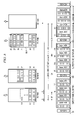
In FIG. 4, there is shown how the link latency (D) 402 for a wireless link in a wireless network such as a UWB system, using an MPEG2 application, is calculated in accordance with another embodiment of the invention. As shown, each data frame (e.g., 16) may include up to 12 MPEG2 packets. Each superframe in time line, for example, superframe 410, includes 4 transmit opportunities (17-20) each good for transmitting a data frame and an immediate acknowledgment. In the example of FIG. 4, the CTA shown in time line 408 comports to the Institute of Electrical and Electronic Engineers (IEEE) 802.15.3 standard or other appropriate medium access control (MAC) specifications. The link latency 402 is shown as the sum of intervals D1, D2 and D3. Interval D1 is the maximum time between the arrival of the first MPEG2 packet of the latest data frame in the TX RAM 304 and the start of the next transmission opportunity for this MPEG2 stream. D2 is equal to the time between the start of the earliest transmission opportunity for the MPEG2 stream, after the arrival of the first MPEG2 cell of the latest frame, and the end of the successful transmission of the frame. While D3 is the time between the end of the successful transmission of the frame and its release out of the RX RAM 406′.
Time line 408 shows the transmission of the different data frames and the Immediate Acknowledgments (Imm-ACK) that are sent out as soon as a particular frame (e.g., 17) is received. FIG. 4 also shows the TX RAM 404 and RX RAM 406 at different points in time, which are labeled 404′ and 406′ respectively.
In FIG. 5, there is shown how the UWB link latency D is equal to or greater than (≧) the maximum time interval spanning one frame transmission and its target retries plus the number of frame transmissions the failed frame must wait before its turn for transmission since its arrival in the TX RAM. In the example shown in FIG. 5, I is equal to 9, since there are only 9 transmission opportunities (i.e., 9 data frames may be transmitted) during the UWB link latency time.
In FIG. 6, there is shown how the TX RAM size is determined in accordance with an embodiment of the invention. Ideally, the TX RAM 602 should have TX RAM size be equal to or greater than (≧) 1 data frame+maximum number of data frames that may be transmitted during the UWB link latency time interval (D). In this example, that would be (1+9) data frames (frames 56-65) which could transmitted during the UWB link latency time interval (D), so the TX RAM 602 should be large enough in order to accommodate 10 or more data frames in order to avoid overflow conditions. Another consideration to look at when determining the TX RAM size is to have the TX RAM size be equal to or greater (≧) than the maximum number of data frames that may arrive in the TX RAM 602 during the UWB link latency time period (D.) This approach looks at the applications characteristics, in this particular illustrative example, the speed at which the MPEG2 application loads the TX RAM. The TX RAM should have at least the larger size obtained from the two approaches in order to be applicable to either scenario.
FIG. 7 shows an illustration on how to calculate the RX RAM size in accordance with an embodiment of the invention. In this embodiment, the RX RAM size should be ≧maximum number of data frames that may be transmitted during a time interval of D, so that the RX RAM will not have an overflow while a data frame is still held in it waiting for its release time. The RX RAM size can also be determined by RX RAM size ≧maximum number of data frames that may arrive in the TX RAM during a time interval D. Again, the RX RAM should have at least the larger size inferred from both considerations.
In FIG. 8, there is shown some illustrations of retries of frames 17 and 19 which may be due to noise, interference or other factors. Some considerations for the amount of retries that should be allowed include the fact that retries, even when within the target retry limit, may result in transmission of aged MPEG2 packets and cause an overflow of the TX RAM as shown by TX RAM 802. The TX RAM overflow was caused by excessive retries within time period D occurred as shown. Another consideration for retries is that retries, without appropriate control, may lead to the transfer of MPEG2 packets after, but not before, their buffering time at the TX RAM exceeded the link latency period, when the CTA net throughput pertaining to the stream is close to the stream arrival data rate.
In an MPEG2 streaming video example, where 1 MPEG2 packet or cell is 188 bytes+a 4 byte timestamp for a total of 192 bytes, 1 data frame=12 MPEG2 cells; 1 Channel Time Allocation (CTA)=4 data frames; 1 Superframe=3 CTAs; 1 video stream=1 CTA (per Superframe); and the Superframe duration (SF)=2,680 μs; CTA duration=940 μs; MCTA duration=70 μs; using a Guard Time (GT)=2 μs; and using an MPEG2 application where 1 cell=188B from MPEG2 TS+4B for UWB timestamp; the MPEG2 cell data rate=19.404 MB/s=45, 478,125 cells/hour=3,789,844 frames/hour; and the Physical Layer (PHY) rate=110 Mb/s:
Using a wireless transmission range of 7.3 meter (m) the following was achieved,
    • FER (frame payload=1,024 bytes)=1%;
    • FER (frame payload=12 MPEG2 cells+8B IC+4B FCS)=2.26%;
    • FLR (retry limit per frame=3)=2.62E-7, i.e., 1 frame/hour; and
    • Net throughput per CTA=26.9 Mb/S, accounting for retires; and
using a wireless transmission range of 9.0 m the following was achieved,
    • FER (frame payload=1,024 bytes)=10%;
    • FER (frame payload=12 MPEG2 cells+8B IC+4B FCS)=22.62%;
    • FLR (retry limit per frame=9)=3.50E-7 1.33 frames/hour; and
    • Net throughput per CTA=21.3 Mb/s—accounting for retries.
In FIG. 9, there is shown the link latency for the UWB system having a range of 7.3 meters (m). In this example, D1 is equal to the framing delay, which is equal to 1000 microseconds (μs). Up to F=12 MPEG2 cells across a time interval up to D=1,000 μs are assembled into a data frame in the TX RAM. Frame assembling stops whenever either limit, F=12 MPEG2 cells or D1=1,000 μs is reached. D2 in this example is equal to 2,680 μs+182 μs or 2,862 μs which is the maximum time interval spanning one transmission and 3 retries. D3 is equal to 40 μs which is the minimum time between the end of a received data frame and the release of the earlier MPEG2 cell in that data frame. The UWB link latency in this example is therefore equal to 1,000 μs+2,862 μs+40 μs=3,902 μs.
Referring now to FIG. 10, there is shown an illustrative example on how to determine the TX RAM size for a range of 7.3 meters for the UWB system. The TX RAM size should be ≧1 data frame+maximum number of data frames that may be transmitted during a time interval of D which as discussed before in this example is equal to 3,902 μs. In this illustrative example, this is equal to (1+7) data frames=8×2,320 bytes=18,560 bytes, assuming 1 data frame=(16+12×192) bytes=2,320 bytes. A second criteria to look at for the TX RAM size is that the TX RAM size should be ≧maximum number of data frames that may arrive in the TX RAM during a time interval of D which is equal to 3,902 μs, which is equal to 19,404×3,902/8 bytes (unframed)=┌9,464/(192×12)┐×2,320 bytes=11,600 bytes. So taking the two criteria discussed, to be safe, the TX RAM should have a size of at least 11,600 bytes given the speed in which the MPEG2 application delivers frames into the TX RAM buffer.
In FIG. 11, there is shown an illustrative example on how the RX RAM size is determined for a UWB range of 7.3 meters. In accordance with an embodiment of the invention, the RX RAM size should be ≧the maximum number of data frames that may be transmitted during a time interval of D=3,902 μs=4 data frames=4×2,320 bytes=9,280 bytes, assuming 1 data frame=(16+12×192) bytes=2,320 bytes. In the second consideration or application related consideration for the RX RAM size, the RX RAM size should be ≧the maximum number of data frames that may arrive in the TX RAM during a time interval of D=3,902 μs=19,404×3,902/8 bytes (unframed)=9,464 bytes (unframed)=[9,464/(192×12)]×2,320 bytes=11,600 bytes. Thus, in order to avoid buffer overflows, the RX RAM should be at least 11, 600 bytes given the speed in which the MPEG2 application loads the TX RAM.
In FIG. 12, there is shown an illustrative example highlighting some of the transmission constraints for an UWB system with a range equal to 7.3 meters. In the illustrative example shown, a data frame must be transmitted within I=4 frame transmissions (frame numbers 16-19) since the arrival of its earliest MPEG2 cell in order to meet the UWB link latency of D=3,902 μs.
In summary, using the retry algorithm of the present invention in an UWB system that transfers MPEG2 streaming video, where 1 data frame=12 192-byte MPEG2 cells (188 bytes for standard MPEG2 cell and 4 bytes for UWB timestamp)+16-byte MAC/PHY header=2,320 bytes; the MPEG2 cell data rate=19.404 Mb/s=45,478,125 cells/hour=3,789,844 frames/hour; the PHY rate=110 Mb/s; and the Data frame delay lime=1,000 μs; the following results were had using the retry algorithm of the invention:
For a Wireless Range Between the Two Wireless Devices Equal to 7.3 Meters:
    • Net throughput per CTA=26.9 Mb/s
    • Retry limit=3, target frame loss rate=1 frame/hour
    • UWB link latency=3,902 μs
    • TX RAM size=8 data frames=18,560 bytes=18.1 KB
    • RX RAM size=4 data frames=9,280 bytes=9.1 KB
      For a Wireless Range Between the Two Wireless Device Equal to 9.0 Meters:
    • Net throughput per CTA=21.3 Mb/s
    • Retry limit=9, target frame loss rate=1.33 frames/hour
    • UWB link latency=8,268 μs
    • TX RAM size=14 data frames=32,480 bytes=31.7 KB
    • RX RAM size=12 data frames=27,840 bytes=27.2 KB
Without retries, the frame loss rate is too large, while with too many retries, the link latency increases, the TX RAM overflows and the RX RAM under-runs. Different degrees of retries accommodate different ranges of frame error rates and achieve different ranges of frame loss rates. While different degrees of retries require different transmission link latencies and different TX and RX RAM sizes, the retry algorithm of the invention takes into account these different competing concerns and provides a straightforward solution on how many retries should be used given the different system conditions. The retry algorithm tries to achieve a constant delay for each packet in a frame like those used in an MPEG-2 application. The other advantage of the invention is that “old” packets can be dropped at the transmitter side, thereby clearing up the channel congestion caused by retries. The invention addresses the unique characteristics (e.g., high error rates and bursty transmissions) of wireless networks and the stringent timing and frame loss rate requirements and variable data rates encountered with Audio/Video applications such as MPEG-2.
While the preferred embodiments of the invention have been illustrated and described, it will be clear that the invention is not so limited. Numerous modifications, changes, variations, substitutions and equivalents will occur to those skilled in the art without departing from the spirit and scope of the present invention as defined by the appended claims.

Claims (22)

1. A method for determining the transmission and retransmission attempts that will be made for a frame that needs to be transmitted, comprising:
assembling the frame at a transmit buffer;
storing the frame at the transmit buffer; and
determining a value of N based on the equation N=min (N+B, I+1−Q) for a new transmission attempt and N=N−1 for a retransmission attempt to determine a maximum number of transmission and retransmission attempts that may be made to transmit or retransmit the frame, the equation recalculates a value of N, based on the previous value N, wherein:
N, after the recalculation, specifies a maximum number of transmission and retransmission attempts that may be made for a frame in the head of a transmit queue; B specifies a number of transmit opportunities elapsed between the arrivals of two successive frames in the transmit queue; Q specifies a number of frames currently residing in the transmit queue; and I specifies a constant value equal to a maximum number of transmit opportunities for a frame.
2. A method as defined in claim 1, wherein the value for the parameter I is set prior to transmitting the first frame of the transmit queue and remains unchanged for transmitting the subsequent frames of the transmit queue.
3. A method as defined in claim 1, wherein the value for the parameter I is related to the available bandwidth allocated for transmitting the frames in the transmit queue.
4. A method as defined in claim 3, wherein the value for I is also dependent on a size of the transmit buffer.
5. A method as defined in 1, further comprising:
setting both B and N equal to I when the transmit buffer is empty.
6. A method as defined in claim 5, wherein the recalculated value of N is determined prior to each transmission or retransmission.
7. A method as defined in claim 6, wherein the frame is transmitted or retransmitted if the recalculated value of N is greater than 0.
8. A method as defined in claim 6, wherein the frame is discarded if the recalculated value of N equals zero.
9. A communication device, including a transmit buffer for storing a frame that needs to be transmitted, the communication device comprising:
a transmit buffer for storing a frame that needs to be transmitted; and
means for recalculating a value of N based on the previous value of N using the equation N=min (N+B, I+1−Q) for a new transmission attempt and N=N−1 for a retransmission attempt to determine a number of transmission and retransmission attempts that may be made to transmit or retransmit the frame, wherein:
N, after the recalculation, specifies a maximum number of transmission and retransmission attempts that may be made for a frame in the head of a transmit queue; B specifies a number of transmit opportunities elapsed between the arrivals of two successive frames in the transmit queue; Q specifies a number of frames currently residing in the transmit queue; and I specifies a constant value equal to a maximum number of transmit opportunities for a frame.
10. A communication device as defined in claim 9, wherein the communication device includes a transmit buffer or transmit queue coupled to packets generated from Moving Picture Experts Group 2 (MPEG-2) codec.
11. A communication device as defined in claim 9, wherein the means for recalculating the value of N based on the equation N =min (N+B, I+1−Q) for a new transmission attempt or N=N−1 for a retransmission attempt attempts to adapt the number of retries to incoming and outgoing data rate changes in order to provide a substantially fixed delay wireless link.
12. A communication device as defined in claim 11, wherein the value for I is equal to a maximum number of transmit opportunities for a frame.
13. A communication device as defined in claim 11, further comprising a receive buffer coupled to the frames that are received.
14. A communication device as defined in claim 11, is transmitted or retransmitted if the recalculated value of N is greater than 0.
15. A communication device as defined in claim 11, wherein the frame is discarded if the recalculated value of N is equal to zero.
16. A communication device as defined in claim 14, wherein the communication device comprises a set top box.
17. A communication device as defined in claim 14, wherein the recalculated value of N is maintained so that it is not larger than (I+1−−Q).
18. A method for maintaining a substantially constant delay for each packet in a frame that is transmitted between a first and a second communication device, comprising the steps of:
(a) recalculating a maximum number of transmission and retransmission attempts that may be made for every frame that is to be transmitted or retransmitted from the first to the second communication device; and
(b) using the equation to recalculate a value of N=min (N+B, I+1−Q) for a new transmission attempt and N=N−1 for a retransmission attempt in order to determine the maximum number in step (a), the equation recalculates a value of N, based on the previous value of N,
wherein N, after the recalculation, specifies a number of transmission and retransmission attempts that may be made for a frame in the head of a transmission queue to be transmitted from the first to the second communication device, B specifies a number of transmit opportunities elapsed between the arrivals of two successive frames in the transmit queue; Q specifies a number of frames currently residing in the transmit queue; and I specifies a constant value equal to a maximum number of transmit opportunities for a frame.
19. A method as defined in claim 18, wherein the value for I comprises a fixed number that is stored within the first communication device.
20. A method as defined in claim 18, wherein steps (a) and (b) are performed prior to every transmission or retransmission between the first and second communication devices.
21. A method for recalculating a maximum number of transmission and retransmission attempts that may be made for a frame in the head of a transmit queue that needs to be transmitted from a first wireless communication device to a second wireless communication device using a communication link, the method comprising:
(a) assembling and storing the frame at a transmit queue or transmit buffer located in the first wireless communication device;
(b) determining a link delay for the communication link;
(c) determining a maximum number of transmit opportunities that can be had for a frame to be transmitted by the first wireless communication device to the second communication device given the link delay between the two devices;
(d) determining the number of frames currently located in the transmit buffer; and
(e) using the previous number of transmission and retransmission attempts, the maximum number of transmit opportunities determined in (c) and the number of frames in the transmit buffer determined in (d) to recalculate the number of transmission and retransmission attempts that can be made for the frame.
22. A method as defined in claim 21, further comprising:
determining the number of transmit opportunities elapsed between the arrivals of two successive frames in the transmit buffer.
US10/890,679 2004-02-09 2004-07-14 Method and apparatus for providing retry control, buffer sizing and management Active 2026-07-18 US7355976B2 (en)

Priority Applications (1)

Application Number Priority Date Filing Date Title
US10/890,679 US7355976B2 (en) 2004-02-09 2004-07-14 Method and apparatus for providing retry control, buffer sizing and management

Applications Claiming Priority (2)

Application Number Priority Date Filing Date Title
US54333804P 2004-02-09 2004-02-09
US10/890,679 US7355976B2 (en) 2004-02-09 2004-07-14 Method and apparatus for providing retry control, buffer sizing and management

Publications (2)

Publication Number Publication Date
US20050175024A1 US20050175024A1 (en) 2005-08-11
US7355976B2 true US7355976B2 (en) 2008-04-08

Family

ID=34830585

Family Applications (1)

Application Number Title Priority Date Filing Date
US10/890,679 Active 2026-07-18 US7355976B2 (en) 2004-02-09 2004-07-14 Method and apparatus for providing retry control, buffer sizing and management

Country Status (1)

Country Link
US (1) US7355976B2 (en)

Cited By (10)

* Cited by examiner, † Cited by third party
Publication number Priority date Publication date Assignee Title
US20070002827A1 (en) * 2005-06-30 2007-01-04 Victor Lau Automated serial protocol target port transport layer retry mechanism
US20070011333A1 (en) * 2005-06-30 2007-01-11 Victor Lau Automated serial protocol initiator port transport layer retry mechanism
US20070058635A1 (en) * 2005-08-05 2007-03-15 Sony Corporation And Sony Electronics, Inc. Systems and methods for transmitting data over lossy networks
US20070198898A1 (en) * 2006-02-07 2007-08-23 Alcatel Lucent Device and method for mitigating effects of impulse noise on data packet transfer
US20070240191A1 (en) * 2006-03-24 2007-10-11 Samsung Electronics Co., Ltd. Method and system for transmission of uncompressed video over wireless communication channels
US20070245387A1 (en) * 2006-03-29 2007-10-18 Samsung Electronics Co., Ltd. Method and system for video stream transmission over wireless channels
US20080141091A1 (en) * 2006-12-06 2008-06-12 General Instrument Corporation Method and Apparatus for Recovering From Errors in Transmission of Encoded Video Over a Local Area Network
US20090016445A1 (en) * 2007-07-10 2009-01-15 Qualcomm Incorporated Early rendering for fast channel switching
US7881275B1 (en) 2005-08-12 2011-02-01 Marvell International Ltd. Rate adaptation
US8451910B1 (en) * 2006-07-13 2013-05-28 Logitech Europe S.A. Wireless multimedia device with real time adjustment of packet retry function and bit rate modulation

Families Citing this family (8)

* Cited by examiner, † Cited by third party
Publication number Priority date Publication date Assignee Title
US20070234170A1 (en) * 2006-03-29 2007-10-04 Samsung Electronics Co., Ltd. Method and system for communication of video information over wireless channels
US8184556B2 (en) * 2007-11-19 2012-05-22 Ciena Corporation Systems and methods for distance-proof N-pass auto negotiation for gigabit ethernet
US8205126B2 (en) 2007-11-27 2012-06-19 Samsung Electronics Co., Ltd. System and method for wireless communication of uncompressed video using selective retransmission
US20090303871A1 (en) * 2008-06-10 2009-12-10 Electronics Telecommunications Research Institute Method and apparatus for packet aggregation according to traffic characteristics
JP2009302929A (en) * 2008-06-13 2009-12-24 Sony Corp Receiver, installation situation notification method and transmission/reception system
US8045471B2 (en) * 2008-06-30 2011-10-25 Siemens Enterprise Communications Gmbh & Co. Kg Method and apparatus to inspect wireless traffic and mitigate packet elimination for wireless saturation avoidance
US9660919B2 (en) * 2013-01-28 2017-05-23 Apple Inc. Adaptive data connection retry by a wireless communication device
US20220179579A1 (en) * 2020-12-08 2022-06-09 EXFO Solutions SAS Monitoring performance of remote distributed storage

Citations (10)

* Cited by examiner, † Cited by third party
Publication number Priority date Publication date Assignee Title
US4912703A (en) * 1987-09-30 1990-03-27 Kabushiki Kaisha Toshiba Apparatus and method for data flow control in broadcast data transmission system
US20020073184A1 (en) * 2000-10-10 2002-06-13 Satoru Maeda Terminal apparatus setting method
US20020099838A1 (en) * 2001-01-22 2002-07-25 Donia Sebastian Method for allocating receive buffers to accommodate retransmission scheme in wireless computer networks
US20030214955A1 (en) * 2002-05-14 2003-11-20 Samsung Electronics Co., Ltd. Apparatus and method for offering connections between network devices located in different home networks
US20040105444A1 (en) * 2002-11-15 2004-06-03 Korotin Dmitry O. Auto-configuration of broadband service for one of a plurality of network communication protocols
US20040132452A1 (en) * 2002-12-30 2004-07-08 Dong-Hee Lee Apparatus and method for establishing a session in a radio network organized with mobile nodes
US20040136331A1 (en) * 2000-10-11 2004-07-15 Aperto Networks, Inc. Automatic retransmission and error recovery for packet oriented point-to-multipoint communication
US20040165595A1 (en) * 2003-02-25 2004-08-26 At&T Corp. Discovery and integrity testing method in an ethernet domain
US6795443B1 (en) * 1998-11-10 2004-09-21 Korea Telecommunication Authority Apparatus and method of providing internet protocol (IP) level connectivity between internet access terminals using service gateway
US6986158B1 (en) * 1999-03-18 2006-01-10 Fujitsu Limited System and method for distributing video information over network

Patent Citations (10)

* Cited by examiner, † Cited by third party
Publication number Priority date Publication date Assignee Title
US4912703A (en) * 1987-09-30 1990-03-27 Kabushiki Kaisha Toshiba Apparatus and method for data flow control in broadcast data transmission system
US6795443B1 (en) * 1998-11-10 2004-09-21 Korea Telecommunication Authority Apparatus and method of providing internet protocol (IP) level connectivity between internet access terminals using service gateway
US6986158B1 (en) * 1999-03-18 2006-01-10 Fujitsu Limited System and method for distributing video information over network
US20020073184A1 (en) * 2000-10-10 2002-06-13 Satoru Maeda Terminal apparatus setting method
US20040136331A1 (en) * 2000-10-11 2004-07-15 Aperto Networks, Inc. Automatic retransmission and error recovery for packet oriented point-to-multipoint communication
US20020099838A1 (en) * 2001-01-22 2002-07-25 Donia Sebastian Method for allocating receive buffers to accommodate retransmission scheme in wireless computer networks
US20030214955A1 (en) * 2002-05-14 2003-11-20 Samsung Electronics Co., Ltd. Apparatus and method for offering connections between network devices located in different home networks
US20040105444A1 (en) * 2002-11-15 2004-06-03 Korotin Dmitry O. Auto-configuration of broadband service for one of a plurality of network communication protocols
US20040132452A1 (en) * 2002-12-30 2004-07-08 Dong-Hee Lee Apparatus and method for establishing a session in a radio network organized with mobile nodes
US20040165595A1 (en) * 2003-02-25 2004-08-26 At&T Corp. Discovery and integrity testing method in an ethernet domain

Cited By (20)

* Cited by examiner, † Cited by third party
Publication number Priority date Publication date Assignee Title
US20070002827A1 (en) * 2005-06-30 2007-01-04 Victor Lau Automated serial protocol target port transport layer retry mechanism
US20070011333A1 (en) * 2005-06-30 2007-01-11 Victor Lau Automated serial protocol initiator port transport layer retry mechanism
US20100211843A1 (en) * 2005-08-05 2010-08-19 Sony Corporation Systems and methods for transmitting data over lossy networks
US20070058635A1 (en) * 2005-08-05 2007-03-15 Sony Corporation And Sony Electronics, Inc. Systems and methods for transmitting data over lossy networks
USRE46167E1 (en) * 2005-08-05 2016-09-27 Sony Coporation Systems and methods for transmitting data over lossy networks
US7747921B2 (en) * 2005-08-05 2010-06-29 Sony Corporation Systems and methods for transmitting data over lossy networks
US8429476B2 (en) * 2005-08-05 2013-04-23 Sony Corporation Systems and methods for transmitting data over lossy networks
US8787405B1 (en) * 2005-08-12 2014-07-22 Marvell International Ltd. Device and method for adapting transmission parameters based on successful transmission of a frame
US7881275B1 (en) 2005-08-12 2011-02-01 Marvell International Ltd. Rate adaptation
US8295259B1 (en) 2005-08-12 2012-10-23 Marvell International Ltd. Rate adaptation
US20070198898A1 (en) * 2006-02-07 2007-08-23 Alcatel Lucent Device and method for mitigating effects of impulse noise on data packet transfer
US9455800B2 (en) * 2006-02-07 2016-09-27 Alcatel Lucent Device and method for mitigating effects of impulse noise on data packet transfer
US20070240191A1 (en) * 2006-03-24 2007-10-11 Samsung Electronics Co., Ltd. Method and system for transmission of uncompressed video over wireless communication channels
US8363675B2 (en) 2006-03-24 2013-01-29 Samsung Electronics Co., Ltd. Method and system for transmission of uncompressed video over wireless communication channels
US20070245387A1 (en) * 2006-03-29 2007-10-18 Samsung Electronics Co., Ltd. Method and system for video stream transmission over wireless channels
US8432938B2 (en) 2006-03-29 2013-04-30 Samsung Electronics Co., Ltd. Method and system for video stream transmission over wireless channels
US8451910B1 (en) * 2006-07-13 2013-05-28 Logitech Europe S.A. Wireless multimedia device with real time adjustment of packet retry function and bit rate modulation
US20080141091A1 (en) * 2006-12-06 2008-06-12 General Instrument Corporation Method and Apparatus for Recovering From Errors in Transmission of Encoded Video Over a Local Area Network
US9426522B2 (en) * 2007-07-10 2016-08-23 Qualcomm Incorporated Early rendering for fast channel switching
US20090016445A1 (en) * 2007-07-10 2009-01-15 Qualcomm Incorporated Early rendering for fast channel switching

Also Published As

Publication number Publication date
US20050175024A1 (en) 2005-08-11

Similar Documents

Publication Publication Date Title
US7355976B2 (en) Method and apparatus for providing retry control, buffer sizing and management
US7944819B2 (en) System and method for transmission and acknowledgment of blocks of data frames in distributed wireless networks
US7274691B2 (en) Network switch with packet scheduling
JP5095751B2 (en) Adaptive time allocation in TDMAMAC layer
EP1228595B1 (en) Method and system for discarding and regenerating acknowledgment packets in adsl communications
EP2103054B1 (en) Signature sequences and methods for time-frequency selective channel
US7707303B2 (en) Method and devices for controlling retransmissions in data streaming
US6937600B2 (en) Communication device and communication control method using lower layer data transmission order control at upper layer
JP2010522468A (en) Throughput improvement in LAN by managing TCPACK
US8072886B2 (en) Method and system for transmission control protocol (TCP) traffic smoothing
US10439940B2 (en) Latency correction between transport layer host and deterministic interface circuit
JP2006511140A (en) Real-time data protection in wireless networks
EP2380294B1 (en) Method for controlling a flow in a packet switching network
WO2003065661A9 (en) Method and system of data packet transmission timing for controlling bandwidth
US8139600B1 (en) Quality of service half-duplex media access controller
US20050122904A1 (en) Preventative congestion control for application support
CN111194056B (en) Encapsulation of data packets
JP2013013093A (en) Improving throughput in lan by managing tcp acks
JP3454998B2 (en) Communications system
KR20140110890A (en) A network gateway and a method for transmitting packets of a data stream
JP3299225B2 (en) Transmission apparatus and method for communication system
EP1950928B1 (en) Apparatus and method for real-time packet reception
Ohtani et al. Implementation of wireless MPEG2 transmission system using IEEE 802.11 b PHY
Peart et al. Improved quality of service utilising high priority traffic in HCF in a dynamically changing wireless networks

Legal Events

Date Code Title Description
AS Assignment

Owner name: TEXAS INSTRUMENTS INCORPORATED, TEXAS

Free format text: ASSIGNMENT OF ASSIGNORS INTEREST;ASSIGNORS:HO, JIN-MENG;ERICKSON, JOSEPH MICHAEL;TAI, HORNG-MING LOBO;REEL/FRAME:015579/0561

Effective date: 20040708

STCF Information on status: patent grant

Free format text: PATENTED CASE

FPAY Fee payment

Year of fee payment: 4

FPAY Fee payment

Year of fee payment: 8

MAFP Maintenance fee payment

Free format text: PAYMENT OF MAINTENANCE FEE, 12TH YEAR, LARGE ENTITY (ORIGINAL EVENT CODE: M1553); ENTITY STATUS OF PATENT OWNER: LARGE ENTITY

Year of fee payment: 12