US7346131B2 - System and method for pre-FFT OFDM fine synchronization - Google Patents
System and method for pre-FFT OFDM fine synchronization Download PDFInfo
- Publication number
- US7346131B2 US7346131B2 US10/193,102 US19310202A US7346131B2 US 7346131 B2 US7346131 B2 US 7346131B2 US 19310202 A US19310202 A US 19310202A US 7346131 B2 US7346131 B2 US 7346131B2
- Authority
- US
- United States
- Prior art keywords
- sum
- product shift
- received signal
- signal
- calculating
- Prior art date
- Legal status (The legal status is an assumption and is not a legal conclusion. Google has not performed a legal analysis and makes no representation as to the accuracy of the status listed.)
- Expired - Fee Related, expires
Links
Images


Classifications
-
- H—ELECTRICITY
- H04—ELECTRIC COMMUNICATION TECHNIQUE
- H04L—TRANSMISSION OF DIGITAL INFORMATION, e.g. TELEGRAPHIC COMMUNICATION
- H04L27/00—Modulated-carrier systems
- H04L27/26—Systems using multi-frequency codes
- H04L27/2601—Multicarrier modulation systems
- H04L27/2647—Arrangements specific to the receiver only
- H04L27/2655—Synchronisation arrangements
- H04L27/2662—Symbol synchronisation
-
- H—ELECTRICITY
- H04—ELECTRIC COMMUNICATION TECHNIQUE
- H04L—TRANSMISSION OF DIGITAL INFORMATION, e.g. TELEGRAPHIC COMMUNICATION
- H04L27/00—Modulated-carrier systems
- H04L27/26—Systems using multi-frequency codes
- H04L27/2601—Multicarrier modulation systems
- H04L27/2647—Arrangements specific to the receiver only
- H04L27/2655—Synchronisation arrangements
- H04L27/2657—Carrier synchronisation
-
- H—ELECTRICITY
- H04—ELECTRIC COMMUNICATION TECHNIQUE
- H04L—TRANSMISSION OF DIGITAL INFORMATION, e.g. TELEGRAPHIC COMMUNICATION
- H04L27/00—Modulated-carrier systems
- H04L27/26—Systems using multi-frequency codes
- H04L27/2601—Multicarrier modulation systems
- H04L27/2647—Arrangements specific to the receiver only
- H04L27/2655—Synchronisation arrangements
- H04L27/2668—Details of algorithms
- H04L27/2673—Details of algorithms characterised by synchronisation parameters
- H04L27/2675—Pilot or known symbols
Definitions
- the present invention relates generally to orthogonal frequency division multiplexing (OFDM) systems and receivers, and more particularly, to a pre-Fast Fourier Transform (FFT) fine synchronization in OFDM receivers.
- OFDM orthogonal frequency division multiplexing
- FFT pre-Fast Fourier Transform
- Patents 5,652,772 July 1997 Isaksson, et al. 5,771,224 June 1998 Seki et al 5,838,734 November 1998 Wright 5,867,532 February 1999 Ito et al. 5,920,598 July 1999 Hyakudai et al. 5,987,063 November 1999 Rinne 6,058,121 May 2000 Kim, et al. 6,137,847 October 2000 Stott, et al.
- orthogonal frequency division multiplexing OFDM
- the OFDM modulation systems are robust to multi-path interference.
- a transmitted signal includes a large number of subcarriers, reflective of the OFDM mode.
- the transmitted signal includes 1,705 subcarriers, while in the DVB-T 8k OFDM mode there are 6,817 subcarriers.
- the subcarriers are orthogonal to one another, and each is modulated with the digital data to be transmitted.
- orthogonality is a property of a set of functions such that the integral of the product of any two members of the set, taken over the appropriate interval, is zero. For example, trigonometric functions appearing in Fourier expansions are orthogonal functions.
- FIG. 1A an illustration of an OFDM frame structure is shown.
- the transmitted signal in an OFDM modulation system is organized in frames.
- Each frame includes a constant number of symbols.
- Each symbol is constructed from multiple subcarriers.
- FIG. 1B an illustration of a single symbol structure in the time domain is shown.
- a symbol includes two parts: a useful part ( 110 ) and guard interval part ( 120 ).
- the duration time (Ts) of the useful part is larger than that of the guard interval duration ( ⁇ ).
- a guard interval does not form an integral part of the data to be sent by the transmitter but is rather “artificially” prepended to the useful part during preparation of data for transmission.
- the guard is therefore redundant and is, as a rule, identified and removed at the receiver end.
- the subcarriers in a symbol are placed in certain constant frequency intervals, and are represented as a complex number each having a different frequency.
- a symbol is represented as the sum of subcarriers from subcarrier 0 to subcarrier N ⁇ 1.
- Each symbol includes (in its useful and guard parts) data subcarriers and pilot subcarriers (shown, schematically, in FIG. 1B ).
- pilots subcarriers are used for frame synchronization, time synchronization, frequency synchronization, and channel estimation. Additionally, pilots may be used for phase errors correction, as described, e.g. in “European Telecommunications Standards Institute (ETSI)—ETS 300 7444, “Digital Video Broadcasting (DVB); Framing structure, channel coding and modulation for digital Terrestrial television (DVB-T)”, March 1997.
- ETSI European Telecommunications Standards Institute
- DVB Digital Video Broadcasting
- Framing structure channel coding and modulation for digital Terrestrial television
- the pilots and the data sub-carriers are shown in the frequency domain in FIG. 1B as vertical arrow symbols (e.g. 130 and 140 ).
- Scattered pilots are spread equally in the symbol and between sets of symbols in a frame.
- scattered pilots are inserted at intervals of twelve subcarriers.
- Scattered pilots of a symbol are shifted, e.g. by three positions relative to the immediately preceding symbol. According to the equation there are four sets of scattered pilots.
- Symbols further include a constant number of continual pilots, which are placed at fixed locations in each symbol.
- the number of continual pilots and their positions depends on the OFDM mode.
- the TPS pilots are used for the purpose of signaling parameters related to the transmission scheme, which is the channel coding and modulation.
- the TPS pilots may convey the following information: OFDM transmission mode, the value of the guard interval, frame number, and so on.
- FIG. 2 where an exemplary block diagram of a hitherto known OFDM receiver 200 is shown (e.g., “Speth M., Fechtel S., Fock G. and Meyr H., “Optimum Receiver Design for OFDM-based Broadband Transmission—Part 2: A Case Study”, IEEE, Vol. 49, No.
- Receiver 200 is composed of the following units: analog front-end (AFE) 210 , demodulator 220 , guard removal unit 230 , pre-FFT estimation unit 240 , FFT unit 250 , equalizer 260 , and post-FFT estimation unit 270 .
- AFE analog front-end
- receiver 200 receives a modulated signal in the time domain, and transforms it to a demodulated signal in the frequency domain. The transformation is done using the fast Fourier transform (FFT) algorithm, and by means of FFT unit 250 .
- AFE 210 converts the received signal from analog form to digital form. Additionally AFE 210 converts the received signal frequency from radio frequency (RF) to intermediate frequency (IF).
- Demodulator 220 converts the received signal frequency from IF frequency to base-band frequency. Additionally, Demodulator 220 corrects the sampling clock offset and the carrier frequency offset according to the feedback from the estimation units.
- Guard removal unit 230 is used for removal of the guard-interval portion (e.g. 120 ) from the received symbol, as well as for timing synchronization.
- Timing synchronization is the task of locating the beginning of a received OFDM symbol.
- the timing synchronization ensures a synchronized operation of the transmitter (not shown) and the receiver.
- proper synchronization will facilitate display of qualitative images at the subscriber's screen on the basis of processing the useful parts of the symbols ( 110 in FIG. 1B ).
- the receiver fails to identify the beginning of the useful data part
- the inevitable result is that certain part of the (redundant) data guard ( 120 ) is processed (as it is erroneously identified by the receiver as belonging to the useful part of the symbol) and, obviously, degraded quality of images are obtained and displayed.
- a timing error is calculated, i.e. the time difference between transmission and receipt of the useful part for a given symbol.
- Post-FFT estimation unit 270 estimates the errors of timing synchronization, frequency synchronization, and sampling-clock synchronization, and performs channel estimation. Additionally, post-FFT estimation unit 270 provides a feedback to the relevant units with a correction signal. AFE 210 is provided with the sampling-clock error, demodulator 220 is provided with the frequency synchronization error, and guard removal 230 is provided with timing synchronization error. In order to provide a fast and reliable acquisition of information sent using OFDM, pre-FFT estimations are required. However, the pre-FTT estimations provide only coarse estimation for timing and frequency synchronizations. The coarse pre-FFT estimations are performed by pre-FFT estimation unit 240 . One of receiver 200 tasks is to recognize ghost symbols. A ghost symbol is the reflection of the transmitted signal on various obstacles found in a broadcast environment.
- CPE common phase error
- the invention provides for a synchronization unit for performing fine synchronization in the Time Domain, the synchronization unit comprises:
- a multiplier capable of calculating sum of zero product shift, sum of minus one product shift, and sum of plus one product shift, based on at least said reference signals
- the invention further provides for a method for estimating common phase error of a received signal, comprising:
- the invention provides for a method for estimating timing error of a received signal, comprising:
- the invention provides for a method for estimating a correlation level indicative of at least correlation between received signal and a ghost thereof, comprising:
- the invention provides for a synchronization unit for performing phase error synchronization in the time domain, the synchronization unit comprises:
- a storage for digitally storing at least a reference signal
- the invention further provides for a synchronization unit for performing timing synchronization in the time domain, the synchronization unit comprises:
- the invention provides for a synchronization unit for estimating the correlation level indicative of at least correlation between received signal and a ghost thereof, the synchronization unit comprises:
- a receiver that includes a synchronization unit for performing fine synchronization of a received signal, comprising:
- the invention provides for a receiver fitted in a digital television system for receiving a broadcast signal from a television transmitting system, comprising:
- FIG. 1 is a schematic illustration of OFDM frame structure
- FIG. 2 is an exemplary block diagram of OFDM receiver in accordance with the prior art
- FIG. 3 is an illustration of a symmetric waveform, in accordance with one embodiment of the invention.
- FIG. 4 is an exemplary block diagram of pre-FFT estimation unit, in accordance with an embodiment of the invention.
- FIG. 5 is a flow chart illustrating a multiplying procedure, in accordance with an embodiment of the invention.
- FIG. 6 is a flow chart illustrating the process of estimating the phase error, in accordance with an embodiment of the invention.
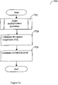
- FIG. 7 A is a flow chart illustrating the process of estimating the correlation level, in accordance with an embodiment of the invention.
- FIG. 7 B illustrates how to determine if a received symbol is synchronized with current scattered pilots set, in accordance with one embodiment of the invention
- FIG. 7C illustrates how to determine if a received symbol includes ghost component, in accordance with one embodiment of the invention.
- FIG. 8 is a flow chart illustrating the process of estimating the timing error, in accordance with an embodiment of the invention.
- the invention provides a system and method for performing accurate timing synchronization, filtering ghost signal through the calculation of correlation level, and detecting phase error in at least orthogonal frequency division multiplexing (OFDM) transmission.
- OFDM orthogonal frequency division multiplexing
- these activities are performed in the time domain, before executing the fast Fourier transform (FFT) algorithm.
- FFT fast Fourier transform
- a symmetric waveform 300
- An exemplary symmetric waveform i.e. SINC waveform represented also as sin(x)/x
- the symmetric characteristics of the signal can be used for estimating the sought timing errors phase errors, and correlation level. Note that certain aspects of the present invention concern scattered and continual pilots.
- FIG. 4 where there is shown a block diagram of a synchronization unit (SU) 400 for pre-FFT synchronization in accordance with one embodiment of the invention.
- the SU is incorporated in module 240 (discussed with reference to FIG. 2 ).
- the invention is not bound by this architecture and any implementation for estimating one or more of timing error, phase error and correlation level at time domain is embraced by the invention.
- SU 400 improves the hitherto known pre-FFT estimations, e.g. unit 240 , which is described in the prior art. Comparing, for example, to pre-FFT estimation unit 240 , SU 400 provides finer synchronization (due to accurate estimation of timing error) and common phase error (CPE) estimation. The latter has not been determined in the pre-FFT computations according to the prior art.
- pre-FFT estimation unit 240 Comparing, for example, to pre-FFT estimation unit 240 , SU 400 provides finer synchronization (due to accurate estimation of timing error) and common phase error (CPE) estimation. The latter has not been determined in the pre-FFT computations according to the prior art.
- CPE common phase error
- SU 400 is composed of reference memory 410 , multiplier 420 , signal analyzer 430 , timing estimation unit 440 , phase estimation unit 450 , and correlation-level estimation unit 460 .
- SU 400 obtains a demodulated OFDM signal through line 470 (delivered, by this embodiment from module 230 of FIG. 2 ), and produces signal estimations of timing error, phase error, and calculation of correlation level.
- the correlation level includes information about the correlation between the data in the received symbol and the reference signals.
- the correlation level is further processed (as discussed in detail below) mainly for enabling synchronization to the current scattered set and for identifying and eliminating ghosts from the symbol.
- Reference memory 410 is pre-loaded with reference signals, typically pilot reference signals (hereinafter “PRS”), which by this embodiment are the inverse fast Fourier transform (IFFT) of the pilots.
- PRS pilot reference signals
- the reference signals may be the IFFT of the scattered pilots, continual pilots, or the sum of the scattered pilots and the continual pilots.
- Reference memory 410 may be, read only memory (ROM), erasable programmable read only memory (EPROM), Flash memory, or any other type of read only memory. It is further possible to use volatile memory for this purpose provided that such memory is loaded at initialization with the PRS.
- multiplier 420 performs a complex number multiplication between a reference signal obtained from reference memory 410 and a demodulated OFDM symbol.
- the multiplication procedure is further detailed below.
- signal analyzer 430 calculates three points of the cross-correlation square magnitude, based on the signal coming from multiplier 420 . As can be seen in FIG. 3 , the three points are identified: center 310 , right 320 , and left 330 . If the center point of the received signal is found to be where center point 310 is shown then the system is synchronized with the current scattered set.
- timing synchronization error is estimated based on the position of the right and left cross-correlation points of the received signal as compared to the respective right 320 and left 330 .
- the timing synchronization error is proportional to the difference between the left 330 and right 320 points.
- the timing synchronization is calculated by timing estimation unit 440 .
- phase estimation unit 450 estimates the phase error signal.
- Phase error signal is obtained from angle of the complex number representation of the center point.
- correlation-level estimation unit 460 computes the correlation level signal of the transmitted symbol.
- the correlation level signal is used to synchronize the received symbol to the current scattered set. Further the correlation level may be used to determine if the receiver is synchronized to a real symbol, or to a ghost symbol.
- the invention is not bound by either the system architecture of FIG. 4 or by its functionality.
- only one (or two) of the specified timing error, phase error and correlation level value are calculated, all as required and appropriate, depending upon the particular application.
- multiplier 420 multiplies between PRS and a sample of the received signal y in (t j ).
- multiplier 420 multiplies in parallel three PRS signals with a corresponding y in (t j ) sample, i.e., PRS(j)* y in (t j ), PRS(j ⁇ 1)* y in (t j ), and PRS(j+1)*y in (t j ).
- step 510 the variable “j”, as well as the summation variables S 0 , S 1 , and S +1 are all set to zero.
- multiplier 420 obtains PRS(j ⁇ 1), PRS(j), and PRS(j+1) signals respectively from reference memory 410 .
- multiplier 420 multiplies each of PRS(j ⁇ 1 ), PRS(j) and PRS(j+1) with y in (t j ). A complex product between two complex numbers results in a complex number.
- multiplier 420 adds the product of y in (t j )*PRS(j ⁇ 1) to the previous sum of calculated products.
- multiplier 420 adds the product of y in (t j )*PRS(j) to the previous sum of calculated products.
- multiplier 420 adds the product of y in (t j )*PRS(j+1) to the previous sum of calculated products.
- multiplier 420 checks if the current index, i.e., “j”, equals “N ⁇ 1”. In the case where the current index “j” is not equal to “N ⁇ 1” then, “j” is increased by one in step 560 and the procedure is repeated for the newly updated “j”. In the case where “j” equals “N ⁇ 1” then, in step 570 procedure 500 returns the sums S 0 , S 1 , and S ⁇ 1 .
- S 0 , S 1 , and S ⁇ 1 correspond to zero, plus one, and minus one product shifts.
- multiplier 420 multiplies between y in (t j ) and PRS(j+1) by obtaining a PRS signal identical to PRS(j+1). This ability (i.e. selecting identical PRSs) is a based on the pilots' characteristic as discussed above.
- the invention is not bound by using a multiplier and in the case that a multiplier is used the invention is not bound by using the multiplier described above with reference to FIG. 5 .
- the multiplications are performed by multiplying each of y in (t j ), y in (t j ⁇ 1 ), and y in (t j+1 ) with PRS(j).
- multiplier may be realized in software, hardware or combination thereof, all as required and appropriate.
- multiplier 420 computes the values of the zero, plus one, and minus one product shifts, all as described above with reference to FIG. 5 . Each product shift results in a complex number, which includes an imaginary component and a real component.
- signal analyzer 430 passes the value of the zero product shift, i.e., S 0 , to phase estimation error unit 450 .
- phase estimation unit 450 computes the CPE.
- the CPE is equal to the angle of the complex number represented by S 0 (and obtained e.g., by applying tan ⁇ 1 between the complex number components, or—as will be exemplified below, by obtaining the angle of the complex number if it is represented using Euler equations. Note that extraction of the value of the angle from a complex number is well known in the art).
- phase error signal is sent to, say, a known per se phase controller that is used to eliminate the CPE.
- FIG. 7A showing one embodiment of flowchart 700 for computing the correlation level.
- the correlation level after being subject to further processing (as will be described in greater detail below) enables to determine, inter alia if the receiver is synchronized to the current scattered pilots set, and if the receiver is synchronized to an actual symbol. This will enable to determine whether the received symbol includes a ghost component and, if in the affirmative, enabling removal thereof.
- multiplier 420 computes the values of the zero, plus one, and minus one product shifts, all as described above with reference to FIG. 5 .
- each product shift value results in a complex number that includes an imaginary component and a real component.
- signal analyzer 430 calculates a single cross-correlation point, central 310 , for each received symbol.
- Point 310 is the square magnitude of the zero S 0 product shift calculated, e.g. by multiplier 420 described above.
- correlation-level estimation unit 460 obtains the central point's value from the signal analyzer 430 , and computes the correlation level. Correlation-level estimation unit 460 computes the correlation level by calculating the magnitude value of central point 310 .
- FIG. 7B showing one embodiment of flowchart 740 used for determining whether received symbols are synchronized to the current scattered pilots set. The determination is done based on the correlation level signal and by means of correlation-level estimation 460 .
- the scattered pilots are spread equally in the symbol and between sets in frame.
- a symbol is considered correlated if its scattered pilots set is as expected by OFDM receiver 200 .
- the scattered pilots include information essential for the symbol processing. Hence, receiver 200 must be synchronized with the corresponding scattered set.
- the correlation level is computed using the process described above.
- the correlation level is compared with the value of the expected center point 310 .
- a correlation error indication is generated.
- the correlation error indication is sent to a timing controller located, e.g. in guard removal 230 .
- the original central point 310 is compared to the shifted point located, for example, at point 340 .
- Correlation-level estimation unit 460 compares this value to the expected value of central point 310 (normally, between 0.7 to 1.3). If the square magnitude value is lower than the value of central point 310 , then SU 400 produces a correlation error indication.
- the correlation error indication is sent to a timing controller located, e.g. in guard-removal 230 .
- the timing controller based on the error indication, tries to synchronize the received symbol to current scattered pilots set, e.g., by changing the sampling rate.
- FIG. 7C showing one embodiment of flowchart 750 used for determining whether received symbols are synchronized with the actual signal, i.e. whether the received symbol is a ghost symbol or includes a ghost component.
- the determination is based on the correlation level.
- the correlation level signal is computed using the process described above.
- the value of a plus two-product shift is computed, i.e. computing the product of PRS(j)* y in (t j+2 ) for j starting from zero and ending at N ⁇ 1.
- the value of the plus two-product shift is computed by means of multiplier 420 .
- signal analyzer calculates the square magnitude of the plus two-product shift.
- step 754 the value of the square magnitude is compared with the correlation level computed in step 751 . If the comparison result indicates equality between both signals, then in step 755 , correlation-level estimation unit 460 generates a ghost error indication.
- the ghost error indication indicates that the received symbol is a ghost symbol or includes a ghost component. This indication instructs receiver 200 to disregard the received symbol.
- the received symbol dose not include ghost component, since the square magnitude of S + 2 (i.e. 2.25) is not equal to the value of the correlation level (i.e. 6.25). Had the square magnitude being equal or substantially equal to 6.25 it would have suggested that there is a ghost component that needs to be removed.
- multiplier 420 computes the values of the zero, plus one, and minus one product shifts (S 0 , S 1 and S ⁇ 1 , respectively). If these values are already available from previous calculations (e.g. from the correlation level and/or phase error estimations discussed above), the need to calculate them again is of course obviated. Each product shift value results in a complex number, which includes an imaginary component and a real component.
- signal analyzer 430 calculates two cross-correlation points, right 320 , and left 330 , for each symbol. The right point 320 and left point 330 are respectively the square magnitude of plus one S 1 , and minus one S ⁇ 1 product shifts.
- timing estimation unit 450 estimates the timing error.
- Timing estimation unit 450 computes the estimated timing error by calculating the difference between the magnitudes of points 350 and 360 .
- Timing estimation unit 440 computes the difference between these two values, which results in the timing error.
- the timing error is sent to a timing controller in guard-removal 230 .
- the timing controller using the timing error, tries to synchronize to the beginning of the received symbol, for example, by changing the sampling rate.
- a lower value of timing error indicates that guard removal 230 is synchronized to the beginning of the received signal, namely, guard removal 230 removes only guard interval 120 from the received symbol.
- phase error, timing error and correlation level are not necessarily implemented in any particular order and if desired they may be performed partially or wholly in parallel. As explained above, in certain embodiments, not all the specified values (time error, phase error and correlation level) are required.
- system may be a suitably programmed computer.
- the invention contemplates a computer program being readable by a computer for executing the method of the invention.
- the invention further contemplates a machine-readable memory tangibly embodying a program of instructions executable by the machine for executing the method of the invention.
Abstract
Description
| Patents | ||
| 5,652,772 | July 1997 | Isaksson, et al. | ||
| 5,771,224 | June 1998 | Seki et al | ||
| 5,838,734 | November 1998 | Wright | ||
| 5,867,532 | February 1999 | Ito et al. | ||
| 5,920,598 | July 1999 | Hyakudai et al. | ||
| 5,987,063 | November 1999 | Rinne | ||
| 6,058,121 | May 2000 | Kim, et al. | ||
| 6,137,847 | October 2000 | Stott, et al. | ||
- Speth M., Fechtel S., Fock G. and Meyr H., “Optimum Receiver Design for OFDM-based Broadband Transmission—Part 2: A Case Study”, IEEE, Vol. 49, No. 4, April 2001.
- European Telecommunications Standards Institute (ETSI—ETS 300 744, “Digital Video Broadcasting (DVB); Framing structure, channel coding and modulation for digital Terrestrial television (DVB-T)”, March 1997.
- Richard Van Nee and Ramjee Prasad, 2000, Artech House Publishers, ODFM for wireless multimedia communications.
- a signal analyzer capable of computing left, center, and right cross-correlation points based on said sum of minus one product shift, said sum of plus one product shift, and said sum of zero product shift;
- a timing error estimation unit capable of estimating timing error of said received signal based on said left cross-correlation point and said right cross-correlation point;
- a phase estimation unit capable of estimating common phase error of said received signal based on said sum of zero product shift;
- a correlation level estimation unit capable of calculating correlation level indicative of at least a correlation between said received signal and a reflection of said received signal ghost thereof based on said center point.
- a) calculating the sum of zero product shift; and
- b) computing the common phase error on the basis of said sum of zero product shift.
- a) calculating sum of plus one product shift and sum of minus one product shift;
- b) calculating left and the right cross-correlation points, based on said sum of plus one product shift and sum of minus one product shift;
- c) estimating said timing error based on said left and the right cross-correlation points.
- a) calculating a sum of zero product;
- b) calculating the center cross-correlation point based on said sum of zero product;
- a multiplier capable of calculating the sum of zero product shift based on at least said reference signals;
- a phase estimation unit capable of computing the common phase error of a received signal based on said sum of zero product shift.
-
- a storage for digitally storing at least a reference signal;
- a multiplier capable of calculating the sum of minus one product shift and the sum of plus one product shift, based on at least said reference signal;
- a signal analyzer capable of calculating left and right cross-correlation points based on said minus one product shift and said sum of plus one product shift;
- a timing error estimation unit capable of estimating the timing error of a received signal based on said left cross-correlation point and said right cross-correlation point.
- a storage for digitally storing at least a reference signal;
- a multiplier capable of calculating the sum of zero product shift;
- a signal analyzer capable of calculating center cross-correlation point based on said zero product shift;
- a correlation level estimation unit capable of calculating the correlation of a received signal and a ghost thereof based on said center point.
-
- a processor configured to process the received signal in the time domain for obtaining at least one of the following: estimated timing error, estimated common phase error and calculated correlation level indicative of a correlation between said received signal and a ghost thereof based on said center point.
-
- the received broadcast signal includes data indicative of a succession of frames for processing and displaying the processed frames on a screen of said television system; and wherein said receiver is configured to obtain, in the time domain, at least a timing error and correlation level for rapid synchronization of the received signal to the broadcast signal and rapid removal of ghosts incorporated in said received signal, whereby frames of high quality are displayed on said screen at substantially less delay as compared to the delay in displaying said frames had the timing error been obtained in the frequency domain.
Claims (56)
Priority Applications (2)
| Application Number | Priority Date | Filing Date | Title |
|---|---|---|---|
| US10/193,102 US7346131B2 (en) | 2002-07-10 | 2002-07-10 | System and method for pre-FFT OFDM fine synchronization |
| US11/733,172 US7447282B2 (en) | 2002-07-10 | 2007-04-09 | System and method for pre-FFT OFDM fine synchronization |
Applications Claiming Priority (1)
| Application Number | Priority Date | Filing Date | Title |
|---|---|---|---|
| US10/193,102 US7346131B2 (en) | 2002-07-10 | 2002-07-10 | System and method for pre-FFT OFDM fine synchronization |
Related Child Applications (1)
| Application Number | Title | Priority Date | Filing Date |
|---|---|---|---|
| US11/733,172 Continuation US7447282B2 (en) | 2002-07-10 | 2007-04-09 | System and method for pre-FFT OFDM fine synchronization |
Publications (2)
| Publication Number | Publication Date |
|---|---|
| US20040008802A1 US20040008802A1 (en) | 2004-01-15 |
| US7346131B2 true US7346131B2 (en) | 2008-03-18 |
Family
ID=30114465
Family Applications (2)
| Application Number | Title | Priority Date | Filing Date |
|---|---|---|---|
| US10/193,102 Expired - Fee Related US7346131B2 (en) | 2002-07-10 | 2002-07-10 | System and method for pre-FFT OFDM fine synchronization |
| US11/733,172 Expired - Lifetime US7447282B2 (en) | 2002-07-10 | 2007-04-09 | System and method for pre-FFT OFDM fine synchronization |
Family Applications After (1)
| Application Number | Title | Priority Date | Filing Date |
|---|---|---|---|
| US11/733,172 Expired - Lifetime US7447282B2 (en) | 2002-07-10 | 2007-04-09 | System and method for pre-FFT OFDM fine synchronization |
Country Status (1)
| Country | Link |
|---|---|
| US (2) | US7346131B2 (en) |
Cited By (5)
| Publication number | Priority date | Publication date | Assignee | Title |
|---|---|---|---|---|
| US20060034379A1 (en) * | 2004-08-13 | 2006-02-16 | Li-Ping Yang | Synchronization method and related apparatus of an ofdm digital communication system |
| US20080013442A1 (en) * | 2006-07-13 | 2008-01-17 | Infineon Technologies Ag | Apparatus and method for compensating for frequency / phase pulling bursts in received OFDM signals |
| US20100046685A1 (en) * | 2008-08-20 | 2010-02-25 | Jung-Jen Liu | Method and system for reducing power consumption of signal synchronization circuit |
| CN103475620A (en) * | 2013-09-27 | 2013-12-25 | 电子科技大学 | Channel estimation method based on OFDM transmission technology in aviation communication system |
| US8725461B2 (en) | 2011-05-23 | 2014-05-13 | Microsoft Corporation | Inferring effects of configuration on performance |
Families Citing this family (11)
| Publication number | Priority date | Publication date | Assignee | Title |
|---|---|---|---|---|
| JP3973543B2 (en) * | 2002-11-20 | 2007-09-12 | 三洋電機株式会社 | Reception method and apparatus |
| KR100574034B1 (en) * | 2004-07-06 | 2006-04-26 | 삼성전자주식회사 | Method and apparatus for synchronizing for DAB/DMB receiver |
| EP1782594A1 (en) * | 2004-08-20 | 2007-05-09 | NTT DoCoMo, Inc. | Apparatus and method for reducing a phase drift |
| JP4434983B2 (en) * | 2005-02-15 | 2010-03-17 | 三菱電機株式会社 | Digital broadcast receiver with transmission path estimation function |
| US7602852B2 (en) * | 2005-04-21 | 2009-10-13 | Telefonaktiebolaget L M Ericsson (Publ) | Initial parameter estimation in OFDM systems |
| EP1964346B1 (en) * | 2005-12-16 | 2011-10-05 | Nxp B.V. | Method and a system for estimating a symbol time error in a broadband transmission system |
| TWI520494B (en) * | 2013-11-07 | 2016-02-01 | 晨星半導體股份有限公司 | Circuit for calculating error of sampling clock and method thereof, and signal receiving circuit and method thereof |
| US9225574B2 (en) * | 2013-12-13 | 2015-12-29 | SiTune Corporation | Synchronization and acquisition in radio communication systems |
| US10038463B1 (en) | 2017-11-14 | 2018-07-31 | Nxp Usa, Inc. | Systems and methods for gain estimation and synchronization in adaptive filters |
| CN107911329B (en) * | 2017-11-15 | 2020-06-09 | 中国电子科技集团公司第四十一研究所 | OFDM signal demodulation method of signal analyzer |
| CN114374500A (en) * | 2020-10-15 | 2022-04-19 | 瑞昱半导体股份有限公司 | Receiver circuit and method capable of accurately estimating signal time offset |
Citations (14)
| Publication number | Priority date | Publication date | Assignee | Title |
|---|---|---|---|---|
| US5652772A (en) | 1993-07-20 | 1997-07-29 | Telia Ab | Method and apparatus for synchronization in digital transmisison systems of the OFDM type |
| US5771224A (en) | 1995-03-23 | 1998-06-23 | Kabushiki Kaisha Toshiba | Orthogonal frequency division multiplexing transmission system and transmitter and receiver therefor |
| US5838734A (en) | 1993-05-05 | 1998-11-17 | British Broadcasting Corporation | Compensation for local oscillator errors in an OFDM receiver |
| US5867532A (en) | 1995-03-31 | 1999-02-02 | Sony Corporation | Data reception apparatus, data transmission apparatus and method thereof |
| US5920598A (en) | 1997-05-02 | 1999-07-06 | Sony Corporation | Receiving apparatus and receiving method |
| US5987063A (en) | 1996-03-13 | 1999-11-16 | Nokia Technology Gmbh | Method for compensating channel errors in a digital data communication system |
| US6058121A (en) | 1997-01-10 | 2000-05-02 | Samsung Electronics Co., Ltd. | Fine FFT window position recovery apparatus of an OFDM system receiver |
| US6067295A (en) * | 1997-01-13 | 2000-05-23 | Lucent Technologies, Inc. | Method and apparatus for reducing error in recovering information bits in a wireless system |
| US6137847A (en) | 1997-05-02 | 2000-10-24 | Lsi Logic Corporation | Demodulating digital video broadcast signals |
| US6304611B1 (en) * | 1997-06-19 | 2001-10-16 | Hitachi Denshi Kabushiki Kaisha | OFDM modulator and OFDM modulation method for digital modulated wave having guard interval |
| US6426978B1 (en) * | 1998-10-01 | 2002-07-30 | Ericsson Inc. | Digital communication systems and methods for differential and/or amplitude encoding and decoding secondary symbols |
| US20030012308A1 (en) * | 2001-06-13 | 2003-01-16 | Sampath Hemanth T. | Adaptive channel estimation for wireless systems |
| US6711221B1 (en) * | 2000-02-16 | 2004-03-23 | Thomson Licensing S.A. | Sampling offset correction in an orthogonal frequency division multiplexing system |
| US6720824B2 (en) * | 2000-07-11 | 2004-04-13 | Sony Corporation | Demodulation method and apparatus |
Family Cites Families (1)
| Publication number | Priority date | Publication date | Assignee | Title |
|---|---|---|---|---|
| US7020074B1 (en) * | 2000-04-03 | 2006-03-28 | Nortel Networks Limited | Synchronization method and apparatus for frequency division multiplexed telecommunication systems |
-
2002
- 2002-07-10 US US10/193,102 patent/US7346131B2/en not_active Expired - Fee Related
-
2007
- 2007-04-09 US US11/733,172 patent/US7447282B2/en not_active Expired - Lifetime
Patent Citations (14)
| Publication number | Priority date | Publication date | Assignee | Title |
|---|---|---|---|---|
| US5838734A (en) | 1993-05-05 | 1998-11-17 | British Broadcasting Corporation | Compensation for local oscillator errors in an OFDM receiver |
| US5652772A (en) | 1993-07-20 | 1997-07-29 | Telia Ab | Method and apparatus for synchronization in digital transmisison systems of the OFDM type |
| US5771224A (en) | 1995-03-23 | 1998-06-23 | Kabushiki Kaisha Toshiba | Orthogonal frequency division multiplexing transmission system and transmitter and receiver therefor |
| US5867532A (en) | 1995-03-31 | 1999-02-02 | Sony Corporation | Data reception apparatus, data transmission apparatus and method thereof |
| US5987063A (en) | 1996-03-13 | 1999-11-16 | Nokia Technology Gmbh | Method for compensating channel errors in a digital data communication system |
| US6058121A (en) | 1997-01-10 | 2000-05-02 | Samsung Electronics Co., Ltd. | Fine FFT window position recovery apparatus of an OFDM system receiver |
| US6067295A (en) * | 1997-01-13 | 2000-05-23 | Lucent Technologies, Inc. | Method and apparatus for reducing error in recovering information bits in a wireless system |
| US5920598A (en) | 1997-05-02 | 1999-07-06 | Sony Corporation | Receiving apparatus and receiving method |
| US6137847A (en) | 1997-05-02 | 2000-10-24 | Lsi Logic Corporation | Demodulating digital video broadcast signals |
| US6304611B1 (en) * | 1997-06-19 | 2001-10-16 | Hitachi Denshi Kabushiki Kaisha | OFDM modulator and OFDM modulation method for digital modulated wave having guard interval |
| US6426978B1 (en) * | 1998-10-01 | 2002-07-30 | Ericsson Inc. | Digital communication systems and methods for differential and/or amplitude encoding and decoding secondary symbols |
| US6711221B1 (en) * | 2000-02-16 | 2004-03-23 | Thomson Licensing S.A. | Sampling offset correction in an orthogonal frequency division multiplexing system |
| US6720824B2 (en) * | 2000-07-11 | 2004-04-13 | Sony Corporation | Demodulation method and apparatus |
| US20030012308A1 (en) * | 2001-06-13 | 2003-01-16 | Sampath Hemanth T. | Adaptive channel estimation for wireless systems |
Non-Patent Citations (4)
| Title |
|---|
| European Telecommunications Standards Institute (ETSI)-ETS 300 744, "Digital Video Broadcasting (DVB); Framing structure, channel coding and modulation for digital Terrestrial television (DVB-T)", Mar. 1997. |
| Optimum receiver design for wireless broad-band systems using OFDM. I, Speth, M.; Fechtel, S.A.; Fock, G.; Meyr, H.;□□Communications, IEEE Transactions on vol. 47, Issue 11, Nov. 1999 pp. 1668-1677, Digital Object Identifier 10.1109/26.803501 * |
| Richard Van Nee, Ramjee Prasad, "OFDM for wireless multimedia communications", 2000, Artech House Publishers. |
| Speth M., Fechtel S., Fock G., and Meyr H., "Optimum Receiver Design for OFDM-based Broadband Transmission-Part 2: A Case Study", IEEE, vol. 49, No. 4, Apr. 2001. |
Cited By (9)
| Publication number | Priority date | Publication date | Assignee | Title |
|---|---|---|---|---|
| US20060034379A1 (en) * | 2004-08-13 | 2006-02-16 | Li-Ping Yang | Synchronization method and related apparatus of an ofdm digital communication system |
| US8107576B2 (en) * | 2004-08-13 | 2012-01-31 | Realtek Semiconductor Corp. | Synchronization method and related apparatus of an OFDM digital communication system |
| US20080013442A1 (en) * | 2006-07-13 | 2008-01-17 | Infineon Technologies Ag | Apparatus and method for compensating for frequency / phase pulling bursts in received OFDM signals |
| US7693095B2 (en) * | 2006-07-13 | 2010-04-06 | Infineon Technologies Ag | Apparatus and method for compensating for frequency / phase pulling bursts in received OFDM signals |
| US20100046685A1 (en) * | 2008-08-20 | 2010-02-25 | Jung-Jen Liu | Method and system for reducing power consumption of signal synchronization circuit |
| US8363635B2 (en) * | 2008-08-20 | 2013-01-29 | Wei Chi Liu | Method and system for reducing power consumption of signal synchronization |
| US8725461B2 (en) | 2011-05-23 | 2014-05-13 | Microsoft Corporation | Inferring effects of configuration on performance |
| CN103475620A (en) * | 2013-09-27 | 2013-12-25 | 电子科技大学 | Channel estimation method based on OFDM transmission technology in aviation communication system |
| CN103475620B (en) * | 2013-09-27 | 2016-03-23 | 电子科技大学 | A kind of channel estimation methods based on OFDM transmission technology in aviation communication system |
Also Published As
| Publication number | Publication date |
|---|---|
| US20070177686A1 (en) | 2007-08-02 |
| US7447282B2 (en) | 2008-11-04 |
| US20040008802A1 (en) | 2004-01-15 |
Similar Documents
| Publication | Publication Date | Title |
|---|---|---|
| US7447282B2 (en) | System and method for pre-FFT OFDM fine synchronization | |
| US7440506B2 (en) | Receiver for recovering data from an OFDM symbol | |
| US7639748B2 (en) | Method and circuit for fine timing synchronization in the orthogonal frequency division multiplexing baseband receiver for IEEE 802.11a/g wireless LAN standard | |
| EP0827655B1 (en) | Method and apparatus for joint frequency offset and timing estimation of a multicarrier modulation system | |
| CA2320058C (en) | Ofdm frame synchronisation and equalisation system | |
| US8345734B2 (en) | Time error estimation for data symbols | |
| US7215636B2 (en) | Method of determining training signal in OFDM, and apparatus and method for receiving OFDM signal using the training signal | |
| US7627059B2 (en) | Method of robust timing detection and carrier frequency offset estimation for OFDM systems | |
| US9742530B2 (en) | Receiver and method of receiving | |
| US7133479B2 (en) | Frequency synchronization apparatus and method for OFDM systems | |
| EP2193625B1 (en) | Time-frequency synchronization and frame number detection for dmb-t systems | |
| JP2008533867A (en) | Fine timing acquisition | |
| US20030169682A1 (en) | Multicarrier systems | |
| KR100252971B1 (en) | Automatic frequency control method of digital broadcasting receiver | |
| EP2670102B1 (en) | Method and device for synchronizing a receiver on received preamble symbol | |
| US9774484B2 (en) | Receiver controller | |
| US20090103667A1 (en) | Methods for Modified Signal Acquisition for OFDM Schemes | |
| KR100664018B1 (en) | Synchronous signal detection apparatus for ofdm receiver | |
| US9106403B2 (en) | Frequency offset estimation method and associated apparatus applied to multi-carrier communication system | |
| EP1274209A1 (en) | Frequency correction for a multicarrier system | |
| WO2009109942A2 (en) | Integer carrier frequency offset estimation scheme for orthogonal frequency division multiplexing | |
| US7801229B2 (en) | Method and device for estimating the transfer function of the transmission channel for a COFDM demodulator | |
| KR20020086161A (en) | Training symbol determining method and apparatus and method for estimating frequency offset in OFDM system | |
| Heaton et al. | ELECTRIC ITE |
Legal Events
| Date | Code | Title | Description |
|---|---|---|---|
| AS | Assignment |
Owner name: OREN SMICONDUCTOR LTD., ISRAEL Free format text: ASSIGNMENT OF ASSIGNORS INTEREST;ASSIGNORS:GALPERIN, NOAM;MANOR, YONATAN;REEL/FRAME:013351/0764;SIGNING DATES FROM 20020730 TO 20020731 |
|
| AS | Assignment |
Owner name: ZORAN CORPORATION, CALIFORNIA Free format text: ASSIGNMENT OF ASSIGNORS INTEREST;ASSIGNOR:OREN SEMICONDUCTOR LTD.;REEL/FRAME:016883/0497 Effective date: 20051205 |
|
| STCF | Information on status: patent grant |
Free format text: PATENTED CASE |
|
| FPAY | Fee payment |
Year of fee payment: 4 |
|
| AS | Assignment |
Owner name: CSR TECHNOLOGY INC., CALIFORNIA Free format text: ASSIGNMENT OF ASSIGNORS INTEREST;ASSIGNOR:ZORAN CORPORATION;REEL/FRAME:027550/0695 Effective date: 20120101 |
|
| FPAY | Fee payment |
Year of fee payment: 8 |
|
| AS | Assignment |
Owner name: CSR TECHNOLOGY INC., CALIFORNIA Free format text: ASSIGNMENT OF ASSIGNORS INTEREST;ASSIGNOR:ZORAN CORPORATION;REEL/FRAME:036642/0395 Effective date: 20150915 |
|
| FEPP | Fee payment procedure |
Free format text: PAYOR NUMBER ASSIGNED (ORIGINAL EVENT CODE: ASPN); ENTITY STATUS OF PATENT OWNER: LARGE ENTITY |
|
| FEPP | Fee payment procedure |
Free format text: MAINTENANCE FEE REMINDER MAILED (ORIGINAL EVENT CODE: REM.); ENTITY STATUS OF PATENT OWNER: LARGE ENTITY |
|
| LAPS | Lapse for failure to pay maintenance fees |
Free format text: PATENT EXPIRED FOR FAILURE TO PAY MAINTENANCE FEES (ORIGINAL EVENT CODE: EXP.); ENTITY STATUS OF PATENT OWNER: LARGE ENTITY |
|
| STCH | Information on status: patent discontinuation |
Free format text: PATENT EXPIRED DUE TO NONPAYMENT OF MAINTENANCE FEES UNDER 37 CFR 1.362 |
|
| FP | Lapsed due to failure to pay maintenance fee |
Effective date: 20200318 |