US7339727B1 - Method and system for diffractive beam combining using DOE combiner with passive phase control - Google Patents
Method and system for diffractive beam combining using DOE combiner with passive phase control Download PDFInfo
- Publication number
- US7339727B1 US7339727B1 US11/543,613 US54361306A US7339727B1 US 7339727 B1 US7339727 B1 US 7339727B1 US 54361306 A US54361306 A US 54361306A US 7339727 B1 US7339727 B1 US 7339727B1
- Authority
- US
- United States
- Prior art keywords
- coherent
- optical element
- array
- diffractive optical
- beams
- Prior art date
- Legal status (The legal status is an assumption and is not a legal conclusion. Google has not performed a legal analysis and makes no representation as to the accuracy of the status listed.)
- Active
Links
- 238000000034 method Methods 0.000 title claims abstract description 29
- 230000003287 optical effect Effects 0.000 claims abstract description 52
- 230000001427 coherent effect Effects 0.000 claims abstract description 49
- 238000005070 sampling Methods 0.000 claims abstract description 27
- 239000000470 constituent Substances 0.000 claims abstract description 15
- 230000000737 periodic effect Effects 0.000 claims abstract description 8
- 239000000835 fiber Substances 0.000 claims description 39
- 230000008878 coupling Effects 0.000 claims description 10
- 238000010168 coupling process Methods 0.000 claims description 10
- 238000005859 coupling reaction Methods 0.000 claims description 10
- 230000010287 polarization Effects 0.000 claims description 7
- 239000013307 optical fiber Substances 0.000 abstract description 4
- 230000001902 propagating effect Effects 0.000 abstract 1
- 239000002131 composite material Substances 0.000 description 15
- 230000008901 benefit Effects 0.000 description 7
- 238000013461 design Methods 0.000 description 5
- 238000010586 diagram Methods 0.000 description 5
- 238000001816 cooling Methods 0.000 description 4
- 238000010521 absorption reaction Methods 0.000 description 3
- 238000013459 approach Methods 0.000 description 2
- 230000005540 biological transmission Effects 0.000 description 2
- 230000015556 catabolic process Effects 0.000 description 2
- 238000012937 correction Methods 0.000 description 2
- 238000006731 degradation reaction Methods 0.000 description 2
- 238000005259 measurement Methods 0.000 description 2
- 239000002184 metal Substances 0.000 description 2
- 230000009467 reduction Effects 0.000 description 2
- 238000002310 reflectometry Methods 0.000 description 2
- 230000003595 spectral effect Effects 0.000 description 2
- 239000000758 substrate Substances 0.000 description 2
- 238000012546 transfer Methods 0.000 description 2
- 239000000853 adhesive Substances 0.000 description 1
- 230000001070 adhesive effect Effects 0.000 description 1
- 238000003491 array Methods 0.000 description 1
- 239000003086 colorant Substances 0.000 description 1
- 238000010276 construction Methods 0.000 description 1
- 238000007796 conventional method Methods 0.000 description 1
- 239000002826 coolant Substances 0.000 description 1
- 238000001514 detection method Methods 0.000 description 1
- 230000009977 dual effect Effects 0.000 description 1
- 230000000694 effects Effects 0.000 description 1
- 238000001914 filtration Methods 0.000 description 1
- 238000004519 manufacturing process Methods 0.000 description 1
- 239000000463 material Substances 0.000 description 1
- 238000011160 research Methods 0.000 description 1
- XLYOFNOQVPJJNP-UHFFFAOYSA-N water Substances O XLYOFNOQVPJJNP-UHFFFAOYSA-N 0.000 description 1
- 239000013585 weight reducing agent Substances 0.000 description 1
Images


Classifications
-
- H—ELECTRICITY
- H01—ELECTRIC ELEMENTS
- H01S—DEVICES USING THE PROCESS OF LIGHT AMPLIFICATION BY STIMULATED EMISSION OF RADIATION [LASER] TO AMPLIFY OR GENERATE LIGHT; DEVICES USING STIMULATED EMISSION OF ELECTROMAGNETIC RADIATION IN WAVE RANGES OTHER THAN OPTICAL
- H01S3/00—Lasers, i.e. devices using stimulated emission of electromagnetic radiation in the infrared, visible or ultraviolet wave range
- H01S3/05—Construction or shape of optical resonators; Accommodation of active medium therein; Shape of active medium
- H01S3/06—Construction or shape of active medium
- H01S3/063—Waveguide lasers, i.e. whereby the dimensions of the waveguide are of the order of the light wavelength
- H01S3/067—Fibre lasers
- H01S3/06791—Fibre ring lasers
-
- H—ELECTRICITY
- H01—ELECTRIC ELEMENTS
- H01S—DEVICES USING THE PROCESS OF LIGHT AMPLIFICATION BY STIMULATED EMISSION OF RADIATION [LASER] TO AMPLIFY OR GENERATE LIGHT; DEVICES USING STIMULATED EMISSION OF ELECTROMAGNETIC RADIATION IN WAVE RANGES OTHER THAN OPTICAL
- H01S3/00—Lasers, i.e. devices using stimulated emission of electromagnetic radiation in the infrared, visible or ultraviolet wave range
- H01S3/23—Arrangements of two or more lasers not provided for in groups H01S3/02 - H01S3/22, e.g. tandem arrangements of separate active media
- H01S3/2383—Parallel arrangements
-
- H—ELECTRICITY
- H01—ELECTRIC ELEMENTS
- H01S—DEVICES USING THE PROCESS OF LIGHT AMPLIFICATION BY STIMULATED EMISSION OF RADIATION [LASER] TO AMPLIFY OR GENERATE LIGHT; DEVICES USING STIMULATED EMISSION OF ELECTROMAGNETIC RADIATION IN WAVE RANGES OTHER THAN OPTICAL
- H01S3/00—Lasers, i.e. devices using stimulated emission of electromagnetic radiation in the infrared, visible or ultraviolet wave range
- H01S3/05—Construction or shape of optical resonators; Accommodation of active medium therein; Shape of active medium
- H01S3/08—Construction or shape of optical resonators or components thereof
- H01S3/08018—Mode suppression
- H01S3/0804—Transverse or lateral modes
- H01S3/0805—Transverse or lateral modes by apertures, e.g. pin-holes or knife-edges
-
- H—ELECTRICITY
- H01—ELECTRIC ELEMENTS
- H01S—DEVICES USING THE PROCESS OF LIGHT AMPLIFICATION BY STIMULATED EMISSION OF RADIATION [LASER] TO AMPLIFY OR GENERATE LIGHT; DEVICES USING STIMULATED EMISSION OF ELECTROMAGNETIC RADIATION IN WAVE RANGES OTHER THAN OPTICAL
- H01S3/00—Lasers, i.e. devices using stimulated emission of electromagnetic radiation in the infrared, visible or ultraviolet wave range
- H01S3/05—Construction or shape of optical resonators; Accommodation of active medium therein; Shape of active medium
- H01S3/08—Construction or shape of optical resonators or components thereof
- H01S3/081—Construction or shape of optical resonators or components thereof comprising three or more reflectors
- H01S3/0811—Construction or shape of optical resonators or components thereof comprising three or more reflectors incorporating a dispersive element, e.g. a prism for wavelength selection
- H01S3/0812—Construction or shape of optical resonators or components thereof comprising three or more reflectors incorporating a dispersive element, e.g. a prism for wavelength selection using a diffraction grating
-
- H—ELECTRICITY
- H01—ELECTRIC ELEMENTS
- H01S—DEVICES USING THE PROCESS OF LIGHT AMPLIFICATION BY STIMULATED EMISSION OF RADIATION [LASER] TO AMPLIFY OR GENERATE LIGHT; DEVICES USING STIMULATED EMISSION OF ELECTROMAGNETIC RADIATION IN WAVE RANGES OTHER THAN OPTICAL
- H01S3/00—Lasers, i.e. devices using stimulated emission of electromagnetic radiation in the infrared, visible or ultraviolet wave range
- H01S3/10—Controlling the intensity, frequency, phase, polarisation or direction of the emitted radiation, e.g. switching, gating, modulating or demodulating
- H01S3/10053—Phase control
Definitions
- the present invention relates to combining coherent light beams using passive phasing. More specifically, the invention relates to combining high power lasers into a single coherent beam using a diffractive optical element that diffracts a low power sample of combined beams for use in passive phasing.
- High power lasers have many possible applications. In a military application, sufficient energy focused in a laser beam can provide an effective defensive countermeasure against ballistic projectiles. In a commercial application, a high power laser can be used to weld metal components that are too thick to be welded by conventional methods. To improve the effectiveness of the laser in any of these applications, the power transmitted by the beam may be enhanced by focusing the beam to its far-field diffraction limit, i.e., into as small an area as theoretically possible. A laser beam focused to this theoretical limit is said to be diffraction limited. Generally speaking, advancement of the art of high power lasers is impeded by physical limitations encountered when attempting to achieve this limit.
- Lasers by their nature are ideally diffraction limited, such that the smallest possible area of focus is limited by the product of the focal distance and the diffraction limited angle, which is the wavelength of the light divided by the aperture width. Thus, the larger the aperture, the tighter the focus.
- an optimized beam can deliver a 3 kW beam having a diffraction limit of nearly 1.0. In another case, an optimized beam can deliver a 10 to 12 kW beam that is about 1.5 times diffraction limited.
- An objective of ongoing research in this field is to design a laser generator that can deliver 100 kW or more in a near-diffraction-limited beam.
- One method for increasing the power deliverable by lasers is to combine the power of many coherently phased beams of a common wavelength by arranging a plurality of optical fiber emitters in a two-dimensional array.
- a beam splitter may be placed at the output of the array to sample the constituent beams.
- Each of the sampled beams is directed to a phase sensor, and the measured error signals are provided to phase modulators in each beam to ensure all the beams have equal phase.
- the “fill factor” of the composite beam ratio of the composite beam power to a beam that uniformly fills the entire array aperture and has equal peak intensity
- the “fill factor” of the composite beam is only about 70%, due to voids that occur between fibers and also to the Gaussian shape of each beam.
- the focused composite beam has a central peak intensity equal to the fill factor ratio times the maximum intensity possible with a uniform beam, with the remaining power appearing in widely separated side lobes.
- the composite beam has a shape dramatically different than that of the constituent beams, and as a result the composite does not focus as well as the constituents.
- spectral combining in which many incoherent beams, i.e. beams of different wavelengths, are superimposed.
- the beams are transmitted through a prism or grating that aligns the beams along a common path, creating, in essence, a singular beam of multiple colors.
- the composite beam has a shape that is substantially identical to that of the constituent beams. While this technique therefore eliminates the fill factor problem associated with the two-dimensional array, other problems arise from using multiple wavelengths. For one, the complexity of the system increases as each wavelength requires a different oscillator. Furthermore, the propagation angle of each wavelength must be precisely adjusted such that its incidence on the grating is exact, otherwise the beams will misalign.
- each wavelength may behave differently as the beam propagates through various media. Atmospheric absorption is a function of wavelength, therefore a spectrally combined beam directed through air is more susceptible to energy loss than a single-wavelength selected for optimal transmission efficiency.
- Spectral combining has been proposed, for example, in U.S. Pat. No. 6,697,192, U.S. Pat. No. 6,327,292, U.S. Pat. No. 6,208,679, and U.S. Pat. No. 6,192,062.
- Another proposed technique for increasing the power in a laser beam is to (coherently) combine, by constructive interference, a plurality of beams into a single coherent beam.
- This technique known as coherent diffractive beam combining, is the subject of co-pending U.S. patent application Ser. No. 11/361,352 filed Feb. 24, 2006, which is incorporated by reference herein as though set forth in full.
- the co-pending application teaches generating a plurality of input beams, all having a common wavelength, using a master oscillator. Each beam is individually amplified and transmitted through a fiber emitter, and the emitter outputs are combined into a single output beam using a diffractive optical element (DOE).
- DOE diffractive optical element
- the technique includes a means for actively controlling the phases of the multiple beams using feedback to optimize the efficiency of the beam combination. This may be accomplished by coupling a phase modulator to each input beam, and by coupling a phase detector to a sampling of the output beam. The sampling is obtained by placing a transmissive beam splitter in the output path that reflects a low power portion of the output to the phase detector. Using electronics, correction signals based on phase deviations detected at the output are fed back to the modulators.
- An exemplary means for effecting active phase control in this fashion is disclosed in U.S. Pat. No. 6,708,003, which is also fully incorporated herein by reference. Another active phase detection and control method has been demonstrated by T. M. Shay et al., Proceedings of the SPIE, Vol.
- An advantage of this approach is that, similar to SBC, the combined output beam has a shape that is substantially identical to the composite beams and therefore eliminates the fill factor reduction in the intensity of the focused coherent output beam.
- disadvantages occur when sampling the phases of the high power combined output beams.
- a high power beam passing through a transmissive beam splitter causes thermal distortion that affects the phase measurement accuracy and focusability of the output beam.
- a single detector is used to measure the phases of all the constituent beams. For a very large number of combined beams the accuracy of phase measurement becomes more difficult with a single detector.
- the present invention is directed to improvements in coherent diffractive beam combining.
- a system or method according to the invention combines a plurality of passively phased low power light beams into a coherent high power light beam by means of a diffractive optical element (DOE).
- DOE diffractive optical element
- a one or two-dimensional array of N optical amplifiers transmits a plurality of light beams through a corresponding array of N optical fiber emitters.
- the beams that form the output of the emitter array are collimated by means of a collimating optic to form a series of N collimated beams of full aperture, each beam having a slightly different propagation angle determined by the position of fibers in the array.
- the collimated beams are overlapped and incident upon the DOE, which is preferably a reflective optic.
- the DOE is configured to operate as an N:1 beam combiner, such that when the N incident beams are properly phased and located, the DOE efficiently combines them into a single coherent beam at a desired diffraction order.
- the coherent output beam has a maximum intensity along the 0 th diffraction order and combines the constituent beams at an optimal combination efficiency greater than 90%.
- the DOE surface may be modified with a curved or kinoform shape to collimate beams diverging from the fiber array
- the coherent output beam may be sampled by a beam splitter optic.
- the DOE may be multi-functional and include a periodic sampling grating for diffracting a low power sample beam. Passive phase control is achieved by focusing the sample beam into a single mode fiber or other spatial mode discrimination filter that passes an optimal resonant mode.
- the multi-functional DOE periodic sampling grating may be modified to focus the sample beam into the spatial filter. The resultant beam is fed back to the N amplifiers, thereby forming a ring laser configuration providing positive feedback. In this configuration, as the ring laser tends to maximize the round-trip gain, the relative phases of the N beams synchronize. In turn, phase synchronization maximizes the intensity of the output beam through constructive interference of the N constituent beams.
- FIG. 1 is a block diagram of one embodiment of a system according to the invention employing a DOE combiner with passive phase control.
- FIG. 2 is a block diagram of another embodiment of a system according to the invention employing a DOE with a sampling grating in combination with passive phase control.
- FIG. 3 is a block diagram of another embodiment of a system using a DOE that includes a focusing element for a sample beam used for passive phase control.
- FIG. 4 is a block diagram of another system according to the invention that employs passive phase control and a DOE that combines sampling, focusing, and collimating elements.
- FIG. 5 is a plot of one example of a periodic phase pattern in a five-beam combiner DOE for splitting a single beam into five diffraction orders.
- FIG. 6 is a plot showing normalized intensities of the five diffraction orders produced by the DOE of FIG. 5 , when used as a beam splitter.
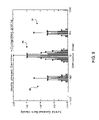
- FIG. 7 is a logarithmic plot of normalized intensities vs. diffraction orders resulting when the DOE of FIG. 5 is used to combine five ideally phased beams.
- FIG. 8 is a plot of another example of a periodic phase pattern in a five-beam combiner DOE having an added sinusoidal sampling grating.
- FIG. 9 is a logarithmic plot of normalized intensities of diffraction orders resulting when the DOE of FIG. 8 is used to combine five ideally phased beams.
- the diffractive beam combining method employs a DOE to enable the coherent combination of the output of a plurality of fiber amplifiers transmitting laser beams derived from a common oscillator.
- the beam combination method requires active phasing of the outputs from the fiber amplifiers to lock the phases of the output beams in order to optimize intensity of the composite beam by means of constructive interference. Active phasing is achieved by placing a beam splitter in the path of the composite beam that is diffracted by the DOE. The beam splitter produces a low power sample of the composite beam, and the sample is focused onto a phase detector.
- phase detector In the phase detector, the output phase of each constituent beam is detected by decoding signals that are encoded on each constituent beam. Using electronics, the phases are measured by comparison to reference signals from the master oscillator, and correction signals derived from this comparison are fed back to phase modulators in a low power section of each fiber amplifier to achieve optimal phasing.
- a beam combining method using passively phased fiber amplifiers is disclosed in U.S. patent application Ser. No. 11/015,671 filed Dec. 20, 2004, the entire disclosure thereof incorporated herein by reference.
- Passive phasing is achieved by placing a beam splitter in the path of a beam emitted from an array of fiber amplifiers.
- the beam splitter directs a small fraction of the composite beam to an aperture or coupling hole, which serves as a spatial filter.
- the output of the filter is coupled back to the input of each amplifier in the array. This creates positive feedback, causing the system to rapidly converge on a resonant mode with optimal spatial mode quality, thus synchronizing the phases of constituent beams that form the composite output.
- a DOE employed in a diffractive beam combining apparatus using passive phase control is now described.
- the fiber laser array is arranged in a ring configuration to exploit self-optimizing characteristics of positive feedback.
- Optical fiber amplifiers have a certain bandwidth over which they provide gain.
- Feedback is provided in a ring configuration by coupling a sample of the output beam back to the input.
- the frequency that has optimal phasing will experience the highest gain and will drive the circuit into saturation and suppress all other modes.
- U.S. patent application Ser. No. 11/015,671 for further detail regarding passive phasing of fiber amplifiers.
- One main advantage of passive phase control is greater simplicity, in that the master oscillator, the phase modulators, and the electronics used for phase control, as described in U.S. patent application Ser. No. 11/361,352, are not required.
- FIG. 1 shows an embodiment of an apparatus for diffractive beam combining according to the invention.
- the optical circuit in this embodiment uses passive phase control in conjunction with a DOE that functions as a beam combiner.
- Multiple (N) fiber amplifiers 15 are coupled and passively phased through a ring laser configuration.
- the N outputs of amplifiers 15 are coupled to fiber emitters 17 , which are arranged in a tiled or side-by-side one-dimensional or two-dimensional array 19 .
- fiber emitters 17 are selected to transmit beams of like polarization.
- This particular diagram shows five optical amplifiers 15 corresponding to five fiber emitters 17 , i.e. N has a value of 5. However, it should be appreciated that other embodiments are possible wherein N may assume any integer value.
- Divergent light beams 21 emerging from array 19 are collimated by a single reflective or transmissive collimating optic 23 , thereby forming a series of N collimated beams of full aperture with slightly differing propagation angles, appropriately determined by the spacing of fibers or other emitters in the array 19 .
- These N beams are overlapped and incident upon a properly designed DOE 25 employed as a beam combiner.
- the propagation angle of each of the N beams emerging from array 19 is precisely set to ensure alignment along a selected diffraction order direction of DOE 25 , such that the intensity of the composite output beam 27 of DOE 25 is maximized along a single diffraction order. In one embodiment, intensity of output beam 27 is maximized along the 0 th diffraction order.
- DOE 25 operates as a highly efficient 1:N beam splitter when one beam is incident, and may therefore operate as a highly efficient N:1 beam combiner when N beams are incident. That is, if the incident beams have the proper relative phase as determined by the design of DOE 25 , a single combined beam may be formed with very high efficiency, i.e. >>90%.
- the feedback loop may include one or more of a beam splitter 30 , optic 33 , aperture 34 , single mode fiber 36 , optical isolator 38 , pre-amplifier 40 , and fiber splitter 42 .
- beam splitter 30 may be placed in the path of composite beam 27 to produce a sample beam 31 , which represents a low power analog of composite beam 27 including any uncorrected phase variations.
- Beam splitter 30 directs sample 31 to an appropriate optic 33 (e.g. a lens or curved mirror).
- Optic 33 directs or focuses sample beam 31 to a filtering aperture 34 , which couples the beam to single mode fiber 36 .
- a suitably discriminatory pinhole filter may be used for spatial mode selection in place of single mode fiber 36 .
- Sample beam 31 may then be coupled through optical isolator 38 to pre-amplifier 40 , split through fiber splitter 42 , and injected back into the N amplifiers 15 to complete the ring.
- the ring oscillator attempts to maximize the round-trip gain, thus, it will passively self-optimize such that the relative phases of the N beams maximize the intensity of the combined output beam 27 , thereby maximizing the intensity of the feedback.
- This optimizes the efficiency of the ring oscillator, such that in an ideal case the output power of the single combined beam 27 will be the sum of the individual beam powers reduced only by the very high efficiency of DOE 25 .
- DOE 25 sums incident beams coherently, the ring laser configuration attempts to optimize the polarization of all the beams to be identical, which is required for the maximum efficiency of combination.
- polarization control may be achieved by other means, such as by using polarization maintaining fiber and appropriately adjusting polarization rotation optics in the ring laser.
- FIG. 2 illustrates another embodiment of a passively-phased beam combiner according to the invention.
- This embodiment operates in a manner very similar to the system of FIG. 1 , except that DOE 28 include an integral means for diffracting a low power sample 31 of output beam 27 into a passive feedback path.
- the low power diffracting means may be a highly reflective layer overcoated upon a weak grating (not shown) etched on the surface of DOE 28 .
- the weak grating generates the desired coherent diffracted sample 31 .
- DOE 28 may be a single optic with dual functions: combining plural input beams into a coherent output beam, and diffracting a low power sample of the coherent output.
- the dual-function DOE eliminates the need for placing a beam splitter in the output path to effect beam sampling. If a separate transmissive element such as a beam splitter 30 is used for sampling, heat accumulating inside the element may tend to deform its optical characteristics. This may lead to distortions in the output beam that render it less focusable. Generally speaking, minimizing the number of elements in the optical circuit better enables the system to achieve the diffraction limit.
- a dual-function DOE 39 includes a weak sampling grating designed to produce a low power sample 31 of the output beam, and also to focus sample beam 31 to filter 34 for coupling into single-mode fiber 36 .
- a focusing sampling grating may consist of grooves in the shape of rings rather than a simple array of parallel grooves. Ring-shaped grooves may be formed holographically by the interference of a plane wave and a point source located at the desired focal point.
- FIG. 4 illustrates an additional simplification that may be achieved in a passively phased diffractive beam combining system according to the invention.
- This embodiment uses passive phase control similar to the embodiments of FIGS. 1-3 .
- a DOE 41 is configured to perform the following functions: (i) collimating input beams 21 , (ii) combining the input beams into a coherent output beam 27 , (iii) diffracting a low power sample beam 31 of the coherent output, and (iv) focusing sample beam 31 for coupling into single-mode fiber 36 .
- An advantage of this embodiment is that no collimation optic is required for the fiber array.
- a single multi-function DOE 41 may be the only optical element in the system.
- a DOE 41 One method for manufacturing a DOE 41 is to fabricate it on an appropriately curved substrate. Alternately, the DOE could be designed with an additional phase variation of a kinoform lens. As is well known in the art, the kinoform is a curved shape fabricated modulo phase of a multiple of 2 ⁇ .
- the various DOEs depicted in the figures are modeled as primarily reflective optical elements.
- the DOE comprises a highly reflective dielectric stack on it surface having greater than 99% reflectivity to minimize power absorption.
- any DOE described herein may be fabricated as a transmissive element.
- reflective elements are preferred primarily because the non-reflecting side of a reflective element may be configured for cooling without introducing material into the optical path.
- DOE 41 is shown with an optional cooling means 42 abutting the non-reflecting side. Cooling means 42 may be any type of heat sink suitable for removing heat from DOE 41 to ensure optical stability.
- cooling means 42 may be a finned metal heat sink contacted to the DOE by an adhesive with high thermal conductivity, a surface exposed to forced air, a conduit for the flow of coolant such as water, or a combination of any of the foregoing.
- DOEs can be designed to efficiently combine or split an arbitrarily large number of beams, in 1D or 2D arrays.
- the subject DOE has a pattern of parallel precisely-shaped main grooves etched on its surface, which upon reflection or transmission produces the 1D periodic phase pattern 43 plotted in FIG. 5 in waves (one wave equals 2 ⁇ radians).
- one wave of phase corresponds to an etch depth of ⁇ /2 or ⁇ /(n ⁇ 1), respectively, where n is the index of refraction of the DOE substrate and ⁇ is the wavelength.
- ⁇ is the wavelength and P is the period of the phase pattern on the DOE.
- FIGS. 8-9 illustrate the sampling capability of a DOE.
- the design of the five-beam combiner DOE of FIG. 6 may be modified by adding a weak, short-period sinusoidal sampling grating.
- the peak-to-peak phase value of this particular sampling grating is selected as 1/50 th of a wave.
- a plot of the phase of the modified DOE with sampling grating is shown in FIG. 8 .
- the resulting phase pattern 47 appears as the short-period sinusoid superimposed on periodic phase pattern 43 .
- phased input beams are diffracted to produce the output shown in FIG. 9 . Note that in FIG.
- the central group of diffraction order intensities 45 centered about the 0 th order is the same relative distribution of intensities shown in the plot of FIG. 6 .
- the left-hand diffraction order intensities 49 , and right-hand diffraction order intensities 51 are centered about the ⁇ 50 th and +50 th orders, respectively.
- Each of these intensity groups 49 and 51 provides a low-power representation of the distribution of intensities 45 .
- the DOE embodiment illustrated in FIGS. 8-9 has sampling grating grooves situated in parallel to the main grooves and therefore the sampled beam is in the same plane as the fiber array and spurious diffracted output beams.
- the period of the sampling grating in this example is taken to be 1/50 th of the DOE combiner period, and thus the beam sample is diffracted at an angle corresponding to the ⁇ 50 th diffracted order of the combiner.
- the sampled beam diffraction order intensities 49 and 51 are well separated from the spurious diffracted orders of the DOE combiner function. Skilled artisans should recognize that many other DOE embodiments are possible, wherein a sampling grating comprising a set of grooves is applied in any direction relative to the DOE combiner function such that the sampled beam departs the DOE in any convenient direction.
- the sampling grating phase depth is selected to be 1/50 th of a wave.
- the sample intensity in either of the two ⁇ 50 th sampled orders is approximately 1 ⁇ 10 ⁇ 3 of the main (0 th order) output beam.
- each of the primary sampled ⁇ 50 th orders provides an identical low power copy of the fully combined beam.
- a weak sinusoidal phase grating can be adjusted according to a desired sample fraction of approximately 2.5 ⁇ 2 , where ⁇ 2 is the peak-to-peak phase amplitude of the grating measured in waves.
- the sinusoidal shape of a sampling grating leads to equal sampled beam intensities in both ⁇ 50 th orders.
- a “blazed” (i.e. more triangular) shape can be used to preferentially diffract light primarily into one of these orders, as is well understood in the grating art.
- a system employing such an optic minimizes the total number of elements in the optical path. This simplifies system construction and alignment of the elements within the system. Having fewer optical elements in the system also reduces the probability of introducing distortion in the optical signal, which leads to better combination efficiency and higher intensity in the output beam.
- the integrated DOE combiner and sampler also simplifies heat removal. In one respect, heat removal is simplified because the heat energy accumulates on fewer elements. In another respect, the reflective characteristic of the DOE combiner/sampler allows heat transfer through the non-reflective side. In large scale systems, a weight reduction advantage is also achieved through component minimization.
Abstract
Description
sin θm =mλ/P (1)
Claims (20)
Priority Applications (3)
| Application Number | Priority Date | Filing Date | Title |
|---|---|---|---|
| US11/543,613 US7339727B1 (en) | 2003-01-30 | 2006-10-05 | Method and system for diffractive beam combining using DOE combiner with passive phase control |
| DE112007002367T DE112007002367B9 (en) | 2006-10-05 | 2007-09-12 | Method and system for the diffractive combination of beams through a DOE beamformer with passive phase control |
| PCT/US2007/078272 WO2008045652A2 (en) | 2006-10-05 | 2007-09-12 | Method and system for diffractive beam combining using doe combiner with passive phase control |
Applications Claiming Priority (3)
| Application Number | Priority Date | Filing Date | Title |
|---|---|---|---|
| GBGB0302215.9A GB0302215D0 (en) | 2003-01-30 | 2003-01-30 | Method and system for determining optimum resourse allocation in a network |
| PCT/GB2004/000293 WO2004068802A1 (en) | 2003-01-30 | 2004-01-23 | Method and system for determining optimum resource allocation in a network |
| US11/543,613 US7339727B1 (en) | 2003-01-30 | 2006-10-05 | Method and system for diffractive beam combining using DOE combiner with passive phase control |
Publications (1)
| Publication Number | Publication Date |
|---|---|
| US7339727B1 true US7339727B1 (en) | 2008-03-04 |
Family
ID=39135347
Family Applications (1)
| Application Number | Title | Priority Date | Filing Date |
|---|---|---|---|
| US11/543,613 Active US7339727B1 (en) | 2003-01-30 | 2006-10-05 | Method and system for diffractive beam combining using DOE combiner with passive phase control |
Country Status (1)
| Country | Link |
|---|---|
| US (1) | US7339727B1 (en) |
Cited By (24)
| Publication number | Priority date | Publication date | Assignee | Title |
|---|---|---|---|---|
| US20100315699A1 (en) * | 2009-06-15 | 2010-12-16 | The Boeing Company | Phase Control and Locking Method for Coherently Combining High-Gain Multi-Stage Fiber Amplifiers |
| US20110032602A1 (en) * | 2009-08-07 | 2011-02-10 | Northrop Grumman Space & Mission Systems Corp. | All-fiber integrated high power coherent beam combination |
| US20110032604A1 (en) * | 2009-08-07 | 2011-02-10 | Northrop Grumman Space & Mission Systems Corp. | Passive all-fiber integrated high power coherent beam combination |
| US20110032603A1 (en) * | 2009-08-07 | 2011-02-10 | Northcrop Grumman Space & Mission Systems Corp. | Integrated spectral and all-fiber coherent beam combination |
| US20110222574A1 (en) * | 2010-03-09 | 2011-09-15 | Massachusetts Institute Of Technology | Two-dimensional wavelength-beam-combining of lasers using first-order grating stack |
| US20110292498A1 (en) * | 2010-05-27 | 2011-12-01 | Massachusetts Institute Of Technology | High peak power optical amplifier |
| US8531772B2 (en) | 2008-11-04 | 2013-09-10 | Massachusetts Institute Of Technology | External-cavity one-dimensional multi-wavelength beam combining of two-dimensional laser elements |
| US20130342896A1 (en) * | 2010-12-06 | 2013-12-26 | Compagnie Industrielle Des Lasers-Cilas | Method and laser oscillator for the generation of a laser beam |
| US20140153594A1 (en) * | 2012-11-30 | 2014-06-05 | Industrial Technology Research Institute | Apparatus for generating pulse train with adjustable time interval |
| US20150055666A1 (en) * | 2012-03-30 | 2015-02-26 | Heriot-Watt University | Fibre laser |
| WO2013176927A3 (en) * | 2012-05-24 | 2015-05-21 | Northrop Grumman Systems Corporation | Coherent laser array control system and method |
| CN105552713A (en) * | 2016-02-24 | 2016-05-04 | 苏州大学 | Multi-wavelength external cavity laser for non-fluorescence raman spectrometer |
| US9502854B1 (en) * | 2015-08-26 | 2016-11-22 | Raytheon Company | Self-seeding high power laser |
| US9575341B2 (en) | 2014-06-28 | 2017-02-21 | Intel Corporation | Solid state LIDAR circuit with waveguides tunable to separate phase offsets |
| US9620928B2 (en) | 2010-07-16 | 2017-04-11 | Massachusetts Institute Of Technology | Continuous wave or ultrafast lasers |
| US10048163B1 (en) * | 2013-12-19 | 2018-08-14 | Apple Inc. | Monitoring DOE performance using total internal reflection |
| US10073004B2 (en) | 2016-09-19 | 2018-09-11 | Apple Inc. | DOE defect monitoring utilizing total internal reflection |
| US20180267325A1 (en) * | 2016-02-16 | 2018-09-20 | Gerald Ho Kim | Two-Dimensional Coherent Beam Combination Using Circular Or Spiral Diffraction Grating |
| US10180493B2 (en) | 2014-08-15 | 2019-01-15 | Quanergy Systems, Inc. | Three-dimensional-mapping two-dimensional-scanning LIDAR based on one-dimensional-steering optical phased arrays and method of using same |
| CN110459937A (en) * | 2018-05-08 | 2019-11-15 | 华为技术有限公司 | Laser |
| US10613201B2 (en) | 2014-10-20 | 2020-04-07 | Quanergy Systems, Inc. | Three-dimensional lidar sensor based on two-dimensional scanning of one-dimensional optical emitter and method of using same |
| KR20200076735A (en) * | 2017-11-07 | 2020-06-29 | 시반 어드밴스드 테크놀러지스 엘티디. | Optical phased array dynamic beam shaping using noise correction |
| US11150332B1 (en) * | 2020-06-30 | 2021-10-19 | Apple Inc. | Self-calibrating optical transceiver system with reduced crosstalk sensitivity for through-display proximity sensing |
| CN114986001A (en) * | 2022-06-10 | 2022-09-02 | 北京工业大学 | Ultra-thin plate dissimilar metal welding method |
Citations (27)
| Publication number | Priority date | Publication date | Assignee | Title |
|---|---|---|---|---|
| US5373526A (en) * | 1992-05-12 | 1994-12-13 | Hughes Aircraft Company | Apparatus and method for optical energy amplification using two-beam coupling |
| US5572542A (en) * | 1995-04-13 | 1996-11-05 | Amoco Corporation | Technique for locking an external cavity large-area laser diode to a passive optical cavity |
| US5629992A (en) * | 1995-09-14 | 1997-05-13 | Bell Communications Research, Inc. | Passband flattening of integrated optical filters |
| US5694408A (en) * | 1995-06-07 | 1997-12-02 | Mcdonnell Douglas Corporation | Fiber optic laser system and associated lasing method |
| US5717516A (en) * | 1996-03-01 | 1998-02-10 | Hughes Electronics | Hybrid laser power combining and beam cleanup system using nonlinear and adaptive optical wavefront compensation |
| US5835199A (en) * | 1996-05-17 | 1998-11-10 | Coherent Technologies | Fiber-based ladar transceiver for range/doppler imaging with frequency comb generator |
| US6192062B1 (en) | 1998-09-08 | 2001-02-20 | Massachusetts Institute Of Technology | Beam combining of diode laser array elements for high brightness and power |
| US6208679B1 (en) | 1998-09-08 | 2001-03-27 | Massachusetts Institute Of Technology | High-power multi-wavelength external cavity laser |
| US6317257B1 (en) * | 2000-04-20 | 2001-11-13 | Trw Inc. | Technique for polarization locking optical outputs |
| US6327292B1 (en) | 1998-09-08 | 2001-12-04 | Massachusetts Institute Of Technology | External cavity laser source using spectral beam combining in two dimensions |
| US6366356B1 (en) | 1999-04-01 | 2002-04-02 | Trw Inc. | High average power fiber laser system with high-speed, parallel wavefront sensor |
| US6480327B1 (en) * | 2000-09-11 | 2002-11-12 | Hrl Laboratories, Llc | High power laser system with fiber amplifiers and loop PCM |
| US20030062468A1 (en) * | 2001-09-28 | 2003-04-03 | Byren Robert W. | System and method for effecting high-power beam control with adaptive optics in low power beam path |
| US6597836B2 (en) * | 2001-06-20 | 2003-07-22 | The Boeing Company | Optical phased array control system |
| US6678294B1 (en) * | 2000-11-06 | 2004-01-13 | Northrop Grumman Corporation | Distributed feedback laser apparatus for avoiding stimulated brillouin scattering |
| US6678288B2 (en) * | 2002-06-10 | 2004-01-13 | The Boeing Company | Multi-aperture fiber laser system |
| US6697192B1 (en) | 2000-11-08 | 2004-02-24 | Massachusetts Institute Of Technology | High power, spectrally combined laser systems and related methods |
| US6708003B1 (en) | 1999-12-16 | 2004-03-16 | Northrop Grumman Corporation | Optical energy transmission system utilizing precise phase and amplitude control |
| US6717719B1 (en) * | 2001-10-01 | 2004-04-06 | The United States Of America As Represented By The Secretary Of The Air Force | Coherent optical beam combination using double-coated glass mirrors/mirror pairs |
| US6724125B2 (en) * | 1999-03-30 | 2004-04-20 | Massachusetts Institute Of Technology | Methods and apparatus for diffractive optical processing using an actuatable structure |
| US6813069B2 (en) * | 2003-01-24 | 2004-11-02 | The Boeing Company | Method and apparatus for controlling a fiber optic phased array utilizing frequency shifting |
| US20050035295A1 (en) * | 2003-06-06 | 2005-02-17 | Brett Bouma | Process and apparatus for a wavelength tuning source |
| US20050135815A1 (en) * | 2003-12-17 | 2005-06-23 | The Boeing Company | Fiber optic phased array and associated method for accommodating atmospheric perturbations with phase and amplitude control |
| US7088743B2 (en) * | 2004-03-15 | 2006-08-08 | Northrop Grumman Corp. | Laser source comprising amplifier and adaptive wavefront/polarization driver |
| US20060187537A1 (en) * | 2005-01-20 | 2006-08-24 | Robert Huber | Mode locking methods and apparatus |
| US7212285B2 (en) * | 2004-07-14 | 2007-05-01 | Fujitsu Limited | Optical measurement device |
| US7221499B2 (en) * | 2005-10-19 | 2007-05-22 | Northrop Grumman Corporation | Frequency scanned array control system |
-
2006
- 2006-10-05 US US11/543,613 patent/US7339727B1/en active Active
Patent Citations (27)
| Publication number | Priority date | Publication date | Assignee | Title |
|---|---|---|---|---|
| US5373526A (en) * | 1992-05-12 | 1994-12-13 | Hughes Aircraft Company | Apparatus and method for optical energy amplification using two-beam coupling |
| US5572542A (en) * | 1995-04-13 | 1996-11-05 | Amoco Corporation | Technique for locking an external cavity large-area laser diode to a passive optical cavity |
| US5694408A (en) * | 1995-06-07 | 1997-12-02 | Mcdonnell Douglas Corporation | Fiber optic laser system and associated lasing method |
| US5629992A (en) * | 1995-09-14 | 1997-05-13 | Bell Communications Research, Inc. | Passband flattening of integrated optical filters |
| US5717516A (en) * | 1996-03-01 | 1998-02-10 | Hughes Electronics | Hybrid laser power combining and beam cleanup system using nonlinear and adaptive optical wavefront compensation |
| US5835199A (en) * | 1996-05-17 | 1998-11-10 | Coherent Technologies | Fiber-based ladar transceiver for range/doppler imaging with frequency comb generator |
| US6192062B1 (en) | 1998-09-08 | 2001-02-20 | Massachusetts Institute Of Technology | Beam combining of diode laser array elements for high brightness and power |
| US6208679B1 (en) | 1998-09-08 | 2001-03-27 | Massachusetts Institute Of Technology | High-power multi-wavelength external cavity laser |
| US6327292B1 (en) | 1998-09-08 | 2001-12-04 | Massachusetts Institute Of Technology | External cavity laser source using spectral beam combining in two dimensions |
| US6724125B2 (en) * | 1999-03-30 | 2004-04-20 | Massachusetts Institute Of Technology | Methods and apparatus for diffractive optical processing using an actuatable structure |
| US6366356B1 (en) | 1999-04-01 | 2002-04-02 | Trw Inc. | High average power fiber laser system with high-speed, parallel wavefront sensor |
| US6708003B1 (en) | 1999-12-16 | 2004-03-16 | Northrop Grumman Corporation | Optical energy transmission system utilizing precise phase and amplitude control |
| US6317257B1 (en) * | 2000-04-20 | 2001-11-13 | Trw Inc. | Technique for polarization locking optical outputs |
| US6480327B1 (en) * | 2000-09-11 | 2002-11-12 | Hrl Laboratories, Llc | High power laser system with fiber amplifiers and loop PCM |
| US6678294B1 (en) * | 2000-11-06 | 2004-01-13 | Northrop Grumman Corporation | Distributed feedback laser apparatus for avoiding stimulated brillouin scattering |
| US6697192B1 (en) | 2000-11-08 | 2004-02-24 | Massachusetts Institute Of Technology | High power, spectrally combined laser systems and related methods |
| US6597836B2 (en) * | 2001-06-20 | 2003-07-22 | The Boeing Company | Optical phased array control system |
| US20030062468A1 (en) * | 2001-09-28 | 2003-04-03 | Byren Robert W. | System and method for effecting high-power beam control with adaptive optics in low power beam path |
| US6717719B1 (en) * | 2001-10-01 | 2004-04-06 | The United States Of America As Represented By The Secretary Of The Air Force | Coherent optical beam combination using double-coated glass mirrors/mirror pairs |
| US6678288B2 (en) * | 2002-06-10 | 2004-01-13 | The Boeing Company | Multi-aperture fiber laser system |
| US6813069B2 (en) * | 2003-01-24 | 2004-11-02 | The Boeing Company | Method and apparatus for controlling a fiber optic phased array utilizing frequency shifting |
| US20050035295A1 (en) * | 2003-06-06 | 2005-02-17 | Brett Bouma | Process and apparatus for a wavelength tuning source |
| US20050135815A1 (en) * | 2003-12-17 | 2005-06-23 | The Boeing Company | Fiber optic phased array and associated method for accommodating atmospheric perturbations with phase and amplitude control |
| US7088743B2 (en) * | 2004-03-15 | 2006-08-08 | Northrop Grumman Corp. | Laser source comprising amplifier and adaptive wavefront/polarization driver |
| US7212285B2 (en) * | 2004-07-14 | 2007-05-01 | Fujitsu Limited | Optical measurement device |
| US20060187537A1 (en) * | 2005-01-20 | 2006-08-24 | Robert Huber | Mode locking methods and apparatus |
| US7221499B2 (en) * | 2005-10-19 | 2007-05-22 | Northrop Grumman Corporation | Frequency scanned array control system |
Non-Patent Citations (1)
| Title |
|---|
| Shay, T.M. & Benham, V. "First Experimental Demonstration of Phase Locking of Optical Fiber Arrays by RF Phase Modulation". Proceedings of SPIE vol. 5550. pp. 313-319 (2004). |
Cited By (50)
| Publication number | Priority date | Publication date | Assignee | Title |
|---|---|---|---|---|
| US8531772B2 (en) | 2008-11-04 | 2013-09-10 | Massachusetts Institute Of Technology | External-cavity one-dimensional multi-wavelength beam combining of two-dimensional laser elements |
| US20100315699A1 (en) * | 2009-06-15 | 2010-12-16 | The Boeing Company | Phase Control and Locking Method for Coherently Combining High-Gain Multi-Stage Fiber Amplifiers |
| US8184362B2 (en) * | 2009-06-15 | 2012-05-22 | The Boeing Company | Phase control and locking method for coherently combining high-gain multi-stage fiber amplifiers |
| US8488235B2 (en) * | 2009-08-07 | 2013-07-16 | Northrop Grumman Systems Corporation | Multi-channel fiber laser amplifier combining apparatus including a tapered fiber bundle having multiple fiber outputs |
| US20130148193A1 (en) * | 2009-08-07 | 2013-06-13 | Northrop Grumman Systems Corporation | Fiber amplifier system including tapered fiber bundle and combined lens and sampling grating |
| US20110032603A1 (en) * | 2009-08-07 | 2011-02-10 | Northcrop Grumman Space & Mission Systems Corp. | Integrated spectral and all-fiber coherent beam combination |
| US20110032604A1 (en) * | 2009-08-07 | 2011-02-10 | Northrop Grumman Space & Mission Systems Corp. | Passive all-fiber integrated high power coherent beam combination |
| US8184361B2 (en) | 2009-08-07 | 2012-05-22 | Northrop Grumman Systems Corporation | Integrated spectral and all-fiber coherent beam combination |
| US8184363B2 (en) * | 2009-08-07 | 2012-05-22 | Northrop Grumman Systems Corporation | All-fiber integrated high power coherent beam combination |
| US20120212801A1 (en) * | 2009-08-07 | 2012-08-23 | Northrop Grumman Systems Corporation | Multi-channel fiber laser amplifier combining apparatus including a tapered fiber bundle having multiple fiber outputs |
| US8922881B2 (en) * | 2009-08-07 | 2014-12-30 | Northrop Grumman Systems Corporation | Fiber amplifier system including tapered fiber bundle and polarization control |
| US20130148191A1 (en) * | 2009-08-07 | 2013-06-13 | Northrop Grumman Systems Corporation | Fiber amplifier system including tapered fiber bundle and polarization control |
| US8958145B2 (en) * | 2009-08-07 | 2015-02-17 | Northrop Grumman Systems Corporation | Fiber amplifier system including tapered fiber bundle and combined lens and sampling grating |
| US8514485B2 (en) | 2009-08-07 | 2013-08-20 | Northrop Grumman Systems Corporation | Passive all-fiber integrated high power coherent beam combination |
| US20110032602A1 (en) * | 2009-08-07 | 2011-02-10 | Northrop Grumman Space & Mission Systems Corp. | All-fiber integrated high power coherent beam combination |
| US9575325B2 (en) | 2010-03-09 | 2017-02-21 | Massachusetts Institute Of Technology | Two-dimensional wavelength-beam-combining of lasers using first-order grating stack |
| US8614853B2 (en) | 2010-03-09 | 2013-12-24 | Massachusetts Institute Of Technology | Two-dimensional wavelength-beam-combining of lasers using first-order grating stack |
| US20110222574A1 (en) * | 2010-03-09 | 2011-09-15 | Massachusetts Institute Of Technology | Two-dimensional wavelength-beam-combining of lasers using first-order grating stack |
| US20110292498A1 (en) * | 2010-05-27 | 2011-12-01 | Massachusetts Institute Of Technology | High peak power optical amplifier |
| US8531761B2 (en) * | 2010-05-27 | 2013-09-10 | Massachusetts Institute Of Technology | High peak power optical amplifier |
| US9136667B2 (en) | 2010-05-27 | 2015-09-15 | Massachusetts Institute Of Technology | High peak power optical amplifier |
| US9620928B2 (en) | 2010-07-16 | 2017-04-11 | Massachusetts Institute Of Technology | Continuous wave or ultrafast lasers |
| US9166359B2 (en) * | 2010-12-06 | 2015-10-20 | Compagnie Industrielle Des Lasers Cilas | Method and laser oscillator for the generation of a laser beam |
| US20130342896A1 (en) * | 2010-12-06 | 2013-12-26 | Compagnie Industrielle Des Lasers-Cilas | Method and laser oscillator for the generation of a laser beam |
| US20150055666A1 (en) * | 2012-03-30 | 2015-02-26 | Heriot-Watt University | Fibre laser |
| US9601894B2 (en) * | 2012-03-30 | 2017-03-21 | Heriot-Watt University | Fibre laser |
| WO2013176927A3 (en) * | 2012-05-24 | 2015-05-21 | Northrop Grumman Systems Corporation | Coherent laser array control system and method |
| US8995054B2 (en) * | 2012-11-30 | 2015-03-31 | Industrial Technology Research Institute | Apparatus for generating pulse train with adjustable time interval |
| US20140153594A1 (en) * | 2012-11-30 | 2014-06-05 | Industrial Technology Research Institute | Apparatus for generating pulse train with adjustable time interval |
| US10048163B1 (en) * | 2013-12-19 | 2018-08-14 | Apple Inc. | Monitoring DOE performance using total internal reflection |
| US9575341B2 (en) | 2014-06-28 | 2017-02-21 | Intel Corporation | Solid state LIDAR circuit with waveguides tunable to separate phase offsets |
| US10180493B2 (en) | 2014-08-15 | 2019-01-15 | Quanergy Systems, Inc. | Three-dimensional-mapping two-dimensional-scanning LIDAR based on one-dimensional-steering optical phased arrays and method of using same |
| US10613201B2 (en) | 2014-10-20 | 2020-04-07 | Quanergy Systems, Inc. | Three-dimensional lidar sensor based on two-dimensional scanning of one-dimensional optical emitter and method of using same |
| US9502854B1 (en) * | 2015-08-26 | 2016-11-22 | Raytheon Company | Self-seeding high power laser |
| JP2018525845A (en) * | 2015-08-26 | 2018-09-06 | レイセオン カンパニー | Self-seeding high power laser |
| US20180267325A1 (en) * | 2016-02-16 | 2018-09-20 | Gerald Ho Kim | Two-Dimensional Coherent Beam Combination Using Circular Or Spiral Diffraction Grating |
| US10732426B2 (en) * | 2016-02-16 | 2020-08-04 | Gerald Ho Kim | Two-dimensional coherent beam combination using circular or spiral diffraction grating |
| CN105552713A (en) * | 2016-02-24 | 2016-05-04 | 苏州大学 | Multi-wavelength external cavity laser for non-fluorescence raman spectrometer |
| CN105552713B (en) * | 2016-02-24 | 2018-10-16 | 苏州大学 | Multi-wavelength outside cavity gas laser for unstressed configuration Raman spectrometer |
| US10073004B2 (en) | 2016-09-19 | 2018-09-11 | Apple Inc. | DOE defect monitoring utilizing total internal reflection |
| KR20220118552A (en) * | 2017-11-07 | 2022-08-25 | 시반 어드밴스드 테크놀러지스 엘티디. | Optical phased array dynamic beam shaping with noise correction |
| US11646543B2 (en) * | 2017-11-07 | 2023-05-09 | Civan Advanced Technologies Ltd. | Optical phased array dynamic beam shaping with noise correction |
| KR20200076735A (en) * | 2017-11-07 | 2020-06-29 | 시반 어드밴스드 테크놀러지스 엘티디. | Optical phased array dynamic beam shaping using noise correction |
| US20210175680A1 (en) * | 2017-11-07 | 2021-06-10 | Civan Advanced Technologies Ltd. | Optical phased array dynamic beam shaping with noise correction |
| EP3707789A4 (en) * | 2017-11-07 | 2021-08-18 | Civan Advanced Technologies Ltd. | Optical phased array dynamic beam shaping with noise correction |
| CN110459937B (en) * | 2018-05-08 | 2021-03-23 | 华为技术有限公司 | Laser device |
| CN110459937A (en) * | 2018-05-08 | 2019-11-15 | 华为技术有限公司 | Laser |
| US11150332B1 (en) * | 2020-06-30 | 2021-10-19 | Apple Inc. | Self-calibrating optical transceiver system with reduced crosstalk sensitivity for through-display proximity sensing |
| CN114986001A (en) * | 2022-06-10 | 2022-09-02 | 北京工业大学 | Ultra-thin plate dissimilar metal welding method |
| CN114986001B (en) * | 2022-06-10 | 2024-03-29 | 北京工业大学 | Method for welding dissimilar metals of ultrathin plate |
Similar Documents
| Publication | Publication Date | Title |
|---|---|---|
| US7339727B1 (en) | Method and system for diffractive beam combining using DOE combiner with passive phase control | |
| US7468832B2 (en) | Method and system for coherent beam combining using an integrated diffractive beam combiner and sampler | |
| US7436588B2 (en) | Method and system for hybrid coherent and incoherent diffractive beam combining | |
| US7346085B1 (en) | Multi-stage method and system for coherent diffractive beam combining | |
| US7440174B2 (en) | Coherent fiber diffractive optical element beam combiner | |
| US9690107B2 (en) | Device for wavelength combining of laser beams | |
| US9596034B2 (en) | High brightness dense wavelength multiplexing laser | |
| US20020181035A1 (en) | Method and system for combining multiple low power laser sources to achieve high efficiency, high power outputs using transmission holographic methodologies | |
| US8073020B2 (en) | Wavelength tuning apparatus and method thereof | |
| US7336363B2 (en) | Interferometric beam combination | |
| US6714581B2 (en) | Compact phase locked laser array and related techniques | |
| EP0663606B1 (en) | Laser beam scanning radiating apparatus | |
| US11446776B2 (en) | Method for assembling a hollow core optical fiber array launcher | |
| EP0661785B1 (en) | Laser apparatus | |
| US6501782B1 (en) | Compact laser apparatus | |
| US6487022B1 (en) | Transmitter using uniform intensity transmission for a wireless optical communication system | |
| US20130259071A1 (en) | Broadband optical accumulator and tunable laser using a supercontinuum cavity | |
| CN113394653B (en) | Laser coherent array and control method | |
| US20060132903A1 (en) | Passive phasing of fiber amplifiers | |
| WO2008045652A2 (en) | Method and system for diffractive beam combining using doe combiner with passive phase control | |
| US11269136B1 (en) | Hollow core optical fiber array launcher with sealed lens block | |
| US7539232B1 (en) | Compact phase locked laser array and related techniques | |
| US20210043790A1 (en) | Spectral Solar Cells | |
| EP4198614A1 (en) | Wavelength beam combining device, direct diode laser device, and laser processing machine | |
| JP2589799B2 (en) | Laser optics |
Legal Events
| Date | Code | Title | Description |
|---|---|---|---|
| AS | Assignment |
Owner name: NORTHROP GRUMMAN CORPORATION, CALIFORNIA Free format text: ASSIGNMENT OF ASSIGNORS INTEREST;ASSIGNORS:ROTHENBERG, JOSHUA E.;RICE, ROBERT R.;SHAKIR, SAMI A.;AND OTHERS;REEL/FRAME:019326/0472;SIGNING DATES FROM 20061002 TO 20061004 |
|
| FEPP | Fee payment procedure |
Free format text: PAYOR NUMBER ASSIGNED (ORIGINAL EVENT CODE: ASPN); ENTITY STATUS OF PATENT OWNER: LARGE ENTITY |
|
| STCF | Information on status: patent grant |
Free format text: PATENTED CASE |
|
| AS | Assignment |
Owner name: NORTHROP GRUMMAN SPACE & MISSION SYSTEMS CORP.,CAL Free format text: ASSIGNMENT OF ASSIGNORS INTEREST;ASSIGNOR:NORTHROP GRUMMAN CORPORTION;REEL/FRAME:023699/0551 Effective date: 20091125 Owner name: NORTHROP GRUMMAN SPACE & MISSION SYSTEMS CORP., CA Free format text: ASSIGNMENT OF ASSIGNORS INTEREST;ASSIGNOR:NORTHROP GRUMMAN CORPORTION;REEL/FRAME:023699/0551 Effective date: 20091125 |
|
| AS | Assignment |
Owner name: NORTHROP GRUMMAN SYSTEMS CORPORATION,CALIFORNIA Free format text: ASSIGNMENT OF ASSIGNORS INTEREST;ASSIGNOR:NORTHROP GRUMMAN SPACE & MISSION SYSTEMS CORP.;REEL/FRAME:023915/0446 Effective date: 20091210 Owner name: NORTHROP GRUMMAN SYSTEMS CORPORATION, CALIFORNIA Free format text: ASSIGNMENT OF ASSIGNORS INTEREST;ASSIGNOR:NORTHROP GRUMMAN SPACE & MISSION SYSTEMS CORP.;REEL/FRAME:023915/0446 Effective date: 20091210 |
|
| FPAY | Fee payment |
Year of fee payment: 4 |
|
| FPAY | Fee payment |
Year of fee payment: 8 |
|
| MAFP | Maintenance fee payment |
Free format text: PAYMENT OF MAINTENANCE FEE, 12TH YEAR, LARGE ENTITY (ORIGINAL EVENT CODE: M1553); ENTITY STATUS OF PATENT OWNER: LARGE ENTITY Year of fee payment: 12 |