US7328556B2 - Bag sealing system and method - Google Patents
Bag sealing system and method Download PDFInfo
- Publication number
- US7328556B2 US7328556B2 US11/073,559 US7355905A US7328556B2 US 7328556 B2 US7328556 B2 US 7328556B2 US 7355905 A US7355905 A US 7355905A US 7328556 B2 US7328556 B2 US 7328556B2
- Authority
- US
- United States
- Prior art keywords
- sealing
- bag
- sealing bar
- platen
- neck
- Prior art date
- Legal status (The legal status is an assumption and is not a legal conclusion. Google has not performed a legal analysis and makes no representation as to the accuracy of the status listed.)
- Expired - Lifetime, expires
Links
Images


Classifications
-
- B—PERFORMING OPERATIONS; TRANSPORTING
- B29—WORKING OF PLASTICS; WORKING OF SUBSTANCES IN A PLASTIC STATE IN GENERAL
- B29C—SHAPING OR JOINING OF PLASTICS; SHAPING OF MATERIAL IN A PLASTIC STATE, NOT OTHERWISE PROVIDED FOR; AFTER-TREATMENT OF THE SHAPED PRODUCTS, e.g. REPAIRING
- B29C65/00—Joining or sealing of preformed parts, e.g. welding of plastics materials; Apparatus therefor
- B29C65/02—Joining or sealing of preformed parts, e.g. welding of plastics materials; Apparatus therefor by heating, with or without pressure
- B29C65/18—Joining or sealing of preformed parts, e.g. welding of plastics materials; Apparatus therefor by heating, with or without pressure using heated tools
- B29C65/24—Joining or sealing of preformed parts, e.g. welding of plastics materials; Apparatus therefor by heating, with or without pressure using heated tools characterised by the means for heating the tool
- B29C65/30—Electrical means
- B29C65/305—Electrical means involving the use of cartridge heaters
-
- B—PERFORMING OPERATIONS; TRANSPORTING
- B29—WORKING OF PLASTICS; WORKING OF SUBSTANCES IN A PLASTIC STATE IN GENERAL
- B29C—SHAPING OR JOINING OF PLASTICS; SHAPING OF MATERIAL IN A PLASTIC STATE, NOT OTHERWISE PROVIDED FOR; AFTER-TREATMENT OF THE SHAPED PRODUCTS, e.g. REPAIRING
- B29C65/00—Joining or sealing of preformed parts, e.g. welding of plastics materials; Apparatus therefor
- B29C65/02—Joining or sealing of preformed parts, e.g. welding of plastics materials; Apparatus therefor by heating, with or without pressure
- B29C65/18—Joining or sealing of preformed parts, e.g. welding of plastics materials; Apparatus therefor by heating, with or without pressure using heated tools
- B29C65/24—Joining or sealing of preformed parts, e.g. welding of plastics materials; Apparatus therefor by heating, with or without pressure using heated tools characterised by the means for heating the tool
- B29C65/30—Electrical means
-
- B—PERFORMING OPERATIONS; TRANSPORTING
- B29—WORKING OF PLASTICS; WORKING OF SUBSTANCES IN A PLASTIC STATE IN GENERAL
- B29C—SHAPING OR JOINING OF PLASTICS; SHAPING OF MATERIAL IN A PLASTIC STATE, NOT OTHERWISE PROVIDED FOR; AFTER-TREATMENT OF THE SHAPED PRODUCTS, e.g. REPAIRING
- B29C65/00—Joining or sealing of preformed parts, e.g. welding of plastics materials; Apparatus therefor
- B29C65/74—Joining or sealing of preformed parts, e.g. welding of plastics materials; Apparatus therefor by welding and severing, or by joining and severing, the severing being performed in the area to be joined, next to the area to be joined, in the joint area or next to the joint area
- B29C65/745—Joining or sealing of preformed parts, e.g. welding of plastics materials; Apparatus therefor by welding and severing, or by joining and severing, the severing being performed in the area to be joined, next to the area to be joined, in the joint area or next to the joint area using a single unit having both a severing tool and a welding tool
- B29C65/7451—Joining or sealing of preformed parts, e.g. welding of plastics materials; Apparatus therefor by welding and severing, or by joining and severing, the severing being performed in the area to be joined, next to the area to be joined, in the joint area or next to the joint area using a single unit having both a severing tool and a welding tool the severing tool and the welding tool being movable with respect to one-another
-
- B—PERFORMING OPERATIONS; TRANSPORTING
- B29—WORKING OF PLASTICS; WORKING OF SUBSTANCES IN A PLASTIC STATE IN GENERAL
- B29C—SHAPING OR JOINING OF PLASTICS; SHAPING OF MATERIAL IN A PLASTIC STATE, NOT OTHERWISE PROVIDED FOR; AFTER-TREATMENT OF THE SHAPED PRODUCTS, e.g. REPAIRING
- B29C65/00—Joining or sealing of preformed parts, e.g. welding of plastics materials; Apparatus therefor
- B29C65/74—Joining or sealing of preformed parts, e.g. welding of plastics materials; Apparatus therefor by welding and severing, or by joining and severing, the severing being performed in the area to be joined, next to the area to be joined, in the joint area or next to the joint area
- B29C65/745—Joining or sealing of preformed parts, e.g. welding of plastics materials; Apparatus therefor by welding and severing, or by joining and severing, the severing being performed in the area to be joined, next to the area to be joined, in the joint area or next to the joint area using a single unit having both a severing tool and a welding tool
- B29C65/7461—Joining or sealing of preformed parts, e.g. welding of plastics materials; Apparatus therefor by welding and severing, or by joining and severing, the severing being performed in the area to be joined, next to the area to be joined, in the joint area or next to the joint area using a single unit having both a severing tool and a welding tool for making welds and cuts of other than simple rectilinear form
-
- B—PERFORMING OPERATIONS; TRANSPORTING
- B29—WORKING OF PLASTICS; WORKING OF SUBSTANCES IN A PLASTIC STATE IN GENERAL
- B29C—SHAPING OR JOINING OF PLASTICS; SHAPING OF MATERIAL IN A PLASTIC STATE, NOT OTHERWISE PROVIDED FOR; AFTER-TREATMENT OF THE SHAPED PRODUCTS, e.g. REPAIRING
- B29C65/00—Joining or sealing of preformed parts, e.g. welding of plastics materials; Apparatus therefor
- B29C65/78—Means for handling the parts to be joined, e.g. for making containers or hollow articles, e.g. means for handling sheets, plates, web-like materials, tubular articles, hollow articles or elements to be joined therewith; Means for discharging the joined articles from the joining apparatus
- B29C65/7858—Means for handling the parts to be joined, e.g. for making containers or hollow articles, e.g. means for handling sheets, plates, web-like materials, tubular articles, hollow articles or elements to be joined therewith; Means for discharging the joined articles from the joining apparatus characterised by the feeding movement of the parts to be joined
- B29C65/7879—Means for handling the parts to be joined, e.g. for making containers or hollow articles, e.g. means for handling sheets, plates, web-like materials, tubular articles, hollow articles or elements to be joined therewith; Means for discharging the joined articles from the joining apparatus characterised by the feeding movement of the parts to be joined said parts to be joined moving in a closed path, e.g. a rectangular path
- B29C65/7882—Means for handling the parts to be joined, e.g. for making containers or hollow articles, e.g. means for handling sheets, plates, web-like materials, tubular articles, hollow articles or elements to be joined therewith; Means for discharging the joined articles from the joining apparatus characterised by the feeding movement of the parts to be joined said parts to be joined moving in a closed path, e.g. a rectangular path said parts to be joined moving in a circular path
- B29C65/7885—Rotary turret joining machines, i.e. having several joining tools moving around an axis
-
- B—PERFORMING OPERATIONS; TRANSPORTING
- B29—WORKING OF PLASTICS; WORKING OF SUBSTANCES IN A PLASTIC STATE IN GENERAL
- B29C—SHAPING OR JOINING OF PLASTICS; SHAPING OF MATERIAL IN A PLASTIC STATE, NOT OTHERWISE PROVIDED FOR; AFTER-TREATMENT OF THE SHAPED PRODUCTS, e.g. REPAIRING
- B29C66/00—General aspects of processes or apparatus for joining preformed parts
- B29C66/001—Joining in special atmospheres
- B29C66/0012—Joining in special atmospheres characterised by the type of environment
- B29C66/0014—Gaseous environments
- B29C66/00145—Vacuum, e.g. partial vacuum
-
- B—PERFORMING OPERATIONS; TRANSPORTING
- B29—WORKING OF PLASTICS; WORKING OF SUBSTANCES IN A PLASTIC STATE IN GENERAL
- B29C—SHAPING OR JOINING OF PLASTICS; SHAPING OF MATERIAL IN A PLASTIC STATE, NOT OTHERWISE PROVIDED FOR; AFTER-TREATMENT OF THE SHAPED PRODUCTS, e.g. REPAIRING
- B29C66/00—General aspects of processes or apparatus for joining preformed parts
- B29C66/01—General aspects dealing with the joint area or with the area to be joined
- B29C66/05—Particular design of joint configurations
- B29C66/10—Particular design of joint configurations particular design of the joint cross-sections
- B29C66/11—Joint cross-sections comprising a single joint-segment, i.e. one of the parts to be joined comprising a single joint-segment in the joint cross-section
- B29C66/112—Single lapped joints
- B29C66/1122—Single lap to lap joints, i.e. overlap joints
-
- B—PERFORMING OPERATIONS; TRANSPORTING
- B29—WORKING OF PLASTICS; WORKING OF SUBSTANCES IN A PLASTIC STATE IN GENERAL
- B29C—SHAPING OR JOINING OF PLASTICS; SHAPING OF MATERIAL IN A PLASTIC STATE, NOT OTHERWISE PROVIDED FOR; AFTER-TREATMENT OF THE SHAPED PRODUCTS, e.g. REPAIRING
- B29C66/00—General aspects of processes or apparatus for joining preformed parts
- B29C66/01—General aspects dealing with the joint area or with the area to be joined
- B29C66/05—Particular design of joint configurations
- B29C66/20—Particular design of joint configurations particular design of the joint lines, e.g. of the weld lines
- B29C66/24—Particular design of joint configurations particular design of the joint lines, e.g. of the weld lines said joint lines being closed or non-straight
- B29C66/244—Particular design of joint configurations particular design of the joint lines, e.g. of the weld lines said joint lines being closed or non-straight said joint lines being non-straight, e.g. forming non-closed contours
- B29C66/2442—Particular design of joint configurations particular design of the joint lines, e.g. of the weld lines said joint lines being closed or non-straight said joint lines being non-straight, e.g. forming non-closed contours in the form of a single arc of circle
-
- B—PERFORMING OPERATIONS; TRANSPORTING
- B29—WORKING OF PLASTICS; WORKING OF SUBSTANCES IN A PLASTIC STATE IN GENERAL
- B29C—SHAPING OR JOINING OF PLASTICS; SHAPING OF MATERIAL IN A PLASTIC STATE, NOT OTHERWISE PROVIDED FOR; AFTER-TREATMENT OF THE SHAPED PRODUCTS, e.g. REPAIRING
- B29C66/00—General aspects of processes or apparatus for joining preformed parts
- B29C66/01—General aspects dealing with the joint area or with the area to be joined
- B29C66/348—Avoiding melting or weakening of the zone directly next to the joint area, e.g. by cooling
-
- B—PERFORMING OPERATIONS; TRANSPORTING
- B29—WORKING OF PLASTICS; WORKING OF SUBSTANCES IN A PLASTIC STATE IN GENERAL
- B29C—SHAPING OR JOINING OF PLASTICS; SHAPING OF MATERIAL IN A PLASTIC STATE, NOT OTHERWISE PROVIDED FOR; AFTER-TREATMENT OF THE SHAPED PRODUCTS, e.g. REPAIRING
- B29C66/00—General aspects of processes or apparatus for joining preformed parts
- B29C66/40—General aspects of joining substantially flat articles, e.g. plates, sheets or web-like materials; Making flat seams in tubular or hollow articles; Joining single elements to substantially flat surfaces
- B29C66/41—Joining substantially flat articles ; Making flat seams in tubular or hollow articles
- B29C66/43—Joining a relatively small portion of the surface of said articles
- B29C66/431—Joining the articles to themselves
- B29C66/4312—Joining the articles to themselves for making flat seams in tubular or hollow articles, e.g. transversal seams
- B29C66/43121—Closing the ends of tubular or hollow single articles, e.g. closing the ends of bags
-
- B—PERFORMING OPERATIONS; TRANSPORTING
- B29—WORKING OF PLASTICS; WORKING OF SUBSTANCES IN A PLASTIC STATE IN GENERAL
- B29C—SHAPING OR JOINING OF PLASTICS; SHAPING OF MATERIAL IN A PLASTIC STATE, NOT OTHERWISE PROVIDED FOR; AFTER-TREATMENT OF THE SHAPED PRODUCTS, e.g. REPAIRING
- B29C66/00—General aspects of processes or apparatus for joining preformed parts
- B29C66/70—General aspects of processes or apparatus for joining preformed parts characterised by the composition, physical properties or the structure of the material of the parts to be joined; Joining with non-plastics material
- B29C66/73—General aspects of processes or apparatus for joining preformed parts characterised by the composition, physical properties or the structure of the material of the parts to be joined; Joining with non-plastics material characterised by the intensive physical properties of the material of the parts to be joined, by the optical properties of the material of the parts to be joined, by the extensive physical properties of the parts to be joined, by the state of the material of the parts to be joined or by the material of the parts to be joined being a thermoplastic or a thermoset
- B29C66/737—General aspects of processes or apparatus for joining preformed parts characterised by the composition, physical properties or the structure of the material of the parts to be joined; Joining with non-plastics material characterised by the intensive physical properties of the material of the parts to be joined, by the optical properties of the material of the parts to be joined, by the extensive physical properties of the parts to be joined, by the state of the material of the parts to be joined or by the material of the parts to be joined being a thermoplastic or a thermoset characterised by the state of the material of the parts to be joined
- B29C66/7371—General aspects of processes or apparatus for joining preformed parts characterised by the composition, physical properties or the structure of the material of the parts to be joined; Joining with non-plastics material characterised by the intensive physical properties of the material of the parts to be joined, by the optical properties of the material of the parts to be joined, by the extensive physical properties of the parts to be joined, by the state of the material of the parts to be joined or by the material of the parts to be joined being a thermoplastic or a thermoset characterised by the state of the material of the parts to be joined oriented or heat-shrinkable
- B29C66/73715—General aspects of processes or apparatus for joining preformed parts characterised by the composition, physical properties or the structure of the material of the parts to be joined; Joining with non-plastics material characterised by the intensive physical properties of the material of the parts to be joined, by the optical properties of the material of the parts to be joined, by the extensive physical properties of the parts to be joined, by the state of the material of the parts to be joined or by the material of the parts to be joined being a thermoplastic or a thermoset characterised by the state of the material of the parts to be joined oriented or heat-shrinkable heat-shrinkable
-
- B—PERFORMING OPERATIONS; TRANSPORTING
- B29—WORKING OF PLASTICS; WORKING OF SUBSTANCES IN A PLASTIC STATE IN GENERAL
- B29C—SHAPING OR JOINING OF PLASTICS; SHAPING OF MATERIAL IN A PLASTIC STATE, NOT OTHERWISE PROVIDED FOR; AFTER-TREATMENT OF THE SHAPED PRODUCTS, e.g. REPAIRING
- B29C66/00—General aspects of processes or apparatus for joining preformed parts
- B29C66/70—General aspects of processes or apparatus for joining preformed parts characterised by the composition, physical properties or the structure of the material of the parts to be joined; Joining with non-plastics material
- B29C66/73—General aspects of processes or apparatus for joining preformed parts characterised by the composition, physical properties or the structure of the material of the parts to be joined; Joining with non-plastics material characterised by the intensive physical properties of the material of the parts to be joined, by the optical properties of the material of the parts to be joined, by the extensive physical properties of the parts to be joined, by the state of the material of the parts to be joined or by the material of the parts to be joined being a thermoplastic or a thermoset
- B29C66/739—General aspects of processes or apparatus for joining preformed parts characterised by the composition, physical properties or the structure of the material of the parts to be joined; Joining with non-plastics material characterised by the intensive physical properties of the material of the parts to be joined, by the optical properties of the material of the parts to be joined, by the extensive physical properties of the parts to be joined, by the state of the material of the parts to be joined or by the material of the parts to be joined being a thermoplastic or a thermoset characterised by the material of the parts to be joined being a thermoplastic or a thermoset
- B29C66/7392—General aspects of processes or apparatus for joining preformed parts characterised by the composition, physical properties or the structure of the material of the parts to be joined; Joining with non-plastics material characterised by the intensive physical properties of the material of the parts to be joined, by the optical properties of the material of the parts to be joined, by the extensive physical properties of the parts to be joined, by the state of the material of the parts to be joined or by the material of the parts to be joined being a thermoplastic or a thermoset characterised by the material of the parts to be joined being a thermoplastic or a thermoset characterised by the material of at least one of the parts being a thermoplastic
- B29C66/73921—General aspects of processes or apparatus for joining preformed parts characterised by the composition, physical properties or the structure of the material of the parts to be joined; Joining with non-plastics material characterised by the intensive physical properties of the material of the parts to be joined, by the optical properties of the material of the parts to be joined, by the extensive physical properties of the parts to be joined, by the state of the material of the parts to be joined or by the material of the parts to be joined being a thermoplastic or a thermoset characterised by the material of the parts to be joined being a thermoplastic or a thermoset characterised by the material of at least one of the parts being a thermoplastic characterised by the materials of both parts being thermoplastics
-
- B—PERFORMING OPERATIONS; TRANSPORTING
- B29—WORKING OF PLASTICS; WORKING OF SUBSTANCES IN A PLASTIC STATE IN GENERAL
- B29C—SHAPING OR JOINING OF PLASTICS; SHAPING OF MATERIAL IN A PLASTIC STATE, NOT OTHERWISE PROVIDED FOR; AFTER-TREATMENT OF THE SHAPED PRODUCTS, e.g. REPAIRING
- B29C66/00—General aspects of processes or apparatus for joining preformed parts
- B29C66/80—General aspects of machine operations or constructions and parts thereof
- B29C66/81—General aspects of the pressing elements, i.e. the elements applying pressure on the parts to be joined in the area to be joined, e.g. the welding jaws or clamps
- B29C66/814—General aspects of the pressing elements, i.e. the elements applying pressure on the parts to be joined in the area to be joined, e.g. the welding jaws or clamps characterised by the design of the pressing elements, e.g. of the welding jaws or clamps
- B29C66/8141—General aspects of the pressing elements, i.e. the elements applying pressure on the parts to be joined in the area to be joined, e.g. the welding jaws or clamps characterised by the design of the pressing elements, e.g. of the welding jaws or clamps characterised by the surface geometry of the part of the pressing elements, e.g. welding jaws or clamps, coming into contact with the parts to be joined
- B29C66/81411—General aspects of the pressing elements, i.e. the elements applying pressure on the parts to be joined in the area to be joined, e.g. the welding jaws or clamps characterised by the design of the pressing elements, e.g. of the welding jaws or clamps characterised by the surface geometry of the part of the pressing elements, e.g. welding jaws or clamps, coming into contact with the parts to be joined characterised by its cross-section, e.g. transversal or longitudinal, being non-flat
- B29C66/81421—General aspects of the pressing elements, i.e. the elements applying pressure on the parts to be joined in the area to be joined, e.g. the welding jaws or clamps characterised by the design of the pressing elements, e.g. of the welding jaws or clamps characterised by the surface geometry of the part of the pressing elements, e.g. welding jaws or clamps, coming into contact with the parts to be joined characterised by its cross-section, e.g. transversal or longitudinal, being non-flat being convex or concave
- B29C66/81422—General aspects of the pressing elements, i.e. the elements applying pressure on the parts to be joined in the area to be joined, e.g. the welding jaws or clamps characterised by the design of the pressing elements, e.g. of the welding jaws or clamps characterised by the surface geometry of the part of the pressing elements, e.g. welding jaws or clamps, coming into contact with the parts to be joined characterised by its cross-section, e.g. transversal or longitudinal, being non-flat being convex or concave being convex
-
- B—PERFORMING OPERATIONS; TRANSPORTING
- B29—WORKING OF PLASTICS; WORKING OF SUBSTANCES IN A PLASTIC STATE IN GENERAL
- B29C—SHAPING OR JOINING OF PLASTICS; SHAPING OF MATERIAL IN A PLASTIC STATE, NOT OTHERWISE PROVIDED FOR; AFTER-TREATMENT OF THE SHAPED PRODUCTS, e.g. REPAIRING
- B29C66/00—General aspects of processes or apparatus for joining preformed parts
- B29C66/80—General aspects of machine operations or constructions and parts thereof
- B29C66/81—General aspects of the pressing elements, i.e. the elements applying pressure on the parts to be joined in the area to be joined, e.g. the welding jaws or clamps
- B29C66/816—General aspects of the pressing elements, i.e. the elements applying pressure on the parts to be joined in the area to be joined, e.g. the welding jaws or clamps characterised by the mounting of the pressing elements, e.g. of the welding jaws or clamps
- B29C66/8161—General aspects of the pressing elements, i.e. the elements applying pressure on the parts to be joined in the area to be joined, e.g. the welding jaws or clamps characterised by the mounting of the pressing elements, e.g. of the welding jaws or clamps said pressing elements being supported or backed-up by springs or by resilient material
-
- B—PERFORMING OPERATIONS; TRANSPORTING
- B29—WORKING OF PLASTICS; WORKING OF SUBSTANCES IN A PLASTIC STATE IN GENERAL
- B29C—SHAPING OR JOINING OF PLASTICS; SHAPING OF MATERIAL IN A PLASTIC STATE, NOT OTHERWISE PROVIDED FOR; AFTER-TREATMENT OF THE SHAPED PRODUCTS, e.g. REPAIRING
- B29C66/00—General aspects of processes or apparatus for joining preformed parts
- B29C66/80—General aspects of machine operations or constructions and parts thereof
- B29C66/81—General aspects of the pressing elements, i.e. the elements applying pressure on the parts to be joined in the area to be joined, e.g. the welding jaws or clamps
- B29C66/818—General aspects of the pressing elements, i.e. the elements applying pressure on the parts to be joined in the area to be joined, e.g. the welding jaws or clamps characterised by the cooling constructional aspects, or by the thermal or electrical insulating or conducting constructional aspects of the welding jaws or of the clamps ; comprising means for compensating for the thermal expansion of the welding jaws or of the clamps
- B29C66/8181—General aspects of the pressing elements, i.e. the elements applying pressure on the parts to be joined in the area to be joined, e.g. the welding jaws or clamps characterised by the cooling constructional aspects, or by the thermal or electrical insulating or conducting constructional aspects of the welding jaws or of the clamps ; comprising means for compensating for the thermal expansion of the welding jaws or of the clamps characterised by the cooling constructional aspects
- B29C66/81811—General aspects of the pressing elements, i.e. the elements applying pressure on the parts to be joined in the area to be joined, e.g. the welding jaws or clamps characterised by the cooling constructional aspects, or by the thermal or electrical insulating or conducting constructional aspects of the welding jaws or of the clamps ; comprising means for compensating for the thermal expansion of the welding jaws or of the clamps characterised by the cooling constructional aspects of the welding jaws
-
- B—PERFORMING OPERATIONS; TRANSPORTING
- B29—WORKING OF PLASTICS; WORKING OF SUBSTANCES IN A PLASTIC STATE IN GENERAL
- B29C—SHAPING OR JOINING OF PLASTICS; SHAPING OF MATERIAL IN A PLASTIC STATE, NOT OTHERWISE PROVIDED FOR; AFTER-TREATMENT OF THE SHAPED PRODUCTS, e.g. REPAIRING
- B29C66/00—General aspects of processes or apparatus for joining preformed parts
- B29C66/80—General aspects of machine operations or constructions and parts thereof
- B29C66/81—General aspects of the pressing elements, i.e. the elements applying pressure on the parts to be joined in the area to be joined, e.g. the welding jaws or clamps
- B29C66/818—General aspects of the pressing elements, i.e. the elements applying pressure on the parts to be joined in the area to be joined, e.g. the welding jaws or clamps characterised by the cooling constructional aspects, or by the thermal or electrical insulating or conducting constructional aspects of the welding jaws or of the clamps ; comprising means for compensating for the thermal expansion of the welding jaws or of the clamps
- B29C66/8181—General aspects of the pressing elements, i.e. the elements applying pressure on the parts to be joined in the area to be joined, e.g. the welding jaws or clamps characterised by the cooling constructional aspects, or by the thermal or electrical insulating or conducting constructional aspects of the welding jaws or of the clamps ; comprising means for compensating for the thermal expansion of the welding jaws or of the clamps characterised by the cooling constructional aspects
- B29C66/81815—General aspects of the pressing elements, i.e. the elements applying pressure on the parts to be joined in the area to be joined, e.g. the welding jaws or clamps characterised by the cooling constructional aspects, or by the thermal or electrical insulating or conducting constructional aspects of the welding jaws or of the clamps ; comprising means for compensating for the thermal expansion of the welding jaws or of the clamps characterised by the cooling constructional aspects of the clamps
-
- B—PERFORMING OPERATIONS; TRANSPORTING
- B29—WORKING OF PLASTICS; WORKING OF SUBSTANCES IN A PLASTIC STATE IN GENERAL
- B29C—SHAPING OR JOINING OF PLASTICS; SHAPING OF MATERIAL IN A PLASTIC STATE, NOT OTHERWISE PROVIDED FOR; AFTER-TREATMENT OF THE SHAPED PRODUCTS, e.g. REPAIRING
- B29C66/00—General aspects of processes or apparatus for joining preformed parts
- B29C66/80—General aspects of machine operations or constructions and parts thereof
- B29C66/82—Pressure application arrangements, e.g. transmission or actuating mechanisms for joining tools or clamps
- B29C66/822—Transmission mechanisms
- B29C66/8227—Transmission mechanisms using springs
-
- B—PERFORMING OPERATIONS; TRANSPORTING
- B29—WORKING OF PLASTICS; WORKING OF SUBSTANCES IN A PLASTIC STATE IN GENERAL
- B29C—SHAPING OR JOINING OF PLASTICS; SHAPING OF MATERIAL IN A PLASTIC STATE, NOT OTHERWISE PROVIDED FOR; AFTER-TREATMENT OF THE SHAPED PRODUCTS, e.g. REPAIRING
- B29C66/00—General aspects of processes or apparatus for joining preformed parts
- B29C66/80—General aspects of machine operations or constructions and parts thereof
- B29C66/82—Pressure application arrangements, e.g. transmission or actuating mechanisms for joining tools or clamps
- B29C66/824—Actuating mechanisms
- B29C66/8242—Pneumatic or hydraulic drives
- B29C66/82421—Pneumatic or hydraulic drives using an inflatable element positioned between the joining tool and a backing-up part
-
- B—PERFORMING OPERATIONS; TRANSPORTING
- B29—WORKING OF PLASTICS; WORKING OF SUBSTANCES IN A PLASTIC STATE IN GENERAL
- B29C—SHAPING OR JOINING OF PLASTICS; SHAPING OF MATERIAL IN A PLASTIC STATE, NOT OTHERWISE PROVIDED FOR; AFTER-TREATMENT OF THE SHAPED PRODUCTS, e.g. REPAIRING
- B29C66/00—General aspects of processes or apparatus for joining preformed parts
- B29C66/80—General aspects of machine operations or constructions and parts thereof
- B29C66/83—General aspects of machine operations or constructions and parts thereof characterised by the movement of the joining or pressing tools
- B29C66/832—Reciprocating joining or pressing tools
- B29C66/8322—Joining or pressing tools reciprocating along one axis
-
- B—PERFORMING OPERATIONS; TRANSPORTING
- B29—WORKING OF PLASTICS; WORKING OF SUBSTANCES IN A PLASTIC STATE IN GENERAL
- B29C—SHAPING OR JOINING OF PLASTICS; SHAPING OF MATERIAL IN A PLASTIC STATE, NOT OTHERWISE PROVIDED FOR; AFTER-TREATMENT OF THE SHAPED PRODUCTS, e.g. REPAIRING
- B29C66/00—General aspects of processes or apparatus for joining preformed parts
- B29C66/80—General aspects of machine operations or constructions and parts thereof
- B29C66/84—Specific machine types or machines suitable for specific applications
- B29C66/849—Packaging machines
-
- B—PERFORMING OPERATIONS; TRANSPORTING
- B65—CONVEYING; PACKING; STORING; HANDLING THIN OR FILAMENTARY MATERIAL
- B65B—MACHINES, APPARATUS OR DEVICES FOR, OR METHODS OF, PACKAGING ARTICLES OR MATERIALS; UNPACKING
- B65B31/00—Packaging articles or materials under special atmospheric or gaseous conditions; Adding propellants to aerosol containers
- B65B31/02—Filling, closing, or filling and closing, containers or wrappers in chambers maintained under vacuum or superatmospheric pressure or containing a special atmosphere, e.g. of inert gas
- B65B31/022—Filling, closing, or filling and closing, containers or wrappers in chambers maintained under vacuum or superatmospheric pressure or containing a special atmosphere, e.g. of inert gas the chambers moving in an endless path
-
- B—PERFORMING OPERATIONS; TRANSPORTING
- B65—CONVEYING; PACKING; STORING; HANDLING THIN OR FILAMENTARY MATERIAL
- B65B—MACHINES, APPARATUS OR DEVICES FOR, OR METHODS OF, PACKAGING ARTICLES OR MATERIALS; UNPACKING
- B65B31/00—Packaging articles or materials under special atmospheric or gaseous conditions; Adding propellants to aerosol containers
- B65B31/02—Filling, closing, or filling and closing, containers or wrappers in chambers maintained under vacuum or superatmospheric pressure or containing a special atmosphere, e.g. of inert gas
- B65B31/024—Filling, closing, or filling and closing, containers or wrappers in chambers maintained under vacuum or superatmospheric pressure or containing a special atmosphere, e.g. of inert gas specially adapted for wrappers or bags
-
- B—PERFORMING OPERATIONS; TRANSPORTING
- B29—WORKING OF PLASTICS; WORKING OF SUBSTANCES IN A PLASTIC STATE IN GENERAL
- B29C—SHAPING OR JOINING OF PLASTICS; SHAPING OF MATERIAL IN A PLASTIC STATE, NOT OTHERWISE PROVIDED FOR; AFTER-TREATMENT OF THE SHAPED PRODUCTS, e.g. REPAIRING
- B29C66/00—General aspects of processes or apparatus for joining preformed parts
- B29C66/90—Measuring or controlling the joining process
- B29C66/91—Measuring or controlling the joining process by measuring or controlling the temperature, the heat or the thermal flux
- B29C66/914—Measuring or controlling the joining process by measuring or controlling the temperature, the heat or the thermal flux by controlling or regulating the temperature, the heat or the thermal flux
- B29C66/9141—Measuring or controlling the joining process by measuring or controlling the temperature, the heat or the thermal flux by controlling or regulating the temperature, the heat or the thermal flux by controlling or regulating the temperature
- B29C66/91421—Measuring or controlling the joining process by measuring or controlling the temperature, the heat or the thermal flux by controlling or regulating the temperature, the heat or the thermal flux by controlling or regulating the temperature of the joining tools
-
- B—PERFORMING OPERATIONS; TRANSPORTING
- B29—WORKING OF PLASTICS; WORKING OF SUBSTANCES IN A PLASTIC STATE IN GENERAL
- B29C—SHAPING OR JOINING OF PLASTICS; SHAPING OF MATERIAL IN A PLASTIC STATE, NOT OTHERWISE PROVIDED FOR; AFTER-TREATMENT OF THE SHAPED PRODUCTS, e.g. REPAIRING
- B29C66/00—General aspects of processes or apparatus for joining preformed parts
- B29C66/90—Measuring or controlling the joining process
- B29C66/91—Measuring or controlling the joining process by measuring or controlling the temperature, the heat or the thermal flux
- B29C66/914—Measuring or controlling the joining process by measuring or controlling the temperature, the heat or the thermal flux by controlling or regulating the temperature, the heat or the thermal flux
- B29C66/9141—Measuring or controlling the joining process by measuring or controlling the temperature, the heat or the thermal flux by controlling or regulating the temperature, the heat or the thermal flux by controlling or regulating the temperature
- B29C66/91431—Measuring or controlling the joining process by measuring or controlling the temperature, the heat or the thermal flux by controlling or regulating the temperature, the heat or the thermal flux by controlling or regulating the temperature the temperature being kept constant over time
-
- B—PERFORMING OPERATIONS; TRANSPORTING
- B29—WORKING OF PLASTICS; WORKING OF SUBSTANCES IN A PLASTIC STATE IN GENERAL
- B29C—SHAPING OR JOINING OF PLASTICS; SHAPING OF MATERIAL IN A PLASTIC STATE, NOT OTHERWISE PROVIDED FOR; AFTER-TREATMENT OF THE SHAPED PRODUCTS, e.g. REPAIRING
- B29C66/00—General aspects of processes or apparatus for joining preformed parts
- B29C66/90—Measuring or controlling the joining process
- B29C66/91—Measuring or controlling the joining process by measuring or controlling the temperature, the heat or the thermal flux
- B29C66/914—Measuring or controlling the joining process by measuring or controlling the temperature, the heat or the thermal flux by controlling or regulating the temperature, the heat or the thermal flux
- B29C66/9161—Measuring or controlling the joining process by measuring or controlling the temperature, the heat or the thermal flux by controlling or regulating the temperature, the heat or the thermal flux by controlling or regulating the heat or the thermal flux, i.e. the heat flux
- B29C66/91641—Measuring or controlling the joining process by measuring or controlling the temperature, the heat or the thermal flux by controlling or regulating the temperature, the heat or the thermal flux by controlling or regulating the heat or the thermal flux, i.e. the heat flux the heat or the thermal flux being non-constant over time
-
- Y—GENERAL TAGGING OF NEW TECHNOLOGICAL DEVELOPMENTS; GENERAL TAGGING OF CROSS-SECTIONAL TECHNOLOGIES SPANNING OVER SEVERAL SECTIONS OF THE IPC; TECHNICAL SUBJECTS COVERED BY FORMER USPC CROSS-REFERENCE ART COLLECTIONS [XRACs] AND DIGESTS
- Y10—TECHNICAL SUBJECTS COVERED BY FORMER USPC
- Y10T—TECHNICAL SUBJECTS COVERED BY FORMER US CLASSIFICATION
- Y10T156/00—Adhesive bonding and miscellaneous chemical manufacture
- Y10T156/10—Methods of surface bonding and/or assembly therefor
- Y10T156/1052—Methods of surface bonding and/or assembly therefor with cutting, punching, tearing or severing
- Y10T156/1084—Methods of surface bonding and/or assembly therefor with cutting, punching, tearing or severing of continuous or running length bonded web
Definitions
- the present invention relates generally to vacuum packaging, and more particularly to an apparatus and system for thermally sealing bags using a constant temperature heat source located adjacent to one or more heat sinks.
- the vacuum chamber comprises two major elements or assemblies, an upper lid or cover assembly that houses the heat sealing mechanism and a blade for trimming excess bag material, and a lower base or platen assembly that holds the bag and product to be packaged, valves, sealing support device, cutting support device, and vacuum pump.
- a significant problem in food packaging applications relates to “leakers”, which result from defective seals.
- meats and other packaged foods commonly have natural juices, fat particles, preservatives and other substances trapped in their bags. These substances are sometimes trapped in the bag openings as they are sealing, and prevent the thermoplastic film from closing air-tight across the mouths of the bags. Bag closures can thus be compromised with leak channels that form where the bag portions do not completely seal, which create leakers allowing fluid to leak out and other substances to leak in and potentially contaminate the packaged food products.
- Leakers tend to be aesthetically unacceptable for retail merchandising because they create unattractive packages, which customers tend to avoid. They can also discharge substances onto surrounding packages, store displays, shipping containers, etc.
- Leakers can occur in approximately 7%-20% of the thermoplastic bags sealed with current technology. Therefore, achieving complete, fluid-tight seals with minimal “leakers” is an important criterion in the design and operation of bag sealing equipment.
- a design strategy for eliminating leak passages involves providing a relatively wide area of engagement with crisscrossing sealing lines whereby a leak passage would have to cross multiple sealing lines in order to compromise the bag.
- equipment designs which place total reliance on single seal lines for bag closures tend to be more susceptible to being compromised by leak passages. For example, much of the current bag sealing equipment provides sealed areas that are only about 3 mm wide, and are thus susceptible to leak channels.
- Impulse sealing includes the intermittent application of electric current “impulses” to a heating element in a sealing bar.
- the sealing bar was formed of metal or other materials that transmit heat to the plastic bag.
- an impulse of electrical current was applied to the heating element, which heated the sealing bar long enough to fuse or melt-weld (“meld”) the plastic bag.
- the heating element was then deenergized, thus allowing the sealing bar to cool until the next heating/cooling cycle began.
- heating/cooling cycles tended to cause operating problems with prior art equipment. For example, delays occurred and energy was wasted as components, such as heating bars, were brought up to operating temperatures and then allowed to cool. Therefore, prior art components with substantial thermal mass tended to incur substantial operating delays and consumed considerable amounts of energy due to their cyclic operations. Moreover, heating/cooling cycles tended to expand and contract thermally conductive components, such as metals and ceramic-core heating elements. The resulting expansion/contraction cycles subjected the equipment to wear. Operators of prior art impulse-type bag sealing equipment thus incurred operating expenses for replacement parts, repairs and downtime.
- constant-temperature sealing bars can benefit from greater thermal mass because they tend to be less affected by heat loss to the workpieces.
- equipment for sealing thermoset plastic bags tends to operate more efficiently and with less wear if operating temperatures are maintained relatively constant.
- thermal energy from constant-heat sealing bars can dissipate throughout the equipment and cause other problems.
- the present invention addresses these and other problems with the prior art by providing heat sinks on both sides of a heating bar, thus focusing and directing the radiant heat output along a relatively narrow strip or “heat zone”.
- a bag sealing system includes one or more bag sealing units, each comprising a lower vacuum platen and a vacuum chamber adapted for sealing engagement on the platen.
- a sealing bar assembly includes a sealing bar designed for constant heated operation and located between a pair of heat sink/cooling plates which function as heat sinks. The sealing bar assembly is pneumatically reciprocated between a raised, disengaged position and a lowered position with the sealing bar engaging the neck of a bag for hermetically sealing same.
- the cooling plates clamp the bag neck against a sealing support assembly.
- a cutoff knife blade severs the end of the bag beyond a sealed area, which extends across its neck.
- a packaging object is placed in a thermoplastic bag, which is then placed on a cradle mounted on the platen with the bag neck extending over a sealing support assembly.
- a vacuum chamber is placed on the platen and a partial vacuum is drawn in the vacuum chamber, thus evacuating the bag.
- a sealing bar assembly melds the thermoplastic to form a sealed area across the bag neck. After the vacuum chamber is open, the closed bag is heat-shrunk to a final, reduced-volume configuration.
- an object of the present invention to provide a constant temperature heat sealing device for vacuum packaging machines that avoids the problems of prior art impulse sealing devices such as oxidation of the element and mechanical stress due to rapid and frequent temperature fluctuations.
- Another object is to provide a constant temperature heat-sealing device wherein the sealing bar may be linear or curved, flat or crowned, as required by the material to be sealed.
- Another object of the present invention is to provide a continuous temperature heat-sealing device that works well using relatively large heating elements having an increased thermal mass.
- Another object is to provide a heat-sealing device that can withstand high pressure water wash-down.
- a further object of the invention is to accommodate thermoplastics of various thickness, including relatively thick bags.
- Yet another object of the invention is to provide bag sealing units adapted for stand-alone, endless-belt and circular conveyor types of operations.
- FIG. 1 a is a side elevational view of a bag sealing system embodying the present invention.
- FIG. 1 b is another side elevational view thereof, shown with the vacuum sealing units raised.
- FIG. 2 a is a longitudinal cross-section of a bag sealing unit in a closed-cover position.
- FIG. 2 b is a longitudinal cross-section section thereof with a sealing bar assembly engaged.
- FIG. 2 c is a longitudinal cross-section section thereof with the vacuum chamber raised.
- FIG. 3 is a transverse cross-section thereof taken generally along line 3 - 3 in FIG. 2 a.
- FIG. 4 a is a fragmentary, top plan view thereof, particularly showing the sealing bar assembly.
- FIG. 4 b is a fragmentary, side elevational view thereof, taken generally along line 4 b - 4 b in FIG. 4 a.
- FIG. 5 is an orthographic view of a sealing bar thereof, shown with a cover plate removed.
- FIG. 6 is a top plan view of the sealing bar, taken generally along line 6 - 6 in FIG. 8 .
- FIG. 7 is an orthographic view of the sealing bar.
- FIG. 8 is an elevational view thereof.
- FIG. 9 is an orthographic view of a modified, straight sealing bar, shown with a cover plate removed.
- FIG. 10 is an orthographic view of the modified, straight sealing bar.
- FIG. 11 is an orthographic view of a sealing support assembly.
- FIG. 12 is orthographic view of a vacuum chamber cover.
- FIG. 13 is a top plan view of a bag containing a poultry carcass, with the sealing bar and cutoff blade shown in position for sealing and cutting off the bag.
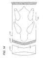
- FIG. 14 is a top plan view of the sealed bag.
- FIG. 15 is a top plan view of the sealed bag, shrunken to its final configuration.
- FIG. 16 is a top plan view of a rectangular product, such as a block of cheese, shown in a bag with a seal bar and cutoff blade shown in position for sealing and cutting off the bag.
- FIG. 17 is a top plan view thereof, showing the bag sealed.
- FIG. 18 a is a longitudinal cross-section of a modified embodiment bag sealing unit with a modified cutoff knife assembly.
- FIG. 18 b is a longitudinal cross-section thereof, showing the sealing bar and the cooling plates in their lowered, engaged positions.
- FIG. 18 c is a longitudinal cross-section section thereof, showing the vacuum cover raised and the bagged product being removed.
- FIG. 19 is a top plan view of a circular, carousel-type bag sealing system.
- FIG. 20 is a plan view of a bag sealing system comprising an alternative embodiment of the present invention.
- FIG. 21 is another plan view thereof, showing various stations corresponding to the steps of the bag sealing method of the present invention.
- FIG. 22 is a side elevational view thereof.
- FIG. 23 is an enlarged, fragmentary, side elevational view taken generally within circle 23 in FIG. 22 , and particularly showing a drive mechanism.
- FIG. 24 is an enlarged, vertical, cross-sectional view of a bag sealing unit, with a dome thereof in its raised position.
- FIG. 25 is an enlarged, vertical, cross-sectional view thereof, with the dome in its lowered position.
- FIG. 26 is an enlarged, vertical, cross-sectional view thereof, with the dome and a sealing assembly thereof in their lowered positions for sealing a bag neck.
- FIG. 27 is an enlarged, vertical, cross-sectional view thereof, showing the sealing bar slightly lifted above the bag neck.
- FIG. 28 is an enlarged, vertical, cross-sectional view thereof, showing the dome and the sealing assembly in their raised position, with the bag neck sealed.
- FIG. 29 is an enlarged, fragmentary view of a modified sealing assembly of another alternative embodiment of the present invention, with the cutoff blade thereof mounted on the outside face of a cooling bar.
- FIGS. 1 a and 1 b illustrate an automated multiple-chamber vacuum packaging machine 100 .
- the machine includes a continuous, driven chain or belt 101 supported on and driven by an idler roller 102 a and a drive roller 102 b .
- a circuitous train of lower vacuum platens 200 are fastened at their leading edges to the belt 101 .
- the platens 200 are made of stainless steel.
- the platens are moving counterclockwise in a direction from right to left across the top.
- the belt 101 is driven by sprocket and bearing assemblies that are fixed to a drive shaft and a free wheeling shaft (not shown).
- the drive shaft is driven by a servo drive gear reduction motor 110 .
- Three vacuum chambers 300 (individually denoted by numbers 300 a , 300 b and 300 c ) are mounted above the belt 101 .
- the platens 200 and respective vacuum chambers 300 collectively form respective bag sealing units 106 , which are capable of automated or semi-automated operation ( FIGS. 1 a, b ), or stand-alone operation as individual bag sealing units 106 .
- the vacuum packaging machine 100 operates as follows.
- the belt 101 moves counterclockwise (i.e., from right-to-left across the top). Movements can be continuous or intermittent, the latter being adapted for “batch”-type operations, thereby moving the lower vacuum platens 200 underneath the vacuum chambers 300 .
- the packaging machine 100 rate of output is generally governed by the number of vacuum chambers 300 usable simultaneously in operation, together with the duration of the process steps in each unit.
- each vacuum chamber 300 operates independently and simultaneously.
- the packaging machine 100 uses all available empty vacuum chambers 300 by means of sensors 224 that monitor various operating parameters, such as timing, temperature and pressure with respect to the vacuum chambers 300 and the bag sealing units 106 , the rate of chain 101 movement and availability of vacuum chambers 300 .
- a programmable microprocessor controller 222 can be connected to the sensors 224 and other components of the system 100 for controlling its operation, particularly in automated and semi-automated operating modes.
- each independent vacuum chamber 300 performs the following functions.
- the vacuum chamber cover 302 descends upon a vacuum platen 200 positioned directly below (see 300 a , FIG. 1 ).
- the vacuum chamber cover 302 forms a seal with the upper surface 202 of the vacuum platen by means of a seal gasket 304 (see FIGS. 2 a and 2 b ).
- Air within the sealed chamber 300 is then evacuated by means of an exhaust valve 306 located in the top surface of the cover 302 and connected to a suitable vacuum source, such as a compressor.
- a vacuum sensor (not shown) monitors the air pressure in the chamber 300 and reports the pressure value to the microprocessor controller 222 .
- An air pressure set point has been previously programmed into the microprocessor controller 222 .
- the microprocessor controller 222 triggers an air compressor (not shown) to inflate a bladder 308 located on the inner, upper surface of the cover 302 .
- the bladder 308 fills with compressed air, provided through bladder air supply line 318 , and expands downward, forcing the sealing bar assembly 310 downward ( FIG. 2 b ) and overcoming the return springs 384 .
- the sealing bar 350 is mounted on the lower extremity of the sealing bar assembly 310 .
- an item 104 to be vacuum sealed in this case a poultry carcass, has been placed inside a plastic vacuum seal bag 120 upon a cradle 204 located on the upper surface 202 of the vacuum platen 200 .
- the bag 120 is made of a thermoplastic film known in the industry for heat sealing and heat shrinking applications.
- the bag 120 is oriented so that the open neck 122 lies on top of a sealing support assembly 205 with spring-loaded engagement gaskets 206 a , 206 b and 206 c .
- the neck 122 is fitted over a set of neck retention pins 209 that hold the neck 122 of the bag open so that air may be drawn out of the bag 120 by the vacuum created in the chamber 300 .
- the sealing bar 350 After closing the cover 302 against the platen 200 and evacuating the air inside the chamber 300 to the pre-programmed set point, the sealing bar 350 is forced downward by the expanding inflatable bladder 308 , thereby coming into contact with the plastic of the neck 122 .
- the sealing bar 350 continues to move downward, overcoming the upward spring 216 bias of the engagement gaskets 206 a,b,c .
- As the sealing bar 350 moves downward the neck 122 is pushed against a fixed cutoff blade 124 .
- the neck 122 of the bag 120 is thereby sheared or cutoff by the cutoff blade 124 , which separates a neck cutoff portion 122 c .
- the device is calibrated so that downward motion of the sealing bar 350 ceases shortly after the neck 122 of the bag is driven against the cutoff blade 124 and severed.
- the sealing bar 350 includes a contact surface 354 , which contacts the plastic of the neck 122 , thus transferring thermal energy to the plastic film, melting the plastic and causing the upper wall 122 a and the lower wall 122 b to meld or fuse together, creating a thermocompressive bond at 122 d .
- two heat sink/cooling plates 360 a,b also come into contact with the surface of the neck 122 , one on either side of the sealing bar 350 , along their respective cooling plate lower edges 362 a,b .
- the cooling plates 360 a,b are attached to the seal bar assembly 310 , and are driven downward along with the sealing bar 350 by the force of the inflated bladder 308 .
- the heat sink/cooling plates 360 provide means for cooling the portion of the neck 122 proximate the area of contact between the sealing bar 350 and plastic film, thereby minimizing shrinkage of the neck 122 during heat sealing.
- the cooling plates 360 also serve to hold the neck 122 in position by clamping same against the engagement gaskets 206 a,c during the sealing operation.
- the three engagement or support gaskets 206 a,b,c are spring biased, so that they maintain upward pressure against the neck 122 while yielding to the downward force of the sealing bar 350 and the cooling plates 360 a,b .
- the cooling plates 360 a,b are also spring biased so that towards the end of the downward stroke of the sealing bar assembly 310 the sealing bar 350 may move past the cooling plates 360 a,b , driving further downward and causing the neck 122 to be cut against the bag cutoff blade 124 .
- the neck 122 of the bag 120 is held open during the sealing process by a pair of neck retention pins 209 a and 209 b .
- a side view of pin 209 b may be seen in FIGS. 2 a through 2 c.
- FIG. 2 b illustrates the downward travel of the sealing bar assembly 310 with arrows 313 a , 313 b and 313 c indicating the downward direction of travel.
- Arrow 314 indicates the direction of the final evacuation of air from the bag 120 , which is achieved just prior to incision of the neck 122 by the cutting blade 124 .
- Dashed line 120 a indicates the relative size of the bag 120 prior to the final expulsion of air which reduces it to the size indicated by the solid line 120 b .
- FIG. 2 b also illustrates the bladder 308 in its inflated state.
- the cradle 204 may be formed with a concave upper surface to receive an item 104 having a curved or rounded shape.
- FIG. 2 c illustrates the apparatus at the conclusion of a cycle, in which the cover 302 has been lifted off of the platen 200 .
- the sealed bag 120 is shown being removed from the cradle 204 .
- Arrow 315 indicates the upward direction of travel of the bag 120 as it is being removed. It should be appreciated that removal of the sealed bag 120 typically occurs after full retraction (lifting) of the cover 302 .
- Arrow 313 d indicates the upward direction of travel of the seal bar assembly 310 as it is retracted upwards by expulsion of air from the bladder 308 .
- Arrow 316 indicates the upward direction of travel of the cover 302 as it is raised above the platen 200 .
- FIG. 2 c the neck 122 is shown after being separated by the cutting blade 124 .
- the portion of the neck 122 remaining attached to the body of the bag 120 contains the sealed portion of the neck 122 d (see FIG. 14 for a top view of the sealed portion 122 d of the neck 122 ).
- the cut-off remnant 122 c of the neck 122 is ejected from the neck retention pins 209 , as shown by arrow 317 indicating the upward direction of travel, and phantom lines indicating the ejected neck remnant 122 c.
- FIG. 3 is a partial cross-sectional view along line 3 - 3 in FIG. 2 a .
- the cover 302 and the platen 200 are shown in cross section and the plastic bag 120 , the neck and in the in a and to the 122 and the pins 209 a,b are shown in phantom lines.
- the bladder 308 is located on the upper inside surface of the cover 302 and is in communication with an air supply hose 318 which is in further communication with an air pump or compressor (not shown).
- a seal bar assembly suspension 380 comprises spring biased bolts 382 that support the seal bar assembly 310 by attachment to the upper inside surface of the cover 302 .
- the springs 384 force the assembly 310 upward, squeezing against the bladder 308 when the assembly 310 is in the retracted position.
- the force exerted by the expanding bladder walls overcomes the tension of the springs 384 , causing the assembly 310 to slide downward along the shafts of the bolts 382 .
- a cooling plate suspension system 390 is also illustrated in FIG. 3 .
- the cooling plates 360 a,b are attached to the sealing bar assembly 310 via bolts 392 mounting return springs 394 .
- the tension in the springs 394 may be overcome by a greater force associated with the downward travel of the cooling plates 360 a,b.
- the elongated, convex side of the cooling plate 360 a is illustrated in FIG. 3 , including a notch 366 in the upper surface of the cooling plate 360 a which provides egress for electrical supply wiring 400 .
- the wiring 400 conducts a controlled current to the heating element 352 ( FIG. 5 ).
- the heating element 352 supplies thermal energy to the sealing bar 350 , which is thus maintained at a selected, relatively constant temperature.
- the thermal energy supplied to the sealing bar 350 is regulated by controlling the current applied to the heating element 352 through setting a desired temperature value in a microprocessor-controlled thermostat (not shown).
- Water inlet and outlet lines 370 , 372 lead to and from the cooling plates 360 a,b .
- cool water or other suitable coolant
- the temperatures of the surfaces of the cooling plates 360 a,b are thereby reduced, concurrently lowering the temperature of the portion of the plastic bag 120 contacted by the cooling plates 360 a,b during sealing.
- FIG. 4 a is a top plan view of the preferred embodiment of the neck retention structure 208 . It comprises a pair of pins 209 a and 209 b that extend outward from a neck retention bracket 210 that holds a guide tube 212 in which the pins 209 a,b are urged outwardly by respective springs 214 a,b .
- the pins 209 a,b travel along the guide tube 212 during operation of the device.
- the pins 209 a,b are compressed inwardly towards the center of the guide tube 212 . Releasing the pins 209 a,b stretches the bag opening to its full open, extended position for maximum effective sealing at 122 d.
- FIG. 4 b is an end view of the neck retention structure 208 , including a side view of neck retention pin 209 b.
- a motorized configuration with a screw-threaded rod driven by a suitable servo motor controlled by the microprocessor controller 222 can be provided and can reciprocate the neck retention pins 209 a,b inwardly and outwardly.
- FIG. 5 is an orthographic view of a curved sealing bar 350 with the cover plate removed to show the tubular heating element 352 that provides constant sealing temperature.
- FIG. 5 also shows the contact surface 354 of the sealing bar 350 designed to provide a cross-hatch pattern when melting the sealed plastic of a vacuum bag 120 .
- FIG. 6 is a bottom view of the sealing bar 350 showing the cross-hatch pattern in greater detail. This cross-hatch pattern permits the device to form a seal through contaminated plastic as well as through gathered layers of plastic created by irregularly shaped products. In particular, multiple, crisscrossed meld lines are formed and tend to cut across contaminated substances and gathered plastic layers, forming multiple barriers to leakage.
- FIG. 7 is an orthographic view of the sealing bar 350 of FIG. 5 with the cover plate 356 in place.
- FIG. 8 is an isometric view of the front of the sealing bar 350 with the top portion of the sealing bar tilted slightly toward the viewer.
- FIG. 9 is an orthographic view of a straight or linear sealing bar 350 with the cover plate 356 removed to show the straight tubular heating element 352 used to create a constant temperature heat source.
- the contact surface 354 of the sealing bar 350 shown in FIG. 9 has a cross-hatch pattern.
- FIG. 10 is an orthographic view of the sealing bar 350 of FIG. 9 with the cover plate 356 in place.
- FIG. 11 is an orthographic view of the sealing support assembly 205 including the engagement gaskets 206 a , 206 b and 206 c , and the bag cutoff blade 124 .
- a sealing support base 220 includes secondary channels 222 for receiving springs 224 , a primary major channel 226 a within which is mounted the cutoff blade 124 , and a secondary major channel 226 b which defines and separates engagement gaskets 206 b and 206 c .
- the gaskets 206 a , 206 b and 206 c fit over channels 222 and rest upon springs 224 .
- the gaskets 206 a , 206 b and 206 c may include a contact surface having a cross-hatched pattern. The arrangement shown in FIG. 11 would be appropriate for use with a curved sealing bar as shown in FIG. 7 .
- FIG. 12 is an upper, front, orthographic view of the vacuum chamber cover 300 .
- FIG. 13 is a fragmentary plan view of the bag 120 containing the item to be packaged 104 , the sealing bar 350 positioned above the neck 122 of the bag 120 , the cutting blade 124 , and a severed portion (remnant) 122 c of the neck 122 .
- FIG. 14 is a plan view of the bag 120 of FIG. 13 showing the neck remnant 122 c severed and removed from the main portion of the bag 120 and the seal 122 d formed across the neck 122 .
- a subsequent process occurs in the packaging process.
- the sealed bag 120 is deposited in a hot water bath or steam tunnel causing the thermoplastic material of the bag 120 to shrink as illustrated in FIG. 15 .
- FIG. 16 is a fragmentary plan view of an alternative configuration sealing bar 350 .
- the sealing bar 350 is straight rather than curved as is the cutoff blade 124 .
- the embodiment shown in FIG. 16 is advantageous for use with rectangular shaped items, such as the cheese block shown.
- FIG. 17 is a top view of the bag 120 of FIG. 16 with a portion of the neck 122 removed after vacuum sealing and with the bag 120 shrunk after hot water immersion.
- FIGS. 18 a - c illustrate an alternative embodiment of the vacuum packaging machine 500 .
- the illustrated embodiment differs from that illustrated in FIGS. 2 a through 2 c primarily in that the engagement gaskets 506 a,b are fixed rather than spring-biased.
- the cutoff blade 524 is movable rather than fixed and is mounted on a cutoff blade platform 526 mounted on bolts 528 with springs 529 biasing the cutoff blade platform 526 downwardly.
- the platform 526 and the associated cutting blade 524 are moved upward during the cutting operation by means of a secondary bladder 528 .
- Air supply to the secondary bladder 528 is regulated by a three-way valve 530 .
- the valve 530 is activated by a pin 534 .
- the pin 534 is depressed by the descending cooling plate 560 b .
- the pin 534 moves downward through the platform 526 and activates the valve 530 causing the bladder 528 to be opened to ambient air pressure outside the vacuum chamber 500 through a vent opening 531 formed in the platen 600 .
- the secondary bladder 528 fills with outside air, pushing the platform 526 and the cutoff blade 524 upward, and severing the neck 122 of the bag 120 as shown in FIG. 18 b.
- FIG. 18 c illustrates the vacuum packaging machine 500 at the conclusion of the cycle.
- the cover 502 has been lifted off the platen 600 and the sealed bag 120 is shown being removed from the cradle 604 .
- Arrow 615 indicates the upward direction of travel of the bag 120 as it is being removed.
- FIG. 19 shows an alternative configuration rotary chamber system 700 comprising a circular conveyor 702 with multiple bag sealing units 106 mounted thereon in radially-spaced relation.
- the conveyor 702 is rotated by a motor whereby the bag sealing units 106 perform sealing operations at appropriate workstations for different steps of the process.
- the components of the system 100 are preferably constructed of suitable materials, such as stainless-steel or aluminum, which can accommodate power washing for cleaning purposes and tend to resist rust and corrosion in working environments with relatively high humidity and temperature levels.
- FIGS. 20-27 Another alternative embodiment bag sealing system is shown in FIGS. 20-27 and is generally designated by the reference numeral 1002 .
- the system 1002 generally includes a conveyor subsystem 1004 , which comprises a platen conveyor 1006 with a plan configuration defining a platen travel path generally in the shape of a racetrack or a rounded oblong, and a carousel-type dome conveyor 1008 .
- the dome conveyor 1008 has a generally circular plan configuration defining a circular dome travel path, which is generally located in a horizontal plane above the level of a horizontal plane generally containing the platen conveyor 1006 .
- the platen conveyor 1006 mounts a number of platens 1010 , which selectively receive respective domes 1012 suspended from the dome conveyor 1008 whereby bag sealing units 1014 are combined temporarily through vacuum and sealing stations 1016 , 1018 ( FIG. 21 ).
- the platen conveyor 1006 also includes loading and discharge stations 1020 , 1022 .
- the dome conveyor 1008 also includes a dome-up station 1024 .
- the bag sealing units 1014 are combined through the vacuum and sealing stations 1016 , 1018 , and separate into disconnected platens 1010 and domes 1012 through the other conveyor stations.
- the platens 1010 are rollingy placed on tracks 1026 on the platen conveyor 1006 .
- an unsealed bag 1028 containing an object 1030 is placed on each platen 1010 .
- the loading station 1020 can be supplied with a suitable supply conveyor (not shown) for automatic loading of the platens 1010 , or the bagged objects 1030 can be placed thereon manually.
- the loaded platens 1010 next proceed towards the dome carousel 1008 and into alignment underneath respective domes 1012 .
- the platen conveyor 1006 passes beneath the dome conveyor 1008 at approximately the location where the vacuum station 1016 commences.
- the bags 1028 are evacuated through the vacuum station 1016 , as described above.
- the bags 1028 are sealed and the bag sealing units 1014 proceed to the ventilation station 1018 whereat the domes 1012 are ventilated and lifted from the platens 1010 .
- the platens 1010 next proceed to the discharge station 1022 whereat the sealed items can be discharged by any suitable mechanism, including without limitation manual, semi automatic and automatic.
- the rails 1026 of the platen conveyor 1006 deflect upwardly at 1032 and thereby tilt the platens 1010 for sloping downwardly and outwardly and discharging the bagged items therefrom at the discharge station 1022 .
- a drive mechanism 1034 is shown in FIG. 23 and generally includes a drive motor and gearbox 1036 driving a main drive shaft or live axle 1038 through a belt drive assembly 1040 .
- the carousel-configuration in dome conveyor 1008 is supported by multiple casters 1042 , whereby the dome conveyor 1008 rotates about a drive axis extending through the main drive shaft 1038 .
- Each platen 1010 includes a base 1040 with an upper surface 1042 mounting an item support 1044 adapted to receive a bagged items 1030 and a neck support 1046 adapted to receive necks 1048 of respective bags 1028 .
- the neck support 1046 includes a resilient contact service 1050 , which can be mounted on springs are comprises a compressible material in order to provide resiliency.
- a ridge 1052 is located on top of the contact surface 1050 .
- Each dome 1012 includes a top 1060 , a perimeter sidewall 1062 with a lower edge 1064 mounting a perimeter sealing gasket 1066 adapted for forming a sealing engagement with the base upper surface 1042 .
- a sealing assembly 1068 is mounted on the underside of the top 1060 generally within a vacuum chamber 1070 formed by the dome 1012 .
- the sealing assembly 1068 includes a pneumatic raise/lower actuating mechanism 1072 with a bladder 1074 connected to an air inlet port 1076 , which in turn can be connected to a pressurized air source 1078 , such as a compressor or a packaging plant air source.
- the actuating mechanism 1072 includes a seal bar 1082 adapted for constant high-temperature operation, e.g. with nichrome electrical resistance heating elements, as described above. Without limitation on the generality of useful heat sources, other types such as circulating liquid, combustion, resistance heating, infrared, etc. could be provided.
- the seal bar 1082 mounts a cut-off blade 1084 , which protrudes slightly below a lower contact surface 1086 of the seal bar 1082 .
- the seal bar 1082 is located between a pair of heat-sink cooling bars 1088 , each of which includes coolant passages for receiving and circulating coolant, which enters and exits through cooling bar coolant ports 1090 connected to sealing assembly coolant inlet ports 1092 .
- the cooling bars 1088 are biased downwardly by compression springs 1094 , which compress the bag neck 1048 against the gasket 1050 for sealing. As shown in FIG. 24 , the cooling bars 1088 normally extend below the level of the seal bar lower contact surface 1086 , whereby they function as heat sinks absorbing the heat generated by the seal bar 1082 .
- the entire sealing assembly 1068 is thus maintained at a relatively low temperature.
- the seal bar 1082 can be maintained at a constant temperature because exposure to the plastic bag neck 1048 only occurs in the sealing position, with the seal bar 1082 at its lowermost position relative to the cooling bars 1088 ( FIG. 26 ). In this position, which corresponds to the activation of the sealing process at station 1017 , the seal bar lower contact surface 1086 is in close proximity to the compressed double plastic layers forming the bag neck 1048 , which are thermally welded and sealed.
- the cut-off blade 1084 separates a neck cut-off portion 1049 , which can be discarded.
- the seal bar 1082 is then slightly raised to the position shown in FIG. 27 , with its lower contact surface 1086 position slightly above the bag neck 1048 whereby the welded seam 1087 is allowed to cool or set, generally for about 0.1 to about 0.5 seconds.
- the process is completed by retracting the actuating mechanism 1072 to its fully-raised position ( FIG. 28 ).
- the dome 1008 is lifted from the platen 1006 and the latter, with the vacuum-packaged product 1030 thereon, proceeds to the discharge station 1022 .
- Various additional steps and processes can be included in the method of the present invention and performed with appropriate modifications to the system of the present invention. For example, in food-handling operations certain procedures may be needed in order to maintain sanitary conditions. These can include washing and otherwise cleaning and sterilizing the equipment, which can comprise stainless steel or other suitable construction with desired characteristics such as resistance to rust and corrosion. Moreover, additional operations can be performed on the packaged products, such as weighing, labeling, additional packaging, freezing, drying, cooking, etc.
- a suitable control system 1096 which can include a microprocessor 1098 , can be provided and located in a control system and enclosure 1100 with a touch screen display 1102 mounted on a door 1104 of the enclosure 1100 .
- the control system can include various sensors, which can be connected to its inputs, for monitoring and interactively controlling the operation of the system 1002 . Operation of the various system components can be controlled by outputs from the control system 1096 , such as speed and load control for the drive motor 1036 , temperature control for the sealing bar 1082 , and coolant circulation pump control.
- the bag sealing system 1002 is suited for operation in an automated plant, whereby the product supply, loading, discharge and packaging procedures can be automated.
- the control system 1096 is also connected to an electrical power source 1095 powering the seal bars 1082 , a vacuum source 1097 for controlling the selective application of vacuum to the vacuum chambers 1070 , the pressurized air source 1078 for controlling the selective application of pressurized air through the air inlet ports 1076 and a coolant source 1099 for controlling the selective application of coolant through the coolant inlet ports 1090 .
- Vacuum, pressurized air and coolant are distributed from their respective sources 1097 , 1078 and 1099 through a rotary manifold distribution mechanism 1093 to the domes 1012 .
- a modified sealing assembly 1106 of another alternative embodiment of the present invention is shown in FIG. 29 and includes the cut-off blade 1084 mounted on the outside of the cooling bar 1088 .
- any cutoff portion 1049 of the neck 1048 would occur further away from the seam 1087 , whereby less or possibly no waste or scrap material is produced from each bag 1028 .
- the cut-off blade 1084 can be eliminated altogether, or deactivated by raising it to an inoperative position on the sealing assembly, whereby no waste or scrap bag material is produced in the sealing operation and the original neck is simply left in its original, full-length configuration.
Abstract
Description
Claims (9)
Priority Applications (4)
| Application Number | Priority Date | Filing Date | Title |
|---|---|---|---|
| US11/073,559 US7328556B2 (en) | 2003-01-16 | 2005-03-07 | Bag sealing system and method |
| US12/030,049 US20080127614A1 (en) | 2003-01-16 | 2008-02-12 | Bag sealing system and method |
| US12/400,290 US20090173436A1 (en) | 2003-01-16 | 2009-03-09 | Bag sealing system and method |
| US13/032,458 US8069637B2 (en) | 2003-01-16 | 2011-02-22 | Bag sealing system and method |
Applications Claiming Priority (2)
| Application Number | Priority Date | Filing Date | Title |
|---|---|---|---|
| US10/345,763 US6862867B2 (en) | 2003-01-16 | 2003-01-16 | Bag sealing system and method |
| US11/073,559 US7328556B2 (en) | 2003-01-16 | 2005-03-07 | Bag sealing system and method |
Related Parent Applications (1)
| Application Number | Title | Priority Date | Filing Date |
|---|---|---|---|
| US10/345,763 Continuation-In-Part US6862867B2 (en) | 2003-01-16 | 2003-01-16 | Bag sealing system and method |
Related Child Applications (2)
| Application Number | Title | Priority Date | Filing Date |
|---|---|---|---|
| US12/030,049 Continuation US20080127614A1 (en) | 2003-01-16 | 2008-02-12 | Bag sealing system and method |
| US12/030,049 Continuation-In-Part US20080127614A1 (en) | 2003-01-16 | 2008-02-12 | Bag sealing system and method |
Publications (2)
| Publication Number | Publication Date |
|---|---|
| US20050150195A1 US20050150195A1 (en) | 2005-07-14 |
| US7328556B2 true US7328556B2 (en) | 2008-02-12 |
Family
ID=32711998
Family Applications (5)
| Application Number | Title | Priority Date | Filing Date |
|---|---|---|---|
| US10/345,763 Expired - Lifetime US6862867B2 (en) | 2003-01-16 | 2003-01-16 | Bag sealing system and method |
| US11/073,559 Expired - Lifetime US7328556B2 (en) | 2003-01-16 | 2005-03-07 | Bag sealing system and method |
| US12/030,049 Abandoned US20080127614A1 (en) | 2003-01-16 | 2008-02-12 | Bag sealing system and method |
| US12/400,290 Abandoned US20090173436A1 (en) | 2003-01-16 | 2009-03-09 | Bag sealing system and method |
| US13/032,458 Expired - Lifetime US8069637B2 (en) | 2003-01-16 | 2011-02-22 | Bag sealing system and method |
Family Applications Before (1)
| Application Number | Title | Priority Date | Filing Date |
|---|---|---|---|
| US10/345,763 Expired - Lifetime US6862867B2 (en) | 2003-01-16 | 2003-01-16 | Bag sealing system and method |
Family Applications After (3)
| Application Number | Title | Priority Date | Filing Date |
|---|---|---|---|
| US12/030,049 Abandoned US20080127614A1 (en) | 2003-01-16 | 2008-02-12 | Bag sealing system and method |
| US12/400,290 Abandoned US20090173436A1 (en) | 2003-01-16 | 2009-03-09 | Bag sealing system and method |
| US13/032,458 Expired - Lifetime US8069637B2 (en) | 2003-01-16 | 2011-02-22 | Bag sealing system and method |
Country Status (7)
| Country | Link |
|---|---|
| US (5) | US6862867B2 (en) |
| EP (1) | EP1611013B1 (en) |
| AT (1) | ATE514629T1 (en) |
| AU (1) | AU2004206028B2 (en) |
| CA (1) | CA2528780C (en) |
| NZ (1) | NZ541567A (en) |
| WO (1) | WO2004065091A2 (en) |
Cited By (8)
| Publication number | Priority date | Publication date | Assignee | Title |
|---|---|---|---|---|
| US20090173436A1 (en) * | 2003-01-16 | 2009-07-09 | Taylor Sr Mark W | Bag sealing system and method |
| US8088646B1 (en) * | 2006-09-12 | 2012-01-03 | Maxim Integrated Products, Inc. | Check valve package for PB-free, single piece electronic modules |
| US20120110956A1 (en) * | 2010-10-13 | 2012-05-10 | Multivac Sepp Haggenmueller Gmbh & Co. Kg | Method and chamber machine for sealing packaging material |
| US20140123599A1 (en) * | 2011-07-12 | 2014-05-08 | Thomas Gustafsson | Packaging apparatus and method of expelling gas |
| US20140360134A1 (en) * | 2013-06-11 | 2014-12-11 | Cryovac, Inc. | Ferris-Wheel Type Vacuum Packaging System And Method |
| US20170050754A1 (en) * | 2015-08-17 | 2017-02-23 | Sf Investments, Inc. | Vacuum Packing Monitoring and Control System |
| US11136154B2 (en) | 2017-09-22 | 2021-10-05 | Atlanta Attachment Company | Packaging machine for bedding products |
| US11565844B2 (en) | 2018-12-21 | 2023-01-31 | S.C. Johnson & Son, Inc. | Methods and apparatus to facilitate plastic film processing |
Families Citing this family (62)
| Publication number | Priority date | Publication date | Assignee | Title |
|---|---|---|---|---|
| AU2002343060A1 (en) * | 2001-11-23 | 2003-06-10 | De La Rue International Limited | Verification method and apparatus |
| US7021027B2 (en) * | 2003-07-29 | 2006-04-04 | Tilia International, Inc. | Vacuum pump control and vacuum feedback |
| WO2005108210A1 (en) * | 2004-05-06 | 2005-11-17 | Cp Packaging, Inc. | Linear motion vacuum packaging system |
| ITTV20040092A1 (en) * | 2004-08-05 | 2004-11-05 | Ala 2000 S P A | DEVICE FOR SEALING OF BAGS UNDER VACUUM. |
| US7331161B2 (en) * | 2004-11-05 | 2008-02-19 | Cp Packaging, Inc. | Combination vacuum manifold and support beam for a vacuum packaging system |
| US7575114B2 (en) | 2004-11-05 | 2009-08-18 | Cp Packaging, Inc. | Conveyor belt construction for a platen-type conveyor |
| US20060096250A1 (en) * | 2004-11-05 | 2006-05-11 | Rennco, Inc. | Packaging device and method |
| US9505191B2 (en) | 2005-12-13 | 2016-11-29 | Delta Industrial Services, Inc. | Reciprocating sealer for web converters |
| US7497065B2 (en) * | 2005-12-13 | 2009-03-03 | Delta Industrial Services, Inc. | Reciprocating sealer for web converters |
| US7726104B2 (en) * | 2006-06-21 | 2010-06-01 | Cp Packaging, Inc. | Vacuum packaging system with end cutter |
| ITVR20060181A1 (en) * | 2006-11-24 | 2008-05-25 | Marziano Salvaro | EQUIPMENT FOR VACUUM PACKAGING OF FOOD PRODUCTS |
| DE102007020392A1 (en) * | 2007-04-30 | 2008-11-06 | Multivac Sepp Haggenmüller Gmbh & Co. Kg | Apparatus and method for displaying measured values and shrink tunnels for a packaging machine or packaging machine with such a device |
| US7967509B2 (en) | 2007-06-15 | 2011-06-28 | S.C. Johnson & Son, Inc. | Pouch with a valve |
| US7874731B2 (en) | 2007-06-15 | 2011-01-25 | S.C. Johnson Home Storage, Inc. | Valve for a recloseable container |
| DE102008015692A1 (en) | 2008-03-26 | 2009-10-29 | Multivac Sepp Haggenmüller Gmbh & Co. Kg | Method and device for packaging products in bags |
| KR101070590B1 (en) | 2009-06-25 | 2011-10-10 | (주) 가성팩 | Cooling system for sealing bar of vacuum packing machine |
| DK2322340T3 (en) * | 2009-11-17 | 2019-06-11 | Seelen As | Process for the accumulation of foil during a welding process |
| CN101817408B (en) * | 2010-04-09 | 2011-11-09 | 叶春林 | Thermal sealing package method and assembly of plastic films |
| US20120186199A1 (en) * | 2010-09-21 | 2012-07-26 | Crane Payment Solutions Inc. | Validator and bill stacker configured to store notes in sealing, tamper-evident bags within a cash management safe |
| KR101439328B1 (en) * | 2011-05-25 | 2014-09-17 | 주식회사 인트로팩 | Vacuum packing apparatus |
| US9656774B2 (en) * | 2011-06-15 | 2017-05-23 | Tetra Laval Holdings & Finance S.A. | Suspension for a sealing jaw and method for calibrating sealing jaws |
| JP5575827B2 (en) * | 2012-03-27 | 2014-08-20 | 株式会社Tosei | Vacuum packaging method and vacuum packaging apparatus |
| US9745087B2 (en) * | 2013-01-04 | 2017-08-29 | Tama Plastic Industry | Method and apparatus for securing baled items |
| US9623989B2 (en) * | 2013-03-01 | 2017-04-18 | The Procter & Gamble Company | Method and apparatus for bundling packages of absorbent articles |
| US11440693B2 (en) * | 2013-03-13 | 2022-09-13 | Mars, Incorporated | Manufacturing process for packaged pet food |
| CN103241413B (en) * | 2013-05-07 | 2015-08-26 | 中山环亚塑料包装有限公司 | A kind of heat-sealing membrane cutting knife device |
| DE102013105601B4 (en) * | 2013-05-31 | 2017-12-14 | Windmöller & Hölscher Kg | Floor sealing station for the production of a bottom seam |
| EP2886303A1 (en) * | 2013-12-20 | 2015-06-24 | Multivac Sepp Haggenmüller GmbH & Co. KG | Sealing rail comprising a heat pipe for a packaging machine |
| EP2942299B1 (en) * | 2014-05-05 | 2019-08-28 | MULTIVAC Sepp Haggenmüller SE & Co. KG | Packing unit with a controllable temperature and method for same |
| US10029407B2 (en) | 2014-12-04 | 2018-07-24 | Big Heart Pet, Inc. | Apparatus, processes, and systems for heat sealing |
| CN104670571A (en) * | 2015-02-11 | 2015-06-03 | 邵武市天福包装彩印有限公司 | Plastic film sealing device |
| CH709372B1 (en) * | 2015-07-10 | 2023-12-15 | V Zug Ag | Vacuum sealer with container support. |
| KR20170026230A (en) * | 2015-08-27 | 2017-03-08 | 주식회사 엘지화학 | apparatus for sealing secondary battery |
| CN108602572B (en) | 2015-09-25 | 2021-09-21 | 克里奥瓦克公司 | Apparatus and method for evacuating and sealing packages |
| NZ741259A (en) * | 2015-11-10 | 2022-02-25 | Cryovac Llc | Apparatus and process for evacuation of packages |
| EP3168032B1 (en) | 2015-11-13 | 2019-02-27 | Fraunhofer Gesellschaft zur Förderung der Angewand | Joining device and joining method |
| CN108368913B (en) * | 2015-12-03 | 2020-11-17 | 弹性钢接头公司 | Tape splicing apparatus and method |
| US10155600B2 (en) * | 2015-12-28 | 2018-12-18 | Starvac Systems Pty Ltd | Apparatus for vacuum sealing products |
| WO2018071415A1 (en) * | 2016-10-10 | 2018-04-19 | Purdue Research Foundation | Continuous roll-to-roll freeze-drying system and process |
| US11034474B2 (en) * | 2016-10-31 | 2021-06-15 | Ross Industries, Inc. | Dual purpose seal head assembly, tray sealing system, and method therefor |
| CN106379606B (en) * | 2016-11-25 | 2018-11-02 | 华文食品股份有限公司 | A kind of dried bean curd packaging bag sealing device special |
| IT201600129875A1 (en) * | 2016-12-22 | 2018-06-22 | Altopack Spa | Head welding and cutting apparatus for food bags. |
| GB2566476B (en) | 2017-09-14 | 2020-01-01 | Fokker Aerostructures Bv | Conduction welding |
| US11262130B1 (en) * | 2017-12-14 | 2022-03-01 | Kolorfusion International Inc. | System and method for heat and pressure treatment |
| JP7131608B2 (en) * | 2018-04-18 | 2022-09-06 | 三菱マテリアル株式会社 | Polycrystalline silicon packaging method, polycrystalline silicon double packaging method, and single crystal silicon raw material manufacturing method |
| CN108408124A (en) * | 2018-04-18 | 2018-08-17 | 威海威高血液净化制品有限公司 | A kind of blood processor packing method and packaging facilities |
| ES2872970T3 (en) * | 2018-04-27 | 2021-11-03 | Multivac Haggenmueller Kg | Heated Rack Packaging Machine |
| CN108557179A (en) * | 2018-06-11 | 2018-09-21 | 重庆市飞龙种业有限责任公司 | Seed packaging bag sealer |
| JP7023805B2 (en) * | 2018-06-26 | 2022-02-22 | Pacraft株式会社 | Vacuum packaging machine and vacuum packaging method |
| PT3599452T (en) * | 2018-07-27 | 2020-12-23 | Ulma Packaging Tech Ct Coop | Packaging method and machine |
| US20200087012A1 (en) * | 2018-09-19 | 2020-03-19 | Tony Triet Nguyen | Method and apparatus to perform quick vacuum evacuation from universal sealable vacuum containers or wine bottles |
| CN110949783B (en) * | 2019-12-09 | 2021-05-04 | 湖南亲零嘴食品有限公司 | Meat is cooked and is eaten vacuum packaging and seal fixed compaction preprocessing device |
| CN111284751B (en) * | 2020-03-21 | 2020-12-22 | 开平市浩旺佳蛋制品有限公司 | Vacuum packaging equipment for fast food and vacuum packaging method thereof |
| CN112124701A (en) * | 2020-09-14 | 2020-12-25 | 湖南聚味堂食品有限公司 | Good heat dissipation's food machine |
| CN112373840B (en) * | 2020-11-05 | 2022-06-14 | 天津中环领先材料技术有限公司 | 12-inch silicon wafer packaging process |
| US11542050B2 (en) * | 2021-02-08 | 2023-01-03 | Bonsen Electronics Limited | Vacuum sealing machine driven by air pressure |
| CN113277173B (en) * | 2021-06-01 | 2022-10-14 | 山东欣悦健康科技有限公司 | Traditional chinese medicine powder encapsulation equipment |
| WO2022271186A1 (en) * | 2021-06-25 | 2022-12-29 | Thrivo Technologies Inc. | Systems and Methods of Preserving Customized Cosmetic Products |
| CN114074777B (en) * | 2021-11-18 | 2022-11-22 | 湖南亲零嘴食品有限公司 | Supplementary quick carminative vacuum packaging machine for instant duck neck of extrusion |
| KR20230147176A (en) * | 2021-12-13 | 2023-10-20 | 와커 헤미 아게 | Method and system for automatically packaging crushed silicon |
| CN115108088B (en) * | 2022-07-18 | 2023-12-08 | 江苏理工学院 | Integrated high-speed three-dimensional vacuum packaging machine |
| CN116674804B (en) * | 2023-06-16 | 2024-03-15 | 山东鸿毅食品有限公司 | Full-automatic vacuum packaging machine for processing instant food |
Citations (43)
| Publication number | Priority date | Publication date | Assignee | Title |
|---|---|---|---|---|
| US2913863A (en) | 1958-03-19 | 1959-11-24 | Amsco Packaging Machinery Inc | Machine for forming edge seal closures on bags |
| US3597897A (en) | 1969-10-21 | 1971-08-10 | Grace W R & Co | Method of and apparatus for vacuum sealing packs |
| US3699742A (en) | 1971-02-18 | 1972-10-24 | Grace W R & Co | Apparatus for vacuum welding of plastics envelopes |
| US3775225A (en) | 1971-07-06 | 1973-11-27 | Gloucester Eng Co Inc | Machine for perforating and heat sealing a web including an elongated element with a multiplicity of drivers |
| US3779838A (en) | 1971-11-12 | 1973-12-18 | Fmc Corp | Heat sealing head |
| US3832824A (en) | 1973-06-29 | 1974-09-03 | Grace W R & Co | Apparatus and method for evacuating packages |
| US3958391A (en) | 1974-11-21 | 1976-05-25 | Kabushiki Kaisha Furukawa Seisakusho | Vacuum packaging method and apparatus |
| US4164111A (en) | 1976-11-19 | 1979-08-14 | Pietro Di Bernardo | Vacuum-packing method and apparatus |
| US4221101A (en) | 1979-02-12 | 1980-09-09 | Fmc Corporation | Apparatus for evacuating and sealing bags |
| US4550548A (en) | 1983-05-26 | 1985-11-05 | W. R. Grace & Co., Cryovac Div. | Method and apparatus for vacuum packaging with preshrinking |
| US4578928A (en) | 1983-07-06 | 1986-04-01 | Acraloc Corporation | High speed evacuation chamber packaging machine and method |
| US4583347A (en) | 1982-10-07 | 1986-04-22 | W. R. Grace & Co., Cryovac Div. | Vacuum packaging apparatus and process |
| US4601159A (en) | 1984-09-14 | 1986-07-22 | W. R. Grace & Co., Cryovac Div. | Form-fill-seal machine and method with capability for providing a vacuum or inert gas atmosphere within the package |
| US4640081A (en) | 1981-05-23 | 1987-02-03 | Kabushiki Kaisha Furukawa Seisakusho | Automatic packaging apparatus |
| US4754596A (en) * | 1986-01-30 | 1988-07-05 | Furukawa Mfg. Co., Ltd. | Vacuum packaging method and apparatus |
| US4798039A (en) | 1985-12-05 | 1989-01-17 | Ipatec S.A. | Process and apparatus for filling containers under vacuum |
| US4843796A (en) | 1988-03-22 | 1989-07-04 | Ecs Corporation | Method and apparatus for vacuum packaging |
| US4845927A (en) | 1987-01-21 | 1989-07-11 | I.C.A. S.P.A. | Packaging machine having individual controlled atmosphere chamber means for each package |
| US4860523A (en) | 1986-10-31 | 1989-08-29 | Sharp Kabushiki Kaisha | Hermetic packaging apparatus |
| US4903459A (en) * | 1986-05-29 | 1990-02-27 | Furukawa Mfg. Co., Ltd. | Method and apparatus for discharging vacuum packaged goods from vacuum packaging apparatus |
| US4926614A (en) | 1986-11-05 | 1990-05-22 | Rmf Steel Products Co. | Packaging method and apparatus |
| US5056292A (en) | 1989-05-18 | 1991-10-15 | Multivac Sepp Haggenmuller Kg | Vacuum chamber packaging machine |
| US5062252A (en) | 1990-08-08 | 1991-11-05 | Viskase Corporation | Vacuum packaging method and apparatus |
| US5097648A (en) | 1990-04-26 | 1992-03-24 | Robert Bosch Gmbh | Apparatus for evacuating and closing bag package |
| US5131213A (en) | 1991-03-06 | 1992-07-21 | Shanklin Corporation | Sealing jaws |
| US5282349A (en) * | 1991-07-02 | 1994-02-01 | Weldotron Of Delaware, Inc. | Sealing and packaging method and apparatus |
| US5351463A (en) | 1991-11-07 | 1994-10-04 | Sara Lee/De N.V. | Method and apparatus for making a filled and closed vacuum pak |
| US5371998A (en) | 1993-01-13 | 1994-12-13 | W. R. Grace & Co.-Conn. | Modified atmosphere packaging device |
| US5386678A (en) | 1993-07-12 | 1995-02-07 | Furukawa Mfg. Co., Ltd. | Method and apparatus for vacuum packaging |
| US5435114A (en) | 1993-08-18 | 1995-07-25 | W. R. Grace & Co.-Conn | Automated packaging machine and packaging method |
| US5438883A (en) | 1992-05-11 | 1995-08-08 | Reynolds Metals Company | Computer controlled heat-sealing machine |
| US5528880A (en) | 1992-05-15 | 1996-06-25 | Inauen Maschinen Ag | Process for the packaging of product under vacuum and vacuum-packaging machine |
| US5640081A (en) | 1994-05-13 | 1997-06-17 | Apple Computer, Inc. | Method and apparatus for monitoring discharge of a battery device based on battery self-discharge and discharge over time |
| US5638664A (en) | 1995-07-17 | 1997-06-17 | Hantover, Inc. | Vacuum packaging apparatus |
| US5682727A (en) | 1996-05-03 | 1997-11-04 | Koch Supplies, Inc. | Coupled cutting blade and heat element for use with vacuum packaging machinery |
| US5692360A (en) | 1995-01-13 | 1997-12-02 | W. R. Grace & Co.-Conn. | System and method for packaging products |
| US5784862A (en) | 1995-01-27 | 1998-07-28 | Germano; Maina | Device for the packing under vacuum of products contained in flexible bags |
| US5822956A (en) | 1994-05-03 | 1998-10-20 | Inauen Maschinen Ag | Vacuum packaging machine |
| US5893822A (en) | 1997-10-22 | 1999-04-13 | Keystone Mfg. Co., Inc. | System for vacuum evacuation and sealing of plastic bags |
| US6324818B1 (en) | 1999-02-17 | 2001-12-04 | Slidell, Inc. | Vacuum filling machine for bags |
| US6539689B1 (en) * | 1999-08-02 | 2003-04-01 | Furukawa Mfg. Co., Ltd. | Bag mouth sealing device |
| US20040060262A1 (en) | 2002-09-27 | 2004-04-01 | Harges Steven Daniel | Vacuum packaging machine |
| US6862867B2 (en) * | 2003-01-16 | 2005-03-08 | Pack-Tech, L.L.C. | Bag sealing system and method |
Family Cites Families (10)
| Publication number | Priority date | Publication date | Assignee | Title |
|---|---|---|---|---|
| US60262A (en) * | 1866-12-04 | Cyrus w | ||
| US2433176A (en) * | 1944-10-18 | 1947-12-23 | Thompson Prod Inc | Sealing machine |
| US2651350A (en) * | 1947-11-26 | 1953-09-08 | Dewey And Almy Chem Comp | Packaging machine |
| US3818574A (en) * | 1970-12-14 | 1974-06-25 | Grace W R & Co | Closing system for bags and the like |
| US3693314A (en) * | 1970-12-14 | 1972-09-26 | Grace W R & Co | Closing system for bags and the like |
| US3799838A (en) * | 1971-07-15 | 1974-03-26 | Gen Electric | Cleaner and primer composition for metal surfaces |
| SE351592C (en) | 1972-03-29 | 1974-04-25 | Iwema Foerpacknings Ab | Welding jaws for welding foil webs together |
| JPS602413A (en) * | 1983-06-09 | 1985-01-08 | 株式会社古川製作所 | Rotary vacuum packer |
| US4580393A (en) * | 1984-04-11 | 1986-04-08 | Furukawa Mfg. Co., Ltd. | Packing apparatus |
| US5209042A (en) * | 1992-10-02 | 1993-05-11 | Rickard James H | String packaging apparatus and method |
-
2003
- 2003-01-16 US US10/345,763 patent/US6862867B2/en not_active Expired - Lifetime
-
2004
- 2004-01-13 AT AT04701778T patent/ATE514629T1/en not_active IP Right Cessation
- 2004-01-13 AU AU2004206028A patent/AU2004206028B2/en not_active Expired
- 2004-01-13 CA CA002528780A patent/CA2528780C/en not_active Expired - Lifetime
- 2004-01-13 WO PCT/US2004/000716 patent/WO2004065091A2/en active Application Filing
- 2004-01-13 EP EP04701778A patent/EP1611013B1/en not_active Expired - Lifetime
- 2004-01-13 NZ NZ541567A patent/NZ541567A/en not_active IP Right Cessation
-
2005
- 2005-03-07 US US11/073,559 patent/US7328556B2/en not_active Expired - Lifetime
-
2008
- 2008-02-12 US US12/030,049 patent/US20080127614A1/en not_active Abandoned
-
2009
- 2009-03-09 US US12/400,290 patent/US20090173436A1/en not_active Abandoned
-
2011
- 2011-02-22 US US13/032,458 patent/US8069637B2/en not_active Expired - Lifetime
Patent Citations (43)
| Publication number | Priority date | Publication date | Assignee | Title |
|---|---|---|---|---|
| US2913863A (en) | 1958-03-19 | 1959-11-24 | Amsco Packaging Machinery Inc | Machine for forming edge seal closures on bags |
| US3597897A (en) | 1969-10-21 | 1971-08-10 | Grace W R & Co | Method of and apparatus for vacuum sealing packs |
| US3699742A (en) | 1971-02-18 | 1972-10-24 | Grace W R & Co | Apparatus for vacuum welding of plastics envelopes |
| US3775225A (en) | 1971-07-06 | 1973-11-27 | Gloucester Eng Co Inc | Machine for perforating and heat sealing a web including an elongated element with a multiplicity of drivers |
| US3779838A (en) | 1971-11-12 | 1973-12-18 | Fmc Corp | Heat sealing head |
| US3832824A (en) | 1973-06-29 | 1974-09-03 | Grace W R & Co | Apparatus and method for evacuating packages |
| US3958391A (en) | 1974-11-21 | 1976-05-25 | Kabushiki Kaisha Furukawa Seisakusho | Vacuum packaging method and apparatus |
| US4164111A (en) | 1976-11-19 | 1979-08-14 | Pietro Di Bernardo | Vacuum-packing method and apparatus |
| US4221101A (en) | 1979-02-12 | 1980-09-09 | Fmc Corporation | Apparatus for evacuating and sealing bags |
| US4640081A (en) | 1981-05-23 | 1987-02-03 | Kabushiki Kaisha Furukawa Seisakusho | Automatic packaging apparatus |
| US4583347A (en) | 1982-10-07 | 1986-04-22 | W. R. Grace & Co., Cryovac Div. | Vacuum packaging apparatus and process |
| US4550548A (en) | 1983-05-26 | 1985-11-05 | W. R. Grace & Co., Cryovac Div. | Method and apparatus for vacuum packaging with preshrinking |
| US4578928A (en) | 1983-07-06 | 1986-04-01 | Acraloc Corporation | High speed evacuation chamber packaging machine and method |
| US4601159A (en) | 1984-09-14 | 1986-07-22 | W. R. Grace & Co., Cryovac Div. | Form-fill-seal machine and method with capability for providing a vacuum or inert gas atmosphere within the package |
| US4798039A (en) | 1985-12-05 | 1989-01-17 | Ipatec S.A. | Process and apparatus for filling containers under vacuum |
| US4754596A (en) * | 1986-01-30 | 1988-07-05 | Furukawa Mfg. Co., Ltd. | Vacuum packaging method and apparatus |
| US4903459A (en) * | 1986-05-29 | 1990-02-27 | Furukawa Mfg. Co., Ltd. | Method and apparatus for discharging vacuum packaged goods from vacuum packaging apparatus |
| US4860523A (en) | 1986-10-31 | 1989-08-29 | Sharp Kabushiki Kaisha | Hermetic packaging apparatus |
| US4926614A (en) | 1986-11-05 | 1990-05-22 | Rmf Steel Products Co. | Packaging method and apparatus |
| US4845927A (en) | 1987-01-21 | 1989-07-11 | I.C.A. S.P.A. | Packaging machine having individual controlled atmosphere chamber means for each package |
| US4843796A (en) | 1988-03-22 | 1989-07-04 | Ecs Corporation | Method and apparatus for vacuum packaging |
| US5056292A (en) | 1989-05-18 | 1991-10-15 | Multivac Sepp Haggenmuller Kg | Vacuum chamber packaging machine |
| US5097648A (en) | 1990-04-26 | 1992-03-24 | Robert Bosch Gmbh | Apparatus for evacuating and closing bag package |
| US5062252A (en) | 1990-08-08 | 1991-11-05 | Viskase Corporation | Vacuum packaging method and apparatus |
| US5131213A (en) | 1991-03-06 | 1992-07-21 | Shanklin Corporation | Sealing jaws |
| US5282349A (en) * | 1991-07-02 | 1994-02-01 | Weldotron Of Delaware, Inc. | Sealing and packaging method and apparatus |
| US5351463A (en) | 1991-11-07 | 1994-10-04 | Sara Lee/De N.V. | Method and apparatus for making a filled and closed vacuum pak |
| US5438883A (en) | 1992-05-11 | 1995-08-08 | Reynolds Metals Company | Computer controlled heat-sealing machine |
| US5528880A (en) | 1992-05-15 | 1996-06-25 | Inauen Maschinen Ag | Process for the packaging of product under vacuum and vacuum-packaging machine |
| US5371998A (en) | 1993-01-13 | 1994-12-13 | W. R. Grace & Co.-Conn. | Modified atmosphere packaging device |
| US5386678A (en) | 1993-07-12 | 1995-02-07 | Furukawa Mfg. Co., Ltd. | Method and apparatus for vacuum packaging |
| US5435114A (en) | 1993-08-18 | 1995-07-25 | W. R. Grace & Co.-Conn | Automated packaging machine and packaging method |
| US5822956A (en) | 1994-05-03 | 1998-10-20 | Inauen Maschinen Ag | Vacuum packaging machine |
| US5640081A (en) | 1994-05-13 | 1997-06-17 | Apple Computer, Inc. | Method and apparatus for monitoring discharge of a battery device based on battery self-discharge and discharge over time |
| US5692360A (en) | 1995-01-13 | 1997-12-02 | W. R. Grace & Co.-Conn. | System and method for packaging products |
| US5784862A (en) | 1995-01-27 | 1998-07-28 | Germano; Maina | Device for the packing under vacuum of products contained in flexible bags |
| US5638664A (en) | 1995-07-17 | 1997-06-17 | Hantover, Inc. | Vacuum packaging apparatus |
| US5682727A (en) | 1996-05-03 | 1997-11-04 | Koch Supplies, Inc. | Coupled cutting blade and heat element for use with vacuum packaging machinery |
| US5893822A (en) | 1997-10-22 | 1999-04-13 | Keystone Mfg. Co., Inc. | System for vacuum evacuation and sealing of plastic bags |
| US6324818B1 (en) | 1999-02-17 | 2001-12-04 | Slidell, Inc. | Vacuum filling machine for bags |
| US6539689B1 (en) * | 1999-08-02 | 2003-04-01 | Furukawa Mfg. Co., Ltd. | Bag mouth sealing device |
| US20040060262A1 (en) | 2002-09-27 | 2004-04-01 | Harges Steven Daniel | Vacuum packaging machine |
| US6862867B2 (en) * | 2003-01-16 | 2005-03-08 | Pack-Tech, L.L.C. | Bag sealing system and method |
Non-Patent Citations (1)
| Title |
|---|
| PCT International Search Report, PCT/US04/00716, International Filing Date Jan. 13, 2004, Pack-Tech, LLC, Applicant. |
Cited By (13)
| Publication number | Priority date | Publication date | Assignee | Title |
|---|---|---|---|---|
| US20090173436A1 (en) * | 2003-01-16 | 2009-07-09 | Taylor Sr Mark W | Bag sealing system and method |
| US20110138747A1 (en) * | 2003-01-16 | 2011-06-16 | Taylor Sr Mark W | Bag sealing system and method |
| US8069637B2 (en) * | 2003-01-16 | 2011-12-06 | Taylor Sr Mark W | Bag sealing system and method |
| US8088646B1 (en) * | 2006-09-12 | 2012-01-03 | Maxim Integrated Products, Inc. | Check valve package for PB-free, single piece electronic modules |
| US20120110956A1 (en) * | 2010-10-13 | 2012-05-10 | Multivac Sepp Haggenmueller Gmbh & Co. Kg | Method and chamber machine for sealing packaging material |
| US20140123599A1 (en) * | 2011-07-12 | 2014-05-08 | Thomas Gustafsson | Packaging apparatus and method of expelling gas |
| US20140360134A1 (en) * | 2013-06-11 | 2014-12-11 | Cryovac, Inc. | Ferris-Wheel Type Vacuum Packaging System And Method |
| US20170050754A1 (en) * | 2015-08-17 | 2017-02-23 | Sf Investments, Inc. | Vacuum Packing Monitoring and Control System |
| US10370133B2 (en) * | 2015-08-17 | 2019-08-06 | Sf Investments, Inc. | Vacuum packing monitoring and control system |
| US11136154B2 (en) | 2017-09-22 | 2021-10-05 | Atlanta Attachment Company | Packaging machine for bedding products |
| US20220017250A1 (en) * | 2017-09-22 | 2022-01-20 | Atlanta Attachment Company | Packaging machine for bedding products |
| US11905059B2 (en) * | 2017-09-22 | 2024-02-20 | Atlanta Attachment Company | Packaging machine for bedding products |
| US11565844B2 (en) | 2018-12-21 | 2023-01-31 | S.C. Johnson & Son, Inc. | Methods and apparatus to facilitate plastic film processing |
Also Published As
| Publication number | Publication date |
|---|---|
| EP1611013A2 (en) | 2006-01-04 |
| CA2528780C (en) | 2008-11-18 |
| US20080127614A1 (en) | 2008-06-05 |
| CA2528780A1 (en) | 2004-08-05 |
| NZ541567A (en) | 2007-06-29 |
| EP1611013B1 (en) | 2011-06-29 |
| US20110138747A1 (en) | 2011-06-16 |
| US20090173436A1 (en) | 2009-07-09 |
| ATE514629T1 (en) | 2011-07-15 |
| US20050150195A1 (en) | 2005-07-14 |
| AU2004206028A1 (en) | 2004-08-05 |
| EP1611013A4 (en) | 2006-04-26 |
| US8069637B2 (en) | 2011-12-06 |
| US20040139701A1 (en) | 2004-07-22 |
| US6862867B2 (en) | 2005-03-08 |
| WO2004065091A2 (en) | 2004-08-05 |
| AU2004206028B2 (en) | 2010-03-11 |
| WO2004065091A3 (en) | 2004-10-21 |
Similar Documents
| Publication | Publication Date | Title |
|---|---|---|
| US7328556B2 (en) | Bag sealing system and method | |
| US4545177A (en) | Packing process and apparatus | |
| US5479759A (en) | Method and apparatus for packaging food | |
| US4769974A (en) | Process and apparatus for gas purging of a bag being formed, filled and sealed on a bagging machine | |
| CA1060402A (en) | Fused bulk packs | |
| US7140167B2 (en) | Positive pressure fresh meat packaging system | |
| US6305149B1 (en) | Method and apparatus for packaging meat | |
| US7285749B2 (en) | Thermoplastic tube sealing device utilizing actuators to control separate heating and cooling stations | |
| US5689937A (en) | Method for packing food | |
| US4182095A (en) | Packaging bulk commodities | |
| CA2067930A1 (en) | Heat seal vacuum system | |
| US3650088A (en) | Sealing method and apparatus | |
| KR100508219B1 (en) | Check valve installation apparatus of package | |
| JP2900095B2 (en) | Packaging method and equipment | |
| JPH03240615A (en) | Method for replacing gas in rotary table packaging machine | |
| JP4203753B2 (en) | Method and apparatus for producing cooked food in a container | |
| GB2058707A (en) | Vacuum Packing Process and Apparatus | |
| AU705773B2 (en) | Method and apparatus for packaging food | |
| AU738246B2 (en) | Method for packaging meat | |
| WO1998040274A9 (en) | Method for packaging meat |
Legal Events
| Date | Code | Title | Description |
|---|---|---|---|
| STCF | Information on status: patent grant |
Free format text: PATENTED CASE |
|
| REMI | Maintenance fee reminder mailed | ||
| FPAY | Fee payment |
Year of fee payment: 4 |
|
| SULP | Surcharge for late payment | ||
| FEPP | Fee payment procedure |
Free format text: PAYER NUMBER DE-ASSIGNED (ORIGINAL EVENT CODE: RMPN); ENTITY STATUS OF PATENT OWNER: SMALL ENTITY Free format text: PAYOR NUMBER ASSIGNED (ORIGINAL EVENT CODE: ASPN); ENTITY STATUS OF PATENT OWNER: SMALL ENTITY |
|
| FPAY | Fee payment |
Year of fee payment: 8 |
|
| MAFP | Maintenance fee payment |
Free format text: PAYMENT OF MAINTENANCE FEE, 12TH YR, SMALL ENTITY (ORIGINAL EVENT CODE: M2553); ENTITY STATUS OF PATENT OWNER: SMALL ENTITY Year of fee payment: 12 |