US7324709B1 - Method and apparatus for two-dimensional image scaling - Google Patents
Method and apparatus for two-dimensional image scaling Download PDFInfo
- Publication number
- US7324709B1 US7324709B1 US11/616,763 US61676306A US7324709B1 US 7324709 B1 US7324709 B1 US 7324709B1 US 61676306 A US61676306 A US 61676306A US 7324709 B1 US7324709 B1 US 7324709B1
- Authority
- US
- United States
- Prior art keywords
- brightness level
- pixels
- interpolated
- assigning
- brightness
- Prior art date
- Legal status (The legal status is an assumption and is not a legal conclusion. Google has not performed a legal analysis and makes no representation as to the accuracy of the status listed.)
- Expired - Fee Related
Links
Images


Classifications
-
- G—PHYSICS
- G06—COMPUTING; CALCULATING OR COUNTING
- G06T—IMAGE DATA PROCESSING OR GENERATION, IN GENERAL
- G06T3/00—Geometric image transformation in the plane of the image
- G06T3/40—Scaling the whole image or part thereof
- G06T3/4007—Interpolation-based scaling, e.g. bilinear interpolation
-
- H—ELECTRICITY
- H04—ELECTRIC COMMUNICATION TECHNIQUE
- H04N—PICTORIAL COMMUNICATION, e.g. TELEVISION
- H04N19/00—Methods or arrangements for coding, decoding, compressing or decompressing digital video signals
- H04N19/50—Methods or arrangements for coding, decoding, compressing or decompressing digital video signals using predictive coding
- H04N19/59—Methods or arrangements for coding, decoding, compressing or decompressing digital video signals using predictive coding involving spatial sub-sampling or interpolation, e.g. alteration of picture size or resolution
-
- H—ELECTRICITY
- H04—ELECTRIC COMMUNICATION TECHNIQUE
- H04N—PICTORIAL COMMUNICATION, e.g. TELEVISION
- H04N19/00—Methods or arrangements for coding, decoding, compressing or decompressing digital video signals
- H04N19/80—Details of filtering operations specially adapted for video compression, e.g. for pixel interpolation
Definitions
- the present invention relates to a method and apparatus for scaling digital images and, more particularly, a method and apparatus for scaling images in two dimensions.
- Directional interpolation improves image quality by reducing stair-stepping when scaling an image.
- Algorithms incorporating directional interpolation techniques analyze the local brightness-gradient characteristics of the image and perform interpolation based on those characteristics.
- U.S. Pat. No. 5,579,053 to Pandel discloses a method for raster conversion by interpolating in the direction of minimum change in brightness value between a pair of points in different raster lines fixed by a perpendicular interpolation line.
- U.S. Pat. No. 6,219,464 B1 to Greggain et al. discloses a method and apparatus to generate a target pixel positioned between two lines of input source data.
- the Greggain method includes comparing pixels of different lines of the source data in a region surrounding the target pixel and then obtaining the target pixel along a direction that has the minimum change in brightness value between a pair of pixels and a horizontal direction.
- Pandel and Greggain methods have associated disadvantages. Designed for use solely with interlaced video images, both Pandel and Greggain methods select a minimum-brightness direction for interpolation from a set of directions which do not include the horizontal direction, a basic direction for any image.
- the Greggain method produces an output pixel by interpolating in the horizontal direction as a final step. This is not optimal since the horizontal direction is in general not orthogonal to the direction of minimum brightness change. Furthermore, the Greggain method, like that of Pandel, utilizes only liner interpolation techniques for producing the output pixel. Linear interpolation, acceptable for use when interpolating in the minimum-brightness change direction due to the low spatial frequencies present along that direction, is sub-optimal when interpolating in other directions due to the higher spatial frequencies of brightness change present in those directions. In the case of graphic image sources, the Pandel and Greggain methods tend to cause text overshoot or ringing that will adversely impact image quality.
- FIG. 1A is a display system incorporating the invention.
- FIG. 1B illustrates details concerning the display processor of FIG. 1A .
- FIG. 2 is a 4 ⁇ 6 sub-image of the source pixel data, with output target pixel Pyx residing in a center region defined by four center input pixels P 12 , P 13 , P 22 and P 23 .
- FIGS. 3A-3E are a flowchart of a method for producing an output pixel from the pixel source input data according to the present invention.
- FIG. 4 illustrates a case of all four center pixels of the sub-image of the source pixel data having a same brightness level.
- FIG. 5A illustrates a first case wherein two of the center pixels have a first brightness level and the other two pixels have a second brightness level.
- FIG. 5B illustrates a second case wherein two of the center pixels have a first brightness level and the other two pixels have a second brightness level.
- FIG. 5C illustrates a third case wherein two of the center pixels have a first brightness level and the other two pixels have a second brightness level.
- FIG. 6 illustrates a first case in which one of the center pixels has a first brightness level and the remaining center pixels have a second brightness level.
- FIG. 7 illustrates a second case in which one of the center pixels has a first brightness level and the remaining center pixels have a second brightness level.
- FIG. 8 illustrates a third case in which one of the center pixels has a first brightness level and the remaining center pixels have a second brightness level.
- FIG. 9 illustrates a fourth case in which one of the center pixels has a first brightness level and the remaining center pixels have a second brightness level.
- FIG. 10 illustrates a fifth case in which one of the center pixels has a first brightness level and the remaining center pixels have a second brightness level.
- FIG. 11 illustrates a sixth case in which one of the center pixels has a first brightness level and the remaining center pixels have a second brightness level.
- FIGS. 12 , 13 , 14 , and 15 illustrate four cases in which two of the center pixels have a first brightness level (and are aligned horizontally), another of the center pixels has a second brightness level, and the remaining center pixel has a third brightness level.
- FIGS. 16 , 17 , 18 , and 19 illustrate four additional cases in which two of the center pixels have a first brightness level (and are aligned vertically), another of the center pixels has a second brightness level, and the remaining center pixel has a third brightness level.
- FIG. 20 illustrates a ninth case in which two of the center pixels have a first brightness level (and are aligned diagonally), another of the center pixels has a second brightness level, and the remaining center pixel has a third brightness level.
- FIG. 21 illustrates a tenth case in which two of the center pixels have a first brightness level (and are aligned anti-diagonally), another of the center pixels has a second brightness level, and the remaining center pixel has a third brightness level.
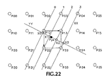
- FIG. 22 shows an example of the manner in which directional interpolation is performed.
- the present invention is implemented in a display system 30 as shown in FIG. 1A .
- This system includes image source 32 , I/O device 34 , input memory 36 , display processor 38 , output memory 40 and pixel display 42 .
- the image source 32 is a CPU or other device capable of generating image data directly, and of receiving image data from yet other sources such as I/O device 34 .
- the image source 32 operates to place image data 33 and image-processing commands 35 in input memory 36 , which is also accessible by the display processor 38 .
- the display processor produces a scaled output image 39 in output memory 40 , which is also accessible by the pixel display 42 .
- the pixel display retrieves the output image 39 present in the output memory 40 and displays it.
- the display processor 38 is shown in further detail in FIG. 1B and includes input memory interface 44 , control unit 46 , arithmetic-logic unit (ALU) 48 , memory 50 , output memory interface 52 and processing bus 54 .
- Control unit 46 which those skilled in the art will understand can be implemented in a variety of manners, including as miscellaneous logic or based on a microcontrol store read-only memory, supervises the functioning and interaction of the other units shown in FIG. 1B .
- the control unit 46 through input memory interface 44 accesses the input image data 33 ( FIG. 1A ) and processing commands 35 ( FIG. 1A ) present in input memory 36 ( FIG. 1A ).
- the control unit 46 also controls ALU 48 to perform the arithmetic and logic processing of data necessary to perform the image scaling procedure. Additionally, the control unit 46 stores and retrieves intermediate computational results to and from memory 50 . The control unit 46 through output memory interface 52 places the output image data 39 ( FIG. 1A ) in output memory 40 ( FIG. 1A ). Processing bus 54 provides a means to move data directly between the various data-handling units of FIG. 1B .
- the method of the invention is to produce as output a scaled version of an input pixel data source in which the processing performed is determined by the type of the relevant local input data, namely either graphics-generated data or video (natural image) data.
- the type of the relevant source data is determined by examination of the brightness levels of four pixels of the input data that are geometrically most closely associated with the target output pixel.
- Video-source data is assumed in the case the pixels exhibit four distinct brightness levels, while graphics-generated data is generally assumed otherwise.
- the invention uses a video-optimized scaling procedure in the case of video-source data, or selects one of five graphics-optimized scaling procedures to be applied in the case of graphics-source data.
- the invention utilizes a directional interpolation technique, wherein intermediate pixels that are produced in the process are aligned perpendicularly to the direction of minimum brightness level change.
- the technique additionally makes use of polyphase finite impulse response (FIR) filtering in the production of the output target pixel from the intermediate pixels.
- FIR polyphase finite impulse response
- the method of the invention applies to both black and white (gray scale) images, as well as to color images.
- it is the gray level of the pixel that is considered the brightness level.
- RGB or YUV representations are commonly employed, although other representations come within the scope of the invention.
- the individual color component intensity level red, blue or green
- the Y component value is used for the brightness level.
- comparisons are carried out to determine whether the brightness levels of two particular pixels are equal to each other, or to determine the number of distinct brightness levels exhibited by some number of pixels. Such comparisons may be carried out by first taking the difference of two brightness level values, and then determining whether the result is zero. Since brightness level values are subject to the influence of noise and other non-ideal factors, a range of result values that are close to zero but not necessarily exactly equal to zero, may optionally be accepted as being functionally equivalent to zero in the procedure just outlined.
- FIG. 2 shows a target output pixel Pyx.
- the four input pixels that are most closely associated with pixel Pyx coordinate-wise may be said to form a “center” region encompassing pixel Pyx, as shown in the figure.
- the brightness levels of the four center pixels are instrumental in determining the type of procedure to be applied in order to compute the brightness level of pixel Pyx.
- the existence of certain patterns of brightness levels in the four center pixels is sufficient in and of itself to specify the computational procedure to be employed.
- the patterns of brightness levels present in various of the input pixels surrounding the center region must additionally be taken into consideration to determine the computational procedure to be carried out.
- the brightness levels of certain of the input pixels in as large an area as a 4 ⁇ 6 sub-image portion of the input pixel data set may need to be examined in order to perform the method of the invention.
- Such a sub-image has the target output pixel Pyx and the center four input pixels at its center, as shown in FIG. 2 .
- the input pixel source data of which the sub-image shown in FIG. 2 is a portion, is a two-dimensional array of points, each having integer Y (vertical) and X (horizontal) coordinate values greater than or equal to zero.
- the pixel output data, of which target output pixel Pyx is one member, is also a two-dimensional array of points, which array may be considered as replicating the input image with a different resolution.
- the input pixels of the sub-image region are identified as shown in FIG. 2 by their coordinate locations relative to the pixel in the upper left corner of the region, pixel P 00 .
- the coordinates of the target output pixel Pyx are given by convention in terms of the pixel's coordinate location relative to the center region's upper left corner pixel, pixel P 12 , termed the “reference” pixel.
- the target pixel Pyx is shown in FIG. 2 as having non-integer coordinates, as would generally be the case.
- FIG. 2 illustrates the typical case where target pixel Pyx is located sufficiently far from any of the boundaries of the input pixel array that all pixels of sub-image region and the center area do in fact exist as part of the input data.
- pixel Pyx is located close to a boundary of the input pixel array, however, some of the pixels of FIG. 2 would not exist as part of the input data.
- any absent pixels are created (that is, appropriate brightness levels are assigned) in order that the center and sub-image areas be populated as required.
- the created pixels have their brightness level values set equal to zero.
- the brightness level of each created pixel is set equal to the brightness level of the nearest pixel(s) of the input image.
- the brightness level of pixel P 12 of the input data would be the value utilized for the brightness levels of created pixels P 00 , P 01 , P 02 , P 10 and P 11 ; the brightness level of pixel P 22 of the input data would be the value utilized for the brightness levels of created pixels P 20 and P 21 ; and so forth.
- FIGS. 3A-3E list an embodiment of the present invention. The determination of the center and sub-image pixels based on the location of the target output pixel Pyx ( 100 in FIG. 3A ) has already been discussed.
- instrumental to the invention is the determination of the number of brightness levels exhibited by the four input pixels P 12 , P 13 , P 22 and P 23 of the center region surrounding the target output pixel Pyx.
- determination is made of a number of distinct brightness levels. If the number of levels is four, video-source data is assumed and a Directional Interpolation algorithm is carried out, starting at block 160 . Otherwise, graphics-source data is assumed, and a determination is made as to which one of five graphics-optimized scaling procedures should be carried out.
- a Default Pixel Replication algorithm a Horizontal Pixel Replication algorithm
- a Vertical Pixel Replication algorithm a Vertical Pixel Replication algorithm
- a Diagonal Pixel Replication algorithm a Diagonal Pixel Replication algorithm
- an Anti-diagonal Pixel Replication algorithm The actions carried out in the case of each of these algorithms are discussed below.
- the Default Pixel Replication algorithm is employed ( 130 ) to compute the brightness level of the output target pixel Pyx.
- the level of pixel Pyx is set equal to the brightness level of the four center pixels, this being a special case of the more general algorithm.
- the case of two brightness levels being present among the four center pixels can occur in two ways.
- the first (Y branch from 300 ) covers the cases where two of the center pixels exhibit a first brightness level, and the two other center pixels exhibit a second brightness level (a “2:2 combination”).
- the second (N branch from 300 ) covers the cases where just one of the center pixels exhibits a first brightness level, and the three other center pixels exhibit a second brightness level (a “1:3 combination”).
- FIGS. 5A , 5 B and 5 C The cases of two brightness levels among the center pixels being in 2:2 combinations are illustrated in FIGS. 5A , 5 B and 5 C.
- the Horizontal Pixel Replication algorithm is employed ( 410 ); for the case of FIG. 5B (Y branch from 420 ), the Vertical Pixel Replication algorithm is employed ( 430 ).
- the Diagonal Pixel Replication algorithm or the Anti-diagonal Pixel Replication algorithm is employed, based upon the brightness levels of the other pixels in the 4-by-4 area immediately surrounding the center area of the sub-image ( 440 ).
- Nd the number of pixels whose brightness level matches that of the center diagonal pixels (P 12 and P 23 ), denoted by Nd, is less than the number of pixels whose brightness level matches that of the center anti-diagonal pixels (P 13 and P 22 ), denoted by Na (Y branch from 450 ), then the Diagonal Pixel Replication algorithm is employed ( 460 ); if Na is less than Nd (Y branch from 470 ), then the Anti-diagonal Pixel Replication algorithm is employed ( 480 ); else (Na equal to Nd: N branch from 470 ) the Default Pixel Replication algorithm is employed ( 490 ). (As discussed previously with regard to determination of equality of brightness levels, determination of the relative magnitudes of Nd and Na may be carried out in a similar manner so as to lessen the influence of noise and other non-ideal factors.)
- FIGS. 6 through 11 The cases of two brightness levels among the center pixels being in 1:3 combinations are illustrated in FIGS. 6 through 11 . Note that in each of these figures, the light pixels are all of a first brightness level; the dark pixels are all of a second brightness level; and the cross-hatched pixels are all of the same, unspecified brightness level (possibly either the first or the second brightness level).
- FIGS. 6 through 11 all illustrate the same basic configuration of pixel P 12 being that center pixel which has the first brightness level, while pixels P 13 , P 22 and P 23 all have the second brightness level. It is clear that the figures thus illustrate one-fourth of all possible 1:3 combination situations, and that all of the other situations can be derived by rotation of the figures through increments of 90 degrees; therefore it suffices to illustrate just those situations shown in the figures.
- the case of three brightness levels being present among the four center pixels implies that two of the pixels have a first brightness level, the third pixel has a second brightness level, and the fourth pixel has a third brightness level.
- the two same-level pixels can be aligned either horizontally, vertically, diagonally or anti-diagonally. Refer to FIGS. 12 through 21 , in which the light pixels are all of a first brightness level; the dark pixels are all of a second brightness level; and the cross-hatched pixels are all of a third brightness level (note that this differs from the illustration convention employed in FIGS. 6 through 11 ).
- FIGS. 12 and 13 illustrate two cases where the two same-level pixels of a three-value center are aligned horizontally. If x (the relative horizontal coordinate of output target pixel Pyx) is less than 0.5 (Y branch from 500 ), the Horizontal Pixel Replication algorithm is employed ( 510 ), else (N branch from 500 ; Y branch from 580 ) the Default Pixel Replication algorithm is instead utilized ( 590 ).
- FIGS. 14 and 15 illustrate two additional cases where the two same-level pixels of a three-value center are aligned horizontally. If x is greater than or equal to 0.5 (Y branch from 500 ), the Horizontal Pixel Replication algorithm is employed ( 510 ), else (Y branch from 500 ; Y branch from 580 ) the Default Pixel Replication algorithm is instead utilized ( 590 ).
- FIGS. 16 and 17 illustrate two cases where the two same-level pixels of a three-value center are aligned vertically. If y (the relative vertical coordinate of output target pixel Pyx) is less than 0.5 (Y branch from 520 ), the Vertical Pixel Replication algorithm is employed ( 530 ), else (N branch from 520 ; Y branch from 580 ) the Default Pixel Replication algorithm is instead utilized ( 590 ).
- FIGS. 18 and 19 illustrate two additional cases where the two same-level pixels of a three-value center are aligned vertically. If y is greater than or equal to 0.5 (Y branch from 520 ), the Vertical Pixel Replication algorithm is employed ( 530 ), else (N branch from 520 ; Y branch from 580 ) the Default Pixel Replication algorithm is instead utilized ( 590 ).
- FIG. 20 illustrates a case where the two same-level pixels of a three-value center are aligned diagonally. For this case, a determination is made whether to employ an appropriate graphics scaling procedure or to employ directional interpolation to produce the target output pixel, as now described.
- FIG. 21 illustrates a case where the two same-level pixels of a three-value center are aligned anti-diagonally. For this case, a determination is made whether to employ an appropriate graphics scaling procedure or to employ directional interpolation to produce the target output pixel, as now described.
- the Directional Interpolation algorithm is employed ( 160 ) to produce the target output pixel.
- the Directional Interpolation algorithm consists of seven actions (blocks 160 , 170 , 180 , 190 , 200 , 210 and 220 of FIGS. 3A-3B ).
- a weighted sum of the absolute values of the differences of the brightness levels of various pairs of pixels in the sub-image is computed to determine the brightness gradient for each of several directions.
- brightness gradients are computed for four directions: 0 degrees, 45 degrees, 90 degrees and 135 degrees relative to the horizontal (X) axis.
- brightness gradients are computed for four additional directions: 26.6 degrees, 63.4 degrees, 116.6 degrees and 153.4 degrees.
- FIG. 22 illustrates the case of the brightness gradient in the 63.4 degree direction having been determined as having the minimum relative value. This direction is identified in the figure as “XX” (not to be confused with, and generally not identical to, the horizontal X axis).
- line segments are determined, oriented in the XX direction and passing through the four center pixels as well as other pixels of the sub-image, depending upon which direction has the minimum gradient.
- these line segments are identified as “ 0 ”, “ 1 ”, “ 2 ” and “ 3 ”.
- the direction perpendicular to XX is identified; in FIG. 22 this is identified as “YY” (not to be confused with, and generally not identical to, the horizontal Y axis).
- a line segment is determined, oriented in the YY direction and passing through pixel Pyx.
- the brightness level of each of the intermediate pixels is computed using linear interpolation, based on the brightness levels of the two nearest pixels of the sub-image through which the associated XX-directed line segment passes.
- the brightness level of X 0 is determined using linear interpolation based on the brightness levels of P 12 and P 31 ;
- X 1 is likewise determined from P 03 and P 22 ;
- X 2 is likewise determined from P 13 and P 32 ;
- X 3 is likewise determined from P 04 and P 23 .
- a person of reasonable skill in the art should recognize that other filtering techniques might be employed in alternative embodiments of the invention.
- the brightness level of the target output pixel Pyx is determined from the brightness levels of the four intermediate pixels through use of polyphase FIR filtering.
- polyphase FIR filtering A person of reasonable skill in the art should recognize that other filtering techniques might be employed in alternative embodiments of the invention.
- the weights w i and u i are a function of the position of Pyx, the target output pixel.
- the weights v i and t i are a function of the position of Pyx, the target output pixel.
- a FIR polyphase filter having the number of phases (denoted by N) equal to 64 is used in a preferred embodiment.
- the phase of the variable of interest must be determined.
- the phase of y is therefore an integer in the range from 0 to (N ⁇ 1).
- Filtering the brightness levels of four intermediate pixels to produce the brightness level for target output pixel Pyx implies the use of four sets of coefficients for the polyphase filter, the values of each set being a function of the phase of the variable of interest.
- Table 1 lists the coefficients used in a preferred embodiment of the polyphase filter.
- Phase Coef1 Coef2 Coef3 Coef4 0 0 128 0 0 1 ⁇ 1 128 1 0 2 ⁇ 2 128 2 0 3 ⁇ 3 127 4 0 4 ⁇ 3 127 5 ⁇ 1 5 ⁇ 4 126 6 0 6 ⁇ 4 125 7 0 7 ⁇ 5 125 9 ⁇ 1 8 ⁇ 5 123 10 0 9 ⁇ 6 122 12 0 10 ⁇ 6 121 13 0 11 ⁇ 6 119 16 ⁇ 1 12 ⁇ 7 118 18 ⁇ 1 13 ⁇ 7 116 20 ⁇ 1 14 ⁇ 7 114 22 ⁇ 1 15 ⁇ 7 112 24 ⁇ 1 16 ⁇ 7 110 26 ⁇ 1 17 ⁇ 7 108 28 ⁇ 1 18 ⁇ 7 106 31 ⁇ 2 19 ⁇ 7 104 33 ⁇ 2 30 ⁇ 7 101 36 ⁇ 2 21 ⁇ 7 99 38 ⁇ 2 22 ⁇ 7 96 41 ⁇ 2 23 ⁇ 6 94 43 ⁇ 3 24
- coef0, coef1, coef2, and coef3 are the coefficients used in the implementation of the polyphase filter and are functions of the phase of the identified variable of interest (refer to Table 1). Additionally note that the mathematical function fract is referred to, which represents taking the fraction portion of the argument.
- inHeight and outHeight represent the vertical extent of the input and output images respectively; inWidth and outWidth represent the horizontal extent of the input and output images respectively.
- h Lambda (inWidth/outWidth);
- v Lambda (inHeight/outHeight);
Abstract
Description
S h =w 0 |P 11 −P 12 |+w 1 |P 12 −P 13 |+w 2 |P 13 −P 14 |
+w3|P21−P22|+w4|P22−P23|+w5|P23−P24|
S v =w 0 |P 02 −P 12 |+w 1 |P 12 −P 22 |+w 2 |P 22 −P 32 |
+w3|P03−P13|+w4|P13−P23|+w5|P23−P33|
S d =u 0 |P 01 −P 12 |+u 1 |P 12 −P 23 |+u 2 |P 23 −P 34 |
+u3|P11−P22|+u4|P22−P33|
+u5|P02−P13|+u6|P13−P24|
S a =u 0 |P 04 −P 13 |+u 1 |P 13 −P 22 |+u 2 |P 22 −P 31|
+u3|P03−P12|+u4|P12−P21|
+u5|P14−P23|+u6|P23−P32|
S 1d =t 0 |P 02 −P 14 |+t 1 |P 01 −P 13 |+t 2 |P 13 −P 25 |+t 3 |P 12 −P 24|
+t4|P11−P23|+t5|P10−P22|+t6|P22−P34|+t7|P21−P33|
S 1a =t 0 |P 03 −P 11 |+t 1 |P 04 −P 12 |+t 2 |P 12 −P 20 |+t 3 |P 13 −P 21|
+t4|P14−P22|+t5|P15−P23|+t6|P23−P31|+t7|P24−P33|
S 2d =v 0 |P 00 −P 21 |+v 1 |P 11 −P 32 |+v 2 |P 01 −P 22 |+v 3 |P 12 −P 33|
+t4|P02−P23|+t5|P13−P34|+t6|P04−P25|+t7|P14−P35|
S 2a =v 0 |P 05 −P 24 |+v 1 |P 14 −P 33 |+v 2 |P 04 −P 23 |+v 3 |P 13 −P 32|
+t4|P03−P22|+t5|P12−P31|+t6|P02−P21|+t7|P11−P30|
phase(y)=int(N*y)
where the variable of interest (y) is constrained to have a value greater than or equal to 0, and less than 1. The phase of y is therefore an integer in the range from 0 to (N−1).
| TABLE 1 |
| Polyphase filter coefficients |
| Phase | Coef1 | Coef2 | Coef3 | Coef4 |
| 0 | 0 | 128 | 0 | 0 |
| 1 | −1 | 128 | 1 | 0 |
| 2 | −2 | 128 | 2 | 0 |
| 3 | −3 | 127 | 4 | 0 |
| 4 | −3 | 127 | 5 | −1 |
| 5 | −4 | 126 | 6 | 0 |
| 6 | −4 | 125 | 7 | 0 |
| 7 | −5 | 125 | 9 | −1 |
| 8 | −5 | 123 | 10 | 0 |
| 9 | −6 | 122 | 12 | 0 |
| 10 | −6 | 121 | 13 | 0 |
| 11 | −6 | 119 | 16 | −1 |
| 12 | −7 | 118 | 18 | −1 |
| 13 | −7 | 116 | 20 | −1 |
| 14 | −7 | 114 | 22 | −1 |
| 15 | −7 | 112 | 24 | −1 |
| 16 | −7 | 110 | 26 | −1 |
| 17 | −7 | 108 | 28 | −1 |
| 18 | −7 | 106 | 31 | −2 |
| 19 | −7 | 104 | 33 | −2 |
| 30 | −7 | 101 | 36 | −2 |
| 21 | −7 | 99 | 38 | −2 |
| 22 | −7 | 96 | 41 | −2 |
| 23 | −6 | 94 | 43 | −3 |
| 24 | −6 | 91 | 46 | −3 |
| 25 | −6 | 88 | 49 | −3 |
| 26 | −6 | 86 | 51 | −3 |
| 27 | −6 | 83 | 54 | −3 |
| 28 | −5 | 80 | 57 | −4 |
| 29 | −5 | 77 | 60 | −4 |
| 30 | −5 | 74 | 63 | −4 |
| 31 | −5 | 71 | 66 | −4 |
| 32 | −5 | 69 | 69 | −5 |
| 33 | −4 | 66 | 71 | −5 |
| 34 | −4 | 63 | 74 | −5 |
| 35 | −4 | 60 | 77 | −5 |
| 36 | −4 | 57 | 80 | −5 |
| 37 | −3 | 54 | 83 | −6 |
| 38 | −3 | 51 | 86 | −6 |
| 39 | −3 | 49 | 88 | −6 |
| 40 | −3 | 46 | 91 | −6 |
| 41 | −3 | 43 | 94 | −6 |
| 42 | −2 | 41 | 96 | −7 |
| 43 | −2 | 38 | 99 | −7 |
| 44 | −2 | 36 | 101 | −7 |
| 45 | −2 | 33 | 104 | −7 |
| 46 | −2 | 31 | 106 | −7 |
| 47 | −1 | 28 | 108 | −7 |
| 48 | −1 | 26 | 110 | −7 |
| 49 | −1 | 24 | 112 | −7 |
| 50 | −1 | 22 | 114 | −7 |
| 51 | −1 | 20 | 116 | −7 |
| 52 | −1 | 18 | 118 | −7 |
| 53 | −1 | 16 | 119 | −6 |
| 54 | 0 | 13 | 121 | −6 |
| 55 | 0 | 12 | 122 | −6 |
| 56 | 0 | 10 | 123 | −5 |
| 57 | −1 | 9 | 125 | −5 |
| 58 | 0 | 7 | 125 | −4 |
| 59 | 0 | 6 | 126 | −4 |
| 60 | −1 | 5 | 127 | −3 |
| 61 | 0 | 4 | 127 | −3 |
| 62 | 0 | 2 | 128 | −2 |
| 63 | 0 | 1 | 128 | −1 |
x0=(P02+(x*(P03−P02)));
x1=(P12+(x*(P13−P12)));
x2=(P22+(x*(P23−P22)));
x3=(P32+(x*(P33−P32)));
Pyx=((coef0(phase(y))*x0)+(coef1(phase(y))*x1)
+(coef2(phase(y))*x2)+(coef3(phase(y))*x3))
x0=(P11+(y*(P21−P11)));
x1=(P12+(y*(P22−P12)));
x2=(P13+(y*(P23−P13)));
x3=(P14+(y*(P24−P14)));
Pyx=((coef0(phase(x))*x0)+(coef1(phase(x))*x1)
+(coef2(phase(x))*x2)+(coef3(phase(x))*x3))
x1=(P12+((x+y)*((P23−P12)/2)));
-
- if x≧y,
x3=(P03+((x+y)*(P14−P03)/2)); - if (x+y)<1,
x0=(P22+((1−x−y)*(P11−P22)/2));
x2=(P31+((1−x−y)*(P20−P31)/2));
else
x0=(P22+((x+y−1)*(P33−P22)/2));
x2=(P31+((x+y−1)*(P42−P31)/2));
Pyx=((coef0(phase(x−y))*x0)+(coef1(phase(x−y))*x1)
+(coef2(phase(x−y))*x2)+(coef3(phase(x−y))*x3));
else
x3=(P21+((x+y)*(P32−P21)/2)); - if (x+y)<1
x0=(P13+((1−x−y)*(P02−P13)/2));
x2=(P22+((1−x−y)*(P11−P22)/2));
else
x0=(P13+((x+y−1)*(P24−P13)/2));
x2=(P22+((x+y−1)*(P33−P22)/2));
Pyx=((coef0(phase(y−x))*x0)+(coef1(phase(y−x))*x1)
+(coef2(phase(y−x))*x2)+(coef3(phase(y−x))*x3))
- if x≧y,
-
- if (x+y)<1,
x0=(P02+((1−x+y)*(P11−P02)/2));
x2=(P13+((1−x+y)*(P22−P13)/2)); - if (x>y),
x1=(P12+((x−y)*(P03−P12)/2));
x3=(P03+((x−y)*(P14−P03)/2));
else
x1=(P12+((y−x)*(P21−P12)/2));
x3=(P03+((y−x)*(P14−P03)/2));
Pyx=((coef0(phase(x+y))*x0)+(coef1(phase(x+y))*x1)
+(coef2(phase(x+y))*x2)+(coef3(phase(x+y))*x3));
else
x1=(P13+((1−x+y)*(P22−P13)/2));
x3=(P24+((1−x+y)*(P33−P24)/2)); - if (x>y),
x0=(P12+((x−y)*(P03−P12)/2));
x2=(P03+((x−y)*(P14−P03)/2));
else
x0=(P12+((y−x)*(P21−P12)/2));
x2=(P03+((y−x)*(P14−P03)/2));
Pyx=((coef0(phase(x+y−1))*x0)+(coef1(phase(x+y−1))*x1)
+(coef2(phase(x+y−1))*x2)+(coef3(phase(x+y−1))*x3))
- if (x+y)<1,
a=fract(1−x+(2*y));
x1=(P12+((y+(2*x))*(P24−P12)/5));
x2=(P23+(((3−y)−(2*x))*(P11−P23)/5));
-
- if ((2*y)−x)<1,
- if ((2*x)+y)<2,
x0=(P13+((2−(2*x)−y)*(P01−P13)/5));
else
x0=(P13+((2−(2*x)−y)*(P25−P13)/5)); - if x>(2*y),
x3=(P14+((4−(2*x)−y)*(P02−P14)/5));
Pyx=((coef0(phase(a))*x3)+(coef1(phase(a))*x0)
+(coef2(phase(a))*x1)+(coef3(phase(a))*x2)); - else
- if ((2*x)+y)≧1,
x3=(P22+(((2*x)+y−1)*(P34−P22)/5));
else
x3=(P22+((1−(2*x)−y)*(P10−P22)/5));
Pyx=((coef0(phase(a))*x0)+(coef1(phase(a))*x1)
+(coef2(phase(a))*x2)+(coef3(phase(a))*x3));
else
x0=(P21+((1+(2*x)+y)*(P33−P21)/5));
- if ((2*x)+y)≧1,
- if (y+(2*x))>1
x3=(P22+((y+(2*x)−1)*(P34−P22)/5));
else
x3=(P22+((1−(2*x)−y)*(P10−P22)/5));
Pyx=((coef0(phase(a))*x1)+(coef1(phase(a))*x2)
+(coef2(phase(a))*x3)+(coef3(phase(a))*x0))
a=fract(x+(2*y));
x1=(P13+((2+y−(2*x))*(P21−P13)/5));
x2=(P22+((1−y+(2*x))*(P14−P22)/5));
-
- if ((2*y)+x)<2,
- if y<(2*x),
x0=(P12+(((2*x)−y)*(P04−P12)/5));
else
x0=(P12+(((2*x)−y)*(P20−P12)/5)); - if (x+(2*y))<1,
x3=(P11+((2+(2*x)−y)*(P03−P11)/5));
Pyx=((coef0(phase(a))*x3)+(coef1(phase(a))*x0)
+(coef2(phase(a))*x1)+(coef3(phase(a))*x2)); - else
- if (y+1)<(2*x),
x3=(P23+(((2*x)−y)*(P31−P23)/5));
else
x3=(P23+(((2*x)−y)*(P15−P23)/5));
Pyx=((coef0(phase(a))*x0)+(coef1(phase(a))*x1)
+(coef2(phase(a))*x2)+(coef3(phase(a))*x3))
else
x0=(P24+((3−(2*x)+y)*(P32−P24)/5));
- if (y+1)<(2*x),
- if (y+1)<(2*x),
x3=(P23+(((2*x)−y)*(P31−P23)/5));
else
x3=(P23+(((2*x)−y)*(P15−P23)/5));
Pyx=((coef0(phase(a))*x1)+(coef1(phase(a))*x2)
+(coef2(phase(a))*x3)+(coef3(phase(a))*x0))
a=fract((1−y)+(2*x));
x1=(P12+((x+(2*y))*(P33−P12)/5));
x2=(P23+((3−x−(2*y))*(P02−P23)/5));
-
- if ((2*x)−y)<1,
x0=(P22+((2−(2*y)−x)*(P01−P22)/5)); - if y>(2*x),
x3=(P11+(((4−x−(2*y))*(P32−P11)/5));
Pyx=((coef0(phase(a))*x3)+(coef1(phase(a))*x0)
+(coef2(phase(a))*x1)+(coef3(phase(a))*x2));
else
x3=(P13+(((2*y)+x−1)*(P34−P13)/5));
Pyx=((coef0(phase(a))*x0)+(coef1(phase(a))*x1)
+(coef2(phase(a))*x2)+(coef3(phase(a))*x3));
else
x0=(P03+((1+(2*x)+y)*(P24−P03)/5));
x3=(P13+((y+(2*x)−1)*(P34−P13)/5));
Pyx=((coef0(phase(a))*x1)+(coef1(phase(a))*x2)
+(coef2(phase(a))*x3)+(coef3(phase(a))*x0))
- if ((2*x)−y)<1,
a=fract(y+(2*x));
x1=(P22+((2+x−(2*y))*(P03−P22)/5);
x2=(P13+((1−x+(2*y))*(P32−P13)/5));
-
- if (y+(2*x))<2,
x0=(P12+(((2*y)−x)*(P31−P12)/5)); - if ((2*x)+y)<1,
x3=(P02+((2+(2*y)−x)*(P21−P02)/5));
Pyx=((coef0(phase(a))*x3)+(coef1(phase(a))*x0)
+(coef2(phase(a))*x1)+(coef3(phase(a))*x2));
else
x3=(P23+((1−(2*y)+x)*(P04−P23)/5));
Pyx=((coef0(phase(a))*x0)+(coef1(phase(a))*x1)
+(coef2(phase(a))*x2)+(coef3(phase(a))*x3));
else
x0=(P33+(3+x−(2*y))*(P14−P33)/5));
x3=(P23+((1+x−(2*y))*(P04−P23)/5));
Pyx=((coef0(phase(a))*x1)+(coef1(phase(a))*x2)
+(coef2(phase(a))*x3)+(coef3(phase(a))*x0))
- if (y+(2*x))<2,
hLambda=(inWidth/outWidth);
vLambda=(inHeight/outHeight);
Pyx=P12+((P22−P12)*((y−((1−vLambda)/2))/vLambda));
Pyx=P13+((P23−P13)*((y−((1−vLambda)/2))/vLambda));
Else
Px1=P12+((P13−P12)*((x−((1−hLambda)/2))/hLambda));
Px2=P22+((P23−P22)*((x−((1−hLambda)/2))/hLambda));
Pyx=Px1+((Px2−Px1)*((y−((1−vLambda)/2))/vLambda))
Pyx=P12+((P22−P12)*((y−((1−vLambda)/2))/vLambda));
-
- If y<0.5, Pyx=P12;
- Else Pyx=P22;
-
- If y<0.5, Pyx=P13;
- Else Pyx=P23;
Pyx=P12+((P13−P12)*((x−((1−hLambda)/2))/hLambda));
Pyx=P13+((P12−P13)*((1−x+y−((1−Lambda)/2))/Lambda));
Else
Pyx=P13+((P23−P13)*((1−x+y−((1−Lambda)/2))/Lambda));
Pyx=P12+((P22−P12)*((1−x+y−((3−Lambda)/2))/Lambda));
Else
Pyx=P23+((P22−P23)*((1−x+y−((3−Lambda)/2))/Lambda));
Pyx=P12+((P13−P12)*((x+y−((1−Lambda)/2))/Lambda));
Else
Pyx=P12+((P22−P12)*((x+y−((1−Lambda)/2))/Lambda));
Pyx=P22+((P23−P22)*((x+y−((3−Lambda)/2))/Lambda));
Claims (20)
Priority Applications (1)
| Application Number | Priority Date | Filing Date | Title |
|---|---|---|---|
| US11/616,763 US7324709B1 (en) | 2001-07-13 | 2006-12-27 | Method and apparatus for two-dimensional image scaling |
Applications Claiming Priority (3)
| Application Number | Priority Date | Filing Date | Title |
|---|---|---|---|
| US30539301P | 2001-07-13 | 2001-07-13 | |
| US10/154,543 US7171059B1 (en) | 2002-05-23 | 2002-05-23 | Method and apparatus for two-dimensional image scaling |
| US11/616,763 US7324709B1 (en) | 2001-07-13 | 2006-12-27 | Method and apparatus for two-dimensional image scaling |
Related Parent Applications (1)
| Application Number | Title | Priority Date | Filing Date |
|---|---|---|---|
| US10/154,543 Continuation US7171059B1 (en) | 2001-07-13 | 2002-05-23 | Method and apparatus for two-dimensional image scaling |
Publications (1)
| Publication Number | Publication Date |
|---|---|
| US7324709B1 true US7324709B1 (en) | 2008-01-29 |
Family
ID=38973985
Family Applications (1)
| Application Number | Title | Priority Date | Filing Date |
|---|---|---|---|
| US11/616,763 Expired - Fee Related US7324709B1 (en) | 2001-07-13 | 2006-12-27 | Method and apparatus for two-dimensional image scaling |
Country Status (1)
| Country | Link |
|---|---|
| US (1) | US7324709B1 (en) |
Cited By (5)
| Publication number | Priority date | Publication date | Assignee | Title |
|---|---|---|---|---|
| US20100123824A1 (en) * | 2008-10-10 | 2010-05-20 | Noriaki Wada | Signal processing apparatus, signal processing method, and program for signal processing |
| US20100283799A1 (en) * | 2009-05-05 | 2010-11-11 | Analog Devices, Inc. | Content adaptive scaler based on a farrow structure |
| US20160119578A1 (en) * | 2014-10-27 | 2016-04-28 | Samsung Display Co., Ltd. | Image processing device and image processing method |
| US20190205019A1 (en) * | 2017-12-28 | 2019-07-04 | Samsung Electronics Co., Ltd. | Image magnifying apparatus |
| US11640649B2 (en) * | 2019-06-19 | 2023-05-02 | Samsung Electronics Co., Ltd. | Methods and apparatus for efficient range calculation |
Citations (36)
| Publication number | Priority date | Publication date | Assignee | Title |
|---|---|---|---|---|
| US4680720A (en) * | 1983-10-17 | 1987-07-14 | Kabushiki Kaisha Toshiba | Dot interpolation control system |
| US5019903A (en) * | 1989-05-04 | 1991-05-28 | Sony Corporation | Spatial interpolation between lines of a supersampled digital video signal in accordance with a gradient vector selected for maximum matching of blocks of samples which are offset in opposite directions |
| US5054100A (en) * | 1989-11-16 | 1991-10-01 | Eastman Kodak Company | Pixel interpolator with edge sharpening |
| US5257326A (en) * | 1990-04-20 | 1993-10-26 | Hitachi, Ltd. | Method and apparatus for interpolating a video signal of a picture element which has not been sampled and transmitted by an interleave sampling operation |
| US5296941A (en) * | 1991-12-20 | 1994-03-22 | Matsushita Electric Industrial Co, Ltd. | Gradation compensation apparatus of video image |
| US5347599A (en) * | 1991-06-14 | 1994-09-13 | Matsushita Electric Industrial Co., Ltd. | Adaptive interpolation method and apparatus using correlation detection |
| US5511137A (en) * | 1988-04-07 | 1996-04-23 | Fujitsu Limited | Process and apparatus for image magnification |
| US5513281A (en) * | 1991-12-02 | 1996-04-30 | Matsushita Electric Industrial Co., Ltd. | Interpolation method and apparatus by correlation detection using fuzzy inference |
| US5526020A (en) * | 1991-10-07 | 1996-06-11 | Xerox Corporation | Image editing system and method having improved automatic object selection |
| US5579053A (en) | 1994-03-03 | 1996-11-26 | Siemens Aktiengesellschaft | Method for raster conversion by interpolating in the direction of minimum change in brightness value between a pair of points in different raster lines fixed by a perpendicular interpolation line |
| US5703968A (en) * | 1994-04-19 | 1997-12-30 | Matsushita Electric Industrial Co., Ltd. | Method and apparatus for detecting interpolation line |
| US5832143A (en) * | 1996-01-17 | 1998-11-03 | Sharp Kabushiki Kaisha | Image data interpolating apparatus |
| US5852470A (en) * | 1995-05-31 | 1998-12-22 | Sony Corporation | Signal converting apparatus and signal converting method |
| US5875268A (en) * | 1993-09-27 | 1999-02-23 | Canon Kabushiki Kaisha | Image processing with low-resolution to high-resolution conversion |
| US5917963A (en) * | 1995-09-21 | 1999-06-29 | Canon Kabushiki Kaisha | Image processing apparatus and image processing method |
| US5946044A (en) * | 1995-06-30 | 1999-08-31 | Sony Corporation | Image signal converting method and image signal converting apparatus |
| US5966183A (en) * | 1995-03-22 | 1999-10-12 | Sony Corporation | Signal converter and signal conversion method |
| US5991463A (en) * | 1995-11-08 | 1999-11-23 | Genesis Microchip Inc. | Source data interpolation method and apparatus |
| US5991464A (en) * | 1998-04-03 | 1999-11-23 | Odyssey Technologies | Method and system for adaptive video image resolution enhancement |
| US6005989A (en) * | 1995-12-28 | 1999-12-21 | Sagem Sa | Method for modifying the resolution of a digitized image |
| US6009213A (en) * | 1996-04-25 | 1999-12-28 | Canon Kabushiki Kaisha | Image processing apparatus and method |
| US6016164A (en) * | 1994-11-28 | 2000-01-18 | Sony Corporation | Image signal interpolating apparatus |
| US6157749A (en) * | 1997-03-05 | 2000-12-05 | Canon Kabushiki Kaisha | Image processing apparatus and method, and storing medium |
| US6266454B1 (en) * | 1996-07-17 | 2001-07-24 | Sony Corporation | Device and method for processing, image and device and method for encoding image |
| US20010035969A1 (en) * | 1996-11-22 | 2001-11-01 | Sony Corporation | Video processing apparatus for processing pixel for generating high-picture-quality image, method thereof, and video printer to which they are applied |
| US6324309B1 (en) * | 1997-06-27 | 2001-11-27 | Sharp Kabushiki Kaisha | Image processing apparatus |
| US20020047907A1 (en) * | 2000-08-30 | 2002-04-25 | Nikon Corporation | Image processing apparatus and storage medium for storing image processing program |
| US6408109B1 (en) * | 1996-10-07 | 2002-06-18 | Cognex Corporation | Apparatus and method for detecting and sub-pixel location of edges in a digital image |
| US20020076121A1 (en) * | 2000-06-13 | 2002-06-20 | International Business Machines Corporation | Image transform method for obtaining expanded image data, image processing apparatus and image display device therefor |
| US6463178B1 (en) * | 1997-06-16 | 2002-10-08 | Sony Corporation | Image processing device and method, and transmission medium, transmission method and image format |
| US20030007702A1 (en) * | 1996-03-28 | 2003-01-09 | Fuji Photo Film Co., Ltd. | Interpolating operation method and apparatus for image signals |
| US20030112369A1 (en) * | 2001-12-14 | 2003-06-19 | Dae-Woon Yoo | Apparatus and method for deinterlace of video signal |
| US6591398B1 (en) * | 1999-02-12 | 2003-07-08 | Sony Corporation | Multiple processing system |
| US6912014B2 (en) * | 2000-02-10 | 2005-06-28 | Sony Corporation | Image processing device and method, and recording medium |
| US20050226526A1 (en) * | 2003-01-09 | 2005-10-13 | Sony Corporation | Image processing device and method |
| US7171059B1 (en) * | 2002-05-23 | 2007-01-30 | Pixelworks, Inc. | Method and apparatus for two-dimensional image scaling |
-
2006
- 2006-12-27 US US11/616,763 patent/US7324709B1/en not_active Expired - Fee Related
Patent Citations (38)
| Publication number | Priority date | Publication date | Assignee | Title |
|---|---|---|---|---|
| US4680720A (en) * | 1983-10-17 | 1987-07-14 | Kabushiki Kaisha Toshiba | Dot interpolation control system |
| US5511137A (en) * | 1988-04-07 | 1996-04-23 | Fujitsu Limited | Process and apparatus for image magnification |
| US5019903A (en) * | 1989-05-04 | 1991-05-28 | Sony Corporation | Spatial interpolation between lines of a supersampled digital video signal in accordance with a gradient vector selected for maximum matching of blocks of samples which are offset in opposite directions |
| US5054100A (en) * | 1989-11-16 | 1991-10-01 | Eastman Kodak Company | Pixel interpolator with edge sharpening |
| US5257326A (en) * | 1990-04-20 | 1993-10-26 | Hitachi, Ltd. | Method and apparatus for interpolating a video signal of a picture element which has not been sampled and transmitted by an interleave sampling operation |
| US5347599A (en) * | 1991-06-14 | 1994-09-13 | Matsushita Electric Industrial Co., Ltd. | Adaptive interpolation method and apparatus using correlation detection |
| US5526020A (en) * | 1991-10-07 | 1996-06-11 | Xerox Corporation | Image editing system and method having improved automatic object selection |
| US5513281A (en) * | 1991-12-02 | 1996-04-30 | Matsushita Electric Industrial Co., Ltd. | Interpolation method and apparatus by correlation detection using fuzzy inference |
| US5296941A (en) * | 1991-12-20 | 1994-03-22 | Matsushita Electric Industrial Co, Ltd. | Gradation compensation apparatus of video image |
| US5875268A (en) * | 1993-09-27 | 1999-02-23 | Canon Kabushiki Kaisha | Image processing with low-resolution to high-resolution conversion |
| US5579053A (en) | 1994-03-03 | 1996-11-26 | Siemens Aktiengesellschaft | Method for raster conversion by interpolating in the direction of minimum change in brightness value between a pair of points in different raster lines fixed by a perpendicular interpolation line |
| US5703968A (en) * | 1994-04-19 | 1997-12-30 | Matsushita Electric Industrial Co., Ltd. | Method and apparatus for detecting interpolation line |
| US6016164A (en) * | 1994-11-28 | 2000-01-18 | Sony Corporation | Image signal interpolating apparatus |
| US5966183A (en) * | 1995-03-22 | 1999-10-12 | Sony Corporation | Signal converter and signal conversion method |
| US5852470A (en) * | 1995-05-31 | 1998-12-22 | Sony Corporation | Signal converting apparatus and signal converting method |
| US5946044A (en) * | 1995-06-30 | 1999-08-31 | Sony Corporation | Image signal converting method and image signal converting apparatus |
| US5917963A (en) * | 1995-09-21 | 1999-06-29 | Canon Kabushiki Kaisha | Image processing apparatus and image processing method |
| US6219464B1 (en) * | 1995-11-08 | 2001-04-17 | Genesis Microchip Inc. | Source data interpolation method and apparatus |
| US5991463A (en) * | 1995-11-08 | 1999-11-23 | Genesis Microchip Inc. | Source data interpolation method and apparatus |
| US6005989A (en) * | 1995-12-28 | 1999-12-21 | Sagem Sa | Method for modifying the resolution of a digitized image |
| US5832143A (en) * | 1996-01-17 | 1998-11-03 | Sharp Kabushiki Kaisha | Image data interpolating apparatus |
| US20030007702A1 (en) * | 1996-03-28 | 2003-01-09 | Fuji Photo Film Co., Ltd. | Interpolating operation method and apparatus for image signals |
| US6009213A (en) * | 1996-04-25 | 1999-12-28 | Canon Kabushiki Kaisha | Image processing apparatus and method |
| US6266454B1 (en) * | 1996-07-17 | 2001-07-24 | Sony Corporation | Device and method for processing, image and device and method for encoding image |
| US6408109B1 (en) * | 1996-10-07 | 2002-06-18 | Cognex Corporation | Apparatus and method for detecting and sub-pixel location of edges in a digital image |
| US6690842B1 (en) * | 1996-10-07 | 2004-02-10 | Cognex Corporation | Apparatus and method for detection and sub-pixel location of edges in a digital image |
| US20010035969A1 (en) * | 1996-11-22 | 2001-11-01 | Sony Corporation | Video processing apparatus for processing pixel for generating high-picture-quality image, method thereof, and video printer to which they are applied |
| US6157749A (en) * | 1997-03-05 | 2000-12-05 | Canon Kabushiki Kaisha | Image processing apparatus and method, and storing medium |
| US6463178B1 (en) * | 1997-06-16 | 2002-10-08 | Sony Corporation | Image processing device and method, and transmission medium, transmission method and image format |
| US6324309B1 (en) * | 1997-06-27 | 2001-11-27 | Sharp Kabushiki Kaisha | Image processing apparatus |
| US5991464A (en) * | 1998-04-03 | 1999-11-23 | Odyssey Technologies | Method and system for adaptive video image resolution enhancement |
| US6591398B1 (en) * | 1999-02-12 | 2003-07-08 | Sony Corporation | Multiple processing system |
| US6912014B2 (en) * | 2000-02-10 | 2005-06-28 | Sony Corporation | Image processing device and method, and recording medium |
| US20020076121A1 (en) * | 2000-06-13 | 2002-06-20 | International Business Machines Corporation | Image transform method for obtaining expanded image data, image processing apparatus and image display device therefor |
| US20020047907A1 (en) * | 2000-08-30 | 2002-04-25 | Nikon Corporation | Image processing apparatus and storage medium for storing image processing program |
| US20030112369A1 (en) * | 2001-12-14 | 2003-06-19 | Dae-Woon Yoo | Apparatus and method for deinterlace of video signal |
| US7171059B1 (en) * | 2002-05-23 | 2007-01-30 | Pixelworks, Inc. | Method and apparatus for two-dimensional image scaling |
| US20050226526A1 (en) * | 2003-01-09 | 2005-10-13 | Sony Corporation | Image processing device and method |
Non-Patent Citations (2)
| Title |
|---|
| Gonzalez, R., Woods, R., Digital Image Processing, 1992, Addison-Wesley, ISBN 0-201-50803-6, p. 198-199. |
| Kowk, W., Sun, H., Multi-directional interpolation for spatial error concealment, Aug. 1993, Consumer Electronics, IEEE Transactions on , ISSN: 0098-3063, INSPEC Accession No. 4561878. |
Cited By (12)
| Publication number | Priority date | Publication date | Assignee | Title |
|---|---|---|---|---|
| US20100123824A1 (en) * | 2008-10-10 | 2010-05-20 | Noriaki Wada | Signal processing apparatus, signal processing method, and program for signal processing |
| US8310592B2 (en) * | 2008-10-10 | 2012-11-13 | Panasonic Corporation | Signal processing apparatus, signal processing method, and program for signal processing |
| US20100283799A1 (en) * | 2009-05-05 | 2010-11-11 | Analog Devices, Inc. | Content adaptive scaler based on a farrow structure |
| WO2010129548A1 (en) * | 2009-05-05 | 2010-11-11 | Analog Devices, Inc. | Content adaptive scaler based on a farrow structure |
| CN102460561A (en) * | 2009-05-05 | 2012-05-16 | 美国亚德诺半导体公司 | Content adaptive scaler based on farrow structure |
| US8346021B2 (en) | 2009-05-05 | 2013-01-01 | Analog Devices, Inc. | Content adaptive scaler based on a farrow structure |
| CN102460561B (en) * | 2009-05-05 | 2015-01-07 | 美国亚德诺半导体公司 | Content adaptive scaler based on farrow structure |
| US20160119578A1 (en) * | 2014-10-27 | 2016-04-28 | Samsung Display Co., Ltd. | Image processing device and image processing method |
| US9674484B2 (en) * | 2014-10-27 | 2017-06-06 | Samsung Display Co., Ltd. | Image processing device and image processing method |
| US20190205019A1 (en) * | 2017-12-28 | 2019-07-04 | Samsung Electronics Co., Ltd. | Image magnifying apparatus |
| US10861131B2 (en) * | 2017-12-28 | 2020-12-08 | Samsung Electronics Co., Ltd. | Image magnifying apparatus |
| US11640649B2 (en) * | 2019-06-19 | 2023-05-02 | Samsung Electronics Co., Ltd. | Methods and apparatus for efficient range calculation |
Similar Documents
| Publication | Publication Date | Title |
|---|---|---|
| US6219464B1 (en) | Source data interpolation method and apparatus | |
| US7705915B1 (en) | Method and apparatus for filtering video data using a programmable graphics processor | |
| US6771835B2 (en) | Two-dimensional non-linear interpolation system based on edge information and two-dimensional mixing interpolation system using the same | |
| US5519823A (en) | Apparatus for rendering antialiased vectors | |
| US7612784B2 (en) | Image processor and method, computer program, and recording medium | |
| US7324709B1 (en) | Method and apparatus for two-dimensional image scaling | |
| US5191416A (en) | Video signal processing system | |
| JP2006222965A (en) | Image processing method and image processor | |
| US6741759B2 (en) | Method and apparatus for interpolation | |
| GB2311182A (en) | Improved gradient based motion estimation | |
| US7171059B1 (en) | Method and apparatus for two-dimensional image scaling | |
| GB2311183A (en) | Gradient based motion estimation | |
| JP4265363B2 (en) | Image processing device | |
| US20070003167A1 (en) | Interpolation of images | |
| CA2485723A1 (en) | A data processing apparatus and method for producing interpolated data of an image | |
| US7006106B2 (en) | Real time contour line generation | |
| Stasik et al. | Improvements in upscaling of pixel art | |
| KR100517522B1 (en) | Method and apparatus for interpolation | |
| JP4265362B2 (en) | Image processing device | |
| JP2006252108A (en) | Image processing device, image processing method, and its program | |
| JP3392800B2 (en) | Interpolation method and apparatus, and recording medium | |
| CN117437118A (en) | Image processing method and device and electronic equipment | |
| JP2000253235A (en) | Picture processing method | |
| JPH09282449A (en) | Image processor | |
| JPH08331373A (en) | Color image reduction device and color image reduction method |
Legal Events
| Date | Code | Title | Description |
|---|---|---|---|
| AS | Assignment |
Owner name: PIXELWORKS, INC., OREGON Free format text: ASSIGNMENT OF ASSIGNORS INTEREST;ASSIGNORS:WANG, ZHONGDE;TSENG, CARMEN;REEL/FRAME:018683/0650 Effective date: 20010712 |
|
| FEPP | Fee payment procedure |
Free format text: PAYOR NUMBER ASSIGNED (ORIGINAL EVENT CODE: ASPN); ENTITY STATUS OF PATENT OWNER: SMALL ENTITY |
|
| STCF | Information on status: patent grant |
Free format text: PATENTED CASE |
|
| CC | Certificate of correction | ||
| FPAY | Fee payment |
Year of fee payment: 4 |
|
| FEPP | Fee payment procedure |
Free format text: PAT HOLDER CLAIMS SMALL ENTITY STATUS, ENTITY STATUS SET TO SMALL (ORIGINAL EVENT CODE: LTOS); ENTITY STATUS OF PATENT OWNER: SMALL ENTITY |
|
| FPAY | Fee payment |
Year of fee payment: 8 |
|
| FEPP | Fee payment procedure |
Free format text: MAINTENANCE FEE REMINDER MAILED (ORIGINAL EVENT CODE: REM.); ENTITY STATUS OF PATENT OWNER: SMALL ENTITY |
|
| LAPS | Lapse for failure to pay maintenance fees |
Free format text: PATENT EXPIRED FOR FAILURE TO PAY MAINTENANCE FEES (ORIGINAL EVENT CODE: EXP.); ENTITY STATUS OF PATENT OWNER: SMALL ENTITY |
|
| STCH | Information on status: patent discontinuation |
Free format text: PATENT EXPIRED DUE TO NONPAYMENT OF MAINTENANCE FEES UNDER 37 CFR 1.362 |
|
| FP | Lapsed due to failure to pay maintenance fee |
Effective date: 20200129 |