US7322527B2 - Color measurement instrument capable of both strip reading and spot reading - Google Patents
Color measurement instrument capable of both strip reading and spot reading Download PDFInfo
- Publication number
- US7322527B2 US7322527B2 US11/116,866 US11686605A US7322527B2 US 7322527 B2 US7322527 B2 US 7322527B2 US 11686605 A US11686605 A US 11686605A US 7322527 B2 US7322527 B2 US 7322527B2
- Authority
- US
- United States
- Prior art keywords
- color measurement
- calibration
- unit
- reading
- instrument
- Prior art date
- Legal status (The legal status is an assumption and is not a legal conclusion. Google has not performed a legal analysis and makes no representation as to the accuracy of the status listed.)
- Active, expires
Links
- 238000005259 measurement Methods 0.000 title claims abstract description 47
- 238000003032 molecular docking Methods 0.000 claims abstract description 30
- 239000003086 colorant Substances 0.000 description 5
- 230000000994 depressogenic effect Effects 0.000 description 4
- 238000004140 cleaning Methods 0.000 description 3
- 230000008901 benefit Effects 0.000 description 2
- 239000000463 material Substances 0.000 description 2
- 230000008685 targeting Effects 0.000 description 2
- 230000004075 alteration Effects 0.000 description 1
- 238000004164 analytical calibration Methods 0.000 description 1
- 238000010276 construction Methods 0.000 description 1
- 230000003247 decreasing effect Effects 0.000 description 1
- 238000003780 insertion Methods 0.000 description 1
- 230000037431 insertion Effects 0.000 description 1
- 230000003287 optical effect Effects 0.000 description 1
- 239000003973 paint Substances 0.000 description 1
- 239000004033 plastic Substances 0.000 description 1
- 229920003023 plastic Polymers 0.000 description 1
- 239000011435 rock Substances 0.000 description 1
- 238000006748 scratching Methods 0.000 description 1
- 230000002393 scratching effect Effects 0.000 description 1
- 230000003595 spectral effect Effects 0.000 description 1
- 238000001228 spectrum Methods 0.000 description 1
- 239000004753 textile Substances 0.000 description 1
Images


Classifications
-
- G—PHYSICS
- G01—MEASURING; TESTING
- G01N—INVESTIGATING OR ANALYSING MATERIALS BY DETERMINING THEIR CHEMICAL OR PHYSICAL PROPERTIES
- G01N21/00—Investigating or analysing materials by the use of optical means, i.e. using sub-millimetre waves, infrared, visible or ultraviolet light
- G01N21/17—Systems in which incident light is modified in accordance with the properties of the material investigated
- G01N21/25—Colour; Spectral properties, i.e. comparison of effect of material on the light at two or more different wavelengths or wavelength bands
- G01N21/251—Colorimeters; Construction thereof
-
- G—PHYSICS
- G01—MEASURING; TESTING
- G01J—MEASUREMENT OF INTENSITY, VELOCITY, SPECTRAL CONTENT, POLARISATION, PHASE OR PULSE CHARACTERISTICS OF INFRARED, VISIBLE OR ULTRAVIOLET LIGHT; COLORIMETRY; RADIATION PYROMETRY
- G01J3/00—Spectrometry; Spectrophotometry; Monochromators; Measuring colours
- G01J3/02—Details
- G01J3/0272—Handheld
-
- G—PHYSICS
- G01—MEASURING; TESTING
- G01J—MEASUREMENT OF INTENSITY, VELOCITY, SPECTRAL CONTENT, POLARISATION, PHASE OR PULSE CHARACTERISTICS OF INFRARED, VISIBLE OR ULTRAVIOLET LIGHT; COLORIMETRY; RADIATION PYROMETRY
- G01J3/00—Spectrometry; Spectrophotometry; Monochromators; Measuring colours
- G01J3/02—Details
- G01J3/0283—Details using a charging unit
-
- G—PHYSICS
- G01—MEASURING; TESTING
- G01J—MEASUREMENT OF INTENSITY, VELOCITY, SPECTRAL CONTENT, POLARISATION, PHASE OR PULSE CHARACTERISTICS OF INFRARED, VISIBLE OR ULTRAVIOLET LIGHT; COLORIMETRY; RADIATION PYROMETRY
- G01J3/00—Spectrometry; Spectrophotometry; Monochromators; Measuring colours
- G01J3/02—Details
- G01J3/0291—Housings; Spectrometer accessories; Spatial arrangement of elements, e.g. folded path arrangements
-
- G—PHYSICS
- G01—MEASURING; TESTING
- G01J—MEASUREMENT OF INTENSITY, VELOCITY, SPECTRAL CONTENT, POLARISATION, PHASE OR PULSE CHARACTERISTICS OF INFRARED, VISIBLE OR ULTRAVIOLET LIGHT; COLORIMETRY; RADIATION PYROMETRY
- G01J3/00—Spectrometry; Spectrophotometry; Monochromators; Measuring colours
- G01J3/46—Measurement of colour; Colour measuring devices, e.g. colorimeters
- G01J3/50—Measurement of colour; Colour measuring devices, e.g. colorimeters using electric radiation detectors
-
- G—PHYSICS
- G01—MEASURING; TESTING
- G01J—MEASUREMENT OF INTENSITY, VELOCITY, SPECTRAL CONTENT, POLARISATION, PHASE OR PULSE CHARACTERISTICS OF INFRARED, VISIBLE OR ULTRAVIOLET LIGHT; COLORIMETRY; RADIATION PYROMETRY
- G01J3/00—Spectrometry; Spectrophotometry; Monochromators; Measuring colours
- G01J3/46—Measurement of colour; Colour measuring devices, e.g. colorimeters
- G01J3/52—Measurement of colour; Colour measuring devices, e.g. colorimeters using colour charts
- G01J3/524—Calibration of colorimeters
-
- G—PHYSICS
- G01—MEASURING; TESTING
- G01N—INVESTIGATING OR ANALYSING MATERIALS BY DETERMINING THEIR CHEMICAL OR PHYSICAL PROPERTIES
- G01N21/00—Investigating or analysing materials by the use of optical means, i.e. using sub-millimetre waves, infrared, visible or ultraviolet light
- G01N21/17—Systems in which incident light is modified in accordance with the properties of the material investigated
- G01N21/59—Transmissivity
- G01N21/5907—Densitometers
-
- G—PHYSICS
- G01—MEASURING; TESTING
- G01N—INVESTIGATING OR ANALYSING MATERIALS BY DETERMINING THEIR CHEMICAL OR PHYSICAL PROPERTIES
- G01N21/00—Investigating or analysing materials by the use of optical means, i.e. using sub-millimetre waves, infrared, visible or ultraviolet light
- G01N21/84—Systems specially adapted for particular applications
- G01N21/8483—Investigating reagent band
Definitions
- the present invention relates to color measurement instruments, and more particularly to strip reading color measurement instruments and spot reading color measurement instruments.
- color measurement instruments are known for many and varied applications. These instruments are used, for example, to accurately determine the color of materials such as printed matter, photographic matter, paints, textiles, and plastics. More specifically, the instruments measure the spectral distribution within the visible color spectrum of light reflected by, or transmitted through, a sample.
- the color measurement engines within color measurement instruments can be spectrophotometers, colorimeters, densitometers, or other devices used to measure color.
- One type of color measurement instrument is a strip reading instrument. Such an instrument typically sits on a horizontal surface (e.g. a countertop) and draws a strip to be measured through the instrument and past a color measurement engine. The engine periodically measures the color of the moving strip.
- a strip reading instrument is disclosed in U.S. Pat. No. 6,198,536 issued Mar. 6, 2001 to Baker.
- a second type of color measurement instrument is a spot reading instrument.
- Such an instrument is typically a handheld unit that can be aligned with a particular color or spot to be measured. When manually aligned, the instrument is actuated to read the color or spot.
- strip reading instruments and spot reading instruments are dedicated to a single function (e.g. strip reading or spot reading). Consequently, a user desiring to read both strips and spots must purchase two separate instruments.
- Spot reading instruments typically include a spring-loaded shoe that carries a targeting system to assist the user in accurately positioning the instrument with respect to the spot to be measured. After being accurately positioned, the instrument is closed against the shoe, overcoming the spring force. The measurement is taken when the instrument is closed against the shoe. The shoe provides precise vertical positioning of the optics in the instrument with respect to the read plane of the sample being measured. The instrument is then released whereupon the spring-loaded shoe reopens the instrument.
- the shoe and targeting system typically are intended to remain connected to the instrument. However, on certain occasions, removal of the shoe and target may be desired. When the shoe is removed, it is subject to damage, soiling, and possible loss.
- All color measurement instruments must be calibrated from time to time. Such calibration usually is performed using one or more reference colors, whose properties are known. During calibration, the instrument reads the reference color(s) and then configures itself based on the differences between the known properties and the measured properties.
- the references colors are used relatively infrequently, which results in several problems. First, the reference colors can be misplaced. Second, the reference colors can be damaged, for example, by scratching. Third, the references colors can become soiled. Both damage and soiling can damage the reference color(s), thereby decreasing the accuracy and thereby the utility of the calibration function.
- the instrument in a first aspect of the invention, includes a handheld unit and a docking unit.
- the handheld unit when out of the docking unit, can be used for spot reading.
- the handheld unit can be docked in the docking unit so that the instrument can be used for strip reading.
- the handheld unit includes a self-storing target system that is movable between a stored position and an operative position. In the stored position, the target system does not interfere with docking the unit in the docking unit. When the unit is undocked for spot reading, the target system can be moved to the operative position.
- the handheld unit also includes a self-storing reference color or calibration plaque.
- the plaque can be moved between a storage position and a calibration position. In the storage position, the calibration plaque is protected from damage or soiling, while still being readily accessible for calibration at any time. In the calibration position, the plaque is positioned over the color measurement engine.
- the docking unit includes a base and a cradle that “teeter-totters” on the base to define a strip opening therebetween.
- the cradle Normally under the mass of the handheld unit, the cradle is in the operative position with respect to the base for strip reading. However, the cradle can be “teetered” to an open position above the base by pressing on one end of the cradle.
- This construction facilitates the insertion of unusually thick or thin sample media into the instrument, and also permits opening of the strip transportation area to correct misfeeds and jams, to realign strips, or simply to visually inspect the instrument.
- FIG. 1 is a perspective view of the color measurement instrument of the present invention
- FIG. 2 is a perspective view of the handheld unit removed from the docking unit
- FIG. 3 is an upper perspective exploded view of the instrument
- FIG. 4 is a lower perspective exploded view of the instrument
- FIG. 5 is a perspective view of the underside of the handheld unit showing the flip-down target and calibration plaque in their stored positions;
- FIG. 6 is a view similar to FIG. 5 but showing the flip-down target in the operative position
- FIG. 7 is a view similar to FIG. 5 but showing the calibration plaque in the calibration position
- FIG. 8 is a top plan view of the instrument
- FIG. 9 is a sectional view taken along line IX-IX in FIG. 8 ;
- FIG. 10 is a fragmentary sectional view taken along line X-X in FIG. 8 ;
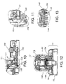
- FIG. 11 is an enlarged sectional view of the area within line XI in FIG. 10 ;
- FIG. 12 is a sectional view taken along line XII-XII in FIG. 9 ;
- FIG. 13 is an enlarged sectional view of the area within line XIII in FIG. 12 ;
- FIG. 14 is a view similar to FIG. 1 but showing the cradle teetered to the open position
- FIG. 15 is a sectional view similar to FIG. 9 but showing the cradle teetered to the open position.
- a color measurement instrument constructed in accordance with a current embodiment of the invention is illustrated in the drawings and generally designated 10 .
- the instrument includes a handheld unit 12 and a docking unit 14 .
- the docking unit in turn includes a base 16 and a cradle 18 supported on the base.
- the handheld unit 12 can be docked in the docking unit 14 ( FIG. 1 ). When so docked, the instrument 10 is capable of operating as a strip reading instrument.
- the handheld unit 12 can be removed from the docking unit 14 ( FIG. 2 ). When undocked, the handheld unit 12 is capable of operating as a spot reading instrument.
- the handheld unit 12 includes a housing 20 , a flip-down target system 22 , and a self-storing calibration plaque assembly 24 .
- the flip-down target system is movable between a stored position illustrated in FIGS. 5 and 7 when the unit is to be used as a strip reader, and an operative position illustrated in FIGS. 2 and 6 when the unit is to be used as a spot reader.
- the calibration plaque assembly is also movable between a stored position illustrated in FIGS. 5-6 , and a calibration position illustrated in FIG. 7 in which the calibration plaque is aligned with the color measurement engine for instrument calibration.
- the housing 20 includes a lower housing half 20 a and an upper housing half 20 b .
- the housing halves interfit with one another to define the housing, which encapsulates and/or supports the other components of the handheld unit 12 .
- the forward face of the housing 20 defines a storage recess 21 (see FIG. 6 ) in which the target system 22 is fitted when the target system is in the storage position (see FIGS. 5 and 7 ).
- the housing 20 also defines a finger access 23 communicating with the recess 21 to provide a point at which the target system 22 can be accessed when in the storage position.
- the housing 20 further includes a projection 25 in the lower portion of the recess 21 to cooperate with the target system 22 when in the storage position to assist in retaining the target system in the recess.
- a color measurement engine 26 is contained and supported within the housing 20 .
- the color measurement engine can be of any type generally known in the art including a spectrophotometer, a colorimeter, or a densitometer.
- the color measurement instrument 26 is a spectrophotometer of a type generally included in a variety of instruments manufactured and sold by X-Rite, Incorporated, the assignee of the present application.
- Other suitable engines are well known to those skilled in the art.
- a plurality of screws 44 extend through the lower body half 20 a and into the upper body half 20 b to intersecure the two halves and the color measurement engine 26 located therein.
- the handheld unit 12 further includes a push button 28 , a light pipe 30 , and a clear window trim plate 32 .
- the trim plate 32 is mounted in the upper portion of the upper body half 20 b and defines an aperture 34 through which the button 28 may be accessed.
- the light pipe 30 displays the current color of the status LED(s) 35 on the engine 26 .
- the push button is depressed when a strip reading measurement is to be taken.
- the lower body half 20 a includes an engine aperture 33 , a calibration arm pocket 36 , and a connection pocket 38 .
- the color measurement instrument 26 is positioned within the aperture 33 .
- the calibration arm pocket 36 defines upper and lower pairs of opposite grooved tracks 37 a and 37 b (see FIGS. 7 and 9 ) that guide the movement of the calibration assembly, which is mounted within the pocket 36 .
- the connection pocket 38 is aligned with a connection mount on the docking station 14 , and electrical connectors within the pocket 38 and on the mount interfit with one another when the handheld unit is docked in the docking station 14 .
- Within the connection pocket 38 is a catch 41 , which is engaged and secured by the latch 100 when the handheld unit is docked in the docking station 14 .
- a foot 40 is hingedly mounted to the lower body half 20 a at the lower rear corner of the housing 20 on a hinge pin 42 .
- the foot 40 provides a support for the handheld unit 10 during spot reading.
- the flip-down target system 22 includes a receiver assembly 46 and a target assembly 48 (see FIGS. 3-4 ).
- the receiver assembly 46 includes a pair of tracks 50 fixedly secured within the body 20 , and a coil spring 52 urging the target assembly 48 to its operative position as illustrated in FIGS. 2 and 6 .
- the target assembly includes a telescoping arm 54 , a foot 56 , and a reticule 58 .
- the telescoping arm 54 is fitted between and rides within the tracks 50 .
- the upper portion of the arm 54 defines a slot 60 for receiving the lower end of the spring 52 .
- the foot 56 defines an aperture 62 in which the reticule 58 is mounted in conventional fashion.
- the foot 56 is hingedly mounted on the lower end of the arm 54 on a screw 57 . The friction fit between the arm 54 and the foot 56 retains the foot 56 in the operative position unless the foot is positively moved out of the operative position.
- the target system can be moved between the stored position illustrated in FIGS. 5 and 7 and the operative position illustrated in FIGS. 2 and 6 .
- the arm 54 When in the stored position, the arm 54 is telescopically received within the housing 20 and between the tracks 50 ; and the foot 56 is rotated to fit within the foot recess 21 in the housing 20 .
- the inter-engagement of the foot 56 and the projection 25 retains the target system 22 in the storage position.
- the target system 22 can be deployed to the operative position by removing the foot 56 from the pocket 21 .
- the foot 56 can be pushed from the pocket 22 at the finger access 23 and manually rotated approximately 270 degrees with respect to the arm 54 until the foot is in the operative position; and the spring 52 ( FIGS. 3-4 ) pushes the arm 54 to its fully extended position.
- the calibration arm assembly 24 includes an arm 66 , a calibration plaque or reference color 68 , and four spring-loaded detent buttons 70 .
- the arm 66 is generally L-shaped when viewed from the side.
- the vertical leg of the L supports the four detent buttons 70 with two—one above the other—on each side.
- the horizontal leg of the L defines an upwardly opening pocket 72 in which the calibration plaque 68 is secured.
- the two upper detent buttons ride in the tracks 37 a
- the two lower detent buttons ride in the tracks 37 b , to define the travel path of the arm as the calibration assembly 24 moves between its storage position ( FIGS. 5-6 ) and its calibration position ( FIG. 7 ).
- the calibration assembly can be moved to a cleaning position (not shown) between the storage position and the calibration position in which the assembly extends generally perpendicularly from the body 20 .
- the lower detents 70 must be moved outside of the lower track 37 b to move the calibration assembly to the cleaning position.
- the calibration plaque 68 is easily viewable and accessible in the cleaning position. Additionally, the assembly 24 may be separated from the housing 20 altogether for service or replacement.
- the docking unit includes a base 16 and a cradle 18 supported in teeter-totter fashion on the base.
- the base 16 includes a base body 80 , a plurality of idler rollers 82 , and a backer 84 .
- the base body 80 defines a lock-receiving aperture 94 and includes a plurality of integrally molded flexible arms 88 . Each arm supports one of the idler rollers 82 .
- the backer 84 is mounted on the underside of the base body 80 and is aligned with the race-track shaped aperture 90 to provide a selectable backer color and/or material for the color measurement engine 26 .
- the base body 80 also includes a fulcrum or teeter platform 92 .
- a pair of locator pins 96 extend upwardly from the teeter platform 92 to interfit with the cradle 18 .
- the cradle 18 includes a base plate 120 , a drive assembly, a cover 122 , and a lock assembly 86 .
- the base plate 120 defines a pocket 124 , an engine pocket 126 , roller openings 128 , drive shaft pocket 130 , and shaft drive wheel openings 131 .
- the engine pocket 126 provides a physical reference to register with the optical portion of the color measurement instrument 26 .
- a pair of idler rollers 132 are supported in the idler roller pockets 128 for engagement with the corresponding idler rollers 82 in the base body 80 .
- the base plate 120 further defines locator apertures 133 that interfit with the pins 96 on the base 16 to properly locate the cradle 18 on the base.
- the base plate rests on the fulcrum or teeter platform 92 on the base 16 .
- the drive assembly includes a drive shaft 134 and a motor 136 for selectively driving the shaft.
- the drive shaft 134 includes a plurality of O-rings 138 which act as wheels or tires.
- the drive shaft 134 is mounted in the drive shaft pocket 130 so that the O-rings 138 are located within the drive shaft wheel openings 131 to extend from the underside of the base plate 120 .
- a pair of journals 140 are secured to the base plate 120 over the drive shaft 134 to retain the drive shaft in position.
- An electrical connector 142 is mounted on a pair of studs 144 to provide electrical connection with the handheld unit 12 when the handheld unit is docked in the docking unit 14 .
- the cover 122 defines a button opening 150 and a cradle opening 152 , and includes an electrical connector mount 154 .
- a toe 155 extends into the cradle opening from the forward portion of the cradle opening to cooperate with the projection 25 on the handheld unit 12 to secure the handheld unit in the docking station.
- the lock mechanism 86 includes a body 98 , a latch 100 , and an actuator arm 102 .
- the body 98 is secured to the base plate 120 .
- the latch 100 is hingedly connected to the body 98 on a hinge pin 104 .
- the actuator arm 102 includes a button 106 located within the aperture 150 , and a remote end 108 engaging the latch 100 .
- the latch interfits with and releasably secures the catch 41 on the housing 20 when the handheld unit 12 is docked in the docking unit 14 .
- the button 106 When the button 106 is depressed, the arm 108 pushes the latch 100 to disengage the catch 41 .
- FIGS. 9-13 are sectional views of the handheld unit 12 docked or secured within the docking unit 14 .
- the projection 25 on the handheld unit 12 is positioned under the toe 155 on the cover 122 , and the catch 41 is secured by the latch 100 .
- the instrument 10 can be used as either a strip reading instrument or a spot reading instrument.
- the handheld unit 12 is docked in the docking unit 14 .
- the projection 25 on the forward portion of the handheld unit 12 is positioned under the toe 155 on the cradle cover 122 .
- the heel of the instrument is then pressed downwardly until the latch 100 fits over and secures the catch 41 .
- the instrument 10 When so docked, the instrument 10 can be operated as a strip reading instrument in a manner generally similar to that described in U.S. Pat. No. 6,198,536 by actuating the button 28 . Specifically, the motor 136 is actuated to rotate the shaft 134 . A strip is inserted between the base 16 and the cradle 18 . The wheels 138 on the drive shaft 134 draw the sample through the instrument past the color measurement engine 26 . The engine samples the strip at locations along the strip to make color measurements.
- the control and color measurement software required to operate the instrument 10 as a strip reader are well known to those skilled in the art.
- the handheld unit 12 is removed or undocked from the docking unit 14 . More specifically, the button 106 is depressed so that the latch 100 releases the catch 41 . This permits the heel of the handheld unit 12 to be raised and subsequently the projection 25 to be removed from under the toe 155 .
- the handheld unit 12 When removed from the docking unit, the handheld unit 12 can be used as a spot reader.
- the flip-down target system 22 is deployed from the storage position to the operative position by removing the foot 56 from the recess 21 in the forward portion of the body 20 .
- the target arm 54 Under the influence of the spring 52 , the target arm 54 extends from the body 20 .
- the user manually rotates the foot 56 approximately 270 degrees to place the target system in the operative position as illustrated in FIGS. 2 and 6 .
- the unit 12 is ready for spot reading.
- the reticule 58 in the foot 56 is aligned with a spot or target area to be measured.
- FIGS. 14 and 15 are similar to FIGS. 1 and 9 , respectively. However, they show the cradle 18 rocked or teetered to lift the handheld unit 12 from the idler rollers 82 and thereby open the sample strip area. This teetering or lifting is accomplished applying manual downward pressure to the right end or portion of the cradle 18 (when viewed as in FIGS. 14-15 ). This rocks or teeters the cradle about the fulcrum platform 92 (see FIG. 3 ) so that the left portion of the cradle 18 rises above the base 16 . This motion lifts the handheld unit 12 from the base 16 permitting (a) unusually thick or thin sample media to be loaded, (b) sample jams to be corrected, (c) sample alignment be corrected or adjusted, and (d) the sample transportation area to be visually inspected.
Abstract
Description
Claims (6)
Priority Applications (1)
| Application Number | Priority Date | Filing Date | Title |
|---|---|---|---|
| US11/116,866 US7322527B2 (en) | 2004-04-30 | 2005-04-28 | Color measurement instrument capable of both strip reading and spot reading |
Applications Claiming Priority (2)
| Application Number | Priority Date | Filing Date | Title |
|---|---|---|---|
| US56741604P | 2004-04-30 | 2004-04-30 | |
| US11/116,866 US7322527B2 (en) | 2004-04-30 | 2005-04-28 | Color measurement instrument capable of both strip reading and spot reading |
Publications (2)
| Publication Number | Publication Date |
|---|---|
| US20050242191A1 US20050242191A1 (en) | 2005-11-03 |
| US7322527B2 true US7322527B2 (en) | 2008-01-29 |
Family
ID=34968488
Family Applications (1)
| Application Number | Title | Priority Date | Filing Date |
|---|---|---|---|
| US11/116,866 Active 2025-11-18 US7322527B2 (en) | 2004-04-30 | 2005-04-28 | Color measurement instrument capable of both strip reading and spot reading |
Country Status (4)
| Country | Link |
|---|---|
| US (1) | US7322527B2 (en) |
| DE (1) | DE112005000969T5 (en) |
| GB (1) | GB2429072A (en) |
| WO (1) | WO2005106414A1 (en) |
Cited By (3)
| Publication number | Priority date | Publication date | Assignee | Title |
|---|---|---|---|---|
| USD846415S1 (en) * | 2017-07-12 | 2019-04-23 | Byk-Gardner Gmbh | Colorimeter |
| USD846417S1 (en) * | 2017-07-12 | 2019-04-23 | Byk-Gardner Gmbh | Colorimeter |
| USD846416S1 (en) * | 2017-07-12 | 2019-04-23 | Byk-Gardner Gmbh | Colorimeter |
Families Citing this family (6)
| Publication number | Priority date | Publication date | Assignee | Title |
|---|---|---|---|---|
| US8284400B1 (en) * | 2011-04-01 | 2012-10-09 | X-Rite Europe Gmbh | Hand-held color measurement device |
| DE102017211067A1 (en) * | 2017-06-29 | 2019-01-03 | Byk-Gardner Gmbh | Receiving device for a surface measuring device |
| USD949032S1 (en) * | 2019-11-27 | 2022-04-19 | Byk-Gardner Gmbh | Color appearance measurement instrument |
| USD949713S1 (en) * | 2019-11-27 | 2022-04-26 | Byk-Gardner Gmbh | Appearance measurement instrument |
| JP2022162656A (en) * | 2021-04-13 | 2022-10-25 | セイコーエプソン株式会社 | Color measuring device |
| EP4206627A1 (en) * | 2021-12-29 | 2023-07-05 | X-Rite, Inc. | A color measurement system comprising a calibration plaque |
Citations (12)
| Publication number | Priority date | Publication date | Assignee | Title |
|---|---|---|---|---|
| US4538072A (en) * | 1982-04-20 | 1985-08-27 | Siemens Aktiengesellschaft | Optical wand for reading OCR characters and bar code marks |
| US5646735A (en) | 1994-10-07 | 1997-07-08 | Krzyminski; Harald | Hand-held instrument for reflection measuring of optical density and color on printed sheets |
| US5814804A (en) * | 1992-11-13 | 1998-09-29 | Psc Inc. | Optical scanner activated with position locator |
| US5844681A (en) | 1996-07-17 | 1998-12-01 | Lucid Inc | Spectral densitometer |
| US5955719A (en) * | 1997-12-19 | 1999-09-21 | A. T. Cross Company | Data/pen well |
| US6061140A (en) * | 1999-05-27 | 2000-05-09 | X-Rite, Incorporated | Spectrophotometer with selectable measurement area |
| US20010015806A1 (en) | 1999-07-02 | 2001-08-23 | X-Rite, Incorporated | Portable scanning spectrophotometer |
| US20020005950A1 (en) * | 2000-02-04 | 2002-01-17 | Beimers Daniel J. | Handheld color measurement instrument |
| US6362886B2 (en) * | 2000-02-07 | 2002-03-26 | Applied Color Systems | Portable color measuring device |
| US20020036778A1 (en) * | 2000-09-28 | 2002-03-28 | Gregg Wagner | Handheld, portable color measuring device with display |
| US20030071998A1 (en) * | 2001-10-04 | 2003-04-17 | Krupka F. Jeffrey | Color measurement device |
| US7070110B2 (en) * | 2003-04-07 | 2006-07-04 | Silverbrook Research Pty Ltd | Hand-wearable coded data reader |
-
2005
- 2005-04-28 WO PCT/IB2005/051400 patent/WO2005106414A1/en active Application Filing
- 2005-04-28 DE DE112005000969T patent/DE112005000969T5/en not_active Withdrawn
- 2005-04-28 US US11/116,866 patent/US7322527B2/en active Active
- 2005-04-28 GB GB0620515A patent/GB2429072A/en not_active Withdrawn
Patent Citations (13)
| Publication number | Priority date | Publication date | Assignee | Title |
|---|---|---|---|---|
| US4538072A (en) * | 1982-04-20 | 1985-08-27 | Siemens Aktiengesellschaft | Optical wand for reading OCR characters and bar code marks |
| US5814804A (en) * | 1992-11-13 | 1998-09-29 | Psc Inc. | Optical scanner activated with position locator |
| US5646735A (en) | 1994-10-07 | 1997-07-08 | Krzyminski; Harald | Hand-held instrument for reflection measuring of optical density and color on printed sheets |
| US5844681A (en) | 1996-07-17 | 1998-12-01 | Lucid Inc | Spectral densitometer |
| US5955719A (en) * | 1997-12-19 | 1999-09-21 | A. T. Cross Company | Data/pen well |
| US6061140A (en) * | 1999-05-27 | 2000-05-09 | X-Rite, Incorporated | Spectrophotometer with selectable measurement area |
| US20010015806A1 (en) | 1999-07-02 | 2001-08-23 | X-Rite, Incorporated | Portable scanning spectrophotometer |
| US20020005950A1 (en) * | 2000-02-04 | 2002-01-17 | Beimers Daniel J. | Handheld color measurement instrument |
| US6362886B2 (en) * | 2000-02-07 | 2002-03-26 | Applied Color Systems | Portable color measuring device |
| US20020036778A1 (en) * | 2000-09-28 | 2002-03-28 | Gregg Wagner | Handheld, portable color measuring device with display |
| US6285452B1 (en) * | 2000-11-01 | 2001-09-04 | X-Rite Incorporated | Portable scanning spectrophotometer |
| US20030071998A1 (en) * | 2001-10-04 | 2003-04-17 | Krupka F. Jeffrey | Color measurement device |
| US7070110B2 (en) * | 2003-04-07 | 2006-07-04 | Silverbrook Research Pty Ltd | Hand-wearable coded data reader |
Non-Patent Citations (1)
| Title |
|---|
| Spectrolino Spectrophotometer, The Handheld System That Scores High In Color Measurement Precision (GretagMacbeth). |
Cited By (3)
| Publication number | Priority date | Publication date | Assignee | Title |
|---|---|---|---|---|
| USD846415S1 (en) * | 2017-07-12 | 2019-04-23 | Byk-Gardner Gmbh | Colorimeter |
| USD846417S1 (en) * | 2017-07-12 | 2019-04-23 | Byk-Gardner Gmbh | Colorimeter |
| USD846416S1 (en) * | 2017-07-12 | 2019-04-23 | Byk-Gardner Gmbh | Colorimeter |
Also Published As
| Publication number | Publication date |
|---|---|
| GB2429072A (en) | 2007-02-14 |
| DE112005000969T5 (en) | 2007-03-29 |
| GB0620515D0 (en) | 2006-12-06 |
| US20050242191A1 (en) | 2005-11-03 |
| WO2005106414A1 (en) | 2005-11-10 |
Similar Documents
| Publication | Publication Date | Title |
|---|---|---|
| US7322527B2 (en) | Color measurement instrument capable of both strip reading and spot reading | |
| CN204405185U (en) | Handheld analyzer | |
| US7791027B2 (en) | Apparatus and method providing a hand-held spectrometer | |
| US6198536B1 (en) | Portable scanning spectrophotometer | |
| US10203246B2 (en) | Systems and methods for calibration of a handheld spectrometer | |
| US11517219B2 (en) | Biological information measurement apparatus | |
| US4833088A (en) | Reagent strip handling mechanism | |
| EP3084374B1 (en) | Visual indicator of scan workflow | |
| US4798705A (en) | Compact analyzer | |
| JP2006526788A (en) | Verification apparatus and method for optical inspection equipment | |
| USRE40768E1 (en) | Optical inspection apparatus with removable inserts | |
| US9658152B2 (en) | Optical interpretation of assay results | |
| US10900910B2 (en) | Reagent card alignment method for sample dispensing | |
| EP2751533A1 (en) | Color measurement apparatus | |
| US6346984B2 (en) | Portable scanning spectrophotometer | |
| JPH04230813A (en) | Scanning concentration meter | |
| WO2007111379A1 (en) | Method for measuring color of object and color measuring device | |
| WO2013163420A1 (en) | Spectrometer with built-in atr and accessory compartment | |
| US11428640B2 (en) | Urine test device | |
| JP5534044B2 (en) | Alignment apparatus and reflection characteristic measurement system | |
| US20060257284A1 (en) | Verification device and method for optical inspection machine | |
| JPH09127120A (en) | Analyzer | |
| CN219625349U (en) | Portable dustproof ultraviolet visible photometer | |
| TWI748164B (en) | Screening test paper reading system | |
| WO2000012982A1 (en) | Portable scanning spectrophotometer |
Legal Events
| Date | Code | Title | Description |
|---|---|---|---|
| AS | Assignment |
Owner name: X-RITE, INCORPORATED, MICHIGAN Free format text: ASSIGNMENT OF ASSIGNORS INTEREST;ASSIGNORS:BAKER, DOUGLAS V.;WEBER, MICHAEL J.;SUTTON, TODD A.;AND OTHERS;REEL/FRAME:016524/0048 Effective date: 20050428 |
|
| AS | Assignment |
Owner name: GOLDMAN SACHS CREDIT PARTNERS L.P., NEW YORK Free format text: PATENT SECURITY AGREEMENT (FIRST LIEN);ASSIGNOR:X-RITE, INCORPORATED;REEL/FRAME:017097/0263 Effective date: 20060131 Owner name: GOLDMAN SACHS CREDIT PARTNERS L.P., NEW YORK Free format text: PATENT SECURITY AGREEMENT (SECOND LIEN);ASSIGNOR:X-RITE, INCORPORATED;REEL/FRAME:017097/0337 Effective date: 20060131 |
|
| AS | Assignment |
Owner name: FIFTH THIRD BANK, OHIO Free format text: ASSIGNMENT OF PATENT SECURITY AGREEMENT;ASSIGNOR:GOLDMAN SACHS CREDIT PARTNERS, L.P.;REEL/FRAME:018171/0167 Effective date: 20060630 |
|
| AS | Assignment |
Owner name: FIFTH THIRD BANK, A MICHIGAN BANKING CORPORATION, Free format text: SECURITY AGREEMENT;ASSIGNORS:X-RITE, INCORPORATED;OTP, INCORPORATED;MONACO ACQUISITION COMPANY;AND OTHERS;REEL/FRAME:020064/0313 Effective date: 20071024 |
|
| AS | Assignment |
Owner name: THE BANK OF NEW YORK, AS COLLATERAL AGENT, NEW YOR Free format text: PATENT SECURITY AGREEMENT (SECOND LIEN);ASSIGNOR:X-RITE, INCORPORATED;REEL/FRAME:020156/0569 Effective date: 20071024 |
|
| STCF | Information on status: patent grant |
Free format text: PATENTED CASE |
|
| AS | Assignment |
Owner name: X-RITE INCORPORATED, MICHIGAN Free format text: RELEASE BY SECURED PARTY;ASSIGNOR:GOLDMAN SACHS CREDIT PARTNERS L.P., AS COLLATERAL AGENT;REEL/FRAME:020845/0285 Effective date: 20071024 |
|
| AS | Assignment |
Owner name: X-RITE, INCORPORATED, MICHIGAN Free format text: PATENT RELEASE AND REASSIGNMENT FOR THE PATENT SECURITY AGREEMENT ORIGINALLY RECORDED AT REEL 017097, FRAME 0263 AND ASSIGNED AT REEL 018171, FRAME 0167;ASSIGNORS:FIFTH THIRD BANK;GOLDMAN SACHS CREDIT PARTNERS L.P.;REEL/FRAME:021029/0554 Effective date: 20071024 |
|
| AS | Assignment |
Owner name: THE BANK OF NEW YORK MELLON (F/K/A THE BANK OF NEW Free format text: AFTER-ACQUIRED PATENT SECURITY AGREEMENT (SECOND LIEN);ASSIGNOR:X-RITE, INCORPORATED;REEL/FRAME:021744/0582 Effective date: 20081028 Owner name: FIFTH THIRD BANK, A MICHIGAN BANKING CORPORATION, Free format text: AFTER-ACQUIRED PATENT SECURITY AGREEMENT (FIRST LIEN)- FIRST SUPPLEMENTAL FILING;ASSIGNOR:X-RITE, INCORPORATED;REEL/FRAME:021744/0267 Effective date: 20081028 |
|
| FEPP | Fee payment procedure |
Free format text: PAYER NUMBER DE-ASSIGNED (ORIGINAL EVENT CODE: RMPN); ENTITY STATUS OF PATENT OWNER: LARGE ENTITY Free format text: PAYOR NUMBER ASSIGNED (ORIGINAL EVENT CODE: ASPN); ENTITY STATUS OF PATENT OWNER: LARGE ENTITY |
|
| AS | Assignment |
Owner name: BANK OF AMERICA, N.A., AS ADMINISTRATIVE AGENT, TE Free format text: NOTICE OF GRANT OF SECURITY INTEREST IN PATENTS;ASSIGNOR:X-RITE, INCORPORATED;REEL/FRAME:026082/0713 Effective date: 20110330 |
|
| AS | Assignment |
Owner name: X-RITE, INCORPORATED, MICHIGAN Free format text: RELEASE BY SECURED PARTY;ASSIGNOR:THE BANK OF NEW YORK MELLON, AS AGENT;REEL/FRAME:026114/0265 Effective date: 20101001 Owner name: GRETAGMACBETH, LLC, MICHIGAN Free format text: RELEASE BY SECURED PARTY;ASSIGNOR:THE BANK OF NEW YORK MELLON, AS AGENT;REEL/FRAME:026114/0265 Effective date: 20101001 |
|
| AS | Assignment |
Owner name: X-RITE GLOBAL, INCORPORATED, MICHIGAN Free format text: PATENT RELEASE AND REASSIGNMENT;ASSIGNOR:FIFTH THIRD BANK, AN OHIO BANKING CORPORATION, AND SUCCESSOR BY MERGER TO FIFTH THIRD BANK, A MICHIGAN BANKING CORPORATION, AS COLLATERAL AGENT;REEL/FRAME:026126/0496 Effective date: 20110330 Owner name: PANTONE, INC., NEW JERSEY Free format text: PATENT RELEASE AND REASSIGNMENT;ASSIGNOR:FIFTH THIRD BANK, AN OHIO BANKING CORPORATION, AND SUCCESSOR BY MERGER TO FIFTH THIRD BANK, A MICHIGAN BANKING CORPORATION, AS COLLATERAL AGENT;REEL/FRAME:026126/0496 Effective date: 20110330 Owner name: X-RITE HOLDINGS, INC., MICHIGAN Free format text: PATENT RELEASE AND REASSIGNMENT;ASSIGNOR:FIFTH THIRD BANK, AN OHIO BANKING CORPORATION, AND SUCCESSOR BY MERGER TO FIFTH THIRD BANK, A MICHIGAN BANKING CORPORATION, AS COLLATERAL AGENT;REEL/FRAME:026126/0496 Effective date: 20110330 Owner name: X-RITE, INCORPORATED, MICHIGAN Free format text: PATENT RELEASE AND REASSIGNMENT;ASSIGNOR:FIFTH THIRD BANK, AN OHIO BANKING CORPORATION, AND SUCCESSOR BY MERGER TO FIFTH THIRD BANK, A MICHIGAN BANKING CORPORATION, AS COLLATERAL AGENT;REEL/FRAME:026126/0539 Effective date: 20110330 Owner name: GRETAGMACBETH LLC, MICHIGAN Free format text: PATENT RELEASE AND REASSIGNMENT;ASSIGNOR:FIFTH THIRD BANK, AN OHIO BANKING CORPORATION, AND SUCCESSOR BY MERGER TO FIFTH THIRD BANK, A MICHIGAN BANKING CORPORATION, AS COLLATERAL AGENT;REEL/FRAME:026126/0496 Effective date: 20110330 Owner name: X-RITE, INCORPORATED, MICHIGAN Free format text: PATENT RELEASE AND REASSIGNMENT;ASSIGNOR:FIFTH THIRD BANK, AN OHIO BANKING CORPORATION, AND SUCCESSOR BY MERGER TO FIFTH THIRD BANK, A MICHIGAN BANKING CORPORATION, AS COLLATERAL AGENT;REEL/FRAME:026126/0496 Effective date: 20110330 Owner name: MONACO ACQUISITION COMPANY, MICHIGAN Free format text: PATENT RELEASE AND REASSIGNMENT;ASSIGNOR:FIFTH THIRD BANK, AN OHIO BANKING CORPORATION, AND SUCCESSOR BY MERGER TO FIFTH THIRD BANK, A MICHIGAN BANKING CORPORATION, AS COLLATERAL AGENT;REEL/FRAME:026126/0496 Effective date: 20110330 Owner name: OTP, INCORPORATED, MICHIGAN Free format text: PATENT RELEASE AND REASSIGNMENT;ASSIGNOR:FIFTH THIRD BANK, AN OHIO BANKING CORPORATION, AND SUCCESSOR BY MERGER TO FIFTH THIRD BANK, A MICHIGAN BANKING CORPORATION, AS COLLATERAL AGENT;REEL/FRAME:026126/0496 Effective date: 20110330 Owner name: GRETAGMACBETH LLC, MICHIGAN Free format text: PATENT RELEASE AND REASSIGNMENT;ASSIGNOR:FIFTH THIRD BANK, AN OHIO BANKING CORPORATION, AND SUCCESSOR BY MERGER TO FIFTH THIRD BANK, A MICHIGAN BANKING CORPORATION, AS COLLATERAL AGENT;REEL/FRAME:026126/0539 Effective date: 20110330 |
|
| AS | Assignment |
Owner name: X-RITE GLOBAL, INCORPORATED, MICHIGAN Free format text: RELEASE BY SECURED PARTY;ASSIGNOR:THE BANK OF NEW YORK MELLON, AS AGENT;REEL/FRAME:026149/0681 Effective date: 20101001 Owner name: MONACO ACQUISITION COMPANY, MICHIGAN Free format text: RELEASE BY SECURED PARTY;ASSIGNOR:THE BANK OF NEW YORK MELLON, AS AGENT;REEL/FRAME:026149/0681 Effective date: 20101001 Owner name: GRETAGMACBETH, LLC, MICHIGAN Free format text: RELEASE BY SECURED PARTY;ASSIGNOR:THE BANK OF NEW YORK MELLON, AS AGENT;REEL/FRAME:026149/0681 Effective date: 20101001 Owner name: X-RITE, INCORPORATED, MICHIGAN Free format text: RELEASE BY SECURED PARTY;ASSIGNOR:THE BANK OF NEW YORK MELLON, AS AGENT;REEL/FRAME:026149/0681 Effective date: 20101001 Owner name: OTP, INCORPORATED, MICHIGAN Free format text: RELEASE BY SECURED PARTY;ASSIGNOR:THE BANK OF NEW YORK MELLON, AS AGENT;REEL/FRAME:026149/0681 Effective date: 20101001 Owner name: X-RITE HOLDINGS, INC., MICHIGAN Free format text: RELEASE BY SECURED PARTY;ASSIGNOR:THE BANK OF NEW YORK MELLON, AS AGENT;REEL/FRAME:026149/0681 Effective date: 20101001 Owner name: PANTONE, INC., NEW JERSEY Free format text: RELEASE BY SECURED PARTY;ASSIGNOR:THE BANK OF NEW YORK MELLON, AS AGENT;REEL/FRAME:026149/0681 Effective date: 20101001 |
|
| FPAY | Fee payment |
Year of fee payment: 4 |
|
| AS | Assignment |
Owner name: X-RITE, INC., MICHIGAN Free format text: TERMINATION AND RELEASE OF SECURITY INTEREST IN PATENTS RECORDED ON REEL 026082 FRAME 0713;ASSIGNOR:BANK OF AMERICA, N.A., AS ADMINISTRATIVE AGENT;REEL/FRAME:028218/0671 Effective date: 20120515 |
|
| FPAY | Fee payment |
Year of fee payment: 8 |
|
| MAFP | Maintenance fee payment |
Free format text: PAYMENT OF MAINTENANCE FEE, 12TH YEAR, LARGE ENTITY (ORIGINAL EVENT CODE: M1553); ENTITY STATUS OF PATENT OWNER: LARGE ENTITY Year of fee payment: 12 |