US7318576B2 - Bi-directional air valve for a tank system of a motor vehicle - Google Patents
Bi-directional air valve for a tank system of a motor vehicle Download PDFInfo
- Publication number
- US7318576B2 US7318576B2 US11/139,401 US13940105A US7318576B2 US 7318576 B2 US7318576 B2 US 7318576B2 US 13940105 A US13940105 A US 13940105A US 7318576 B2 US7318576 B2 US 7318576B2
- Authority
- US
- United States
- Prior art keywords
- motor
- valve
- closure element
- axle
- air valve
- Prior art date
- Legal status (The legal status is an assumption and is not a legal conclusion. Google has not performed a legal analysis and makes no representation as to the accuracy of the status listed.)
- Expired - Fee Related, expires
Links
Images


Classifications
-
- F—MECHANICAL ENGINEERING; LIGHTING; HEATING; WEAPONS; BLASTING
- F16—ENGINEERING ELEMENTS AND UNITS; GENERAL MEASURES FOR PRODUCING AND MAINTAINING EFFECTIVE FUNCTIONING OF MACHINES OR INSTALLATIONS; THERMAL INSULATION IN GENERAL
- F16K—VALVES; TAPS; COCKS; ACTUATING-FLOATS; DEVICES FOR VENTING OR AERATING
- F16K31/00—Actuating devices; Operating means; Releasing devices
- F16K31/44—Mechanical actuating means
- F16K31/52—Mechanical actuating means with crank, eccentric, or cam
- F16K31/524—Mechanical actuating means with crank, eccentric, or cam with a cam
- F16K31/52408—Mechanical actuating means with crank, eccentric, or cam with a cam comprising a lift valve
- F16K31/52441—Mechanical actuating means with crank, eccentric, or cam with a cam comprising a lift valve with a pivoted disc or flap
-
- F—MECHANICAL ENGINEERING; LIGHTING; HEATING; WEAPONS; BLASTING
- F16—ENGINEERING ELEMENTS AND UNITS; GENERAL MEASURES FOR PRODUCING AND MAINTAINING EFFECTIVE FUNCTIONING OF MACHINES OR INSTALLATIONS; THERMAL INSULATION IN GENERAL
- F16K—VALVES; TAPS; COCKS; ACTUATING-FLOATS; DEVICES FOR VENTING OR AERATING
- F16K31/00—Actuating devices; Operating means; Releasing devices
- F16K31/02—Actuating devices; Operating means; Releasing devices electric; magnetic
- F16K31/04—Actuating devices; Operating means; Releasing devices electric; magnetic using a motor
- F16K31/047—Actuating devices; Operating means; Releasing devices electric; magnetic using a motor characterised by mechanical means between the motor and the valve, e.g. lost motion means reducing backlash, clutches, brakes or return means
-
- F—MECHANICAL ENGINEERING; LIGHTING; HEATING; WEAPONS; BLASTING
- F16—ENGINEERING ELEMENTS AND UNITS; GENERAL MEASURES FOR PRODUCING AND MAINTAINING EFFECTIVE FUNCTIONING OF MACHINES OR INSTALLATIONS; THERMAL INSULATION IN GENERAL
- F16K—VALVES; TAPS; COCKS; ACTUATING-FLOATS; DEVICES FOR VENTING OR AERATING
- F16K31/00—Actuating devices; Operating means; Releasing devices
- F16K31/44—Mechanical actuating means
- F16K31/52—Mechanical actuating means with crank, eccentric, or cam
- F16K31/524—Mechanical actuating means with crank, eccentric, or cam with a cam
- F16K31/52408—Mechanical actuating means with crank, eccentric, or cam with a cam comprising a lift valve
Definitions
- the invention concerns a bidirectional air valve for a tank system of a motor vehicle.
- Such valves normally possess one inlet port, one outlet port, a seat located therebetween and a closure element, which closure element, when in its closed position, blocks the flowing connection between the inlet and the outlet ports and frees the same when in its opened position.
- problems continually arising in the desired entry or exit of air have not been satisfactorily resolved.
- certain fuel tanks which have been provided with so-called air venting devices to act during the filling of fuel tanks, release a mixture of air and vaporized fuel (hereinafter, referred to as “gas”) to the atmosphere through the vent of an activated carbon filter.
- a float operated valve for control of gas release during the filling of a tank, a float operated valve is provided, affixed to or near an upper tank wall, which said valve, in a case of rising fuel level, shuts itself off at a predetermined fuel level. Subsequently, upon continued filling with even more fuel, a pressure in the tank is created, which finally leads to shut-off of an inserted fuel-input nozzle.
- the fuel level drops to a threshold level, wherein, from that point on, the tank air release valve remains open.
- fuel vapors created by effusion or by an increase in temperature, inevitably migrate to the active carbon filter, thus reducing the adsorbancy capability of the latter.
- a further problem is, that during the driving operation of the motor vehicle, possibly on a curving street in the summer time, severe fuel back-wash within the fuel tank, brings about an increased generation of fuel vapors, especially if the fuel is gasoline. Accordingly, the pressure within the fuel tank causes a correspondingly concentrated emission of gas, which transports itself to the active carbon filter in the form of droplets, which quickly saturate the said filter.
- the purpose of the invention is, to propose a two-directional valve for the tank system of a motor vehicle, with which the above described, and similar problems, can be avoided.
- This purpose is achieved by a two directional valve, the closure element of which can be displaced in optional intervening positions with the aid of a motor.
- a valve of this type offers, besides a shut-off function, also the possibility of controlling and/or regulating a gas flow which is introduced into a tank, or is removed therefrom.
- a pressure sensor it is possible, with the aid of a pressure sensor to create a pressure related regulation of the release of the defined gas from the tank, in such a manner that the valve, during the driving operation of the vehicle can only be opened at a predetermined positive pressure in the tank, that is, in case this was desired at the beginning of the tank filling process.
- the closure element is not brought into its open position, in which a flow of gas from the tank chamber can escape nearly without hindrance.
- the closure element would, in such a case, most likely have been moved into an intermediate location, in which the cross sectional through-put of the valve was only partially available.
- the quantity of gas flowing out of the tank can be specifically reduced in accord with the intensity of that pressure and in this state, be conveyed to an activated carbon filter.
- An invented valve can, obviously, be installed as a check valve, in order, for example, to block the outlet vent of the activated carbon filter, which vent is open to the atmosphere.
- a step-down transmission is provided, which, first, is coupled with a drive element of the motor and second, is movably connected with the closure element.
- the resonance body would be so coupled with a step-down element so that its vibrations could be transformed into a linear or a rotational motion of a transmission component.
- piezo-motors are employed, these being that type of a vibration motor, wherein the resonance body, with the aid of a piezo electrical output means, can be set into vibratory motion.
- FIG. 1 a longitudinal presentation of a first embodiment example of a bidirectional air release valve
- FIG. 2 a perspective, sectional, longitudinal presentation of a second embodiment example of a bidirectional air release valve
- FIG. 3 a perspective, sectional, longitudinal presentation of a third embodiment example of a bidirectional air release valve
- FIG. 4 in perspective, details of principally a valve stem 35 and a rotational part 34 of the embodiment shown in FIG. 3 ,
- FIG. 5 a perspective, sectional, longitudinal presentation of a fourth embodiment example of a bidirectional air release valve
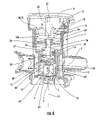
- FIG. 6 a perspective, sectional, longitudinal presentation of a fifth embodiment example of a bidirectional air release valve.
- valves which are shown consist of respectively, an essentially cylindrical housing 1 , which—as seen in the installed condition—has on its underside an inlet port 2 and on its side, an outlet port 3 . Further the valve possesses a valve seat, which encompasses the said inlet port 2 , a closure element 5 which coacts with the valve seat 4 , and a motor.
- the motor is, specifically, a piezo-motor 6 with a step-down transmission element 7 , the one side of which is movably coupled with the said piezo-motor 6 , and indeed in such a manner, that the closure element 5 is movable between, first, a closed position, in which it shuts off the inlet opening 2 and second, an open position, in which it releases said closure of the inlet opening 2 , which simultaneously frees an internal flow path from the inlet port to the outlet port.
- the said essentially cylindrically designed housing 1 possesses on its upper end, an opening, in which is inserted a cup-shaped, insert 9 , which is closed by a top cover 8 .
- the valve housing 1 is closed by a bottom 10 , which is penetrated by the inlet port 2 .
- the valve seat is located above the level of the plane of the said bottom 10 in the direction of the central, axis 12 of the valve seat 4 .
- the piezo-motor 6 is to be found proximal to the top cover 8 .
- the piezo-motor 6 assembly includes one resonance body 16 , an end 17 of which is affixed in the top cover 8 via an arm-spring 18 aided by a set screw 19 .
- the construction of the piezo-motor 6 includes also an alternating current controlled piezo crystal 6 a , which has been placed in the resonance body 16 .
- the piezo-crystal initiates the vibration of the resonance body 16 .
- the other end 24 of the resonance body 16 acts with the step-down transmission 7 in the manner of a drive.
- the step-down transmissions 7 a , 7 b are, essentially, formed by an activation lever 20 , 20 a.
- the activation lever 20 , 20 a is, in fact, a somewhat plate shaped, longitudinally extended piece, and the end 22 thereof is proximal to the valve seat. This said end 22 is pivotally placed about a first pivot axle 23 , 23 a , which axle extends itself external to the valve seat 4 and runs parallel to the plane thereof. At the end 22 of the activation lever 20 , 20 a is affixed the closure element 5 , which coacts with the valve seat 4 .
- the closure element 5 must also pivot to the left, as can be inferred from FIG. 1 .
- the velocity of the pivoting movement of the activation lever 20 is, in this arrangement, so great, that the closure element 5 , within fractions of a second, can be displaced from its closed position into its opened position.
- a piezo-motor 6 of the described kind can be acquired from Elliptec, AG, D-44379 Dortmund.
- the closure element is likewise molded on the lower end of an activation lever 20 a .
- This said lever is not directly subjected to power from a piezo-motor 6 , but rather a two arm lever 26 is interposed between the activation lever 20 a and the piezo-motor 6 .
- This said lever 26 is rotationally supported on a second pivotal axis 27 , which runs parallel to the first pivotal axis 23 .
- the pivotal axle 27 is placed more nearly in the mid section of the housing 1 , to allow it to intercept the central, longitudinal axis 12 of the valve seat 4 .
- That arm of the lever 26 which is proximal to the piezo-motor is designed as a circular disc segment 21 , the edge face thereof, which is coaxial to the pivotal axle 27 , forms that surface which is to coact with the end surface 24 of the piezo-motor 6 .
- the second arm of the lever 26 consists of two partial arms 28 , which are separated from one another along the length of the pivotal axle 27 .
- the free ends of the two partial arms 28 enclose between them the upper end 29 of the activation lever 20 a .
- the said free ends of the partial arms 28 are bound together by means of a pin 42 , which pin 42 penetrates through an extended slot 30 in the upper end 29 of the activation lever 20 a .
- the activation lever 20 a carries out a swinging motion in the direction of the arrow 33 . Taking as a starting point, the open position of the closure element 5 as seen in FIG. 2 , then this said closure element pivots to regain its closed position, in which it will lie on the valve seat 4 .
- the arrangement of FIG. 2 has the advantage, that, at the same step-down ratio, the activation lever 20 a requires a lesser space requirement in the pivoting direction, than it does in FIG. 1 . Beyond this, because of the extended slot 30 , unsatisfactory tolerance conditions between the closure element and the valve seat 4 are compensated for.
- the step-down transmission 7 includes a rotational part 34 and a valve stem 35 , which stem extends itself coaxially with the central longitudinal axis 12 and carries on its lower end, the closure element 5 .
- the rotational part 34 turns about an axle 36 (see FIG. 4 ), which runs transverse to, and intercepts the central longitudinal axis 12 .
- the rotational part 34 is, essentially, formed from two circular disks 37 , 37 a , which are separated from one another along the turning axle 36 , and encompass between them a middle area of the valve stem 35 .
- the said turning axle consists of two partial axles 36 , 36 a , which, are centrally aligned on the outer circular surfaces of the disks 37 , 37 a .
- the valve stem 35 Approximately in the area of the said turning axle 36 , the valve stem 35 possesses a widened zone 38 , through which the said elongated slot 39 is enclosed, in a direction transverse to the central longitudinal axis 12 of the valve.
- This zone 38 exhibits two, diametrically, oppositely situated flattened surfaces 40 , which coact with the inner sides of the circular disks 37 , 38 in the sense of a sliding contact.
- Eccentric to the turning axle 36 is to be found a pin 42 , extending itself parallel thereto.
- this pin 42 lie, respectively, in an opening 43 of the circular disks 37 , 37 a .
- two diametrically opposite circular-arc shaped webs 44 are placed, in addition to the above, two diametrically opposite circular-arc shaped webs 44 , the ends of which webs rotationally impact the valve stem 35 , serving thus as end detents.
- the end 24 of the resonance body 16 applies force upon the edge surfaces of the circular disk 37 a , which said edges form a contact surface 25 .
- the rotational part 34 is set in motion, which motion, starting from the situation in FIG. 3 , is in the direction of the arrow 45 .
- the pin 42 is also moved in the same direction.
- the valve stem 35 which is axially guided on its upper and lower ends, is accordingly raised in the direction of the arrow 46 , that is, moved upward along the central longitudinal axis 12 . As this occurs, the closure element 5 is lifted from the valve seat 4 .
- the step-down ratio of the aforesaid transmission 7 c is determined by the radial distance of separation of the pin 42 from the contact surface 25 and the distance of separation—seen transversely to the central longitudinal axis 47 —of the said pin 42 from the axle of rotation 36 .
- the latter distance of separation continually diminishes upon a closing motion and accordingly, the available force increases, so that the closure element 5 in its final closing state, is pressed with a sufficiently large force against the valve seat 4 .
- a guiding means for the upper valve stem end is achieved, in that this inserts itself into a boring 48 , which said boring extends itself in the direction of the central axis 47 .
- a flange 49 situated at a distance from the closure element 5 .
- a plurality of notches 50 has been made, into which axially projecting ribs 52 , which protrude from the inner surface of the shell 14 , are inserted.
- FIG. 5 an embodiment example is shown, wherein the step-down transmission 7 d likewise engages a valve stem 35 a .
- the said valve stem 35 a is secured above in a boring 48 , which extends itself coaxially with a central longitudinal axis 47 .
- the lower end of the valve stem 35 a carries the closure element 5 .
- the step-down transmission 7 d includes further a rotational part 34 a , which is carried on a axle 36 ′ which runs transversely to the central longitudinal axis 12 .
- the valve stem 35 a is placed in such a manner, that its central axis 47 approximately coincides with the central longitudinal axis 12 of the valve seat.
- the said valve stem In the middle zone of the said valve stem, it possesses a rack winding 53 , which is constructed of a plurality of annular, circumferentially equal projections 54 , following one another in the axial direction.
- the turning axle 36 ′ carries a pinion gear 55 with radial teeth projecting outward from the said axle 36 ′.
- the pinion gear 55 engages itself with the said rack winding 53 section of the valve stem 35 a .
- the step-down ratio, and therewith the power ratio is determined essentially by the radius of the contact surface 25 and the effective radius of the pinion gear 55 .
- a movement of the turning axle 34 a in the direction of the arrow 45 causes a rotation of the pinion gear 55 in the same direction, so that an upward movement of the valve stem 35 a results, as shown by the direction of the arrow 46 .
- the step-down transmission 7 e is designed as a screw gearing, with an axially affixed, stationary screw construction engaging an axial movable nut arrangement.
- the said stationary screw is a stem extending itself in the direction of the central longitudinal axis 12 of the valve seat 4 , which, with its lower end, threadedly connects with an inside winding 58 of a nut 57 .
- two or more projections 49 protrude radially outward from the circumference of the stem 56 .
- the nut arrangement On its lower end, the nut arrangement carries a polygonal extension 60 , which is turnably connected with a component 62 , which component, on its underside bears the closure element 5 .
- the component 62 carries an annular flange 63 , in the rim of which, notches 64 have been excised. Into these notches 64 , engage, respectively, a rib 65 , which said rib extends itself radially from the inside of a shell 14 and parallels the central, longitudinal axis 12 . In this arrangement, both the said component 62 and the nut 57 do not turn, but remain fixed, however, they can be slidingly moved axially.
- the stem 56 In the area of its upper end, the stem 56 has a rotational part 34 b , rigidly affixed thereon. Out of the upper side thereof, and concentric to the stem 56 , runs a collar 66 .
- This collar 66 forms a contacting surface which coacts with the resonance body 16 .
- the upper end of the stem 56 is guided to a pin 67 which extends itself downward from the cover 8 toward the inside, which then fits into an end-face boring 68 of the valve stem 56 . Underneath the rotational part 34 b , the stem 56 penetrates into a cross-wall 65 , which has been provided with a bearing eye 70 .
Abstract
The invention includes a bi-directional air release valve for the tank system of a motor vehicle having an inlet opening, an outlet opening, a valve seat placed between the openings, and a closure element. In a closed position the closure element blocks the flow communication between the inlet and outlet openings and in its opened position releases the blockage. The closure element is activated by a motor such that it may be adjusted to bring about optional intervening positions.
Description
The invention concerns a bidirectional air valve for a tank system of a motor vehicle. Such valves, normally possess one inlet port, one outlet port, a seat located therebetween and a closure element, which closure element, when in its closed position, blocks the flowing connection between the inlet and the outlet ports and frees the same when in its opened position. However, in the case of such valves, used up to the present time, problems continually arising in the desired entry or exit of air have not been satisfactorily resolved. As an example, certain fuel tanks, which have been provided with so-called air venting devices to act during the filling of fuel tanks, release a mixture of air and vaporized fuel (hereinafter, referred to as “gas”) to the atmosphere through the vent of an activated carbon filter. Commonly, for control of gas release during the filling of a tank, a float operated valve is provided, affixed to or near an upper tank wall, which said valve, in a case of rising fuel level, shuts itself off at a predetermined fuel level. Subsequently, upon continued filling with even more fuel, a pressure in the tank is created, which finally leads to shut-off of an inserted fuel-input nozzle.
After a certain period of fuel consumption, the fuel level drops to a threshold level, wherein, from that point on, the tank air release valve remains open. In this case, fuel vapors, created by effusion or by an increase in temperature, inevitably migrate to the active carbon filter, thus reducing the adsorbancy capability of the latter. A further problem is, that during the driving operation of the motor vehicle, possibly on a curving street in the summer time, severe fuel back-wash within the fuel tank, brings about an increased generation of fuel vapors, especially if the fuel is gasoline. Accordingly, the pressure within the fuel tank causes a correspondingly concentrated emission of gas, which transports itself to the active carbon filter in the form of droplets, which quickly saturate the said filter.
Thus the purpose of the invention is, to propose a two-directional valve for the tank system of a motor vehicle, with which the above described, and similar problems, can be avoided.
This purpose is achieved by a two directional valve, the closure element of which can be displaced in optional intervening positions with the aid of a motor.
A valve of this type offers, besides a shut-off function, also the possibility of controlling and/or regulating a gas flow which is introduced into a tank, or is removed therefrom. In the way of an example, it is possible, with the aid of a pressure sensor to create a pressure related regulation of the release of the defined gas from the tank, in such a manner that the valve, during the driving operation of the vehicle can only be opened at a predetermined positive pressure in the tank, that is, in case this was desired at the beginning of the tank filling process. In this way the closure element is not brought into its open position, in which a flow of gas from the tank chamber can escape nearly without hindrance. The closure element would, in such a case, most likely have been moved into an intermediate location, in which the cross sectional through-put of the valve was only partially available. In the case of excessive pressure in the tank, the quantity of gas flowing out of the tank can be specifically reduced in accord with the intensity of that pressure and in this state, be conveyed to an activated carbon filter. The danger, that liquid fuel could be transported to the tank, is, in this arrangement, extremely reduced. An invented valve can, obviously, be installed as a check valve, in order, for example, to block the outlet vent of the activated carbon filter, which vent is open to the atmosphere.
In the case of a particularly advantageous embodiment of the invention, in accord with claim 2 thereof, a step-down transmission is provided, which, first, is coupled with a drive element of the motor and second, is movably connected with the closure element. By this invented construction, the frequent high forces necessary for the opening of a valve can be replaced by relatively low powered and correspondingly light, small motors. These motors can be step motors or vibration instigated motors. In the case of a stepwise operating motor, the drive component is advantageously a drive-rod. In the case of a vibratory motor, the drive element would be a vibrationally displaceable resonance body. The resonance body would be so coupled with a step-down element so that its vibrations could be transformed into a linear or a rotational motion of a transmission component. Advantageously, piezo-motors are employed, these being that type of a vibration motor, wherein the resonance body, with the aid of a piezo electrical output means, can be set into vibratory motion.
In the subordinate claims are designated advantageous embodiments, the advantages of which are provided in the following description, which is made with the aid of the drawings listed here. There is shown in:
The bidirectional air release valves, (hereinafter, referred to as “valves) which are shown consist of respectively, an essentially cylindrical housing 1, which—as seen in the installed condition—has on its underside an inlet port 2 and on its side, an outlet port 3. Further the valve possesses a valve seat, which encompasses the said inlet port 2, a closure element 5 which coacts with the valve seat 4, and a motor. The motor is, specifically, a piezo-motor 6 with a step-down transmission element 7, the one side of which is movably coupled with the said piezo-motor 6, and indeed in such a manner, that the closure element 5 is movable between, first, a closed position, in which it shuts off the inlet opening 2 and second, an open position, in which it releases said closure of the inlet opening 2, which simultaneously frees an internal flow path from the inlet port to the outlet port.
In addition to this, with the aid of the said piezo-motor 6 and the step-down transmission 7, optional intervening throttling positions are adjustable, so that a regulated opening between the closure element 5 and the valve seat 4 is available and thereby a flow of gas out of the tank, or conversely, into the tank can be controlled. The said essentially cylindrically designed housing 1 possesses on its upper end, an opening, in which is inserted a cup-shaped, insert 9, which is closed by a top cover 8. On the underside, the valve housing 1 is closed by a bottom 10, which is penetrated by the inlet port 2. The valve seat is located above the level of the plane of the said bottom 10 in the direction of the central, axis 12 of the valve seat 4.
Between the bottom 10 and the insert 9 is placed a shell 14, which is penetrated by windows 13. On its outer circumference the shell 14 carries a filter basket 15. In all embodiment examples which follow, the piezo-motor 6 is to be found proximal to the top cover 8. Essentially, the piezo-motor 6 assembly includes one resonance body 16, an end 17 of which is affixed in the top cover 8 via an arm-spring 18 aided by a set screw 19. The construction of the piezo-motor 6 includes also an alternating current controlled piezo crystal 6 a, which has been placed in the resonance body 16. The piezo-crystal initiates the vibration of the resonance body 16. The other end 24 of the resonance body 16 acts with the step-down transmission 7 in the manner of a drive. In the case of the embodiment examples as shown in FIGS. 1 , 2, the step-down transmissions 7 a, 7 b are, essentially, formed by an activation lever 20, 20 a.
The activation lever 20, 20 a, is, in fact, a somewhat plate shaped, longitudinally extended piece, and the end 22 thereof is proximal to the valve seat. This said end 22 is pivotally placed about a first pivot axle 23, 23 a, which axle extends itself external to the valve seat 4 and runs parallel to the plane thereof. At the end 22 of the activation lever 20, 20 a is affixed the closure element 5, which coacts with the valve seat 4.
In the case of the valve, in accord with FIG. 1 , that end 24 of the piezo-motor 6, remote from the arm of the spring 18, applies force against a contact surface 25, which is formed on the upper end face 24 of the activation lever 20, whereby the activation lever 20 rotates coaxially about a pivotal axle 23. The contact surface 25 and a corresponding opposite surface on the end 24 of the piezo-motor 6 are matched together in such a manner, in this, as well as in following embodiments, so that in the presence of a vibrating resonance body 16, a coacting component of the step-down transmission 7 moves. As this said component moves, the activation lever 20 is then caused to rotate in a pivoting motion.
For example, starting from the closed position shown in FIG. 1 , as the activation lever rotates to the left about pivot axle 23, the closure element 5 must also pivot to the left, as can be inferred from FIG. 1 . By an alteration of the vibrating frequency of the resonance body 16, the direction of this movement can be reversed. The velocity of the pivoting movement of the activation lever 20 is, in this arrangement, so great, that the closure element 5, within fractions of a second, can be displaced from its closed position into its opened position. By means of appropriate control of the piezo-motor 6, optional intervening positions in the closed-open range are possible. Especially, a partial opening for regulating gas flow can be created (not shown) between the valve seat 4 and a tilted closure element 5, which would possibly be controllingly based on the pressure within the fuel tank. Analogous relationships also serve for following embodiment examples. A piezo-motor 6 of the described kind, for example, can be acquired from Elliptec, AG, D-44379 Dortmund.
In the embodiment shown in FIG. 2 , the closure element is likewise molded on the lower end of an activation lever 20 a. This said lever is not directly subjected to power from a piezo-motor 6, but rather a two arm lever 26 is interposed between the activation lever 20 a and the piezo-motor 6. This said lever 26 is rotationally supported on a second pivotal axis 27, which runs parallel to the first pivotal axis 23. Contrary to the embodiment of FIG. 1 , the pivotal axle 27 is placed more nearly in the mid section of the housing 1, to allow it to intercept the central, longitudinal axis 12 of the valve seat 4. That arm of the lever 26, which is proximal to the piezo-motor is designed as a circular disc segment 21, the edge face thereof, which is coaxial to the pivotal axle 27, forms that surface which is to coact with the end surface 24 of the piezo-motor 6. The second arm of the lever 26 consists of two partial arms 28, which are separated from one another along the length of the pivotal axle 27. The free ends of the two partial arms 28 enclose between them the upper end 29 of the activation lever 20 a. The said free ends of the partial arms 28 are bound together by means of a pin 42, which pin 42 penetrates through an extended slot 30 in the upper end 29 of the activation lever 20 a. If the circular disk segment 21 is displaced by the piezo-motor 6 in the direction of the arrow 32, then the activation lever 20 a carries out a swinging motion in the direction of the arrow 33. Taking as a starting point, the open position of the closure element 5 as seen in FIG. 2 , then this said closure element pivots to regain its closed position, in which it will lie on the valve seat 4. Counter to a direct activation from the piezo-motor, as shown in FIG. 1 , the arrangement of FIG. 2 has the advantage, that, at the same step-down ratio, the activation lever 20 a requires a lesser space requirement in the pivoting direction, than it does in FIG. 1 . Beyond this, because of the extended slot 30, unsatisfactory tolerance conditions between the closure element and the valve seat 4 are compensated for.
Considering now an embodiment example as shown in FIG. 3 , the step-down transmission 7 includes a rotational part 34 and a valve stem 35, which stem extends itself coaxially with the central longitudinal axis 12 and carries on its lower end, the closure element 5. The rotational part 34 turns about an axle 36 (see FIG. 4 ), which runs transverse to, and intercepts the central longitudinal axis 12. The rotational part 34 is, essentially, formed from two circular disks 37, 37 a, which are separated from one another along the turning axle 36, and encompass between them a middle area of the valve stem 35. The said turning axle consists of two partial axles 36, 36 a, which, are centrally aligned on the outer circular surfaces of the disks 37, 37 a. Approximately in the area of the said turning axle 36, the valve stem 35 possesses a widened zone 38, through which the said elongated slot 39 is enclosed, in a direction transverse to the central longitudinal axis 12 of the valve. This zone 38 exhibits two, diametrically, oppositely situated flattened surfaces 40, which coact with the inner sides of the circular disks 37, 38 in the sense of a sliding contact. Eccentric to the turning axle 36, is to be found a pin 42, extending itself parallel thereto. The ends of this pin 42 lie, respectively, in an opening 43 of the circular disks 37, 37 a. Between the circular disks 37, 37 a, are placed, in addition to the above, two diametrically opposite circular-arc shaped webs 44, the ends of which webs rotationally impact the valve stem 35, serving thus as end detents.
To initiate the turn-activation of the rotational part 34, the end 24 of the resonance body 16 applies force upon the edge surfaces of the circular disk 37 a, which said edges form a contact surface 25. In a case of an appropriate selection of the vibration sequence, the rotational part 34 is set in motion, which motion, starting from the situation in FIG. 3 , is in the direction of the arrow 45. In this action, the pin 42 is also moved in the same direction. The valve stem 35, which is axially guided on its upper and lower ends, is accordingly raised in the direction of the arrow 46, that is, moved upward along the central longitudinal axis 12. As this occurs, the closure element 5 is lifted from the valve seat 4. The step-down ratio of the aforesaid transmission 7 c is determined by the radial distance of separation of the pin 42 from the contact surface 25 and the distance of separation—seen transversely to the central longitudinal axis 47—of the said pin 42 from the axle of rotation 36. The latter distance of separation continually diminishes upon a closing motion and accordingly, the available force increases, so that the closure element 5 in its final closing state, is pressed with a sufficiently large force against the valve seat 4. A guiding means for the upper valve stem end is achieved, in that this inserts itself into a boring 48, which said boring extends itself in the direction of the central axis 47. For the guidance of the lower end of the valve stem 35, thereon is affixed a flange 49, situated at a distance from the closure element 5. In the rim of the flange 49, a plurality of notches 50 has been made, into which axially projecting ribs 52, which protrude from the inner surface of the shell 14, are inserted.
In FIG. 5 , an embodiment example is shown, wherein the step-down transmission 7 d likewise engages a valve stem 35 a. The said valve stem 35 a is secured above in a boring 48, which extends itself coaxially with a central longitudinal axis 47. The lower end of the valve stem 35 a carries the closure element 5. The step-down transmission 7 d includes further a rotational part 34 a, which is carried on a axle 36′ which runs transversely to the central longitudinal axis 12. The valve stem 35 a is placed in such a manner, that its central axis 47 approximately coincides with the central longitudinal axis 12 of the valve seat. In the middle zone of the said valve stem, it possesses a rack winding 53, which is constructed of a plurality of annular, circumferentially equal projections 54, following one another in the axial direction. The turning axle 36′ carries a pinion gear 55 with radial teeth projecting outward from the said axle 36′. The pinion gear 55 engages itself with the said rack winding 53 section of the valve stem 35 a. The step-down ratio, and therewith the power ratio is determined essentially by the radius of the contact surface 25 and the effective radius of the pinion gear 55. A movement of the turning axle 34 a in the direction of the arrow 45 causes a rotation of the pinion gear 55 in the same direction, so that an upward movement of the valve stem 35 a results, as shown by the direction of the arrow 46.
In the case of the embodiment example depicted in FIG. 6 , the step-down transmission 7 e is designed as a screw gearing, with an axially affixed, stationary screw construction engaging an axial movable nut arrangement. The said stationary screw is a stem extending itself in the direction of the central longitudinal axis 12 of the valve seat 4, which, with its lower end, threadedly connects with an inside winding 58 of a nut 57. For this purpose, two or more projections 49 protrude radially outward from the circumference of the stem 56. On its lower end, the nut arrangement carries a polygonal extension 60, which is turnably connected with a component 62, which component, on its underside bears the closure element 5. The component 62 carries an annular flange 63, in the rim of which, notches 64 have been excised. Into these notches 64, engage, respectively, a rib 65, which said rib extends itself radially from the inside of a shell 14 and parallels the central, longitudinal axis 12. In this arrangement, both the said component 62 and the nut 57 do not turn, but remain fixed, however, they can be slidingly moved axially. In the area of its upper end, the stem 56 has a rotational part 34 b, rigidly affixed thereon. Out of the upper side thereof, and concentric to the stem 56, runs a collar 66. This collar 66 forms a contacting surface which coacts with the resonance body 16. The upper end of the stem 56 is guided to a pin 67 which extends itself downward from the cover 8 toward the inside, which then fits into an end-face boring 68 of the valve stem 56. Underneath the rotational part 34 b, the stem 56 penetrates into a cross-wall 65, which has been provided with a bearing eye 70.
If the rotational part 34 b is turned by the piezo-motor 6 in the direction of the arrow 72, this being in the counter-clockwise direction, then the nut 73 moves in the direction of the arrow 73, that is, upward, whereby the closure element rises from the valve seat 4. Also, in this embodiment, a high power application is achieved. The arises from the radii of the rotational part 34 b and the inclination of the inside thread 58 of the nut 57.
Claims (5)
1. A bi-directional air valve for a tank system of a motor vehicle, the air valve comprising:
an inlet port;
an outlet port;
a sealing valve seat disposed between the inlet and outlet ports;
a motor, the motor being a vibration motor and having a drive element, the drive element being a resonance body;
a closure element controllable by the motor, the closure element being configured to seat about the sealing valve to block a flow between the inlet and outlet ports in a closed position and being further configured to unseat from about the sealing valve seat to permit the flow in an open position; and
a step-down transmission coupled at one end to the drive element and on another end to the closure element, wherein the closure element is controllable by the motor to be set at intervening positions between the closed and open positions.
2. A bi-directional air valve in accord with claim 1 , wherein the step down transmission includes a rotational part, the rotational part rotationably mounted on an axle, the axle extending transversely to a central longitudinal axis of the valve seat, the axle having a valve stem extending in a direction of the central longitudinal axis with the closure element affixed thereto, the rotational part defining a contacting surface disposed concentric to the axle and subjected to force from the drive element of the motor for turning, the valve stem and the rotational part motion-coupled such that upon a turning motion of the rotational part, the valve stem is moved in the direction of the longitudinal axis.
3. A bi-directional air valve in accord with claim 2 , wherein the drive element defines at least a circular disk segment with an edge thereon, the drive element configured to coact with the edge of the circular disk segment.
4. A bi-directional air valve in accord with claim 2 , further comprising a pinion gear disposed on the axle, the pinion gear engageable in a rack section of the valve stem.
5. A bi-directional air valve in accord with claim 1 , wherein the vibration motor includes an element of piezo-electrical material configured for producing vibrations.
Applications Claiming Priority (2)
| Application Number | Priority Date | Filing Date | Title |
|---|---|---|---|
| DE102004026268.3 | 2004-05-27 | ||
| DE102004026268 | 2004-05-27 |
Publications (2)
| Publication Number | Publication Date |
|---|---|
| US20060186366A1 US20060186366A1 (en) | 2006-08-24 |
| US7318576B2 true US7318576B2 (en) | 2008-01-15 |
Family
ID=36911718
Family Applications (1)
| Application Number | Title | Priority Date | Filing Date |
|---|---|---|---|
| US11/139,401 Expired - Fee Related US7318576B2 (en) | 2004-05-27 | 2005-05-27 | Bi-directional air valve for a tank system of a motor vehicle |
Country Status (1)
| Country | Link |
|---|---|
| US (1) | US7318576B2 (en) |
Cited By (3)
| Publication number | Priority date | Publication date | Assignee | Title |
|---|---|---|---|---|
| US20070023089A1 (en) * | 2004-12-23 | 2007-02-01 | Alfmeier Prazision Ag Baugruppen Und Systemlosungen | Valve |
| US9919808B2 (en) | 2015-06-01 | 2018-03-20 | Parker-Hannifin Corporation | Piezoelectrically-controlled fuel delivery system |
| US11199771B2 (en) * | 2016-10-20 | 2021-12-14 | Asml Netherlands B.V. | Pressure control valve, a fluid handling structure for lithographic apparatus and a lithographic apparatus |
Families Citing this family (1)
| Publication number | Priority date | Publication date | Assignee | Title |
|---|---|---|---|---|
| US9371804B2 (en) * | 2013-04-18 | 2016-06-21 | U.S. Farathane Corporation | Self cleaning dust box assembly for use with controlled tube assemblies, such as forming a portion of a fresh air replacement line associated with a vehicle fuel tank |
Citations (99)
| Publication number | Priority date | Publication date | Assignee | Title |
|---|---|---|---|---|
| US4351350A (en) | 1981-01-16 | 1982-09-28 | Stant Inc. | Valving assembly for a liquid-containing tank |
| US4392507A (en) | 1981-05-15 | 1983-07-12 | Stant Inc. | Two-stage pressure relief valve |
| US4646772A (en) | 1985-08-12 | 1987-03-03 | G.T. Products, Inc. | Fuel tank mounted roll-over valve |
| US4655238A (en) | 1986-03-07 | 1987-04-07 | Stant Inc. | Roll-over valve |
| US4694847A (en) | 1986-03-07 | 1987-09-22 | Stant Inc. | Roll-over valve with sealing ball |
| US4699638A (en) | 1986-03-31 | 1987-10-13 | Stant Inc. | Two-stage roll-over valve |
| US4715403A (en) | 1986-11-28 | 1987-12-29 | Stant Inc. | Flow control valve |
| US4735226A (en) | 1986-03-07 | 1988-04-05 | Stant Inc. | Anti-lift roll-over valve |
| US4742844A (en) | 1986-11-28 | 1988-05-10 | Stant Inc. | Flow control valve |
| US4753262A (en) | 1987-02-06 | 1988-06-28 | G.T. Products, Inc. | Fuel system vent valve having roll-over closure with improved re-opening action for venting |
| US4760858A (en) | 1986-03-07 | 1988-08-02 | Stant Inc. | Fuel vapor control valve |
| US4770201A (en) | 1986-08-01 | 1988-09-13 | Aran Engineering Development Ltd. | Fluid flow valve |
| US4790349A (en) | 1988-04-04 | 1988-12-13 | Stant Inc. | Tank pressure control system |
| US4805663A (en) | 1986-11-28 | 1989-02-21 | Stant Inc. | Flow control valve |
| US4815705A (en) | 1986-11-27 | 1989-03-28 | Toyoda Gosei Co., Ltd. | Valve body |
| US4857793A (en) * | 1986-08-29 | 1989-08-15 | Canon Kabushiki Kaisha | Vibration wave motor |
| US4886089A (en) | 1988-05-27 | 1989-12-12 | Gt Development Corporation | Gas venting valve for liquid tank |
| US4905726A (en) | 1987-12-11 | 1990-03-06 | Toyoda Gosei Co., Ltd. | Fuel interception valve |
| US4953583A (en) | 1989-03-24 | 1990-09-04 | Stant Inc. | Tank pressure control valve |
| US4982757A (en) | 1988-10-20 | 1991-01-08 | Toyoda Gosei Co., Ltd. | Fuel cutoff valve |
| US4991615A (en) | 1990-03-02 | 1991-02-12 | Stant Inc. | Tank pressure control apparatus |
| US5028244A (en) | 1990-06-27 | 1991-07-02 | Stant Inc. | Tank venting control valve assembly |
| US5027844A (en) | 1988-10-12 | 1991-07-02 | Gt Development Corporation | Pressure and thermal relief valve for fuel tank |
| US5044397A (en) | 1990-03-02 | 1991-09-03 | Emil Szlaga | Tank pressure control apparatus |
| US5044389A (en) | 1990-08-28 | 1991-09-03 | Borg-Warner Automotive, Inc. | High volume fuel vapor release valve |
| US5062444A (en) | 1989-10-10 | 1991-11-05 | G. T. Products, Inc. | Fuel level responsive vapor vent valve |
| US5065782A (en) | 1991-01-08 | 1991-11-19 | Stant Inc. | Tank venting control assembly |
| US5111837A (en) | 1991-07-17 | 1992-05-12 | Gt Development Corporation | Pressure/thermal relief valve for fuel tank |
| US5116257A (en) | 1991-01-08 | 1992-05-26 | Stant Inc. | Tank venting control assembly |
| US5183087A (en) | 1991-06-10 | 1993-02-02 | Borg-Warner Automotive Electronic & Mechanical Systems Corporation | Refueling vapor recovery system |
| US5234013A (en) | 1992-07-07 | 1993-08-10 | Stant Manufacturing Inc. | Tank venting control assembly |
| US5234022A (en) | 1992-10-09 | 1993-08-10 | Stant Manufacturing Inc. | Flow control valve |
| US5261439A (en) | 1991-02-22 | 1993-11-16 | Stant Manufacturing Inc. | Vacuum-actuated vent assembly |
| US5277168A (en) * | 1992-03-12 | 1994-01-11 | Aisan Kogyo Kabushiki Kaisha | Fuel outflow preventing apparatus of fuel tank for vehicle |
| US5341679A (en) | 1993-05-14 | 1994-08-30 | G.T. Products, Inc. | Resistor card fuel level sender with float arm actuator |
| US5402818A (en) | 1992-10-30 | 1995-04-04 | Toyoda Gosei Co., Ltd. | Fuel shut-off device |
| US5404907A (en) | 1993-02-18 | 1995-04-11 | G. T. Products, Inc. | Weldable vapor vent valve for fuel tanks |
| US5449029A (en) | 1994-05-11 | 1995-09-12 | Stant Manufacturing Inc. | Fill limit valve assembly |
| US5449018A (en) | 1994-01-04 | 1995-09-12 | Stant Manufacturing Inc. | Flow control valve |
| US5497800A (en) | 1993-11-05 | 1996-03-12 | Toyoda Gosei Co., Ltd. | Fuel vapor processing device |
| US5518018A (en) | 1994-11-14 | 1996-05-21 | Stant Manufacturing Inc. | Fuel tank venting control assembly |
| US5524662A (en) | 1990-01-25 | 1996-06-11 | G.T. Products, Inc. | Fuel tank vent system and diaphragm valve for such system |
| US5529282A (en) * | 1995-03-17 | 1996-06-25 | Sparco Inc. | Valve actuating device of a heating and/or cooling system |
| US5529086A (en) | 1994-04-28 | 1996-06-25 | Toyoda Gosei Co., Ltd. | Float valve for use in fuel tank |
| US5535772A (en) | 1995-05-01 | 1996-07-16 | Stant Manufacturing Inc. | Tank venting control system |
| US5564466A (en) | 1994-11-30 | 1996-10-15 | Piolax, Inc. | Negative pressure cut valve |
| US5566705A (en) | 1995-06-30 | 1996-10-22 | Stant Manufacturing Inc. | Snap-closure float valve assembly |
| US5582198A (en) | 1994-04-28 | 1996-12-10 | Toyoda Gosei Co., Ltd. | Bidirectional valve and fuel shut-off device |
| US5590697A (en) | 1994-08-24 | 1997-01-07 | G. T. Products, Inc. | Onboard vapor recovery system with two-stage shutoff valve |
| US5603349A (en) | 1992-01-17 | 1997-02-18 | Stant Manufacturing Inc. | Tank venting system |
| US5605175A (en) | 1995-05-24 | 1997-02-25 | Bergsma; Rudolph | Fluid responsive vent control valve with peel-away opening action |
| US5640993A (en) | 1994-04-26 | 1997-06-24 | Toyoda Gosei Co., Ltd. | Fuel vapor recovery control valve device |
| US5666989A (en) | 1994-11-08 | 1997-09-16 | Stant Manufacturing Inc. | Tank venting control assembly |
| US5678590A (en) | 1993-11-05 | 1997-10-21 | Toyoda Gosei Co., Ltd. | Fuel cutoff valve |
| US5687778A (en) | 1995-05-01 | 1997-11-18 | Stant Manufacturing Inc. | Dual valve tank venting system |
| US5694968A (en) | 1996-04-15 | 1997-12-09 | Stant Manufacturing Inc. | Tank venting control system |
| US5738132A (en) | 1995-01-25 | 1998-04-14 | Raviv Precision Injection Molding, Israeli, Co. | Roll over vent valve |
| US5755248A (en) | 1989-03-24 | 1998-05-26 | Stant Manufacturing, Inc. | Fuel tank venting control valve assembly |
| US5758684A (en) * | 1995-02-15 | 1998-06-02 | Johnson Service Company | Return-to-normal modular actuator |
| US5762090A (en) | 1995-08-16 | 1998-06-09 | Aran Engineering Development Ltd. | Over filling valve |
| US5850851A (en) | 1995-03-28 | 1998-12-22 | Toyoda Gosei Co., Ltd. | Check valve and fuel tank utilizing the same |
| US5857491A (en) * | 1996-05-22 | 1999-01-12 | Lucas Industries Public Limited Company | Valve arrangement |
| US5950655A (en) | 1997-02-04 | 1999-09-14 | G.T. Products, Inc. | Mechanical seal ORVR system and control valve |
| US5960817A (en) | 1997-11-03 | 1999-10-05 | Walbro Corporation | Control valve and system for fuel vapor recovery |
| US5960816A (en) | 1997-03-26 | 1999-10-05 | G.T. Products, Inc. | Adjustable length vent valve system for fuel tanks |
| US5975116A (en) | 1996-08-07 | 1999-11-02 | Borg-Warner Automotive, Inc. | Valve having multi-piece valve housing |
| US5996607A (en) | 1998-04-15 | 1999-12-07 | Eaton Corporation | Installing a fill limiting vent valve in a fuel tank |
| US6003499A (en) | 1998-01-07 | 1999-12-21 | Stant Manufacturing Inc. | Tank vent control apparatus |
| US6026848A (en) | 1997-03-15 | 2000-02-22 | Stant Manufacturing Inc. | Pressure relief valve |
| US6035884A (en) | 1997-09-16 | 2000-03-14 | Stant Manufacturing Inc. | Liquid fuel baffle for vent apparatus |
| US6058963A (en) | 1995-11-08 | 2000-05-09 | Borg-Warner Automotive, Inc. | Vehicle refueling valve |
| US6065688A (en) * | 1998-03-09 | 2000-05-23 | The United States Of America As Represented By The Secretary Of The Navy | Mass-flux actuator with high frequency response |
| US6085771A (en) | 1998-10-29 | 2000-07-11 | Eaton Corporation | Two-stage fuel tank vapor recovery vent valve and method of making same |
| US6158456A (en) | 1999-04-28 | 2000-12-12 | Borgwarner Inc. | Vehicle refueling valve |
| US6167920B1 (en) | 1999-05-28 | 2001-01-02 | Borgwarner Inc. | Electromechanical refueling control system |
| US6170510B1 (en) | 1997-05-06 | 2001-01-09 | Stant Manufacturing Inc. | Tank venting control system |
| US6189567B1 (en) | 1997-11-25 | 2001-02-20 | Stant Manufacturing Inc. | Tank valve mounting assembly |
| US6199574B1 (en) | 1997-10-02 | 2001-03-13 | Stant Manufacturing Inc. | Electronic fill limit control |
| US6240950B1 (en) | 1998-08-27 | 2001-06-05 | Stant Manufacturing Inc. | Vapor control valve with bypass circuit |
| US6371146B1 (en) | 2000-11-07 | 2002-04-16 | Eaton Corporation | Peelaway type rollover valve element |
| US6439258B1 (en) | 1999-03-01 | 2002-08-27 | Stant Manufacturing Inc. | Quick-close tank vent control system |
| US6450417B1 (en) * | 1995-12-21 | 2002-09-17 | Kimberly-Clark Worldwide Inc. | Ultrasonic liquid fuel injection apparatus and method |
| US6508263B1 (en) | 2001-09-20 | 2003-01-21 | Eaton Corporation | Float operated fuel tank vapor vent valve |
| US6516835B2 (en) | 1999-05-28 | 2003-02-11 | Borg-Warner Automotive, Inc. | Electromechanically controlled refueling valve |
| US6546954B2 (en) | 1999-12-21 | 2003-04-15 | Kyosan Denki Co. Ltd. | Flow control valve |
| US6557578B2 (en) | 2000-06-26 | 2003-05-06 | Kyosan Denki Co., Ltd. | Fuel vapor treating apparatus |
| US6561211B2 (en) | 2000-10-19 | 2003-05-13 | Stant Manufacturing Inc. | Fuel tank vent control valve |
| US6564822B2 (en) | 2000-10-10 | 2003-05-20 | Kyosan Denki Co., Ltd. | Fuel cutoff apparatus |
| US6578597B2 (en) | 2001-03-08 | 2003-06-17 | Stant Manufacturing Inc. | Fuel tank vent system with liquid fuel filter |
| US6581621B1 (en) | 1999-11-26 | 2003-06-24 | Bayerische Motoren Werke Aktiengesellschaft | Valve and fuel tank provided with a valve for a motor vehicle |
| US6588449B1 (en) | 2000-08-31 | 2003-07-08 | Saturn Electronics & Engineering, Inc. | Diesel fuel shut-off device |
| US6591855B2 (en) | 2000-06-08 | 2003-07-15 | Toyoda Gosei Co., Ltd. | Fuel cutoff valve |
| US6612324B2 (en) | 2001-03-19 | 2003-09-02 | Saturn Electronics & Engineering, Inc. | Fill limit vapor valve with variable vapor venting capability |
| US6634341B2 (en) | 1999-04-28 | 2003-10-21 | Walbro Corporation | Vent and rollover valve and fuel pump module |
| US6675779B2 (en) | 2002-06-13 | 2004-01-13 | Stant Manufacturing Inc. | Dual float valve for fuel tank vent with liquid carryover filter |
| US6691725B2 (en) | 2001-12-14 | 2004-02-17 | Eaton Corporation | Fuel vapor vent valve with peel-off mechanism for ensuring reopening |
| US6701952B1 (en) | 1999-07-23 | 2004-03-09 | Raval A.C.S. Ltd. | Valve and method for fitting it to a tank |
| US6701950B2 (en) | 2001-04-09 | 2004-03-09 | Stant Manufacturing Inc. | Fuel tank vent system |
| US6755206B2 (en) | 2001-09-28 | 2004-06-29 | Toyoda Gosei Co., Ltd. | Fuel cutoff valve |
-
2005
- 2005-05-27 US US11/139,401 patent/US7318576B2/en not_active Expired - Fee Related
Patent Citations (106)
| Publication number | Priority date | Publication date | Assignee | Title |
|---|---|---|---|---|
| US4351350A (en) | 1981-01-16 | 1982-09-28 | Stant Inc. | Valving assembly for a liquid-containing tank |
| US4392507A (en) | 1981-05-15 | 1983-07-12 | Stant Inc. | Two-stage pressure relief valve |
| US4646772A (en) | 1985-08-12 | 1987-03-03 | G.T. Products, Inc. | Fuel tank mounted roll-over valve |
| US4694847A (en) | 1986-03-07 | 1987-09-22 | Stant Inc. | Roll-over valve with sealing ball |
| US4735226A (en) | 1986-03-07 | 1988-04-05 | Stant Inc. | Anti-lift roll-over valve |
| US4760858A (en) | 1986-03-07 | 1988-08-02 | Stant Inc. | Fuel vapor control valve |
| US4655238A (en) | 1986-03-07 | 1987-04-07 | Stant Inc. | Roll-over valve |
| US4699638A (en) | 1986-03-31 | 1987-10-13 | Stant Inc. | Two-stage roll-over valve |
| US4770201A (en) | 1986-08-01 | 1988-09-13 | Aran Engineering Development Ltd. | Fluid flow valve |
| US4857793A (en) * | 1986-08-29 | 1989-08-15 | Canon Kabushiki Kaisha | Vibration wave motor |
| US4815705A (en) | 1986-11-27 | 1989-03-28 | Toyoda Gosei Co., Ltd. | Valve body |
| US4715403A (en) | 1986-11-28 | 1987-12-29 | Stant Inc. | Flow control valve |
| US4742844A (en) | 1986-11-28 | 1988-05-10 | Stant Inc. | Flow control valve |
| US4805663A (en) | 1986-11-28 | 1989-02-21 | Stant Inc. | Flow control valve |
| US4753262A (en) | 1987-02-06 | 1988-06-28 | G.T. Products, Inc. | Fuel system vent valve having roll-over closure with improved re-opening action for venting |
| US4905726A (en) | 1987-12-11 | 1990-03-06 | Toyoda Gosei Co., Ltd. | Fuel interception valve |
| US4790349A (en) | 1988-04-04 | 1988-12-13 | Stant Inc. | Tank pressure control system |
| US4886089A (en) | 1988-05-27 | 1989-12-12 | Gt Development Corporation | Gas venting valve for liquid tank |
| US5027844A (en) | 1988-10-12 | 1991-07-02 | Gt Development Corporation | Pressure and thermal relief valve for fuel tank |
| US4982757A (en) | 1988-10-20 | 1991-01-08 | Toyoda Gosei Co., Ltd. | Fuel cutoff valve |
| US4953583A (en) | 1989-03-24 | 1990-09-04 | Stant Inc. | Tank pressure control valve |
| US5755248A (en) | 1989-03-24 | 1998-05-26 | Stant Manufacturing, Inc. | Fuel tank venting control valve assembly |
| US5062444A (en) | 1989-10-10 | 1991-11-05 | G. T. Products, Inc. | Fuel level responsive vapor vent valve |
| US5524662A (en) | 1990-01-25 | 1996-06-11 | G.T. Products, Inc. | Fuel tank vent system and diaphragm valve for such system |
| US4991615A (en) | 1990-03-02 | 1991-02-12 | Stant Inc. | Tank pressure control apparatus |
| US5044397A (en) | 1990-03-02 | 1991-09-03 | Emil Szlaga | Tank pressure control apparatus |
| US5028244A (en) | 1990-06-27 | 1991-07-02 | Stant Inc. | Tank venting control valve assembly |
| US5044389A (en) | 1990-08-28 | 1991-09-03 | Borg-Warner Automotive, Inc. | High volume fuel vapor release valve |
| US5065782A (en) | 1991-01-08 | 1991-11-19 | Stant Inc. | Tank venting control assembly |
| US5116257A (en) | 1991-01-08 | 1992-05-26 | Stant Inc. | Tank venting control assembly |
| US5261439A (en) | 1991-02-22 | 1993-11-16 | Stant Manufacturing Inc. | Vacuum-actuated vent assembly |
| US5183087A (en) | 1991-06-10 | 1993-02-02 | Borg-Warner Automotive Electronic & Mechanical Systems Corporation | Refueling vapor recovery system |
| US5111837A (en) | 1991-07-17 | 1992-05-12 | Gt Development Corporation | Pressure/thermal relief valve for fuel tank |
| US5603349A (en) | 1992-01-17 | 1997-02-18 | Stant Manufacturing Inc. | Tank venting system |
| US5277168A (en) * | 1992-03-12 | 1994-01-11 | Aisan Kogyo Kabushiki Kaisha | Fuel outflow preventing apparatus of fuel tank for vehicle |
| US5234013A (en) | 1992-07-07 | 1993-08-10 | Stant Manufacturing Inc. | Tank venting control assembly |
| US5234022A (en) | 1992-10-09 | 1993-08-10 | Stant Manufacturing Inc. | Flow control valve |
| US5402818A (en) | 1992-10-30 | 1995-04-04 | Toyoda Gosei Co., Ltd. | Fuel shut-off device |
| US5404907A (en) | 1993-02-18 | 1995-04-11 | G. T. Products, Inc. | Weldable vapor vent valve for fuel tanks |
| US5341679A (en) | 1993-05-14 | 1994-08-30 | G.T. Products, Inc. | Resistor card fuel level sender with float arm actuator |
| US5497800A (en) | 1993-11-05 | 1996-03-12 | Toyoda Gosei Co., Ltd. | Fuel vapor processing device |
| US5678590A (en) | 1993-11-05 | 1997-10-21 | Toyoda Gosei Co., Ltd. | Fuel cutoff valve |
| US5449018A (en) | 1994-01-04 | 1995-09-12 | Stant Manufacturing Inc. | Flow control valve |
| US5640993A (en) | 1994-04-26 | 1997-06-24 | Toyoda Gosei Co., Ltd. | Fuel vapor recovery control valve device |
| US5582198A (en) | 1994-04-28 | 1996-12-10 | Toyoda Gosei Co., Ltd. | Bidirectional valve and fuel shut-off device |
| US5529086A (en) | 1994-04-28 | 1996-06-25 | Toyoda Gosei Co., Ltd. | Float valve for use in fuel tank |
| US5449029A (en) | 1994-05-11 | 1995-09-12 | Stant Manufacturing Inc. | Fill limit valve assembly |
| US6062276A (en) | 1994-08-24 | 2000-05-16 | G.T. Products, Inc. | Two-stage ORVR control valve |
| US5590697A (en) | 1994-08-24 | 1997-01-07 | G. T. Products, Inc. | Onboard vapor recovery system with two-stage shutoff valve |
| US5860458A (en) | 1994-08-24 | 1999-01-19 | G.T. Products, Inc. | Two-stage ORVR control valve |
| US5797434A (en) | 1994-08-24 | 1998-08-25 | G.T. Products, Inc. | Onboard vapor recovery system with two-stage shutoff valve |
| US5983958A (en) | 1994-08-24 | 1999-11-16 | G.T. Products, Inc. | Onboard vapor recovery system with two stage shutoff valve |
| US6206057B1 (en) | 1994-08-24 | 2001-03-27 | G. T. Products, Inc. | Two-stage ORVR control valve |
| US5755252A (en) | 1994-08-24 | 1998-05-26 | G.T. Products, Inc. | Control valve with two-stage shutoff and peel away opening action |
| US5666989A (en) | 1994-11-08 | 1997-09-16 | Stant Manufacturing Inc. | Tank venting control assembly |
| US5518018A (en) | 1994-11-14 | 1996-05-21 | Stant Manufacturing Inc. | Fuel tank venting control assembly |
| US5564466A (en) | 1994-11-30 | 1996-10-15 | Piolax, Inc. | Negative pressure cut valve |
| US5738132A (en) | 1995-01-25 | 1998-04-14 | Raviv Precision Injection Molding, Israeli, Co. | Roll over vent valve |
| US5758684A (en) * | 1995-02-15 | 1998-06-02 | Johnson Service Company | Return-to-normal modular actuator |
| US5529282A (en) * | 1995-03-17 | 1996-06-25 | Sparco Inc. | Valve actuating device of a heating and/or cooling system |
| US5850851A (en) | 1995-03-28 | 1998-12-22 | Toyoda Gosei Co., Ltd. | Check valve and fuel tank utilizing the same |
| US5687778A (en) | 1995-05-01 | 1997-11-18 | Stant Manufacturing Inc. | Dual valve tank venting system |
| US5535772A (en) | 1995-05-01 | 1996-07-16 | Stant Manufacturing Inc. | Tank venting control system |
| US5605175A (en) | 1995-05-24 | 1997-02-25 | Bergsma; Rudolph | Fluid responsive vent control valve with peel-away opening action |
| US5566705A (en) | 1995-06-30 | 1996-10-22 | Stant Manufacturing Inc. | Snap-closure float valve assembly |
| US5762090A (en) | 1995-08-16 | 1998-06-09 | Aran Engineering Development Ltd. | Over filling valve |
| US6058963A (en) | 1995-11-08 | 2000-05-09 | Borg-Warner Automotive, Inc. | Vehicle refueling valve |
| US6450417B1 (en) * | 1995-12-21 | 2002-09-17 | Kimberly-Clark Worldwide Inc. | Ultrasonic liquid fuel injection apparatus and method |
| US5694968A (en) | 1996-04-15 | 1997-12-09 | Stant Manufacturing Inc. | Tank venting control system |
| US5857491A (en) * | 1996-05-22 | 1999-01-12 | Lucas Industries Public Limited Company | Valve arrangement |
| US5975116A (en) | 1996-08-07 | 1999-11-02 | Borg-Warner Automotive, Inc. | Valve having multi-piece valve housing |
| US5950655A (en) | 1997-02-04 | 1999-09-14 | G.T. Products, Inc. | Mechanical seal ORVR system and control valve |
| US6026848A (en) | 1997-03-15 | 2000-02-22 | Stant Manufacturing Inc. | Pressure relief valve |
| US5960816A (en) | 1997-03-26 | 1999-10-05 | G.T. Products, Inc. | Adjustable length vent valve system for fuel tanks |
| US6170510B1 (en) | 1997-05-06 | 2001-01-09 | Stant Manufacturing Inc. | Tank venting control system |
| US6035884A (en) | 1997-09-16 | 2000-03-14 | Stant Manufacturing Inc. | Liquid fuel baffle for vent apparatus |
| US6199574B1 (en) | 1997-10-02 | 2001-03-13 | Stant Manufacturing Inc. | Electronic fill limit control |
| US5960817A (en) | 1997-11-03 | 1999-10-05 | Walbro Corporation | Control valve and system for fuel vapor recovery |
| US6189567B1 (en) | 1997-11-25 | 2001-02-20 | Stant Manufacturing Inc. | Tank valve mounting assembly |
| US6003499A (en) | 1998-01-07 | 1999-12-21 | Stant Manufacturing Inc. | Tank vent control apparatus |
| US6065688A (en) * | 1998-03-09 | 2000-05-23 | The United States Of America As Represented By The Secretary Of The Navy | Mass-flux actuator with high frequency response |
| US5996607A (en) | 1998-04-15 | 1999-12-07 | Eaton Corporation | Installing a fill limiting vent valve in a fuel tank |
| US6240950B1 (en) | 1998-08-27 | 2001-06-05 | Stant Manufacturing Inc. | Vapor control valve with bypass circuit |
| US6085771A (en) | 1998-10-29 | 2000-07-11 | Eaton Corporation | Two-stage fuel tank vapor recovery vent valve and method of making same |
| US6439258B1 (en) | 1999-03-01 | 2002-08-27 | Stant Manufacturing Inc. | Quick-close tank vent control system |
| US6634341B2 (en) | 1999-04-28 | 2003-10-21 | Walbro Corporation | Vent and rollover valve and fuel pump module |
| US6158456A (en) | 1999-04-28 | 2000-12-12 | Borgwarner Inc. | Vehicle refueling valve |
| US6167920B1 (en) | 1999-05-28 | 2001-01-02 | Borgwarner Inc. | Electromechanical refueling control system |
| US6516835B2 (en) | 1999-05-28 | 2003-02-11 | Borg-Warner Automotive, Inc. | Electromechanically controlled refueling valve |
| US6601617B2 (en) | 1999-05-28 | 2003-08-05 | Borgwarner Inc. | Electromechanical refueling control system |
| US6701952B1 (en) | 1999-07-23 | 2004-03-09 | Raval A.C.S. Ltd. | Valve and method for fitting it to a tank |
| US6581621B1 (en) | 1999-11-26 | 2003-06-24 | Bayerische Motoren Werke Aktiengesellschaft | Valve and fuel tank provided with a valve for a motor vehicle |
| US6546954B2 (en) | 1999-12-21 | 2003-04-15 | Kyosan Denki Co. Ltd. | Flow control valve |
| US6591855B2 (en) | 2000-06-08 | 2003-07-15 | Toyoda Gosei Co., Ltd. | Fuel cutoff valve |
| US6557578B2 (en) | 2000-06-26 | 2003-05-06 | Kyosan Denki Co., Ltd. | Fuel vapor treating apparatus |
| US6588449B1 (en) | 2000-08-31 | 2003-07-08 | Saturn Electronics & Engineering, Inc. | Diesel fuel shut-off device |
| US6564822B2 (en) | 2000-10-10 | 2003-05-20 | Kyosan Denki Co., Ltd. | Fuel cutoff apparatus |
| US6561211B2 (en) | 2000-10-19 | 2003-05-13 | Stant Manufacturing Inc. | Fuel tank vent control valve |
| US6371146B1 (en) | 2000-11-07 | 2002-04-16 | Eaton Corporation | Peelaway type rollover valve element |
| US6578597B2 (en) | 2001-03-08 | 2003-06-17 | Stant Manufacturing Inc. | Fuel tank vent system with liquid fuel filter |
| US6612324B2 (en) | 2001-03-19 | 2003-09-02 | Saturn Electronics & Engineering, Inc. | Fill limit vapor valve with variable vapor venting capability |
| US6701950B2 (en) | 2001-04-09 | 2004-03-09 | Stant Manufacturing Inc. | Fuel tank vent system |
| US6508263B1 (en) | 2001-09-20 | 2003-01-21 | Eaton Corporation | Float operated fuel tank vapor vent valve |
| US6755206B2 (en) | 2001-09-28 | 2004-06-29 | Toyoda Gosei Co., Ltd. | Fuel cutoff valve |
| US6691725B2 (en) | 2001-12-14 | 2004-02-17 | Eaton Corporation | Fuel vapor vent valve with peel-off mechanism for ensuring reopening |
| US6675779B2 (en) | 2002-06-13 | 2004-01-13 | Stant Manufacturing Inc. | Dual float valve for fuel tank vent with liquid carryover filter |
Cited By (4)
| Publication number | Priority date | Publication date | Assignee | Title |
|---|---|---|---|---|
| US20070023089A1 (en) * | 2004-12-23 | 2007-02-01 | Alfmeier Prazision Ag Baugruppen Und Systemlosungen | Valve |
| US7484528B2 (en) | 2004-12-23 | 2009-02-03 | Alfmeier Prazision Ag Baugruppen Und Systemlosungen | Valve |
| US9919808B2 (en) | 2015-06-01 | 2018-03-20 | Parker-Hannifin Corporation | Piezoelectrically-controlled fuel delivery system |
| US11199771B2 (en) * | 2016-10-20 | 2021-12-14 | Asml Netherlands B.V. | Pressure control valve, a fluid handling structure for lithographic apparatus and a lithographic apparatus |
Also Published As
| Publication number | Publication date |
|---|---|
| US20060186366A1 (en) | 2006-08-24 |
Similar Documents
| Publication | Publication Date | Title |
|---|---|---|
| US7318576B2 (en) | Bi-directional air valve for a tank system of a motor vehicle | |
| US20120055943A1 (en) | Ventilation Arrangement For A Fuel Tank | |
| JP2014512493A (en) | Shut-off valve with motor-driven seal structure | |
| KR100931040B1 (en) | Throttle valve set with first valve plate and second valve plate | |
| KR101278688B1 (en) | Throttle valve preventing sudden unintended acceleration | |
| US10029559B2 (en) | Fuel tank structure | |
| US20200282825A1 (en) | Fuel tank system | |
| KR101575482B1 (en) | Controlling method and electric pover steering system integrated electric actuator unit | |
| US20050115238A1 (en) | Apparatus for controlling a hydraulic circuit for clutches | |
| WO2018139121A1 (en) | Evaporated fuel treatment device | |
| JP2536749Y2 (en) | Refueling pipe switching valve device | |
| JP2005147012A (en) | Throttle control device and its manufacturing method | |
| JP6621795B2 (en) | Motorized valve | |
| JPH07224691A (en) | Throttle valve device | |
| US20220355662A1 (en) | Fuel Tank Unit | |
| US4310021A (en) | Control valve | |
| KR20150034051A (en) | Motor driven power steering apparatus | |
| KR20110136279A (en) | Pressure reducing valve | |
| KR102587250B1 (en) | A valve | |
| JPS5912910B2 (en) | valve actuation mechanism | |
| JPS6240782Y2 (en) | ||
| JP2002122252A (en) | Flow regulating valve | |
| JPH0573913B2 (en) | ||
| US20040200986A1 (en) | Flow control device | |
| JP6885050B2 (en) | Control device |
Legal Events
| Date | Code | Title | Description |
|---|---|---|---|
| AS | Assignment |
Owner name: ALFMEIER PRAZISION AG BAUGRUPPEN UND SYSTEMLOSUNGE Free format text: ASSIGNMENT OF ASSIGNORS INTEREST;ASSIGNORS:BAUERLE, MATTHIAS;PODLENA, THOMAS;REEL/FRAME:017086/0256;SIGNING DATES FROM 20050906 TO 20050909 |
|
| REMI | Maintenance fee reminder mailed | ||
| LAPS | Lapse for failure to pay maintenance fees | ||
| STCH | Information on status: patent discontinuation |
Free format text: PATENT EXPIRED DUE TO NONPAYMENT OF MAINTENANCE FEES UNDER 37 CFR 1.362 |
|
| FP | Lapsed due to failure to pay maintenance fee |
Effective date: 20120115 |