US7315990B2 - Method and system for creating, viewing, editing, and sharing output from a design checking system - Google Patents
Method and system for creating, viewing, editing, and sharing output from a design checking system Download PDFInfo
- Publication number
- US7315990B2 US7315990B2 US10/707,776 US70777604A US7315990B2 US 7315990 B2 US7315990 B2 US 7315990B2 US 70777604 A US70777604 A US 70777604A US 7315990 B2 US7315990 B2 US 7315990B2
- Authority
- US
- United States
- Prior art keywords
- design
- output
- user
- file
- text
- Prior art date
- Legal status (The legal status is an assumption and is not a legal conclusion. Google has not performed a legal analysis and makes no representation as to the accuracy of the status listed.)
- Expired - Fee Related, expires
Links
Images


Classifications
-
- G—PHYSICS
- G06—COMPUTING; CALCULATING OR COUNTING
- G06F—ELECTRIC DIGITAL DATA PROCESSING
- G06F30/00—Computer-aided design [CAD]
- G06F30/30—Circuit design
- G06F30/39—Circuit design at the physical level
- G06F30/398—Design verification or optimisation, e.g. using design rule check [DRC], layout versus schematics [LVS] or finite element methods [FEM]
Definitions
- This invention relates to the field of printed feature manufacturing, such as printed circuit boards and integrated circuitry manufacturing.
- this invention relates design tools for printed circuit board layouts and integrated device layouts. More specifically, the invention relates to graphically identifying each violation of a design rule to a user using the output of a design rule checker.
- CAD Computer aided design
- EDA logical electronic design automation
- design rules which are unique to the product, product type, or manufacturing process.
- design rules Various techniques have been developed to ensure conformance to design rules. These techniques include the use of design rule checking programs run subsequent to the design creation and the use of interactive design rule checking procedures run continually during the design process.
- design rule checks Such tools are available from CADENCE DESIGN SYSTEMS and from MENTOR GRAPHICS. In these tools a number of physical design rule checkers exist. These rule checkers compare actual design data against a user or default-specified set of design parameters and output any non-complying features as violations. When anomalies or errors are discovered by these checking tools, the designer must repair the fault before the layout is sent out for circuit manufacturing and wafer fabrication. Design rule checking searches the design for violations of a predetermined set of conditions, for example, minimum line widths and minimum separations, and returns a result indicating whether design rule violations were found.
- the intermediate layer(s) associated with a design rule checker can store a list of design rule errors found, or a modified design that satisfies the design rules.
- the design rule checker is typically a software program or module, which is provided by an established vendor or specially programmed.
- the design rule checker is adapted to receive a digital representation of the layout pattern to be analyzed. Such representations specify in a standard format the coordinates of defined edges on a pattern or other geometric features.
- the layout design is provided in a digital form to a design rule checker set to select only those features that violate the design rules.
- U.S. Pat. No. 6,282,696 issued to Garza, et al., on Aug. 28, 2001, entitled “PERFORMING OPTICAL PROXIMITY CORRECTION WITH THE AID OF DESIGN RULE CHECKERS,” a design rule checker is used to locate features of an integrated circuit layout design meeting predefined criteria. A partial layout is created as a new file having coordinates for each small feature under consideration. However, graphical assistance in dealing with violations identified by the design rule checker is neither taught nor suggested.
- design rule checkers One problem with these design rule checkers is that a majority of them output the violations as a text file. Reviewing the output of these design rule checkers requires significant time on the part of the user to locate and understand the violation by using the text output to manually interact with the design file. A few design rule checkers also output some graphical information, but in most cases this information is limited to a pointer that identifies a problem location without providing data related to any specifics about the violation. An example of this type of output is demonstrated by the CADENCE ALLEGROTM DRC (design rule checker). In these types of systems, the location of the violation is given, but useful information concerning the violation remains unknown to the user.
- the output of design rule checkers is a one-time-only output, either in a text file or in a view of the design file within the design environment.
- the user is typically forced to manually edit the original text output and give the resulting list to the designer, who must repeat the process of manually locating and understanding the violations.
- the user needs to obtain more information about a particular violation, such as inquiring about the neighboring features or some of the properties associated with the violating feature.
- traditional violation reviewing the user enters a number of keystrokes to get this information. If in the process of obtaining this information, the view of the design changes significantly, such as scrolling to a different location within the design, manual effort is required to relocate the violation in question.
- a further object of the invention is to provide an interactive graphic tool using the output of a design rule checker to allow multiple users to view output without re-running the rule checking software.
- Another object of the present invention is to allow a user to view a design violation from any rule-checking tool that outputs in compatible format.
- the above and other objects, which will be apparent to those skilled in art, are achieved in the present invention which is directed to a method of using text from a design tool to display an output to a user, the method comprising: graphically displaying the output from the text of the design tool; graphically listing design rule violations; displaying the output as part of a software layer of the design tool such that no permanent changes are made to any original design file; generating and annotating a subset output file for use by other users; and generating software help functions allowing the user to gain information about design rule violations.
- the design tool may be a design rule checking system.
- the text comprises text output from the design tool.
- the text output from the design tool comprises an input file for software implementing the method.
- the method further includes individually selecting the design rule violations.
- the output may be represented as part of the software layer of the design tool and deleted when no longer required.
- the software layer may be presented in a pop-up window display.
- the pop-up window includes information identifying the design rule violations, net name, component name, information relating to design rules.
- the pop-up window further comprises the identification of parameters being checked along with information as to the parameters' importance.
- the method may include drawing a bounding box around any of the design rule violations.
- the subset output file may be loaded and viewed without running the design tool rule checker.
- the subset file may include saved information relating to an identified violation. The saved information may be shared electronically with different users.
- the identified violation may be requested by the user to be saved such that a resulting output file contains only those of the design rule violations that the user requested be saved, preserving the original design file.
- Software help functions may include highlighting, zooming, measuring cumulative distance between multiple points, changing viewpoints of a design, changing magnification level, changing feature visibility, and changing location of a viewport.
- the design rule violations may be reselected to return to an originally presented view.
- the present invention is directed to a method of viewing violations identified by a design rule checker comprising: inputting text output from the design rule checker into a software program routine for viewing the violations; inputting design file information into the software program routine; generating a subset output file of the violations for a user to view; and editing the design file based on the violations.
- the method may further comprise: inputting design data and rule checker parameters into a design rule checking tool; and performing design rule checking.
- the method includes generating a subset text output file of the violations and allowing the user to individually select the violations.
- the output may be represented as part of a software layer of the design rule checker, and deleted when no longer required.
- the software layer may be presented in a pop-up window display.
- the present invention is directed to a program storage device readable by a machine, tangibly embodying a program of instructions executable by the machine to perform method steps for using text from a design tool to display an output to a user, the method steps comprising: graphically displaying the output from the text of the design tool; graphically listing design rule violations; displaying the output as part of a software layer of the design tool such that no permanent changes are made to any original design file; generating and annotating a subset output file for use by other users; and generating software help functions allowing the user to gain information about design rule violations.
- the text comprises text output from the design tool.
- the text output from the design tool comprises an input file for software implementing the method.
- the design rule violations may be individually selected.
- the present invention is directed to a program storage device readable by a machine, tangibly embodying a program of instructions executable by the machine to perform method steps for viewing violations identified by a design rule checker, the method steps comprising: inputting text output from the design rule checker into a software program routine for viewing the violations; inputting design file information into the software program routine; generating a subset output file of the violations for a user to view; and editing the design file based on the violations.
- FIG. 1 depicts the overall process flow for the present invention.
- FIG. 2 depicts a pop-up window of violations to view and available to be chosen by the user.
- FIG. 3 depicts the pop-up window of FIG. 2 with a sample violation viewing along with a highlighted feature pertinent to the violation.
- FIG. 4 depicts the pop-up window of FIG. 2 with general highlighting and boxing of first and second violation features.
- FIG. 5 depicts the pop-up window of FIG. 2 with a bounding box around a region pertinent to the violation.
- FIG. 6 depicts the pop-up window of FIG. 2 having a box drawn to show a feature search region.
- FIG. 7 depicts a portion of the pop-up window of FIG. 2 showing basic helper function soft-keys, including a “save line” feature.
- FIG. 8 depicts an additional helper function pop-up window with examples of helper function available to the user.
- FIG. 9 depicts a sample viewing of the selection of a subset output file from the directory.
- FIG. 10 depicts a sample violation pop-up window list showing the subset of the overall list specified by the user to communicate with the designer.
- FIG. 11 depicts sample instructions for the Cadence Allegro design tool advising the user of the temporary layer created for viewing violations.
- FIG. 12 depicts an example of a temporary layer created for viewing violations within the CADENCE ALLEGRO design environment that can be safely removed without making permanent, destructive changes to the original design.
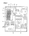
- FIG. 13 depicts an example of helper function that has a bounding box as its input.
- FIG. 14 depicts a second example of a helper function where the user may select a function that has a feature name as its input.
- FIGS. 1-14 of the drawings in which like numerals refer to like features of the invention.
- the present invention takes existing text output from a rule checker in appropriate input format, and automatically displays the text within the design tool using existing design tool capabilities, such as highlighting, zooming, drawing box-regions, and the like.
- Information is graphically associated with the rule checker text output.
- a graphical user interface output of the rule checker is then provided.
- the invention graphically displays the output of the rule checker including the informative text. Any violations are listed in a manner in which they can be individually selected.
- the output is displayed on a unique layer within the design tool so as to make no permanent changes to the original design file. The layers may be safely deleted when no longer in use. This process provides a user with means to annotate and output a subset file for use by other users and designers.
- a designer may then load and view a subset file using the present invention, without having to run the rule checker.
- Useful helper functions are also provided, which allow the user or designer to gain more information about the design. These functions are generally available in the design tool; however, their implementation would normally involve a more intensive manual process.
- the present invention takes the output of the design rule checker and graphically identifies each violation to the user using design tool operations.
- the user selects from a list of violations, which may be presented in a pop-up window, and zooms the view to an appropriate level for the user to clearly see the violation, depending on the type of information contained in the rule checker file. This process highlights and effectively draws a bounding box around any violation in question if applicable.
- the pop-up window is made to contain information identifying the violation along with other pertinent information about it, such as the net name, component name, and the like, which will aid the user in understanding more about the violation.
- the pop-up window also contains information about the checked design rule, which helps the user to understand the violation.
- the output file of the design rule checker must be in a format that can communicate with, and be processed by, the present invention.
- the output file of the design rule checker is the input file for the Invention. The user applies the rule checker text output to speed up and simplify the review of the design rule checker output.
- the present invention generates an output file that allows the user to save information related to identified violations in order to share the information with a designer or other user.
- the user requests that a particular violation be saved.
- the resulting output file contains only those violations that the user requested to be saved.
- a new user reviewing this subset file can then view precisely what the first user experienced.
- the original file is preserved. Consequently, the creation of this subset file is repeatable for multiple, unique output files.
- helper functions are automatically integrated for common activities, such as zooming to a region, measuring cumulative distance between multiple points, resetting visibility, and the like. This integration saves input time and removes input mistakes by reducing the number of keystrokes necessary for input.
- timesavings can be upward of 75-90% of the original, manual review time.
- FIG. 1 depicts the overall process flow for the present invention.
- the invention input file 6 is a software tool that provides a graphical user representation for a printed circuit board design file 1 and the output of a design rule checker 4 .
- the overall application of the invention is typically as follows: The user applies rule checker parameters 3 against a design file or some subset of the design file data 2 within a design rule checker 4 .
- the rule checker 4 compares the design data 1 , 2 against the rule checker parameters 3 and provides output to the user in text form 5 and in a standard file format specified for the input file 6 .
- the present invention then employs a “violation viewer” methodology 8 that generates an output file 9 allowing the user to save information related to identified violations. This includes the data from the design file 1 , and uses the input file 6 to graphically identify the rule checker output to the user.
- a portion of the “violation viewer” methodology 8 is used to create a subset output file 9 that contains only that violation information to be shared with the designer. If appropriate, a text version of this output 7 may also be generated.
- the designer operates the “violation viewer” methodology 8 similar to the original user, applying the subset output file 9 against the design file 1 , using the text output 7 as an additional reference if needed.
- the designer identifies and performs necessary design file changes 10 on the design file 1 . This process may then iterate through from the rule checking process as many times as is deemed necessary by the user.
- the user Upon initializing the software to perform the methodology of the present invention, the user is presented with a pop-up window 11 as shown in FIG. 2 , which lists the violations reported 12 along with some descriptive text 13 taken from the rule checker to identify the rule check performed. If the list 12 is longer than the window permits, a scroll bar 17 is provided to scroll through the list 12 .
- the user may select a violation to be displayed, which will then be highlighted 1) either by selecting it with the mouse pointer, using the “up” and “down” arrow keys on the keyboard, or with the Prev(ious) 18 and Next 19 clickable software buttons.
- useful information such as an identifier number 15 and violation description 16 is shown in the list 12 as provided by the rule checker output 6 .
- the graphical representation of the rule checker output 6 can be shown to the user in a variety of ways.
- the software for the present invention is designed to interact with the design file software using the design file software's various capabilities.
- a feature central to the violation 25 may be highlighted as depicted in FIG. 3 .
- a violation contains a main description 16 and a secondary feature related to the violation 23
- both highlighting of the main feature 25 and highlighting and/or the drawing of a small box around the secondary feature 24 can be performed. This is shown in FIG. 4 .
- a bounding region is pertinent to the violation, a bounding box of prescribed distance may be drawn around the key feature 26 .
- FIG. 5 depicts a bounding box around the region. In this example, a box is drawn around a component pin at a distance from all sides of the pin.
- a bounding box representing the checked region may be drawn 28 , as depicted in FIG. 6 .
- the box is drawn to indicate a feature search region based on a set of grid coordinates specified by the rule checker.
- the box drawn 28 represents one grid box in the overall grid.
- the invention methodology also provides the user with the ability to output a subset list of the violations that need further communication 7 , 9 .
- This output file is created with the “save line” software button 21 on the main pop-up window 11 as shown in FIG. 7 . Once created, the subset output 9 may be viewed graphically within the design tool.
- the helper functions include an initial set “Goto Point”, “Get Distance”, and “Reset Find Filter”, and additional helper functions including “Start Vioviewer”, “Outline ON/OFF”, “Show Comp”, “Show Comp Info”, “Show Decaps”, “Show Pin”, “Show Net”, “Show Net Info”, “Show Seg”, “Get Layer Thick”, “Sublayer Thick”, and “Done”.
- the “Goto Point” allows the user to input an x- and y-coordinate and zooms such that the selected coordinate is at the screen's center.
- the “Get Distance” allows the user to select two points on the screen, returning the distance between the selected two points.
- the “Reset Find Filter” resets the state of the selection feature.
- the “Outline On/Off” toggles the design element called “outline” to an on or off state.
- the “Show Comp” allows the user to input a component identifier, and zooms the display such that the component is at the center of the screen and highlighted.
- the “Show Comp Info” allows the user to input a component identifier, and returns a pop-up window containing the component properties.
- the “Show Decaps” highlights decoupling capacitors connected to the net specified by the user.
- the “Show Pin” takes the user input of a component pin, and zooms so that the pin is in the center of the screen and highlighted.
- Show Net takes the user input of a net, and zooms so that the net is in the center of the screen and highlighted.
- Show Net Info allows the user to input a net identifier, and returns a pop-up window containing the net properties.
- “Show Seg” takes the user input of a net segment, and zooms so that the net segment is in the center of the screen and highlighted.
- “Get Layer Thick” allows the user to select a layer identifier and returns the thickness dimension from the design data.
- “Sublayer Thick” allows the user to select a sublayer identifier and returns the thickness dimension from the design data.
- Done closes the helper window.
- a soft-key button “Start Vioviewer” 31 is programmed to start the viewing of the input files 6 , 9 .
- a violation file selector pop-up window 30 is presented as seen in FIG. 9 .
- This window shows a list of files 33 that may be selected.
- the subset files are created as separate files from the original input files.
- the desired file is identified, it may be selected by clicking on it, which initiates loading it into the file path box 34 .
- the user may type it directly into the file path box 34 . Referring to FIG.
- FIG. 10 depicts the sample violation pop-up window list showing the subset of the overall list specified by a user to communicate with a designer.
- the features 24 , 25 , 26 , 27 shown in FIGS. 2-6 are created as design elements in the design file 1 .
- these design elements 24 , 25 , 26 , 27 are created on a unique layer or class 37 within the design file 1 , and can be deleted from the design file 1 without permanently altering the original data.
- Instructions 35 , 36 for removal of this layer or class 37 may be provided to the user through interaction with the design tool.
- FIG. 11 depicts sample instructions for the CADENCE ALLEGROTM design tool, advising the user of the temporary layer created for viewing violations that can be safely removed without making permanent, destructive changes to the original design.
- FIG. 12 An example of this layer or class 37 within the CADENCE ALLEGRO design environment is shown in FIG. 12 .
- the layer in this example is labeled “VioView” 370 .
- FIG. 8 showed an example of a number of helper functions 29 available via a pop-up window 28 within the invention.
- An example of another helper function 290 is shown in FIG. 13 .
- the user has selected a helper function 290 that has a bounding box as its input.
- a pop-up window 380 enables the user to specify the coordinates of a rectangular box 390 that the invention can draw a bounding box about and zoom in magnification.
- FIG. 12 The layer in this example is labeled “VioView” 370 .
- FIG. 8 showed an example of a number of helper functions 29 available via a pop-up window 28 within the invention.
- An example of another helper function 290 is shown in FIG. 13 .
- the user has selected a helper function 290 that has
- FIG. 14 is a second example of a helper function 290 a where the user may select a function that has a feature name as its input. This selection displays a pop-up box 400 in which the user specifies a feature name 410 . Typical operation of this helper function 290 would highlight the feature and zoom the magnification to an appropriate level.
- the description of the present invention has thus far been based on using the invention to graphically display design rule checker output that is overlaid onto the design file within the design tool environment.
- the invention may be used to output a format that is viewable in a different software program or in a common graphics format such as, but not limited to, JPEG, GIF, TIFF, BMP, HTML, and the like.
- JPEG, GIF, TIFF, BMP, HTML, and the like are examples of the invention as used with the Cadence Allegro design tool.
- the invention is not limited to one tool as long as design tool commands are driven by a software program, the invention can be used in any design tool.
- the subset file or even the original design rule checker file can be translated to work with a design tool other than the one originally used to create the design.
Abstract
Description
Claims (10)
Priority Applications (2)
| Application Number | Priority Date | Filing Date | Title |
|---|---|---|---|
| US10/707,776 US7315990B2 (en) | 2004-01-12 | 2004-01-12 | Method and system for creating, viewing, editing, and sharing output from a design checking system |
| US11/935,865 US7921390B2 (en) | 2004-01-12 | 2007-11-06 | Method and system for creating, viewing, editing, and sharing output from a design checking system |
Applications Claiming Priority (1)
| Application Number | Priority Date | Filing Date | Title |
|---|---|---|---|
| US10/707,776 US7315990B2 (en) | 2004-01-12 | 2004-01-12 | Method and system for creating, viewing, editing, and sharing output from a design checking system |
Related Child Applications (1)
| Application Number | Title | Priority Date | Filing Date |
|---|---|---|---|
| US11/935,865 Continuation US7921390B2 (en) | 2004-01-12 | 2007-11-06 | Method and system for creating, viewing, editing, and sharing output from a design checking system |
Publications (2)
| Publication Number | Publication Date |
|---|---|
| US20050155008A1 US20050155008A1 (en) | 2005-07-14 |
| US7315990B2 true US7315990B2 (en) | 2008-01-01 |
Family
ID=34738974
Family Applications (2)
| Application Number | Title | Priority Date | Filing Date |
|---|---|---|---|
| US10/707,776 Expired - Fee Related US7315990B2 (en) | 2004-01-12 | 2004-01-12 | Method and system for creating, viewing, editing, and sharing output from a design checking system |
| US11/935,865 Expired - Fee Related US7921390B2 (en) | 2004-01-12 | 2007-11-06 | Method and system for creating, viewing, editing, and sharing output from a design checking system |
Family Applications After (1)
| Application Number | Title | Priority Date | Filing Date |
|---|---|---|---|
| US11/935,865 Expired - Fee Related US7921390B2 (en) | 2004-01-12 | 2007-11-06 | Method and system for creating, viewing, editing, and sharing output from a design checking system |
Country Status (1)
| Country | Link |
|---|---|
| US (2) | US7315990B2 (en) |
Cited By (9)
| Publication number | Priority date | Publication date | Assignee | Title |
|---|---|---|---|---|
| US20100287515A1 (en) * | 2009-05-06 | 2010-11-11 | International Business Machines, Corporation | interactive checker in a layout editor |
| US20110107282A1 (en) * | 2009-10-29 | 2011-05-05 | Hong Fu Jin Precision Industry (Shenzhen) Co., Ltd. | Printed circuit board layout system and method thereof |
| CN102385644A (en) * | 2010-08-31 | 2012-03-21 | 英业达股份有限公司 | Drawing method of text tag of circuit board |
| US8166427B1 (en) * | 2007-03-09 | 2012-04-24 | Altera Corporation | Tracing and reporting registers removed during synthesis |
| US8438524B1 (en) | 2009-12-30 | 2013-05-07 | Cadence Design Systems, Inc. | Hierarchical editing of printed circuit board pin assignment |
| US8799836B1 (en) | 2013-07-08 | 2014-08-05 | International Business Machines Corporation | Yield optimization for design library elements at library element level or at product level |
| US10296703B1 (en) * | 2017-09-20 | 2019-05-21 | Cadence Design Systems, Inc. | System and method for visualization in an electronic circuit design |
| US10565342B1 (en) * | 2018-01-30 | 2020-02-18 | Cadence Design Systems, Inc. | Electronic circuit design editor with overlay of layout and schematic design features |
| US10990746B1 (en) * | 2019-10-15 | 2021-04-27 | Taiwan Semiconductor Manufacturing Company Ltd. | Integrated circuit device design method and system |
Families Citing this family (23)
| Publication number | Priority date | Publication date | Assignee | Title |
|---|---|---|---|---|
| TW200539763A (en) * | 2004-05-28 | 2005-12-01 | Hon Hai Prec Ind Co Ltd | Method and system for net-width checking in a layout |
| US20070079266A1 (en) * | 2005-09-30 | 2007-04-05 | Lsi Logic Corporation | Method and computer program for analysis of an integrated circuit design to identify and resolve a problematic structure characterized by multiple rule violations using a design closure knowledge base and a physical design database |
| US7870517B1 (en) | 2006-04-28 | 2011-01-11 | Cadence Design Systems, Inc. | Method and mechanism for implementing extraction for an integrated circuit design |
| US7640527B1 (en) * | 2006-06-29 | 2009-12-29 | Xilinx, Inc. | Method and apparatus for partial reconfiguration circuit design for a programmable device |
| JP4822979B2 (en) * | 2006-08-11 | 2011-11-24 | 株式会社東芝 | Data linkage system, control method thereof, and control program |
| US20080040684A1 (en) * | 2006-08-14 | 2008-02-14 | Richard Crump | Intelligent Pop-Up Window Method and Apparatus |
| US20080229261A1 (en) * | 2007-03-16 | 2008-09-18 | Microsoft Corporation | Design rule system for verifying and enforcing design rules in software |
| US8302078B2 (en) * | 2008-03-10 | 2012-10-30 | The Boeing Company | Lazy evaluation of geometric definitions of objects within procedural programming environments |
| US20100064146A1 (en) * | 2008-09-08 | 2010-03-11 | Integral Wave Technologies, Inc. | Power system design tool |
| US8046726B2 (en) * | 2008-09-16 | 2011-10-25 | Lsi Corporation | Waiver mechanism for physical verification of system designs |
| US8612923B2 (en) * | 2009-02-06 | 2013-12-17 | Cadence Design Systems, Inc. | Methods, systems, and computer-program products for item selection and positioning suitable for high-altitude and context sensitive editing of electrical circuits |
| US8271909B2 (en) * | 2009-02-06 | 2012-09-18 | Cadence Design Systems, Inc. | System and method for aperture based layout data analysis to achieve neighborhood awareness |
| CN101872370B (en) * | 2009-04-21 | 2012-07-18 | 鸿富锦精密工业(深圳)有限公司 | Simulation system and method for design specification of electronic circuit board |
| US8438531B2 (en) * | 2009-12-01 | 2013-05-07 | Cadence Design Systems, Inc. | Visualization and information display for shapes in displayed graphical images |
| US8645901B2 (en) * | 2009-12-01 | 2014-02-04 | Cadence Design Systems, Inc. | Visualization and information display for shapes in displayed graphical images based on a cursor |
| US8533626B2 (en) * | 2009-12-01 | 2013-09-10 | Cadence Design Systems, Inc. | Visualization and information display for shapes in displayed graphical images based on user zone of focus |
| US8407655B2 (en) * | 2010-11-18 | 2013-03-26 | Synopsys, Inc. | Fixing design requirement violations in multiple multi-corner multi-mode scenarios |
| US8555237B1 (en) | 2012-07-05 | 2013-10-08 | Cadence Design Systems, Inc. | Method and apparatus for design rule violation reporting and visualization |
| TW201416686A (en) * | 2012-10-26 | 2014-05-01 | Hon Hai Prec Ind Co Ltd | System and method for searching signals on a hardware circuit diagram |
| CN103970921B (en) * | 2013-02-05 | 2017-09-01 | 中芯国际集成电路制造(上海)有限公司 | A kind of method of automatic sectional drawing when DRC results are examined |
| US10380009B2 (en) | 2015-02-27 | 2019-08-13 | Walmart Apollo, Llc | Code usage map |
| CN105260569A (en) * | 2015-11-09 | 2016-01-20 | 浪潮集团有限公司 | Method of automatically punching ground holes based on CadenceAllegro |
| CN106909670B (en) * | 2017-02-28 | 2020-12-18 | 宇龙计算机通信科技(深圳)有限公司 | Information sharing method and device |
Citations (16)
| Publication number | Priority date | Publication date | Assignee | Title |
|---|---|---|---|---|
| US4873643A (en) | 1987-10-22 | 1989-10-10 | Andrew S. Crawford | Interactive design terminal for custom imprinted articles |
| US5655063A (en) | 1994-06-28 | 1997-08-05 | Computervision Corporation | Topology based tolerancing for geometric modeling operations |
| US5974243A (en) | 1997-10-31 | 1999-10-26 | Hewlett-Packard Company | Adjustable and snap back design-rule halos for computer aided design software |
| US6045584A (en) | 1997-10-31 | 2000-04-04 | Hewlett-Packard Company | Multilevel and beveled-corner design-rule halos for computer aided design software |
| US6055366A (en) * | 1998-02-23 | 2000-04-25 | Advanced Micro Devices, Inc. | Methods and apparatus to perform high voltage electrical rule check of MOS circuit design |
| US6077307A (en) | 1997-10-31 | 2000-06-20 | Hewlett Packard Company | Forced conformance design-rule halos for computer aided design software |
| US6282696B1 (en) | 1997-08-15 | 2001-08-28 | Lsi Logic Corporation | Performing optical proximity correction with the aid of design rule checkers |
| US6370496B1 (en) | 1999-01-04 | 2002-04-09 | Intelect Communications, Inc. | System for intelligent visualization and control of computer hardware |
| US6415421B2 (en) | 2000-06-13 | 2002-07-02 | Mentor Graphics Corporation | Integrated verification and manufacturability tool |
| US6418551B1 (en) * | 2000-08-03 | 2002-07-09 | Avant! Corporation | Design rule checking tools and methods that use waiver layout patterns to waive unwanted dimensional check violations |
| US6453457B1 (en) | 2000-09-29 | 2002-09-17 | Numerical Technologies, Inc. | Selection of evaluation point locations based on proximity effects model amplitudes for correcting proximity effects in a fabrication layout |
| US6539521B1 (en) | 2000-09-29 | 2003-03-25 | Numerical Technologies, Inc. | Dissection of corners in a fabrication layout for correcting proximity effects |
| US6557162B1 (en) | 2000-09-29 | 2003-04-29 | Numerical Technologies, Inc. | Method for high yield reticle formation |
| US6907589B2 (en) * | 2003-02-19 | 2005-06-14 | Hewlett-Packard Development Company, L.P. | System and method for evaluating vias per pad in a package design |
| US7076410B1 (en) * | 1997-01-27 | 2006-07-11 | Unisys Corporation | Method and apparatus for efficiently viewing a number of selected components using a database editor tool |
| US7076749B2 (en) * | 2004-05-28 | 2006-07-11 | International Business Machines Corporation | Method and system for improving integrated circuit manufacturing productivity |
Family Cites Families (1)
| Publication number | Priority date | Publication date | Assignee | Title |
|---|---|---|---|---|
| US7117464B2 (en) * | 2003-02-19 | 2006-10-03 | Hewlett-Packard Development Company, L.P. | System and method for evaluating signal coupling between differential traces in a package design |
-
2004
- 2004-01-12 US US10/707,776 patent/US7315990B2/en not_active Expired - Fee Related
-
2007
- 2007-11-06 US US11/935,865 patent/US7921390B2/en not_active Expired - Fee Related
Patent Citations (16)
| Publication number | Priority date | Publication date | Assignee | Title |
|---|---|---|---|---|
| US4873643A (en) | 1987-10-22 | 1989-10-10 | Andrew S. Crawford | Interactive design terminal for custom imprinted articles |
| US5655063A (en) | 1994-06-28 | 1997-08-05 | Computervision Corporation | Topology based tolerancing for geometric modeling operations |
| US7076410B1 (en) * | 1997-01-27 | 2006-07-11 | Unisys Corporation | Method and apparatus for efficiently viewing a number of selected components using a database editor tool |
| US6282696B1 (en) | 1997-08-15 | 2001-08-28 | Lsi Logic Corporation | Performing optical proximity correction with the aid of design rule checkers |
| US5974243A (en) | 1997-10-31 | 1999-10-26 | Hewlett-Packard Company | Adjustable and snap back design-rule halos for computer aided design software |
| US6045584A (en) | 1997-10-31 | 2000-04-04 | Hewlett-Packard Company | Multilevel and beveled-corner design-rule halos for computer aided design software |
| US6077307A (en) | 1997-10-31 | 2000-06-20 | Hewlett Packard Company | Forced conformance design-rule halos for computer aided design software |
| US6055366A (en) * | 1998-02-23 | 2000-04-25 | Advanced Micro Devices, Inc. | Methods and apparatus to perform high voltage electrical rule check of MOS circuit design |
| US6370496B1 (en) | 1999-01-04 | 2002-04-09 | Intelect Communications, Inc. | System for intelligent visualization and control of computer hardware |
| US6415421B2 (en) | 2000-06-13 | 2002-07-02 | Mentor Graphics Corporation | Integrated verification and manufacturability tool |
| US6418551B1 (en) * | 2000-08-03 | 2002-07-09 | Avant! Corporation | Design rule checking tools and methods that use waiver layout patterns to waive unwanted dimensional check violations |
| US6453457B1 (en) | 2000-09-29 | 2002-09-17 | Numerical Technologies, Inc. | Selection of evaluation point locations based on proximity effects model amplitudes for correcting proximity effects in a fabrication layout |
| US6539521B1 (en) | 2000-09-29 | 2003-03-25 | Numerical Technologies, Inc. | Dissection of corners in a fabrication layout for correcting proximity effects |
| US6557162B1 (en) | 2000-09-29 | 2003-04-29 | Numerical Technologies, Inc. | Method for high yield reticle formation |
| US6907589B2 (en) * | 2003-02-19 | 2005-06-14 | Hewlett-Packard Development Company, L.P. | System and method for evaluating vias per pad in a package design |
| US7076749B2 (en) * | 2004-05-28 | 2006-07-11 | International Business Machines Corporation | Method and system for improving integrated circuit manufacturing productivity |
Cited By (11)
| Publication number | Priority date | Publication date | Assignee | Title |
|---|---|---|---|---|
| US8166427B1 (en) * | 2007-03-09 | 2012-04-24 | Altera Corporation | Tracing and reporting registers removed during synthesis |
| US20100287515A1 (en) * | 2009-05-06 | 2010-11-11 | International Business Machines, Corporation | interactive checker in a layout editor |
| US20110107282A1 (en) * | 2009-10-29 | 2011-05-05 | Hong Fu Jin Precision Industry (Shenzhen) Co., Ltd. | Printed circuit board layout system and method thereof |
| US8201135B2 (en) * | 2009-10-29 | 2012-06-12 | Hong Fu Jin Precision Industry (Shenzhen) Co., Ltd. | Printed circuit board layout system and method thereof |
| US8438524B1 (en) | 2009-12-30 | 2013-05-07 | Cadence Design Systems, Inc. | Hierarchical editing of printed circuit board pin assignment |
| CN102385644A (en) * | 2010-08-31 | 2012-03-21 | 英业达股份有限公司 | Drawing method of text tag of circuit board |
| CN102385644B (en) * | 2010-08-31 | 2013-12-11 | 英业达股份有限公司 | Drawing method of text tag of circuit board |
| US8799836B1 (en) | 2013-07-08 | 2014-08-05 | International Business Machines Corporation | Yield optimization for design library elements at library element level or at product level |
| US10296703B1 (en) * | 2017-09-20 | 2019-05-21 | Cadence Design Systems, Inc. | System and method for visualization in an electronic circuit design |
| US10565342B1 (en) * | 2018-01-30 | 2020-02-18 | Cadence Design Systems, Inc. | Electronic circuit design editor with overlay of layout and schematic design features |
| US10990746B1 (en) * | 2019-10-15 | 2021-04-27 | Taiwan Semiconductor Manufacturing Company Ltd. | Integrated circuit device design method and system |
Also Published As
| Publication number | Publication date |
|---|---|
| US20050155008A1 (en) | 2005-07-14 |
| US7921390B2 (en) | 2011-04-05 |
| US20080066042A1 (en) | 2008-03-13 |
Similar Documents
| Publication | Publication Date | Title |
|---|---|---|
| US7921390B2 (en) | Method and system for creating, viewing, editing, and sharing output from a design checking system | |
| US7990375B2 (en) | Virtual view schematic editor | |
| US8181137B2 (en) | Layout versus schematic error system and method | |
| JP5964062B2 (en) | Image management and presentation | |
| US7584436B2 (en) | Method, system, and program product for controlling a display on a data editing screen | |
| US9552450B2 (en) | Determining a user-specified location in a graphical user interface of an electronic design automation tool | |
| US20100205575A1 (en) | Methods, Systems, and Computer-Program Products for Item Selection and Positioning Suitable for High-Altitude and Context Sensitive Editing of Electrical Circuits | |
| US6230305B1 (en) | Methods and apparatus for configuring schematic diagrams | |
| US9092110B2 (en) | Method and system for implementing a user interface with ghosting | |
| US10078723B1 (en) | Method and apparatus for design rules driven interactive violation display | |
| US7370297B2 (en) | Method, system, and computer program for validating correspondence information between behavior and lower level description of a circuit design | |
| US9304981B1 (en) | System and method for providing an inter-application overlay to communicate information between users and tools in the EDA design flow | |
| JP2008112268A (en) | Timing verification method, timing verification apparatus and timing verification program | |
| US10055533B2 (en) | Visualization of analysis process parameters for layout-based checks | |
| US7076410B1 (en) | Method and apparatus for efficiently viewing a number of selected components using a database editor tool | |
| US20110074812A1 (en) | Method of displaying document with image | |
| KR20080052355A (en) | Cad apparatus, method of editing graphic data, and computer readable recording medium for recording cad program | |
| JP2008310573A (en) | Display method for cad drawing | |
| JP4648194B2 (en) | Printed circuit board design instruction support method and apparatus | |
| US20010032222A1 (en) | System, method and computer accessible storage medium, for creating and editing structured parts list | |
| KR101849648B1 (en) | Process and system for providing an architectural design model | |
| JP2010117963A (en) | Design support method | |
| US20110078649A1 (en) | Wafer layout assisting method and system | |
| US20060076547A1 (en) | Three-dimensional viewing and editing of microcircuit design | |
| CN116629217A (en) | Processing method of process file, electronic equipment and storage medium |
Legal Events
| Date | Code | Title | Description |
|---|---|---|---|
| AS | Assignment |
Owner name: INTERNATIONAL BUSINESS MACHINES CORPORATION, NEW Y Free format text: ASSIGNMENT OF ASSIGNORS INTEREST;ASSIGNORS:ARCHAMBEAULT, BRUCE;CHEN, THADDEUS;COOK, MICHELLE K.;AND OTHERS;REEL/FRAME:014249/0653;SIGNING DATES FROM 20031211 TO 20031218 |
|
| FEPP | Fee payment procedure |
Free format text: PAYOR NUMBER ASSIGNED (ORIGINAL EVENT CODE: ASPN); ENTITY STATUS OF PATENT OWNER: LARGE ENTITY |
|
| STCF | Information on status: patent grant |
Free format text: PATENTED CASE |
|
| FPAY | Fee payment |
Year of fee payment: 4 |
|
| FPAY | Fee payment |
Year of fee payment: 8 |
|
| AS | Assignment |
Owner name: GLOBALFOUNDRIES U.S. 2 LLC, NEW YORK Free format text: ASSIGNMENT OF ASSIGNORS INTEREST;ASSIGNOR:INTERNATIONAL BUSINESS MACHINES CORPORATION;REEL/FRAME:036550/0001 Effective date: 20150629 |
|
| AS | Assignment |
Owner name: GLOBALFOUNDRIES INC., CAYMAN ISLANDS Free format text: ASSIGNMENT OF ASSIGNORS INTEREST;ASSIGNORS:GLOBALFOUNDRIES U.S. 2 LLC;GLOBALFOUNDRIES U.S. INC.;REEL/FRAME:036779/0001 Effective date: 20150910 |
|
| AS | Assignment |
Owner name: WILMINGTON TRUST, NATIONAL ASSOCIATION, DELAWARE Free format text: SECURITY AGREEMENT;ASSIGNOR:GLOBALFOUNDRIES INC.;REEL/FRAME:049490/0001 Effective date: 20181127 |
|
| FEPP | Fee payment procedure |
Free format text: MAINTENANCE FEE REMINDER MAILED (ORIGINAL EVENT CODE: REM.); ENTITY STATUS OF PATENT OWNER: LARGE ENTITY |
|
| LAPS | Lapse for failure to pay maintenance fees |
Free format text: PATENT EXPIRED FOR FAILURE TO PAY MAINTENANCE FEES (ORIGINAL EVENT CODE: EXP.); ENTITY STATUS OF PATENT OWNER: LARGE ENTITY |
|
| STCH | Information on status: patent discontinuation |
Free format text: PATENT EXPIRED DUE TO NONPAYMENT OF MAINTENANCE FEES UNDER 37 CFR 1.362 |
|
| FP | Lapsed due to failure to pay maintenance fee |
Effective date: 20200101 |
|
| AS | Assignment |
Owner name: GLOBALFOUNDRIES INC., CAYMAN ISLANDS Free format text: RELEASE BY SECURED PARTY;ASSIGNOR:WILMINGTON TRUST, NATIONAL ASSOCIATION;REEL/FRAME:054636/0001 Effective date: 20201117 |
|
| AS | Assignment |
Owner name: GLOBALFOUNDRIES U.S. INC., NEW YORK Free format text: RELEASE BY SECURED PARTY;ASSIGNOR:WILMINGTON TRUST, NATIONAL ASSOCIATION;REEL/FRAME:056987/0001 Effective date: 20201117 |