US7314376B2 - Electric distribution box - Google Patents
Electric distribution box Download PDFInfo
- Publication number
- US7314376B2 US7314376B2 US11/393,699 US39369906A US7314376B2 US 7314376 B2 US7314376 B2 US 7314376B2 US 39369906 A US39369906 A US 39369906A US 7314376 B2 US7314376 B2 US 7314376B2
- Authority
- US
- United States
- Prior art keywords
- female
- terminal
- female terminal
- recess
- portions
- Prior art date
- Legal status (The legal status is an assumption and is not a legal conclusion. Google has not performed a legal analysis and makes no representation as to the accuracy of the status listed.)
- Active
Links
Images


Classifications
-
- H—ELECTRICITY
- H01—ELECTRIC ELEMENTS
- H01R—ELECTRICALLY-CONDUCTIVE CONNECTIONS; STRUCTURAL ASSOCIATIONS OF A PLURALITY OF MUTUALLY-INSULATED ELECTRICAL CONNECTING ELEMENTS; COUPLING DEVICES; CURRENT COLLECTORS
- H01R11/00—Individual connecting elements providing two or more spaced connecting locations for conductive members which are, or may be, thereby interconnected, e.g. end pieces for wires or cables supported by the wire or cable and having means for facilitating electrical connection to some other wire, terminal, or conductive member, blocks of binding posts
- H01R11/01—Individual connecting elements providing two or more spaced connecting locations for conductive members which are, or may be, thereby interconnected, e.g. end pieces for wires or cables supported by the wire or cable and having means for facilitating electrical connection to some other wire, terminal, or conductive member, blocks of binding posts characterised by the form or arrangement of the conductive interconnection between the connecting locations
-
- H—ELECTRICITY
- H01—ELECTRIC ELEMENTS
- H01R—ELECTRICALLY-CONDUCTIVE CONNECTIONS; STRUCTURAL ASSOCIATIONS OF A PLURALITY OF MUTUALLY-INSULATED ELECTRICAL CONNECTING ELEMENTS; COUPLING DEVICES; CURRENT COLLECTORS
- H01R13/00—Details of coupling devices of the kinds covered by groups H01R12/70 or H01R24/00 - H01R33/00
- H01R13/02—Contact members
- H01R13/04—Pins or blades for co-operation with sockets
-
- H—ELECTRICITY
- H01—ELECTRIC ELEMENTS
- H01R—ELECTRICALLY-CONDUCTIVE CONNECTIONS; STRUCTURAL ASSOCIATIONS OF A PLURALITY OF MUTUALLY-INSULATED ELECTRICAL CONNECTING ELEMENTS; COUPLING DEVICES; CURRENT COLLECTORS
- H01R13/00—Details of coupling devices of the kinds covered by groups H01R12/70 or H01R24/00 - H01R33/00
- H01R13/02—Contact members
- H01R13/10—Sockets for co-operation with pins or blades
- H01R13/11—Resilient sockets
Definitions
- This invention relates to an electric distribution box in which female-female terminals for electrically and mechanically connecting connection terminals of bus bars, distribution parts, etc., are received and supported in a case or a plate such as a board.
- electric wiring within the equipment is formed by installing strip-like bus bars.
- One example of such equipments is an electric distribution box.
- an electric car, a fuel cell car or the like, a battery, an ignition switch, an inverter, etc,. are provided via this electric distribution box, and an electromagnetic relay is operated based on an output signal from the ignition switch, and main power is transmitted to the inverter while a voltage sensor detects the condition of the battery (see, for example, JP-A-2004-282908 (Page 1, FIG. 1)).
- the electric distribution box comprises a lower case z 1 having distribution part-receiving portions (not shown) respectively receiving distribution parts (such as fuses, an electromagnetic relay and a pressure sensor) and recess portions z 2 , bus bars z 4 each installed on the lower case z 1 and having a connection terminal z 5 received in an upstanding manner within the corresponding recess portion z 2 , female-female terminals z 3 which are completely received within the respective recess portions z 2 , and grip the respective connection terminals z 5 , and an upper case z 6 which is detachably fitted on the lower case z 1 , and has external connection terminal-inserting holes z 7 for the passage of external connection terminals of the distribution parts, etc., therethrough.
- main power is transmitted to the inverter or the like by the ON/OFF operation of the ignition switch.
- the upper case z 6 is fitted on the lower case z 1 having the female-female terminals completely received with the respective recess portions z 2 as described, and therefore the following problems have been encountered.
- the external connection terminal-inserting hole z 7 and the corresponding female-female terminal z 3 are slightly displaced out of registry with each other.
- the side surfaces of the related female-female terminal are flat, and therefore there are occasions when the female-female terminal is inserted in a wrongly-oriented manner into the recess portion.
- the external connection terminal-inserting hole and a holding portion of the corresponding female-female terminal are completely displaced out of registry with each other, so that the external connection terminal, in some cases, has failed to be connected to the female-female terminal.
- FIG. 8 there has been proposed an electric distribution box in which external connection terminal-inserting holes z 10 for the passage of external connection terminals of distribution parts, etc., therethrough are formed in an upper case z 9 , and recess portions z 11 for respectively receiving female-female terminals z 3 are formed on this upper case in surrounding relation respectively to the peripheries of the holes z 10 , thereby preventing a holding portion of the female-female terminal z 3 , received in each recess portion z 11 , from being brought out of registry with the corresponding external connection terminal-inserting hole z 10 .
- an upper surface of a lower case on which a plurality of bus bars are installed is flat, and therefore the shortest distance (that is, the creeping distance measured along an insulating surface) between the two conducting members, that is, each female-to-female terminal z 3 and each of those bus bars (other than the bus bar to which this female-female terminal z 3 is connected) disposed near to this female-female terminal z 3 , becomes smaller as compared with the related structure in which the recess portions are formed on the upper surface of the lower case, and as a result a problem has arises with the insulating performance.
- the invention provides an electric distribution box for containing a distribution parts, comprising:
- a female-female terminal that has holding portions for holding and electrically connecting mating terminals
- a first recess portion is provided on one of the first and second cases, and receives a part of the female-female terminal;
- a second recess portion is provided on the other of the first and second cases, and receives a remaining part of the female-female terminal;
- an inserting hole for inserting one of the mating terminal to contact with the female-female terminal is formed in at least one of the first and second recess portions.
- the female-female terminal has a convex portion formed on a side face thereof.
- An inserting direction-limiting portion is formed on at least one of the first and second recess portions, and is engaged with the convex portion to limit an inserting direction of the female-female terminal.
- the inserting direction-limiting portion is a recess portion that engages with the convex portion of the female-female terminal.
- a projecting portion is formed on either one of the first and second recess portions to guide one of the mating terminals to one of the holding portions of the female-female terminal.
- the female-female terminals includes a frame body having a generally rectangular shape when viewed from the top, and a strip-like resilient piece portion which is provided on the frame body, and is bent downwardly and upwardly so as to form an upper U-shaped portion and a lower U-shaped portion to form the holding portions.
- the first recess portions each for receiving part of the corresponding female-female terminal is formed at the one of the upper case (first case) and the lower case (second case), and the second recess portion for receiving the remainder of the female-female terminal is formed at the other of the upper and lower cases, and the female-female terminal is held by the upper and lower cases. Therefore, there can be provided the electric distribution box in which an external connection terminal-inserting hole, formed at one or both of the first and second recess portions, will not be disposed out of registry with the corresponding female-female terminal, thereby enhancing the connecting reliability of the external connection terminal. And besides, thanks to the provision of the first recess portion for receiving part of the female-female terminal, the creeping distance between the female-female terminal and the nearby bus bars is increased, so that a satisfactory insulating performance can be secured.
- the convex portion, formed on the side surface of the female-female terminal is engaged in the inserting direction-limiting portion formed at the first recess portion and the second recess portion, thereby limiting the inserting direction of the female-female terminal. Therefore, there can be provided the excellent electric distribution box in which the wrong insertion of the female-female terminal into the first and second recess portions is prevented.
- FIG. 1 is a vertical cross-sectional view of an important portion of a preferred embodiment of an electric distribution box A of the present invention.
- FIG. 2 is a view taken along the line X-X of FIG. 1 ;
- FIG. 3 is an exploded, vertical cross-sectional view of the portion of FIG. 1 ;
- FIG. 4 is a perspective view showing an important portion of a lower case of the electric distribution box A of the embodiment
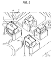
- FIG. 5 is a perspective view showing a condition in which female-female terminals are received in the lower case 2 of FIG. 4 ;
- FIG. 6 is a perspective view showing the appearance of the electric distribution box A of the embodiment.
- FIG. 7 is a vertical cross-sectional view of a related electric distribution box.
- FIG. 8 is a vertical cross-sectional view of another related electric distribution box.
- the electric distribution box of this embodiment is used as an automotive part.
- a battery, an ignition switch, an inverter, etc. are provided via the electric distribution box, and an electromagnetic relay is operated based on an output signal from the ignition switch, and main power is transmitted to the inverter while a voltage sensor detects the condition of the battery, and the functions of the electric distribution box are well known.
- reference numeral 1 denotes female-female terminals
- reference numeral 2 denotes a lower case
- reference numeral 3 denotes bus bars
- reference numeral 4 denotes an upper case.
- the electric distribution box A of this embodiment includes the female-female terminals 1 , the lower case 2 , and the upper case 4 .
- the female-female terminal 1 is formed of an electrically-conductive metallic material. As shown in FIGS. 1 and 2 , the female-female terminal 1 includes a frame body 11 (having a generally rectangular shape when viewed from the top) having an overlapping portion formed at one corner portion thereof. One side wall of the frame body 11 is bent back downwardly at an upper portion of the frame body 11 , and is further is bent back upwardly at a lower portion of the frame body 11 to thereby form a strip-like resilient piece portion 12 having generally U-shaped upper and lower portions.
- the female-female terminal 1 has a pair of holding portions 1 a formed respectively between one of the opposite side walls of the frame body 11 and the resilient piece portion 12 and between the other side wall of the frame body 11 and the resilient piece portion 12 .
- a connection terminal 31 of the bus bar 3 (The bus bars 3 form circuits of the electric distribution box A) is inserted into one of the two holding portions 1 a from the lower side, while a connection terminal 31 ′ of a distribution part or an external equipment is inserted into the other holding portion 1 a from the upper side.
- the frame body 11 has the overlapping portion formed at the one corner portion thereof (that is, at an upper left corner portion in FIG. 2 ), the overlapping portion defining a convex portion 13 .
- Each of the bus bars 3 is formed by blanking a strip-like member from an electrically-conductive metal sheet (such as a copper sheet) by a pressing machine or the like so that a desired wiring pattern can be provided, and then if necessary, a desired portion of the blanked portion is bent to form the connection terminal 31 for connection to the female-female terminal 1 .
- an electrically-conductive metal sheet such as a copper sheet
- the bus bars 3 are installed on the lower case 2 in such a manner that the connection terminals 31 (each formed by bending the end portion of the bus bar 3 upwardly) project upwardly.
- the lower case 2 has first recess portions 21 and distribution part-receiving portions (not shown) formed on an upper surface of the lower case 2 .
- the first recess portions 21 receive the respective female-female terminals 1 each gripping the connection terminal 31
- the distribution part-receiving portions receives the respective distribution parts (such as fuses, an electromagnetic relay and a pressure sensor) forming the electric circuits of the electric distribution box A.
- Engagement portions 24 for engagement with respective retaining portions 43 of the upper case 4 are formed on side surfaces of the lower case 2 .
- each first recess portion 21 has a generally rectangular shape when viewed from the top, and has an open portion 22 for installing the bus bar 3 .
- a projecting portion 25 is formed within the first recess portion 21 , and is disposed close to the open portion 22 .
- the projecting portion 25 supports the female-female terminal 1 in such a manner that the female-female terminal 1 is spaced upwardly from a bus bar installation surface 23 formed on the upper surface of the lower case 2 , and also the projecting portion 25 abuts against the bus bar 3 to thereby guide the connection terminal 31 upwardly.
- the first recess portion 21 (having the generally rectangular shape when viewed from the top) has an inserting direction-limiting portion 26 (into which the convex portion 13 of the female-female terminal 1 is inserted) formed in an inner side surface thereof, and this inserting direction-limiting portion 26 serves to prevent wrong insertion of the female-female terminal 1 into the first recess portion 21
- the first recess portion 21 is formed into such a predetermined depth that a generally upper half portion of the female-female terminal 1 projects outwardly from the first recess portion 21 when the female-female terminal 1 is received in the first recess portion 21 . Also, the inner periphery of the first recess portion 21 has such a predetermined size that the female-female terminal 1 can be inserted and fitted thereinto.
- each female-female terminal 1 is secured to each of the nearby bus bars (that is, those bus bars other than the bus bar to which this female-female terminal 1 is connected), thereby securing a satisfactory insulating performance.
- Second recess portions 41 for respectively receiving the generally upper half portions of the female-female terminals 1 are formed in a lower surface of the upper case 4 .
- External connection terminal-inserting holes 42 for the passage of the downwardly-extending external connection terminals 31 ′ of the distribution parts and external equipments therethrough are formed respectively in predetermined portions of the upper case 4 .
- the retaining portions 43 for engagement with the respective engagement portions 24 of the lower case 2 are formed on side surfaces of the upper case 4 so that the upper case 4 can be detachably engaged with the lower case 2 .
- a second inserting direction-limiting portion 44 is formed within each second recess portion 41 so as to be continuous with the corresponding inserting direction-limiting portion 26 formed at the lower case 2 , and the female-female terminal 1 can be inserted into this limiting portion 44 .
- the distribution parts are received respectively in the distribution part-receiving portions (not shown) of the lower case 2 , and the bus bars 3 are installed on the bus bar installation surface 23 , thereby forming the desired circuits on the lower case 2 .
- the connection terminal 31 of the bus bar 3 is brought into abutting engagement with the projecting portion 25 of the first recess portion 21 , thereby positioning the connection terminal 31 received in a projecting manner within the first recess portion 21 .
- each female-female terminal 1 is inserted the corresponding first recess portion 21 (in which the connection terminal 31 of the bus bar 3 is received in a projecting manner) until the female-female terminal 1 is brought into abutting engagement with the projecting portion 25 .
- the connection terminal 31 of the bus bar 3 is fitted in the holding portion 1 a, and the female-female terminal 1 is received in the first recess portion 21 .
- This received condition is shown in FIG. 5 .
- the upper case 4 is fitted on the lower case 4 in such a manner that the retaining portions 43 of the upper case 4 are engaged respectively with the engagement portions 24 of the lower case 2 .
- the generally upper half portion of the female-female terminal 1 is received in the second recess portion 41 in such a manner that the generally upper half portion of the convex portion 13 of the female-female terminal 1 is engaged in the second inserting direction-limiting portion 44 formed within the second recess portion 41 .
- the external connection terminals 31 ′ of the distribution parts and external equipments are passed respectively through the external connection terminal-inserting holes 42 formed in the upper case 4 , and as a result each of these external connection terminal 31 ′ is inserted into the other holding portion 1 a opposed to the holding portion 1 a in which the connection terminal 31 of the bus bar 3 is fitted. Therefore, the external connection terminals 31 ′ of the distribution parts and external equipments are electrically connected to the respective connection terminals 31 of the bus bars 3 via the respective female-female terminals 1 .
- the first recess portions 21 for respectively receiving the generally lower half portions of the female-female terminals 1 are formed on the lower case 2
- the second recess portions 41 for respectively receiving the generally upper half portions of the female-female terminals 1 are formed at the upper case 4 .
- the female-female terminals 1 are held by the upper case 4 and the lower case 2 , thereby eliminating a fear that the external connection terminal-inserting holes 42 are disposed out of registry with the respective female-female terminals 1 , and at the same time the sufficient creeping distance is secured, thereby positively insulating each female-female terminal 1 from the nearby bus bars.
- the convex portion 13 is formed on the female-female terminal 1 , and the inserting direction-limiting portions 26 and the second inserting direction-limiting portions 44 (in which the convex portions 13 can be engaged) are formed in the lower case 2 and the upper case 4 so as to limit the inserting direction of each female-female terminal 1 , thereby preventing the wrong insertion of the female-female terminal 1 into the first and second recess portions 21 and 41 .
- the convex portion 13 is defined by the overlapping portion formed at the one corner portion of the frame body 11 (that is, the upper left corner portion in FIG. 2 ), the shape and disposition of the convex portion are arbitrary and are not limited in so far as it can limit the inserting direction of the female-female terminal.
Abstract
Description
Claims (6)
Applications Claiming Priority (2)
| Application Number | Priority Date | Filing Date | Title |
|---|---|---|---|
| JPP2005-117654 | 2005-04-15 | ||
| JP2005117654A JP2006296171A (en) | 2005-04-15 | 2005-04-15 | Electric connection box |
Publications (2)
| Publication Number | Publication Date |
|---|---|
| US20060234527A1 US20060234527A1 (en) | 2006-10-19 |
| US7314376B2 true US7314376B2 (en) | 2008-01-01 |
Family
ID=37109088
Family Applications (1)
| Application Number | Title | Priority Date | Filing Date |
|---|---|---|---|
| US11/393,699 Active US7314376B2 (en) | 2005-04-15 | 2006-03-31 | Electric distribution box |
Country Status (2)
| Country | Link |
|---|---|
| US (1) | US7314376B2 (en) |
| JP (1) | JP2006296171A (en) |
Cited By (4)
| Publication number | Priority date | Publication date | Assignee | Title |
|---|---|---|---|---|
| US20080124970A1 (en) * | 2006-06-22 | 2008-05-29 | Omron Corporation | Electronic equipment and method of manufacturing the electronic equipment |
| US20080153325A1 (en) * | 2006-09-08 | 2008-06-26 | Boileau Daniel E | Modular power distribution center |
| US20130003264A1 (en) * | 2011-06-30 | 2013-01-03 | Yazaki Corporation | Electric junction box |
| DE102013106117A1 (en) * | 2013-06-12 | 2014-12-18 | Phoenix Contact Gmbh & Co. Kg | Connector for receiving a flat contact |
Families Citing this family (2)
| Publication number | Priority date | Publication date | Assignee | Title |
|---|---|---|---|---|
| US9444183B2 (en) * | 2014-02-10 | 2016-09-13 | Yazaki North America, Inc. | Bused electrical center for electric or hybrid electric vehicle |
| FR3094578B1 (en) * | 2019-04-01 | 2021-12-10 | Aptiv Tech Ltd | Power connection device for electric heater and connection assembly comprising this device. |
Citations (7)
| Publication number | Priority date | Publication date | Assignee | Title |
|---|---|---|---|---|
| US3548367A (en) * | 1969-05-27 | 1970-12-15 | Amp Inc | Wire splicing unit |
| US5554040A (en) * | 1992-12-10 | 1996-09-10 | Yazaki Corporation | Joint terminal for bus bar |
| US5611713A (en) * | 1994-08-30 | 1997-03-18 | Yazaki Corporation | Wrong insertion prevention structure for a terminal |
| US5755579A (en) * | 1994-12-28 | 1998-05-26 | Yazaki Corporation | Simplified connecting-type electric junction box with wiring harness |
| US20020022387A1 (en) * | 2000-08-09 | 2002-02-21 | Autonetworks Technologies, Ltd. | Electronic control unit mounting structure |
| JP2004282908A (en) | 2003-03-17 | 2004-10-07 | Yazaki Corp | Bus bar connection structure and bus bar connection method of electric junction box |
| US20060105589A1 (en) * | 2004-11-12 | 2006-05-18 | Agc Automotive Americas R&D, Inc | Window pane and a method of bonding a connector to the window pane |
-
2005
- 2005-04-15 JP JP2005117654A patent/JP2006296171A/en not_active Abandoned
-
2006
- 2006-03-31 US US11/393,699 patent/US7314376B2/en active Active
Patent Citations (7)
| Publication number | Priority date | Publication date | Assignee | Title |
|---|---|---|---|---|
| US3548367A (en) * | 1969-05-27 | 1970-12-15 | Amp Inc | Wire splicing unit |
| US5554040A (en) * | 1992-12-10 | 1996-09-10 | Yazaki Corporation | Joint terminal for bus bar |
| US5611713A (en) * | 1994-08-30 | 1997-03-18 | Yazaki Corporation | Wrong insertion prevention structure for a terminal |
| US5755579A (en) * | 1994-12-28 | 1998-05-26 | Yazaki Corporation | Simplified connecting-type electric junction box with wiring harness |
| US20020022387A1 (en) * | 2000-08-09 | 2002-02-21 | Autonetworks Technologies, Ltd. | Electronic control unit mounting structure |
| JP2004282908A (en) | 2003-03-17 | 2004-10-07 | Yazaki Corp | Bus bar connection structure and bus bar connection method of electric junction box |
| US20060105589A1 (en) * | 2004-11-12 | 2006-05-18 | Agc Automotive Americas R&D, Inc | Window pane and a method of bonding a connector to the window pane |
Cited By (6)
| Publication number | Priority date | Publication date | Assignee | Title |
|---|---|---|---|---|
| US20080124970A1 (en) * | 2006-06-22 | 2008-05-29 | Omron Corporation | Electronic equipment and method of manufacturing the electronic equipment |
| US20080153325A1 (en) * | 2006-09-08 | 2008-06-26 | Boileau Daniel E | Modular power distribution center |
| US7591653B2 (en) | 2006-09-08 | 2009-09-22 | Aees, Inc. | Modular power distribution center |
| US20130003264A1 (en) * | 2011-06-30 | 2013-01-03 | Yazaki Corporation | Electric junction box |
| US8804314B2 (en) * | 2011-06-30 | 2014-08-12 | Yazaki Corporation | Electric junction box |
| DE102013106117A1 (en) * | 2013-06-12 | 2014-12-18 | Phoenix Contact Gmbh & Co. Kg | Connector for receiving a flat contact |
Also Published As
| Publication number | Publication date |
|---|---|
| US20060234527A1 (en) | 2006-10-19 |
| JP2006296171A (en) | 2006-10-26 |
Similar Documents
| Publication | Publication Date | Title |
|---|---|---|
| US8961215B2 (en) | Electrical connector assembled component, plug connector, and receptacle connector | |
| US7717720B2 (en) | Electric connection box | |
| JP5224179B2 (en) | Spring force connection device | |
| US7320608B2 (en) | Electric distribution box and method of assembling the same | |
| US7153145B2 (en) | Electric junction box and connection structure of tuning fork terminal | |
| EP2600469B1 (en) | Circuit-terminal connecting device | |
| EP1675220A1 (en) | Electric distribution block and method of assembling the same | |
| EP2889889B1 (en) | Electronic component, connection structure of electronic component and terminal fitting, and electrical connection box having electronic component | |
| EP1596471A1 (en) | Terminal arrangement of electrical apparatus | |
| US7314376B2 (en) | Electric distribution box | |
| US20120119041A1 (en) | Bracket structure in electrical junction box | |
| US7714693B2 (en) | Slow blow fuse and electric junction box | |
| KR101315664B1 (en) | Fuse unit | |
| JP5513952B2 (en) | Holder mounting structure | |
| US9054508B2 (en) | Electrical junction box | |
| JPH08213085A (en) | Lockable flat socket for electric connection | |
| JP5800624B2 (en) | Busbar end structure of electrical junction box | |
| CN109428293B (en) | Electrical junction box | |
| US7291025B2 (en) | Bus bar mounting structure | |
| WO2018147055A1 (en) | Plate-shaped electric conductive member connection structure and plate-shaped electric conduction path | |
| JPH0555456U (en) | Bus bar tab connection terminal | |
| US7021956B2 (en) | Insulation displacement terminal | |
| US20190341716A1 (en) | Joint connector | |
| JP6537100B2 (en) | Multi-stage substrate connection structure and electrical connection box | |
| JP2004350377A (en) | Circuit body and electric joint box for automobile containing the circuit body |
Legal Events
| Date | Code | Title | Description |
|---|---|---|---|
| AS | Assignment |
Owner name: YAZAKI CORPORATION, JAPAN Free format text: ASSIGNMENT OF ASSIGNORS INTEREST;ASSIGNORS:YAGI, SAKAI;ICHIKAWA, YOSHIAKI;MATSUMOTO, SHIGEKI;REEL/FRAME:017868/0569 Effective date: 20060313 |
|
| FEPP | Fee payment procedure |
Free format text: PAYOR NUMBER ASSIGNED (ORIGINAL EVENT CODE: ASPN); ENTITY STATUS OF PATENT OWNER: LARGE ENTITY |
|
| STCF | Information on status: patent grant |
Free format text: PATENTED CASE |
|
| FPAY | Fee payment |
Year of fee payment: 4 |
|
| FPAY | Fee payment |
Year of fee payment: 8 |
|
| MAFP | Maintenance fee payment |
Free format text: PAYMENT OF MAINTENANCE FEE, 12TH YEAR, LARGE ENTITY (ORIGINAL EVENT CODE: M1553); ENTITY STATUS OF PATENT OWNER: LARGE ENTITY Year of fee payment: 12 |
|
| AS | Assignment |
Owner name: YAZAKI CORPORATION, JAPAN Free format text: CHANGE OF ADDRESS;ASSIGNOR:YAZAKI CORPORATION;REEL/FRAME:063845/0802 Effective date: 20230331 |