US7310171B2 - Document surface micro-adjust mechanism - Google Patents
Document surface micro-adjust mechanism Download PDFInfo
- Publication number
- US7310171B2 US7310171B2 US10/063,055 US6305502A US7310171B2 US 7310171 B2 US7310171 B2 US 7310171B2 US 6305502 A US6305502 A US 6305502A US 7310171 B2 US7310171 B2 US 7310171B2
- Authority
- US
- United States
- Prior art keywords
- outer casing
- optical
- carrier chassis
- micro
- adjust
- Prior art date
- Legal status (The legal status is an assumption and is not a legal conclusion. Google has not performed a legal analysis and makes no representation as to the accuracy of the status listed.)
- Active, expires
Links
Images


Classifications
-
- H—ELECTRICITY
- H04—ELECTRIC COMMUNICATION TECHNIQUE
- H04N—PICTORIAL COMMUNICATION, e.g. TELEVISION
- H04N1/00—Scanning, transmission or reproduction of documents or the like, e.g. facsimile transmission; Details thereof
- H04N1/04—Scanning arrangements, i.e. arrangements for the displacement of active reading or reproducing elements relative to the original or reproducing medium, or vice versa
- H04N1/12—Scanning arrangements, i.e. arrangements for the displacement of active reading or reproducing elements relative to the original or reproducing medium, or vice versa using the sheet-feed movement or the medium-advance or the drum-rotation movement as the slow scanning component, e.g. arrangements for the main-scanning
- H04N1/121—Feeding arrangements
- H04N1/1235—Feeding a sheet past a transparent plate; Details thereof
- H04N1/1245—Arrangements for mounting or holding the plate
-
- H—ELECTRICITY
- H04—ELECTRIC COMMUNICATION TECHNIQUE
- H04N—PICTORIAL COMMUNICATION, e.g. TELEVISION
- H04N1/00—Scanning, transmission or reproduction of documents or the like, e.g. facsimile transmission; Details thereof
- H04N1/04—Scanning arrangements, i.e. arrangements for the displacement of active reading or reproducing elements relative to the original or reproducing medium, or vice versa
- H04N1/12—Scanning arrangements, i.e. arrangements for the displacement of active reading or reproducing elements relative to the original or reproducing medium, or vice versa using the sheet-feed movement or the medium-advance or the drum-rotation movement as the slow scanning component, e.g. arrangements for the main-scanning
- H04N1/121—Feeding arrangements
- H04N1/1215—Feeding using one or more cylindrical platens or rollers in the immediate vicinity of the main scanning line
-
- H—ELECTRICITY
- H04—ELECTRIC COMMUNICATION TECHNIQUE
- H04N—PICTORIAL COMMUNICATION, e.g. TELEVISION
- H04N1/00—Scanning, transmission or reproduction of documents or the like, e.g. facsimile transmission; Details thereof
- H04N1/04—Scanning arrangements, i.e. arrangements for the displacement of active reading or reproducing elements relative to the original or reproducing medium, or vice versa
- H04N1/19—Scanning arrangements, i.e. arrangements for the displacement of active reading or reproducing elements relative to the original or reproducing medium, or vice versa using multi-element arrays
- H04N1/191—Scanning arrangements, i.e. arrangements for the displacement of active reading or reproducing elements relative to the original or reproducing medium, or vice versa using multi-element arrays the array comprising a one-dimensional array, or a combination of one-dimensional arrays, or a substantially one-dimensional array, e.g. an array of staggered elements
- H04N1/192—Simultaneously or substantially simultaneously scanning picture elements on one main scanning line
- H04N1/193—Simultaneously or substantially simultaneously scanning picture elements on one main scanning line using electrically scanned linear arrays, e.g. linear CCD arrays
Definitions
- the present invention relates to a document surface micro-adjust mechanism. More particularly, the present invention relates to a micro-adjust mechanism for adjusting the distance of separation between the document surface and the lens of an optical scanner.
- image patterns or documents are often directly captured by a digital camera or indirectly through an optical scanner and converted into digital data files.
- the images in the data files may be identified, edited or stored and later displayed through a computer monitor or other electronic product.
- optical scanners may be classified into palm top scanners, paper feed scanners, drum scanners, and platform scanners.
- the palm top scanner operates by manually moving the scanner over the surface of a scan document horizontally.
- the paper feed scanner operates by putting a scan document at the entrance of a paper feeder.
- the paper feeder moves documents into the scanner one at a time so that scanning is performed at a stable and uniform speed.
- the platform scanner has a flat transparent panel for placing a scan document. An optical system underneath the flat transparent panel moves so that the scan document is scanned one section at a time. Note that since a platform scanner is capable of scanning a B5 size document or bigger, a rather large total trace (TT) is required to project the image of a large document onto a sensor having a smaller width.
- TT total trace
- a scanner of this type is referred to as a card scanner if cards are the main scanning items and a photo scanner if photographs are the main scanning items.
- FIG. 1 is a schematic cross-sectional view of a conventional small document optical scanner.
- the scanner 100 comprises a casing 110 , a transparent document platform 112 , a roller 120 , a light source 130 , a group of reflecting mirrors 140 , an optical lens 150 and a sensor 160 .
- a document 10 driven by the roller 120 is fed onto the document surface 114 of the transparent document platform 112 .
- the document picks up light from the light source 130 and reflects a portion of the light back along an optical path 20 .
- the light reflects repeatedly through the group of reflecting mirrors 140 to enter the optical lens 150 .
- the optical lens 150 focuses and projects the light onto the optical sensor 160 .
- the optical sensor 160 converts the image pattern on the document 10 into digital output signals.
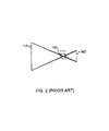
- FIG. 2 is a schematic diagram showing minor adjustment of the optical lens to focus an image on a sensor. Note that the document surface 114 and the sensor 160 (image surface) are fixed relative to each other. Only the optical lens is shifted to bring the light from the document 10 at the document surface 114 exactly in focus on the sensor 160 . The optical lens is fixed in position after adjustment.
- one object of the present invention is to provide a document surface micro-adjust mechanism for an optical scanner.
- this invention provides an optical scanner having a shorter total trace (TT).
- TT total trace
- the document surface on an optical document platform can be micro-adjusted so that distance along the optical path from the document surface to an optical lens within the optical scanner is slightly increased or decreased to bring a document image exactly in focus on an optical sensor.
- the invention provides a document surface micro-adjust mechanism for an optical scanner.
- the optical scanner includes an outer casing, a transparent document platform and an optical lens.
- the transparent document platform is located in the upper portion of the outer casing.
- the transparent document platform has a document surface.
- the optical lens is installed inside the outer casing.
- the document surface micro-adjust mechanism at least includes a carrier chassis having a first side terminal and a second side terminal.
- the first side terminal of the carrier chassis is hinged to an upper sidewall of the outer casing.
- the second side terminal of the carrier chassis has a through hole.
- the transparent document platform is embedded within the carrier chassis.
- the document surface of the transparent document platform can move slightly to adjust the optical path within the scanner.
- the document surface micro-adjust mechanism further includes a locking mechanism mounted on the outer casing.
- the locking mechanism has a locking hole that corresponds in position to the through hole in the carrier chassis.
- the document surface micro-adjust mechanism also includes a locking element that passes through the through hole and engages with the locking hole of the locking mechanism. Depth of the locking element within the locking hole corresponds to the required distance along the optical path from the document surface on the transparent document platform to the optical lens.
- the document surface micro-adjust mechanism also employs at least one elastic element between the carrier chassis and the latching structure. One end of the elastic element pushes against the carrier chassis while the other end of the elastic element pushes against the latching structure. Furthermore, the locking element sequentially passes through the through hole and the elastic element before engaging with the locking hole on the latching structure.
- FIG. 1 is a schematic cross-sectional view of a conventional small document optical scanner
- FIG. 2 is a schematic diagram showing minor adjustment of the optical lens to focus an image on a sensor
- FIG. 3 is a schematic cross-sectional view of a document surface micro-adjust mechanism of an optical scanner according to this invention
- FIG. 4 is a schematic diagram showing minor adjustment of the optical lens to focus an image on a sensor using the document surface micro-adjust mechanism according to this invention.
- FIGS. 5A and 5B are schematic diagrams showing two configurations of the elastic element deployed by the document surface micro-adjust mechanism according to this invention.
- This invention provides a document surface micro-adjust mechanism suitable for manually adjusting the distance from the document surface of an optical lens within the scanner after the scanner is assembled together so that the image is in better focus.
- FIG. 3 is a schematic cross-sectional view of a document surface micro-adjust mechanism on an optical scanner according to this invention.
- the optical scanner 200 (for example, a card scanner or a photo scanner) mainly comprises an outer casing 210 , a transparent document platform 212 , a roller 220 , a light source 230 , a group of reflecting mirrors 240 , an optical lens 250 and a sensor 260 .
- a document 10 is driven by the roller 220 to move onto a document surface 214 within the transparent document platform 212 .
- the document 10 picks up light from the light source 230 and deflects the light along an optical path 20 .
- Each mirror in the mirror group 240 deflects light along the optical path 20 before finally entering the optical lens 250 .
- the optical lens 250 focuses and projects the light onto the optical sensor 260 .
- the optical sensor converts the light pattern obtained from the document 10 into electrical output signals.
- the document surface micro-adjust mechanism 300 comprises of a carrier chassis 310 having a first side terminal 310 a and a second side terminal 310 b .
- the first side terminal 310 a is hinged to an upper sidewall of the outer casing 210 .
- an axial hinge may be used to link up with the upper sidewall of the outer casing 210 .
- the second side terminal 310 b of the carrier chassis 310 has a through hole 312 .
- the transparent document platform 212 is embedded within the carrier chassis 310 . Hence, the document surface 214 within the transparent document platform 212 is able to increase or decrease the optical path slightly by finely adjusting the carrier chassis relative to the scanner 200 .
- the document surface micro-adjust mechanism 300 further includes a latching structure 320 mounted on the outer casing 210 .
- the latching structure 320 is formed, for example, as an integrative unit on the upper wall or sidewall of the outer casing 210 .
- the latching structure 320 has a locking hole 322 that corresponds in position to the through hole 312 on the carrier chassis 310 .
- the document surface micro-adjust mechanism 300 further includes a locking element 330 such as a screw fastener.
- the locking element 330 passes through the through hole 312 and engages with the locking hole 322 . Depth of the locking element 330 inside the locking hole 322 corresponds to the distance of the optical path 20 between the document surface 214 of the transparent document platform 212 and the optical lens 250 .
- the document surface micro-adjust mechanism 300 further includes an elastic element 340 such as a spring or a coiled spring structure.
- the elastic element 340 is inserted between the carrier chassis 310 and the latching structure 320 .
- One end of the elastic element 340 pushes against the carrier chassis 310 while the other end of the elastic element 340 pushes against the latching structure 320 .
- the locking element 330 is a screw and the elastic element 340 is a coiled spring, the locking element 330 passes through the through hole 312 and the elastic element 340 to engage the locking hole 322 in the latching structure 320 .
- the carrier chassis 310 may rotate through a hinge at the first side terminal 310 a .
- the transparent document platform 212 embedded on the carrier chassis 310 also moves when the carrier chassis 310 rotates. Because the carrier chassis 310 translates only a tiny amount (1 ⁇ 2 mm) compared with distance along the optical path 20 , translation perpendicular to the optical path 20 may be neglected. Hence, distance from the document surface 214 to the optical lens 250 may be adjusted by varying the depth of engagement of the locking element 330 inside the locking hole 322 .
- FIG. 4 is a schematic diagram showing minor adjustment of the optical lens to focus an image on a sensor using the document surface micro-adjust mechanism according to this invention.
- distance (object length) from the document surface 214 to the optical lens 250 may be adjusted so that light on the surface of the document 10 is focused clearly on the optical sensor 260 .
- locking glue may be injected into the through hole 312 and around the latching structure 320 , the locking element 330 , and the elastic element 340 , to fix the final adjustment. Once the locking glue is applied, shift in position of the document surface 214 due to transport or vibration is prevented.
- FIGS. 5A and 5B are schematic diagrams showing two configurations of the elastic element deployed by the document surface micro-adjust mechanism according to this invention.
- the elastic element 340 is not a coiled spring (as shown in FIG. 3 ). Since the latching structure 320 is made from plastic material, the elastic element 340 and the latching structure 320 may be formed together as an integrative unit. Similarly, in FIG. 5B , the elastic element 340 and the carrier chassis 310 may be formed together as an integrative unit. Both configurations eliminate the demand for the insertion of a coiled spring.
- the document surface micro-adjust mechanism of this invention utilizes the attachment of a transparent document platform to a carrier chassis that hinges onto an outer casing.
- the document surface of the transparent document platform may shift by a small amount so that the optical distance (object length) between the document surface and the optical lens can be minutely adjusted.
- a positioning glue or material may be applied to the components of the document surface micro-adjust mechanism.
- the document surface micro-adjust mechanism of this invention is applied to an optical scanner. Through the adjustment of total trace distance (object length) between the document surface and the optical lens, magnification of a document may be affected. However, for an optical scanner having a shorter total trace (TT), sensitivity to the adjustment of object length is lower. Consequently, the document surface micro-adjust mechanism of this invention is best suited to an optical scanner having a short total trace, in particular, a portable optical scanner.
- the document surface may deviate from the desired distance to the optical lens.
- the optical distance (object length) between the document surface and the optical lens is adjusted only after the entire assembling process of the optical scanner is complete.
- fixing glue is applied to lock up various components of the document surface micro-adjust mechanism. Hence, the desired position for forming a high-resolution image on the sensor is maintained.
Abstract
Description
Claims (28)
Priority Applications (2)
| Application Number | Priority Date | Filing Date | Title |
|---|---|---|---|
| US10/063,055 US7310171B2 (en) | 2002-03-15 | 2002-03-15 | Document surface micro-adjust mechanism |
| US11/468,784 US7898700B2 (en) | 2002-03-15 | 2006-08-31 | Document surface micro-adjust mechanism |
Applications Claiming Priority (1)
| Application Number | Priority Date | Filing Date | Title |
|---|---|---|---|
| US10/063,055 US7310171B2 (en) | 2002-03-15 | 2002-03-15 | Document surface micro-adjust mechanism |
Related Child Applications (1)
| Application Number | Title | Priority Date | Filing Date |
|---|---|---|---|
| US11/468,784 Continuation US7898700B2 (en) | 2002-03-15 | 2006-08-31 | Document surface micro-adjust mechanism |
Publications (2)
| Publication Number | Publication Date |
|---|---|
| US20030174367A1 US20030174367A1 (en) | 2003-09-18 |
| US7310171B2 true US7310171B2 (en) | 2007-12-18 |
Family
ID=28038677
Family Applications (2)
| Application Number | Title | Priority Date | Filing Date |
|---|---|---|---|
| US10/063,055 Active 2024-11-23 US7310171B2 (en) | 2002-03-15 | 2002-03-15 | Document surface micro-adjust mechanism |
| US11/468,784 Expired - Fee Related US7898700B2 (en) | 2002-03-15 | 2006-08-31 | Document surface micro-adjust mechanism |
Family Applications After (1)
| Application Number | Title | Priority Date | Filing Date |
|---|---|---|---|
| US11/468,784 Expired - Fee Related US7898700B2 (en) | 2002-03-15 | 2006-08-31 | Document surface micro-adjust mechanism |
Country Status (1)
| Country | Link |
|---|---|
| US (2) | US7310171B2 (en) |
Cited By (6)
| Publication number | Priority date | Publication date | Assignee | Title |
|---|---|---|---|---|
| US20040105133A1 (en) * | 2002-10-01 | 2004-06-03 | Canon Kabushiki Kaisha | Image reading apparatus |
| US20070153336A1 (en) * | 2006-01-05 | 2007-07-05 | Avision Inc. | Scanning device having a floating light source |
| US20070165287A1 (en) * | 2001-09-25 | 2007-07-19 | Yin-Chun Huang | Changeable means for different total tracks and its method |
| US20070206239A1 (en) * | 2002-03-15 | 2007-09-06 | Yin-Chun Huang | Document surface micro-adjust mechanism |
| US20080106770A1 (en) * | 2006-11-02 | 2008-05-08 | Avision Inc. | Image reading apparatus and optical module thereof |
| US20090316226A1 (en) * | 2008-06-23 | 2009-12-24 | Nisca Corporation | Image reading apparatus |
Families Citing this family (5)
| Publication number | Priority date | Publication date | Assignee | Title |
|---|---|---|---|---|
| TWI247528B (en) * | 2004-11-18 | 2006-01-11 | Benq Corp | Scanning device |
| TWI296885B (en) * | 2005-06-10 | 2008-05-11 | Reading device applied in scanner | |
| US7835041B2 (en) * | 2005-09-22 | 2010-11-16 | Lexmark International, Inc. | Method and device for reducing a size of a scanning device |
| JP5682213B2 (en) * | 2010-10-06 | 2015-03-11 | セイコーエプソン株式会社 | Image reading apparatus and printer |
| JP6129495B2 (en) * | 2012-08-27 | 2017-05-17 | ゼロックス コーポレイションXerox Corporation | Document reader |
Citations (11)
| Publication number | Priority date | Publication date | Assignee | Title |
|---|---|---|---|---|
| JPS5672459A (en) * | 1979-11-20 | 1981-06-16 | Konishiroku Photo Ind Co Ltd | Position adjusting device for original table glass |
| JPH10285336A (en) * | 1997-04-02 | 1998-10-23 | Ricoh Co Ltd | Original reader for electronic copying machine |
| US5838540A (en) * | 1997-04-09 | 1998-11-17 | Wen-Shyong; Chang | Scanner casing |
| US6012697A (en) * | 1996-04-12 | 2000-01-11 | Nikon Corporation | Stage and supporting mechanism for supporting movable mirror on stage |
| US6055070A (en) * | 1997-02-14 | 2000-04-25 | Samsung Electronics Co., Ltd. | Flat bed scanner apparatus |
| US6075242A (en) * | 1998-11-03 | 2000-06-13 | Mustek Systems Inc. | Optical scanning module with adjustable optical path |
| US6169622B1 (en) * | 1998-11-03 | 2001-01-02 | Mustek Systems Inc. | Optical scanner with a distance adjusting device |
| JP2001235814A (en) * | 2000-02-23 | 2001-08-31 | Nec Eng Ltd | Bending preventive device for document loading glass of large-screen image reader |
| US6376835B1 (en) * | 1999-02-02 | 2002-04-23 | Mustek Systems Inc. | Scanner module with adjustable magnification ratio |
| US6450475B1 (en) * | 2000-12-29 | 2002-09-17 | Mustek Systems Inc. | Platform adjustment device for scanner |
| US6640082B2 (en) * | 2000-11-13 | 2003-10-28 | Nisca Corporation | Image reading apparatus |
Family Cites Families (3)
| Publication number | Priority date | Publication date | Assignee | Title |
|---|---|---|---|---|
| JP5615473B2 (en) * | 2000-01-26 | 2014-10-29 | 三井化学株式会社 | Olefin polymer and process for producing the same |
| US6640083B2 (en) * | 2002-01-15 | 2003-10-28 | Xerox Corporation | Intermediate transparent document holder cover for photocopying machine platen |
| US7310171B2 (en) * | 2002-03-15 | 2007-12-18 | Transpacific Ip, Ltd. | Document surface micro-adjust mechanism |
-
2002
- 2002-03-15 US US10/063,055 patent/US7310171B2/en active Active
-
2006
- 2006-08-31 US US11/468,784 patent/US7898700B2/en not_active Expired - Fee Related
Patent Citations (11)
| Publication number | Priority date | Publication date | Assignee | Title |
|---|---|---|---|---|
| JPS5672459A (en) * | 1979-11-20 | 1981-06-16 | Konishiroku Photo Ind Co Ltd | Position adjusting device for original table glass |
| US6012697A (en) * | 1996-04-12 | 2000-01-11 | Nikon Corporation | Stage and supporting mechanism for supporting movable mirror on stage |
| US6055070A (en) * | 1997-02-14 | 2000-04-25 | Samsung Electronics Co., Ltd. | Flat bed scanner apparatus |
| JPH10285336A (en) * | 1997-04-02 | 1998-10-23 | Ricoh Co Ltd | Original reader for electronic copying machine |
| US5838540A (en) * | 1997-04-09 | 1998-11-17 | Wen-Shyong; Chang | Scanner casing |
| US6075242A (en) * | 1998-11-03 | 2000-06-13 | Mustek Systems Inc. | Optical scanning module with adjustable optical path |
| US6169622B1 (en) * | 1998-11-03 | 2001-01-02 | Mustek Systems Inc. | Optical scanner with a distance adjusting device |
| US6376835B1 (en) * | 1999-02-02 | 2002-04-23 | Mustek Systems Inc. | Scanner module with adjustable magnification ratio |
| JP2001235814A (en) * | 2000-02-23 | 2001-08-31 | Nec Eng Ltd | Bending preventive device for document loading glass of large-screen image reader |
| US6640082B2 (en) * | 2000-11-13 | 2003-10-28 | Nisca Corporation | Image reading apparatus |
| US6450475B1 (en) * | 2000-12-29 | 2002-09-17 | Mustek Systems Inc. | Platform adjustment device for scanner |
Cited By (11)
| Publication number | Priority date | Publication date | Assignee | Title |
|---|---|---|---|---|
| US20070165287A1 (en) * | 2001-09-25 | 2007-07-19 | Yin-Chun Huang | Changeable means for different total tracks and its method |
| US7889398B2 (en) * | 2001-09-25 | 2011-02-15 | Transpacific Systems, Llc | Changeable means for different total tracks and its method |
| US20070206239A1 (en) * | 2002-03-15 | 2007-09-06 | Yin-Chun Huang | Document surface micro-adjust mechanism |
| US7898700B2 (en) * | 2002-03-15 | 2011-03-01 | Yin-Chun Huang | Document surface micro-adjust mechanism |
| US20040105133A1 (en) * | 2002-10-01 | 2004-06-03 | Canon Kabushiki Kaisha | Image reading apparatus |
| US7847983B2 (en) * | 2002-10-01 | 2010-12-07 | Canon Kabushiki Kaisha | Image reading apparatus |
| US20070153336A1 (en) * | 2006-01-05 | 2007-07-05 | Avision Inc. | Scanning device having a floating light source |
| US20080106770A1 (en) * | 2006-11-02 | 2008-05-08 | Avision Inc. | Image reading apparatus and optical module thereof |
| US7733542B2 (en) * | 2006-11-02 | 2010-06-08 | Avision Inc. | Image reading apparatus and optical module thereof |
| US20090316226A1 (en) * | 2008-06-23 | 2009-12-24 | Nisca Corporation | Image reading apparatus |
| US8213062B2 (en) * | 2008-06-23 | 2012-07-03 | Nisca Corporation | Image reading apparatus |
Also Published As
| Publication number | Publication date |
|---|---|
| US20070206239A1 (en) | 2007-09-06 |
| US7898700B2 (en) | 2011-03-01 |
| US20030174367A1 (en) | 2003-09-18 |
Similar Documents
| Publication | Publication Date | Title |
|---|---|---|
| US7898700B2 (en) | Document surface micro-adjust mechanism | |
| US5801851A (en) | Flat bed image scanner | |
| CA2044341C (en) | Compact read/write scanner | |
| US10003712B2 (en) | Illuminating device, image reading apparatus including the illuminating device, and image forming apparatus including the image reading apparatus | |
| JP2007194820A (en) | Image sensor, support member, image sensor unit, and image reading apparatus | |
| US7751100B2 (en) | Method and apparatus for guiding a cable in a scanner | |
| US20220124204A1 (en) | Multi-mode scanning device performing invisible light reflection | |
| US8310735B2 (en) | Image capture module support | |
| US20070279710A1 (en) | Duplex scanning apparatus | |
| US6985267B2 (en) | Dual-carriage scanning apparatus | |
| US6489602B1 (en) | Image scanner having driving mechanism to synchronize movement of transmission-mode light source and image pickup device | |
| US6304358B1 (en) | Reflective/transmissive scanner with synchronously moving image sensor and light source | |
| US6243185B1 (en) | Reflective/transmissive scanner with removable scanning platform and docking port | |
| US20080084588A1 (en) | Optical device with movable optical module | |
| JP2002333749A (en) | Image forming device | |
| US20110157656A1 (en) | Scanner with real-time calibration | |
| US6008501A (en) | Apparatus and method for automatically detecting presence of a scanned document | |
| US7439490B2 (en) | Reading-line adjusting device of image scanner | |
| US8194295B2 (en) | Duplex scanning apparatus | |
| US6031640A (en) | Scanner driving apparatus | |
| US6545266B2 (en) | Four-direction adjustable optical module | |
| CN1527241A (en) | Scanning instrument | |
| US20040026602A1 (en) | Adjustable light converging device | |
| US7359096B2 (en) | Floating window | |
| JPH08298573A (en) | Image reader |
Legal Events
| Date | Code | Title | Description |
|---|---|---|---|
| AS | Assignment |
Owner name: UMAX DATA SYSTEMS, INC., TAIWAN Free format text: ASSIGNMENT OF ASSIGNORS INTEREST;ASSIGNORS:HUANG, YIN-CHUN;CHIANG, SHU-YA;REEL/FRAME:012777/0485 Effective date: 20020124 |
|
| AS | Assignment |
Owner name: VEUTRON CORPORATION, TAIWAN Free format text: CHANGE OF NAME;ASSIGNOR:UMAX DATA SYSTEMS INC.;REEL/FRAME:016800/0203 Effective date: 20021029 |
|
| AS | Assignment |
Owner name: TRANSPACIFIC IP, LTD.,TAIWAN Free format text: ASSIGNMENT OF ASSIGNORS INTEREST;ASSIGNOR:VEUTRON CORPORATION;REEL/FRAME:017564/0747 Effective date: 20050706 Owner name: TRANSPACIFIC IP, LTD., TAIWAN Free format text: ASSIGNMENT OF ASSIGNORS INTEREST;ASSIGNOR:VEUTRON CORPORATION;REEL/FRAME:017564/0747 Effective date: 20050706 |
|
| STCF | Information on status: patent grant |
Free format text: PATENTED CASE |
|
| AS | Assignment |
Owner name: TRANSPACIFIC SYSTEMS, LLC, DELAWARE Free format text: ASSIGNMENT OF ASSIGNORS INTEREST;ASSIGNOR:TRANSPACIFIC IP LTD.;REEL/FRAME:023107/0267 Effective date: 20090618 Owner name: TRANSPACIFIC SYSTEMS, LLC,DELAWARE Free format text: ASSIGNMENT OF ASSIGNORS INTEREST;ASSIGNOR:TRANSPACIFIC IP LTD.;REEL/FRAME:023107/0267 Effective date: 20090618 |
|
| CC | Certificate of correction | ||
| FPAY | Fee payment |
Year of fee payment: 4 |
|
| AS | Assignment |
Owner name: TITUSVILLE CANAVERAL LLC, DELAWARE Free format text: MERGER;ASSIGNOR:TRANSPACIFIC SYSTEMS, LLC;REEL/FRAME:030628/0681 Effective date: 20130213 |
|
| AS | Assignment |
Owner name: INTELLECTUAL VENTURES I LLC, DELAWARE Free format text: MERGER;ASSIGNOR:TITUSVILLE CANAVERAL LLC;REEL/FRAME:030639/0330 Effective date: 20130214 |
|
| FPAY | Fee payment |
Year of fee payment: 8 |
|
| MAFP | Maintenance fee payment |
Free format text: PAYMENT OF MAINTENANCE FEE, 12TH YEAR, LARGE ENTITY (ORIGINAL EVENT CODE: M1553); ENTITY STATUS OF PATENT OWNER: LARGE ENTITY Year of fee payment: 12 |