US7304339B2 - Passivation structure for ferroelectric thin-film devices - Google Patents
Passivation structure for ferroelectric thin-film devices Download PDFInfo
- Publication number
- US7304339B2 US7304339B2 US11/470,950 US47095006A US7304339B2 US 7304339 B2 US7304339 B2 US 7304339B2 US 47095006 A US47095006 A US 47095006A US 7304339 B2 US7304339 B2 US 7304339B2
- Authority
- US
- United States
- Prior art keywords
- electrode
- passivation layer
- layer
- capacitor
- opening
- Prior art date
- Legal status (The legal status is an assumption and is not a legal conclusion. Google has not performed a legal analysis and makes no representation as to the accuracy of the status listed.)
- Active
Links
Images


Classifications
-
- H—ELECTRICITY
- H01—ELECTRIC ELEMENTS
- H01L—SEMICONDUCTOR DEVICES NOT COVERED BY CLASS H10
- H01L27/00—Devices consisting of a plurality of semiconductor or other solid-state components formed in or on a common substrate
- H01L27/02—Devices consisting of a plurality of semiconductor or other solid-state components formed in or on a common substrate including semiconductor components specially adapted for rectifying, oscillating, amplifying or switching and having at least one potential-jump barrier or surface barrier; including integrated passive circuit elements with at least one potential-jump barrier or surface barrier
- H01L27/04—Devices consisting of a plurality of semiconductor or other solid-state components formed in or on a common substrate including semiconductor components specially adapted for rectifying, oscillating, amplifying or switching and having at least one potential-jump barrier or surface barrier; including integrated passive circuit elements with at least one potential-jump barrier or surface barrier the substrate being a semiconductor body
- H01L27/10—Devices consisting of a plurality of semiconductor or other solid-state components formed in or on a common substrate including semiconductor components specially adapted for rectifying, oscillating, amplifying or switching and having at least one potential-jump barrier or surface barrier; including integrated passive circuit elements with at least one potential-jump barrier or surface barrier the substrate being a semiconductor body including a plurality of individual components in a repetitive configuration
- H01L27/105—Devices consisting of a plurality of semiconductor or other solid-state components formed in or on a common substrate including semiconductor components specially adapted for rectifying, oscillating, amplifying or switching and having at least one potential-jump barrier or surface barrier; including integrated passive circuit elements with at least one potential-jump barrier or surface barrier the substrate being a semiconductor body including a plurality of individual components in a repetitive configuration including field-effect components
-
- H—ELECTRICITY
- H01—ELECTRIC ELEMENTS
- H01L—SEMICONDUCTOR DEVICES NOT COVERED BY CLASS H10
- H01L28/00—Passive two-terminal components without a potential-jump or surface barrier for integrated circuits; Details thereof; Multistep manufacturing processes therefor
- H01L28/40—Capacitors
- H01L28/55—Capacitors with a dielectric comprising a perovskite structure material
- H01L28/57—Capacitors with a dielectric comprising a perovskite structure material comprising a barrier layer to prevent diffusion of hydrogen or oxygen
-
- H—ELECTRICITY
- H10—SEMICONDUCTOR DEVICES; ELECTRIC SOLID-STATE DEVICES NOT OTHERWISE PROVIDED FOR
- H10B—ELECTRONIC MEMORY DEVICES
- H10B12/00—Dynamic random access memory [DRAM] devices
-
- H—ELECTRICITY
- H01—ELECTRIC ELEMENTS
- H01L—SEMICONDUCTOR DEVICES NOT COVERED BY CLASS H10
- H01L28/00—Passive two-terminal components without a potential-jump or surface barrier for integrated circuits; Details thereof; Multistep manufacturing processes therefor
- H01L28/40—Capacitors
- H01L28/60—Electrodes
- H01L28/65—Electrodes comprising a noble metal or a noble metal oxide, e.g. platinum (Pt), ruthenium (Ru), ruthenium dioxide (RuO2), iridium (Ir), iridium dioxide (IrO2)
Definitions
- passivation layer materials are usually chosen based on process availability, compatibility with previous processing, and desired characteristics. In particular, materials that can be utilized in other parts of the design are preferable to reduce design complexity and to minimize manufacturing costs.
- Typical examples of passivation layer materials include silicon nitride (Si 3 N 4 ), silicon dioxide (SiO 2 ), and aluminum oxide (Al 2 O 3 ).
- Si 3 N 4 is desirable for its ability to define small critical dimensions, but its thickness may be limited due to stress effects. In contrast, SiO 2 may be used for thicker layers with fewer stress effects.
- passivation layers used in fabrication processes are intended to have little or no effect on the behavior and characteristics of underlying devices.
- the interface between the passivation layer and other active layers may produce paths for leakage currents to flow. These paths, also called “leakage paths,” are undesirable for power efficiency and reliability.
- the tunable BST capacitor 105 includes a bottom electrode 115 , which may be a conducting layer such as a metal, formed on a substrate 120 .
- a ferroelectric BST thin film dielectric layer 125 is sandwiched between the bottom electrode 115 and a top electrode 130 , which may be another metal layer.
- An additional conductive layer 135 may be provided to form a low resistance contact to the top electrode 130 .
- a first passivation layer 140 protects the bottom electrode 115 , the dielectric layer 125 , and the top electrode 130 . Because of the high dielectric constant of BST, the top electrode 130 is sometimes small in physical dimension, requiring the first passivation layer 140 to have excellent step coverage and to be capable of patterning small critical dimensions. For semiconductor processes, Si 3 N 4 is often used, although SiO 2 and Al 2 O 3 may also be used.
- a second passivation layer 145 protects the entire structure, and includes openings 150 to allow electrical contact to the BST capacitor 105 .
- the fixed capacitor 110 includes a bottom electrode 155 , which may be formed using the same conducting layer as the bottom electrode 115 of the BST capacitor 105 .
- the passivation layer 140 serves as the dielectric layer for the fixed capacitor 110
- the conductive layer 135 serves as the top electrode for the fixed capacitor 110 .
- a ferroelectric thin film device has a first electrode integrated on a substrate, a ferroelectric thin film layer contacting the first electrode, and a second electrode contacting the ferroelectric thin film layer.
- a first passivation layer overlies the first electrode, the ferroelectric thin film layer, and the second electrode, and includes an opening exposing a portion of the ferroelectric thin film layer along a path that extends along a surface of the ferroelectric thin film layer between the first electrode and the second electrode.
- a second passivation layer contacts the ferroelectric thin film layer through the opening. In a particular design embodiment, the opening also exposes a portion of the second electrode, and the second passivation layer also contacts the second electrode.
- a ferroelectric parallel plate capacitor may be fabricated by forming a bottom electrode supported by a substrate.
- a ferroelectric thin film dielectric layer is formed over the bottom electrode.
- a top electrode is formed over the dielectric layer.
- a first passivation layer is formed overlying the bottom electrode, the dielectric layer, and the top electrode.
- An opening in the first passivation layer exposes a portion of the dielectric layer along a path that extends along a surface of the dielectric layer between the top electrode and the bottom electrode.
- a second passivation layer is formed overlying the first passivation layer and contacts the dielectric layer through the opening. In a particular design embodiment, the second passivation layer also contacts the bottom electrode through the opening.
- a ferroelectric thin film resistor has a first electrode integrated on a substrate, a ferroelectric thin film layer contacting the first electrode, and a second electrode contacting the ferroelectric thin film layer.
- a first passivation layer overlies the first electrode, the ferroelectric thin film layer, and the second electrode.
- a current flow through the resistor flows at an interface between the ferroelectric thin film layer and the first passivation layer.
- the first passivation layer includes an opening exposing a portion of the ferroelectric thin film layer along a path between the electrodes along the interface between the ferroelectric thin film layer and the first passivation layer, and a second passivation layer overlying the first passivation layer contacts the ferroelectric thin film layer through the opening.
- one or both electrodes may be platinum
- the first passivation layer may be silicon nitride
- the second passivation layer may be polyimide
- the ferroelectric thin film layer may be barium titanate, strontium titanate, or a composite of the two.
- FIG. 2 is a cross-sectional view of one embodiment of a BST capacitor including a passivation structure in accordance with the present invention.
- FIGS. 3A and 3B are enlarged cross-sectional views of the BST capacitor of FIG. 1 and the BST capacitor of FIG. 2 , respectively.
- FIG. 5 is a cross-sectional view of a BST capacitor including a passivation structure in accordance with another embodiment of the present invention.
- FIG. 7 is a cross-sectional view of a BST capacitor including a passivation structure in accordance with another embodiment of the present invention.
- FIGS. 8A-8H are top view and cross-sectional view pairs, illustrating another exemplary fabrication process for BST parallel plate capacitors in accordance with the present invention.
- FIG. 9B is one embodiment of a circuit diagram modeling the BST capacitor of FIG. 9A .
- FIG. 11A is a cross-sectional view of a conventional BST gap capacitor fabricated using semiconductor process technology including a conventional passivation scheme.
- FIG. 11B is a cross-sectional view of a BST gap capacitor including a passivation structure in accordance with one embodiment of the present invention.
- Embodiments of passivation structures, including methods of fabrication, for ferroelectric thin film devices, such as BST capacitors, are described herein.
- the passivation structures and their methods of fabrication advantageously require minimal change to existing fabrication processes.
- FIG. 2 is a cross-sectional view of a BST capacitor 200 including a passivation structure in accordance with one embodiment of the present invention.
- the BST capacitor 200 is integrated on a substrate 120 and includes a bottom electrode 115 , a top electrode 130 , and a BST thin film dielectric layer 125 sandwiched between the top electrode 130 and the bottom electrode 115 .
- the active region of the capacitor is defined by the overlap between the top electrode 130 , the dielectric layer 125 , and the bottom electrode 115 .
- An additional conductive layer 135 is provided to form a low resistance contact to the top electrode 130 .
- FIG. 1 is provided to form a low resistance contact to the top electrode 130 .
- a first passivation layer 140 for example, Si 3 N 4 , protects the bottom electrode 115 , the dielectric layer 125 , and the top electrode 130 , while a second passivation layer 145 protects the entire structure and includes openings 150 to allow electrical contact to the BST capacitor 200 .
- the passivation layer 140 of the BST capacitor 200 also includes an opening 205 to interrupt the leakage path that can form between the top electrode 130 and the bottom electrode 115 at the interface of the dielectric layer 125 and the passivation layer 140 .
- FIGS. 3A and 3B are enlarged cross-sectional views of the BST capacitor 105 of FIG. 1 and the BST capacitor 200 of FIG. 2 , respectively, illustrating the function of the opening 205 in the passivation layer 140 .
- the leakage path 160 that exists in the conventional BST capacitor 105 of FIG. 3A is broken by the opening 205 in the passivation layer 140 in the BST capacitor 200 of FIG. 3B .
- FIG. 4 compares leakage current versus voltage characteristics of conventional BST devices and BST devices fabricated with ring passivation structures in accordance with the present invention. All devices measured were 15 ⁇ m by 15 ⁇ m BST capacitors from the same wafer. Standard, i.e., conventional, BST devices, such as the BST capacitor 105 of FIG. 1 , are indicated by diamonds. BST devices in accordance with the present invention, such as the BST capacitor 200 of FIG. 2 , are indicated by squares and labeled “N1 13 Ring,” and include openings shaped as rings surrounding the capacitors in the first passivation layer (N 1 ). FIG. 4 indicates the leakage current for BST capacitors fabricated with a passivation structure in accordance with one embodiment of the present invention were significantly lower than the leakage current of standard BST capacitors.
- FIG. 5 is a cross-sectional view of a BST capacitor 500 including a passivation structure in accordance with another embodiment of the present invention.
- the BST capacitor 500 is similar to the BST capacitor 200 of FIG. 2 and includes a substrate 120 , a bottom electrode 115 , a top electrode 130 , and a BST thin film dielectric layer 125 sandwiched between the top electrode 130 and the bottom electrode 115 .
- a conductive layer 135 forms a low resistance contact to the top electrode 130 .
- a first passivation layer 140 for example, Si 3 N 4 , protects the bottom electrode 115 , the dielectric layer 125 , and the top electrode 130 .
- a second passivation layer 145 protects the entire BST capacitor 500 and includes openings 150 to allow electrical contact to the BST capacitor 500 with a conductive layer 555 .
- a third passivation layer 560 overlies the entire structure.
- the passivation layer 140 of the BST capacitor 500 also includes an opening 505 to interrupt the leakage path that can form between the top electrode 130 and the bottom electrode 115 at the interface of the dielectric layer 125 and the passivation layer 140 .
- the opening 505 is larger, however, than the opening 205 of FIG. 2 and also exposes a portion of the bottom electrode 115 .
- the openings 205 and 505 are merely illustrative of various configurations that may be possible for the passivation structure of the current invention.
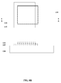
- FIGS. 6A-6H are top view and cross-sectional view pairs, illustrating an exemplary fabrication process for BST parallel plate capacitors in accordance with the present invention.
- Each individual figure shows a different phase of fabrication, while the sequence of figures shows the overall fabrication process.
- Each figure shows both a top view and a corresponding cross-sectional view, through the line A-A, of the capacitor during fabrication.
- the fabricated capacitor is shown in the last figure of the sequence.
- the layer currently being processed is shown in a heavy weight line, except for the last figure of the sequence, which shows the first passivation layer in a heavy weight line.
- FIGS. 6A-6H illustrates fabrication of the BST capacitor 500 of FIG. 5
- the process may also be used to fabricate other BST capacitors, such as the BST capacitor 200 of FIG. 2 .
- a substrate 120 including a sandwich structure of layers comprising a bottom electrode 115 , a BST thin film dielectric layer 125 , and a top electrode 130 .
- temperature resistant, inexpensive, insulating substrates 120 are usually preferred, including but not limited to high-resistivity silicon (HR Si), crystalline sapphire (Al 2 O 3 ), aluminum nitride (AlN), quartz, and glass. These substrates are preferably polished for low surface roughness for compatibility with growth of smooth ferroelectric films with high breakdown fields.
- the bottom electrode 115 is a thin layer of platinum, which may be deposited on the substrate 120 by sputtering or evaporation. Platinum is selected for compatibility with the BST thin film processing. A thin layer for the bottom electrode 115 is preferred to minimize roughness during subsequent processing.
- the top electrode 130 may also be a thin layer of platinum, formed over the BST thin film dielectric layer 125 .
- BST barium titanate
- strontium titanate for convenience, the term “BST” is used throughout to refer to all of these materials even though, strictly speaking, barium titanate does not contain strontium and strontium titanate does not contain barium.
- barium titanate”, “strontium titanate”, and “barium strontium titanate” shall be used to refer to the specific materials. This is strictly for convenience, to avoid having to repeat the phrase “barium titanate, strontium titanate and/or barium strontium titanate” throughout.
- the BST materials can also include small concentrations of one or more dopants to modify certain properties.
- the BST thin film dielectric layer 125 may be grown or deposited over the layer for the bottom electrode 115 .
- the BST thin film dielectric layer 125 is then etched using standard etch techniques.
- the dielectric layer 125 may be wet etched or dry etched, for example, by ion milling.
- a patterned photoresist layer may act as an etch mask.
- a passivation structure is formed.
- the material for the first passivation layer 140 is silicon nitride, Si 3 N 4 , which is deposited over the structure and etched using standard photolithography and etch techniques, such as reactive ion etching.
- the Si 3 N 4 layer is patterned to form a center opening to provide access to the top electrode 130 .
- the Si 3 N 4 layer is also patterned to form an opening 505 to break the leakage path that forms between the top electrode 130 and the bottom electrode 115 at the interface of the dielectric layer 125 and the passivation layer 140 . As shown in the top view of FIG.
- the conductive layer 135 is formed to contact the top electrode 130 and the bottom electrode 115 .
- the conductive layer may be, for example, gold, which provides a low resistance electrical contact to the electrodes 115 , 130 . It is advantageous to place the conductive layer 135 in close proximity to the active region of the BST capacitor to reduce the overall resistance resulting from the platinum electrodes 115 , 130 .
- the gold may be patterned, for example, using a lift off process, in which a photoresist layer is first deposited and patterned using standard photolithography techniques. The gold is then deposited over the photoresist, possibly after deposition of an adhesion layer. Removing the photoresist layer leaves the patterned conductive layer 135 .
- the gold may be deposited before the patterned photoresist layer and then wet etched using an iodine-based gold etchant that attacks gold but not BST or platinum.
- the second passivation layer 145 is then deposited and dry etched.
- the second passivation layer 145 may be, for example, a polyimide.
- the passivation layer 145 passivates regions of the BST thin film dielectric layer 125 and the bottom electrode 115 exposed in the opening 505 .
- the conductive layer 555 is then formed to produce metal wiring to provide contact to the BST capacitor.
- the conductive layer 555 is gold, which may be deposited on the surface by electroplating. If necessary, the gold may be patterned using standard photolithography and etch techniques, for example, a wet etch.
- the third passivation layer 560 is deposited over the entire structure to protect the BST capacitor 500 .
- the third passivation layer 560 may be, for example bisbenzocyclobutene (BCB).
- BCB bisbenzocyclobutene
- standard annealing techniques typically are used to improve the quality of the BST materials, for example, by repairing damage that may have occurred during the BST processing steps. Annealing can also improve the quality of the interfaces between the BST thin film dielectric layer 125 and the electrodes 115 , 130 .
- This lateral configuration of the dielectric layer 125 prevents the passivation layer 140 from contacting the bottom electrode 115 along the edge 765 of the bottom electrode 115 . This prevents formation of the leakage path between the top electrode 130 and the bottom electrode 115 along the edge 765 of the bottom electrode 115 .
- an opening 705 in the embodiment of FIG. 7 has a different lateral configuration than the opening 505 of FIG. 5 .
- the opening 705 is located primarily in areas where leaving the passivation layer 140 would otherwise create the leakage path between the top electrode 130 and the bottom electrode 115 along the interface of the BST thin film dielectric layer 125 . As shown in FIG. 7 , the opening 705 is located where conductive layer 135 contacts bottom electrode 115 , so that the edge of the BST thin film dielectric layer 125 is exposed to the second passivation layer 145 and to the conductive layer 135 .
- FIGS. 8A-8H are top view and cross-sectional view pairs, illustrating another exemplary fabrication process for BST parallel plate capacitors in accordance with the present invention.
- each individual figure shows a different phase of fabrication, while the sequence of figures shows the overall fabrication process.
- Each figure shows both a top view and a corresponding cross-sectional view, through the line A-A, of the capacitor during fabrication.
- the fabricated capacitor is shown in the last figure of the sequence.
- the layer currently being processed is shown in a heavy weight line, except for the last figure of the sequence, which shows the first passivation layer in a heavy weight line.
- FIGS. 8A-8H illustrates fabrication of the BST capacitor 700 of FIG. 7
- the process may also be used to fabricate other BST capacitors, such as the BST capacitor 500 of FIG. 5 .
- the process begins with a substrate 120 , which may be, for example, high-resistivity silicon (HR Si), crystalline sapphire (Al 2 O 3 ), aluminum nitride (AlN), quartz, glass, or another substrate. These substrates are preferably polished for low surface roughness for compatibility with growth of smooth ferroelectric films with high breakdown fields.
- the bottom electrode 115 is formed on the substrate 120 using, for example, a lift off process in which a layer of photoresist is deposited on the substrate 120 and patterned using standard photolithography techniques.
- the bottom electrode 115 is a thin layer of platinum, which may be deposited over the photoresist lift off mask on the substrate 120 by sputtering or evaporation.
- a thin layer is preferred to minimize roughness during subsequent processing, while platinum provides compatibility with subsequent BST processing. Removal of the photoresist mask leaves the patterned bottom electrode 115 on the substrate 120 .
- the thin layer of platinum can be deposited on the substrate 120 and subsequently patterned into the bottom electrode 115 using standard photolithography and etch techniques.
- the BST thin film dielectric layer 125 is deposited over the bottom electrode 115 and etched using standard etch techniques. Specifically, a photoresist layer may be deposited and patterned using standard photolithography techniques to act as a wet etch mask. As discussed previously, the term “BST” refers to thin film dielectrics, for example, those composed of barium titanate, strontium titanate, and composites of the two, which may also include small concentrations of one or more dopants to modify certain properties.
- the top electrode 130 is formed overlying the BST thin film dielectric layer 125 and the bottom electrode 115 .
- the top electrode 130 may also be a thin layer of platinum.
- the top electrode 130 may be formed, for example using a lift off process, in which a layer of photoresist is deposited and patterned to act as a lift off mask. A conductive layer is then deposited over the lift off mask, for example, by evaporation or sputtering. Removal of the photoresist lift off mask leaves the patterned top electrode 130 .
- the top electrode 130 may be formed using standard photolithography and etch techniques in which the conductive material is deposited prior to the patterned photoresist and selected portions of the conductive layer are etched away to form the lateral shape of the top electrode 130 .
- the material for the first passivation layer 140 is silicon nitride, Si 3 N 4 , which is deposited over the structure and etched using standard photolithography and etch techniques, such as reactive ion etching.
- the Si 3 N 4 layer is patterned to form a center opening to provide access to the top electrode 130 .
- the Si 3 N 4 layer is also patterned to form an opening 705 to break the leakage path that forms between the top electrode 130 and the bottom electrode 115 at the interface of the dielectric layer 125 and the passivation layer 140 . As shown in the top view of FIG.
- the opening 705 includes three sides of a rectangular ring around the active region of the BST capacitor, i.e., the shape of a squared-off U.
- the opening may form a complete ring or take the shape of a different polygon.
- the conductive layer 135 is formed to contact the top electrode 130 and the bottom electrode 115 .
- the conductive layer may be, for example, gold, which provides a low resistance electrical contact to the electrodes 115 , 130 . It is advantageous to place the conductive layer 135 in close proximity to the active region of the BST capacitor to reduce the overall resistance resulting from the platinum electrodes 115 , 130 .
- the gold may be etched, for example, using a lift off process, in which a photoresist layer is first deposited and patterned using standard photolithography techniques. The gold is then deposited over the photoresist, possibly after deposition of an adhesion layer. Removing the photoresist layer leaves the patterned conductive layer 135 .
- the gold may be deposited before the patterned photoresist layer and then wet etched using an iodine-based gold etchant that attacks gold but not BST or platinum.
- the second passivation layer 145 is then deposited and dry etched.
- the second passivation layer 145 may be, for example, a polyimide.
- the passivation layer 145 passivates regions of the BST thin film dielectric layer 125 and the bottom electrode 115 exposed in the opening 705 .
- the conductive layer 555 is then formed to produce metal wiring to provide contact to the BST capacitor.
- the conductive layer 555 is gold, which may be deposited on the surface by electroplating. If necessary, the gold may be patterned using standard photolithography and etch techniques, for example, a wet etch.
- the third passivation layer 560 is deposited over the entire structure to protect the BST capacitor 700 .
- the third passivation layer 560 may be, for example a layer of BCB.
- standard annealing techniques typically are used to improve the quality of the BST materials, for example, by repairing damage that may have occurred during the BST processing steps. Annealing can also improve the quality of the interfaces between the BST thin film dielectric layer 125 and the electrodes 115 , 130 .
- FIGS. 2-8 are drawn with specific shapes for the electrodes 115 , 130 , the dielectric layer 125 , and the openings 205 , 505 , 705 in the first passivation layer 140 .
- this is not meant as a limitation since the specific geometries and shapes shown are not required.
- the figures are used to illustrate the passivation structure to break the leakage path between electrodes 115 , 130 at the interface of the BST thin film dielectric layer 125 and the first passivation layer 140 . Similar passivation structures, potentially of varying geometries, can be applied to parallel plate capacitors of different shapes.
- the shapes of the top and bottom electrodes can be reversed, essentially turning the capacitor design upside down on the substrate.
- the structures can be curved in shape, for example circular, semicircular or serpentine. There can be different amounts of overlap between the structures.
- the principles described above apply also to arrays of capacitors.
- the shapes of the openings in the passivation layer can be of various geometries, for example, complete rings around the active region, partial rings around the active region, rectangular rings, other polygonal rings, circular rings, and others.
- fabrication processes are not required to use all of the processing techniques discussed above.
- Various embodiments can use only some of the techniques.
- techniques illustrated in one sequence of figures can be combined with techniques illustrated in another sequence of figures.
- a particular step may be described as using a selective wet etch to form the lateral shape of a structure.
- a lift off process, dry etch, or other standard processes may be used instead.
- Openings 905 A and 905 B similar in function to the opening 705 in FIG. 7 , through the first passivation layer 140 appear only in the top view of FIG. 9A .
- the openings 905 A, 905 B interrupt the leakage path along the interface between layers 125 , 140 by allowing the second passivation layer 145 to contact the dielectric layer 125 .
- the shape and size of the openings 905 A, 905 B directly affect the value of the integrated resistor 975 since the openings 905 A, 905 B directly affect the area of the leakage path.
- the size, shape, and number of the openings 905 A, 905 B in FIG. 9A is for illustrative purposes only.
- the size, shape, and number of the openings 905 A, 905 B can be varied to effect a wide variety of values for the integrated resistor 975 .
- FIG. 9B is a circuit diagram 980 modeling the BST capacitor 900 of FIG. 9A .
- the circuit diagram 980 shows the BST capacitor 900 coupled in parallel with the integrated resistor 975 .
- the BST capacitor 900 and its integrated resistor 975 may be fabricated using a process such as that shown in FIGS. 8A-8H .
- FIGS. 10A and 10B are top view and cross-sectional view pairs of exemplary integrated resistors 1000 A, 1000 B formed using the passivation structure in accordance with embodiments of the present invention. Each figure shows both a top view and a corresponding cross-sectional view, through the line A-A.
- the integrated resistors 1000 A, 1000 B include many layers similar to the BST capacitor 500 of FIG. 5 that are numbered as in FIG. 5 . While identical numbers in FIGS. 5 and 10A and 10 B indicate a common layer, however, the lateral configuration of that layer may not be the same in FIGS. 5 and 10A and 10 B.
- the integrated resistors 1000 A, 1000 B may be fabricated, for example, using a process similar to that described in FIGS. 8A-8H .
- the integrated resistors 1000 A, 1000 B are formed between electrodes 115 A, 115 B, which are formed from the same material as the bottom electrode 115 of FIG. 5 .
- the integrated resistors 1000 A, 1000 B are formed at the interface between the dielectric layer 125 and the first passivation layer 140 , as indicated by the overlaid resistor chains.
- the values of the integrated resistors 1000 A, 1000 B depend on the respective areas of the interfaces. In the case of the integrated resistor 1000 A of FIG. 10A , the area of the interface is related to the innermost square of the first passivation layer 140 as seen in the top view. In the case of the integrated resistor 1000 B of FIG.
- the area of the interface has been modified by creating an opening 1005 through the first passivation layer 140 allowing the second passivation layer 145 to contact the dielectric layer 125 , thereby interrupting the leakage path along the interface between the dielectric layer 125 and the first passivation layer 140 between electrodes 115 A, 115 B.
- the configuration of the layers comprising the integrated resistors 1000 A, 1000 B are merely illustrative and a variety of integrated resistors may be fabricated by varying the lateral shape of the first passivation layer 140 as well as the size and shape of any openings 1005 through the first passivation layer 140 .
- FIG. 11A is a cross-sectional view of a conventional BST gap capacitor 1100 A fabricated using semiconductor process technology including a conventional passivation scheme.
- the BST gap capacitor 1100 A includes several layers similar to the BST capacitors 200 , 500 , and 700 of FIGS. 2 , 5 , and 7 . Such layers are numbered similarly as in FIGS. 2 , 5 , and 7 . While identical numbers in FIG. 11A and FIGS. 2 , 5 , and 7 indicate common layers, the physical structure of BST gap capacitor 1100 A is not the same as the parallel plate BST capacitors 200 , 500 , and 700 of FIGS. 2 , 5 , and 7 .
- the BST gap capacitor 1100 A includes a blanket BST thin film dielectric layer 125 .
- the BST thin film dielectric layer 125 may include barium titanate, strontium titanate, and composites of the two.
- a first electrode 1115 and a second electrode 1130 are formed from the same layer of conductive material, for example, platinum.
- a first passivation layer 140 for example, Si 3 N 4 , overlies and protects the first electrode 1115 , the dielectric layer 125 , and the second electrode 1130 .
- the additional conductive layer 135 forms a low resistance contact to the electrodes 1115 , 1130 .
- the second passivation layer 145 protects the entire structure and includes openings 150 to allow electrical contact to the BST gap capacitor 1100 A.
- a major drawback to conventional passivation of the BST gap capacitor 1100 A is the formation of the leakage path 160 along the interface of the dielectric layer 125 and the first passivation layer 140 , as shown in FIG. 11A .
- This leakage path 160 between the first electrode 1115 and the second electrode 1130 can be undesirable for power efficiency and reliability, particularly if it is uncontrolled.
- FIG. 11B is a cross-sectional view of a BST gap capacitor 1100 B including a passivation structure in accordance with one embodiment of the present invention. Similar reference numerals in FIGS. 11A and 11B refer to similar structures.
- the BST gap capacitor 1100 B also includes an opening 1105 in the first passivation layer 140 that operates to break the leakage path 160 of FIG. 11A .
- FIGS. 12A-12D are top view and cross-sectional view pairs, illustrating an exemplary embodiment of a fabrication process for the BST gap capacitor 1100 B of FIG. 11B in accordance with the present invention.
- each individual figure shows a different phase of fabrication, while the sequence of figures shows the overall fabrication process.
- Each figure shows both a top view and a corresponding cross-sectional view, through the line A-A, of the capacitor during fabrication.
- the fabricated capacitor is shown in the last figure of the sequence.
- the layer currently being processed is shown in a heavy weight line.
- a substrate 120 which may be, for example, high-resistivity silicon (HR Si), crystalline sapphire (Al 2 O 3 ), aluminum nitride (AlN), quartz, glass, or another substrate. These substrates are preferably polished for low surface roughness for compatibility with growth of smooth ferroelectric films with high breakdown fields.
- a blanket BST thin film dielectric layer 125 is grown or deposited over the substrate 120 .
- BST refers to thin film dielectrics, for example, those composed of barium titanate, strontium titanate, and composites of the two, which may also include small concentrations of one or more dopants to modify certain properties.
- the electrodes 1115 , 1130 are formed in a conducting layer, which may be, for example, platinum, using standard photolithography and etch techniques to remove selected portions of the conducting layer to form the lateral shape of the electrodes 1115 , 1130 .
- a layer of photoresist is deposited over the conducting layer and patterned to define the electrodes 1115 , 1130 .
- the exposed portions of the conducting layer are then etched away, for example, by ion milling.
- the material for the first passivation layer 140 is silicon nitride, Si 3 N 4 , which is deposited over the structure and etched using standard photolithography and etch techniques, such as reactive ion etching.
- the Si 3 N 4 layer is patterned to form openings to provide access to the electrodes 1115 , 1130 .
- the Si 3 N 4 layer is also patterned to form an opening 1105 to break the leakage path that forms between the electrode 1115 and the electrode 1130 at the interface of the dielectric layer 125 and the passivation layer 140 .
- the opening 1105 forms a rectangle over the active region of the gap capacitor. In alternative examples, however, other lateral shapes are possible.
- the conductive layer 135 is formed to contact the electrodes 1115 , 1130 .
- the conductive layer may be, for example, gold, which provides a low resistance electrical contact to the electrodes 1115 , 1130 .
- the gold may be etched, for example, using a lift off process, in which a photoresist layer is first deposited and patterned using standard photolithography techniques. The gold is then deposited over the photoresist, possibly after deposition of an adhesion layer. Removing the photoresist layer leaves the patterned conductive layer 135 .
- the gold may be deposited before the patterned photoresist layer and then wet etched using an iodine-based gold etchant that attacks gold but not BST or platinum.
- the second passivation layer 145 is then deposited and dry etched. Openings 150 may be formed to contact the conductive layer 135 .
- the second passivation layer 145 may be, for example, a polyimide.
- the passivation layer 145 passivates regions of the BST thin film dielectric layer 125 exposed in the opening 1105 , thereby interrupting the leakage path that can form between the electrodes 1115 , 1130 at the interface of the dielectric layer 125 and the first passivation layer 140 .
- gap capacitor 1100 B of FIG. 11B has been described in considerable detail, other embodiments will be apparent.
- islands of BST may be formed with the metal for the electrodes 1115 , 1130 lying partially on the dielectric layer 125 and partially on the substrate 120 .
- the gap capacitor 1100 B in FIG. 11B is drawn with specific shapes for the electrodes 1115 , 1130 , the dielectric layer 125 , and the opening 1105 in the first passivation layer 140 .
- this is not meant as a limitation since the specific geometries and shapes shown are not required.
- the figures are used to illustrate the passivation structure to break the leakage path between electrodes 1115 , 1130 at the interface of the BST thin film dielectric layer 125 and the first passivation layer 140 .
- Similar passivation structures potentially of varying geometries, can be applied to gap capacitors of different shapes.
Abstract
Description
Claims (47)
Priority Applications (7)
| Application Number | Priority Date | Filing Date | Title |
|---|---|---|---|
| US11/470,950 US7304339B2 (en) | 2005-09-22 | 2006-09-07 | Passivation structure for ferroelectric thin-film devices |
| EP06803414A EP1935033A4 (en) | 2005-09-22 | 2006-09-12 | Passivation structure for ferroelectric thin-film devices |
| JP2008532274A JP5069241B2 (en) | 2005-09-22 | 2006-09-12 | Passivation structure for ferroelectric thin film devices. |
| PCT/US2006/035452 WO2007037976A2 (en) | 2005-09-22 | 2006-09-12 | Passivation structure for ferroelectric thin-film devices |
| KR1020087009249A KR20080052669A (en) | 2005-09-22 | 2006-09-12 | Passivation structure for ferroelectric thin-film devices |
| KR1020107008525A KR20100063802A (en) | 2005-09-22 | 2006-09-12 | Passivation structure for ferroelectric thin-film devices |
| KR1020107008524A KR20100063801A (en) | 2005-09-22 | 2006-09-12 | Passivation structure for ferroelectric thin-film devices |
Applications Claiming Priority (2)
| Application Number | Priority Date | Filing Date | Title |
|---|---|---|---|
| US71975905P | 2005-09-22 | 2005-09-22 | |
| US11/470,950 US7304339B2 (en) | 2005-09-22 | 2006-09-07 | Passivation structure for ferroelectric thin-film devices |
Publications (2)
| Publication Number | Publication Date |
|---|---|
| US20070065994A1 US20070065994A1 (en) | 2007-03-22 |
| US7304339B2 true US7304339B2 (en) | 2007-12-04 |
Family
ID=37884714
Family Applications (1)
| Application Number | Title | Priority Date | Filing Date |
|---|---|---|---|
| US11/470,950 Active US7304339B2 (en) | 2005-09-22 | 2006-09-07 | Passivation structure for ferroelectric thin-film devices |
Country Status (5)
| Country | Link |
|---|---|
| US (1) | US7304339B2 (en) |
| EP (1) | EP1935033A4 (en) |
| JP (1) | JP5069241B2 (en) |
| KR (3) | KR20100063801A (en) |
| WO (1) | WO2007037976A2 (en) |
Cited By (10)
| Publication number | Priority date | Publication date | Assignee | Title |
|---|---|---|---|---|
| US20100190003A1 (en) * | 2007-12-28 | 2010-07-29 | Mitsubishi Materials Corporation | Dielectric thin film, method of manufacturing same, and applications thereof |
| US20150079698A1 (en) * | 2013-09-16 | 2015-03-19 | Texas Instruments Incorporated | Thermal Treatment for Reducing Transistor Performance Variation in Ferroelectric Memories |
| US10553595B2 (en) | 2014-06-16 | 2020-02-04 | Micron Technology, Inc. | Memory cell and an array of memory cells |
| US10622556B2 (en) | 2015-07-24 | 2020-04-14 | Micron Technology, Inc. | Methods of forming an array of cross point memory cells |
| US10680057B2 (en) | 2017-01-12 | 2020-06-09 | Micron Technology, Inc. | Methods of forming a capacitor comprising ferroelectric material and including current leakage paths having different total resistances |
| US10727336B2 (en) | 2014-04-24 | 2020-07-28 | Micron Technology, Inc. | Ferroelectric field effect transistors, pluralities of ferroelectric field effect transistors arrayed in row lines and column lines, and methods of forming a plurality of ferroelectric field effect transistors |
| US10741567B2 (en) * | 2015-02-17 | 2020-08-11 | Micron Technology, Inc. | Memory cells |
| US10741755B2 (en) | 2015-07-24 | 2020-08-11 | Micron Technology, Inc. | Array of cross point memory cells |
| US10784374B2 (en) | 2014-10-07 | 2020-09-22 | Micron Technology, Inc. | Recessed transistors containing ferroelectric material |
| US11170834B2 (en) | 2019-07-10 | 2021-11-09 | Micron Technology, Inc. | Memory cells and methods of forming a capacitor including current leakage paths having different total resistances |
Families Citing this family (8)
| Publication number | Priority date | Publication date | Assignee | Title |
|---|---|---|---|---|
| EP1471541B1 (en) * | 2002-01-28 | 2016-10-19 | Nippon Sheet Glass Company, Limited | Glass substrate coated with a transparent conductive film and photoelectric conversion device including said glass substrate |
| US8730647B2 (en) * | 2008-02-07 | 2014-05-20 | Ibiden Co., Ltd. | Printed wiring board with capacitor |
| US9866148B2 (en) * | 2014-10-05 | 2018-01-09 | C-Motive Technologies Inc. | Electrostatic machine system and method of operation |
| JP6717520B2 (en) * | 2016-07-05 | 2020-07-01 | 住友電工デバイス・イノベーション株式会社 | Capacitor manufacturing method |
| JP6880451B2 (en) * | 2017-08-07 | 2021-06-02 | 住友電工デバイス・イノベーション株式会社 | How to make a capacitor structure |
| EP3760766B1 (en) | 2019-07-03 | 2022-03-09 | SiCrystal GmbH | System for efficient manufacturing of a plurality of high-quality semiconductor single crystals, and method of manufacturing same |
| US20210234476A1 (en) | 2020-01-03 | 2021-07-29 | C-Motive Technologies, Inc. | Electrostatic motor |
| JPWO2022239717A1 (en) * | 2021-05-10 | 2022-11-17 |
Citations (27)
| Publication number | Priority date | Publication date | Assignee | Title |
|---|---|---|---|---|
| US2802171A (en) | 1955-11-10 | 1957-08-06 | Mc Graw Edison Co | Arrangement for switching capacitors |
| US3562637A (en) | 1969-07-07 | 1971-02-09 | Us Army | Low voltage dc control of voltage-variable capacitors |
| US5273609A (en) | 1990-09-12 | 1993-12-28 | Texas Instruments Incorporated | Method and apparatus for time-division plasma chopping in a multi-channel plasma processing equipment |
| US5489548A (en) | 1994-08-01 | 1996-02-06 | Texas Instruments Incorporated | Method of forming high-dielectric-constant material electrodes comprising sidewall spacers |
| US5593914A (en) | 1996-03-19 | 1997-01-14 | Radiant Technologies, Inc. | Method for constructing ferroelectric capacitor-like structures on silicon dioxide surfaces |
| US5721700A (en) | 1996-01-26 | 1998-02-24 | Nec Corporation | Non-volatile semiconductor memory device in which applied voltage to ferroelectric capacitor is adjusted |
| US5790367A (en) | 1995-12-12 | 1998-08-04 | U.S. Philips Corporation | Multilayer capacitor comprising a dielectric of modified barium strontium titanate |
| US5817572A (en) | 1992-06-29 | 1998-10-06 | Intel Corporation | Method for forming multileves interconnections for semiconductor fabrication |
| US6077737A (en) | 1998-06-02 | 2000-06-20 | Mosel Vitelic, Inc. | Method for forming a DRAM having improved capacitor dielectric layers |
| US6222245B1 (en) | 1995-10-31 | 2001-04-24 | Sgs-Thomson Microelectronics S.R.L. | High capacity capacitor and corresponding manufacturing process |
| US6300654B1 (en) | 1999-04-30 | 2001-10-09 | Stmicroelectronics S.R.L. | Structure of a stacked memory cell, in particular a ferroelectric cell |
| US20010040249A1 (en) * | 1998-07-07 | 2001-11-15 | Dong-Jin Jung | Ferroelectric capacitor |
| US6377440B1 (en) | 2000-09-12 | 2002-04-23 | Paratek Microwave, Inc. | Dielectric varactors with offset two-layer electrodes |
| US6379977B1 (en) | 1998-10-01 | 2002-04-30 | Hyundai Electronics Industries Co., Ltd. | Method of manufacturing ferroelectric memory device |
| US6383858B1 (en) | 2000-02-16 | 2002-05-07 | Agere Systems Guardian Corp. | Interdigitated capacitor structure for use in an integrated circuit |
| US6432794B1 (en) | 1999-11-26 | 2002-08-13 | Worldwide Semiconductor Manufacturing Corp. | Process for fabricating capacitor |
| US6451665B1 (en) | 1998-12-11 | 2002-09-17 | Hitachi, Ltd. | Method of manufacturing a semiconductor integrated circuit |
| US6452776B1 (en) | 2000-04-06 | 2002-09-17 | Intel Corporation | Capacitor with defect isolation and bypass |
| US6503792B2 (en) | 1999-12-28 | 2003-01-07 | Infincon Technologies Ag | Method for fabricating a patterned metal-oxide-containing layer |
| US20030067023A1 (en) | 2001-10-09 | 2003-04-10 | Koninklijke Philips Electronics N.V. | Metal-insulator-metal (MIM) capacitor structure and methods of fabricating same |
| US6646499B2 (en) | 2000-05-05 | 2003-11-11 | Infineon Technologies Ag | Voltage-controlled capacitor |
| US6683341B1 (en) | 2001-12-05 | 2004-01-27 | Agile Materials & Technologies, Inc. | Voltage-variable capacitor with increased current conducting perimeter |
| US20040087082A1 (en) | 2000-12-11 | 2004-05-06 | Murata Manufacturing Co.,Ltd. | Mim capacitor and manufacturing method thereor |
| US6737930B2 (en) | 2001-04-11 | 2004-05-18 | Kyocera Wireless Corp. | Tunable planar capacitor |
| US20040259316A1 (en) | 2001-12-05 | 2004-12-23 | Baki Acikel | Fabrication of parallel plate capacitors using BST thin films |
| US7042701B2 (en) | 2003-08-05 | 2006-05-09 | Impinj, Inc. | High-voltage CMOS-compatible capacitors |
| US20060118841A1 (en) * | 2004-12-03 | 2006-06-08 | Texas Instruments Incorporated | Ferroelectric capacitor with parallel resistance for ferroelectric memory |
Family Cites Families (4)
| Publication number | Priority date | Publication date | Assignee | Title |
|---|---|---|---|---|
| US6509601B1 (en) * | 1998-07-31 | 2003-01-21 | Samsung Electronics Co., Ltd. | Semiconductor memory device having capacitor protection layer and method for manufacturing the same |
| DE19854418C2 (en) * | 1998-11-25 | 2002-04-25 | Infineon Technologies Ag | Semiconductor component with at least one capacitor and method for its production |
| US6344964B1 (en) * | 2000-07-14 | 2002-02-05 | International Business Machines Corporation | Capacitor having sidewall spacer protecting the dielectric layer |
| DE10041685C2 (en) * | 2000-08-24 | 2002-06-27 | Infineon Technologies Ag | Process for the production of a microelectronic component |
-
2006
- 2006-09-07 US US11/470,950 patent/US7304339B2/en active Active
- 2006-09-12 KR KR1020107008524A patent/KR20100063801A/en not_active Application Discontinuation
- 2006-09-12 JP JP2008532274A patent/JP5069241B2/en not_active Expired - Fee Related
- 2006-09-12 KR KR1020107008525A patent/KR20100063802A/en not_active Application Discontinuation
- 2006-09-12 EP EP06803414A patent/EP1935033A4/en not_active Withdrawn
- 2006-09-12 WO PCT/US2006/035452 patent/WO2007037976A2/en active Application Filing
- 2006-09-12 KR KR1020087009249A patent/KR20080052669A/en not_active Application Discontinuation
Patent Citations (27)
| Publication number | Priority date | Publication date | Assignee | Title |
|---|---|---|---|---|
| US2802171A (en) | 1955-11-10 | 1957-08-06 | Mc Graw Edison Co | Arrangement for switching capacitors |
| US3562637A (en) | 1969-07-07 | 1971-02-09 | Us Army | Low voltage dc control of voltage-variable capacitors |
| US5273609A (en) | 1990-09-12 | 1993-12-28 | Texas Instruments Incorporated | Method and apparatus for time-division plasma chopping in a multi-channel plasma processing equipment |
| US5817572A (en) | 1992-06-29 | 1998-10-06 | Intel Corporation | Method for forming multileves interconnections for semiconductor fabrication |
| US5489548A (en) | 1994-08-01 | 1996-02-06 | Texas Instruments Incorporated | Method of forming high-dielectric-constant material electrodes comprising sidewall spacers |
| US6222245B1 (en) | 1995-10-31 | 2001-04-24 | Sgs-Thomson Microelectronics S.R.L. | High capacity capacitor and corresponding manufacturing process |
| US5790367A (en) | 1995-12-12 | 1998-08-04 | U.S. Philips Corporation | Multilayer capacitor comprising a dielectric of modified barium strontium titanate |
| US5721700A (en) | 1996-01-26 | 1998-02-24 | Nec Corporation | Non-volatile semiconductor memory device in which applied voltage to ferroelectric capacitor is adjusted |
| US5593914A (en) | 1996-03-19 | 1997-01-14 | Radiant Technologies, Inc. | Method for constructing ferroelectric capacitor-like structures on silicon dioxide surfaces |
| US6077737A (en) | 1998-06-02 | 2000-06-20 | Mosel Vitelic, Inc. | Method for forming a DRAM having improved capacitor dielectric layers |
| US20010040249A1 (en) * | 1998-07-07 | 2001-11-15 | Dong-Jin Jung | Ferroelectric capacitor |
| US6379977B1 (en) | 1998-10-01 | 2002-04-30 | Hyundai Electronics Industries Co., Ltd. | Method of manufacturing ferroelectric memory device |
| US6451665B1 (en) | 1998-12-11 | 2002-09-17 | Hitachi, Ltd. | Method of manufacturing a semiconductor integrated circuit |
| US6300654B1 (en) | 1999-04-30 | 2001-10-09 | Stmicroelectronics S.R.L. | Structure of a stacked memory cell, in particular a ferroelectric cell |
| US6432794B1 (en) | 1999-11-26 | 2002-08-13 | Worldwide Semiconductor Manufacturing Corp. | Process for fabricating capacitor |
| US6503792B2 (en) | 1999-12-28 | 2003-01-07 | Infincon Technologies Ag | Method for fabricating a patterned metal-oxide-containing layer |
| US6383858B1 (en) | 2000-02-16 | 2002-05-07 | Agere Systems Guardian Corp. | Interdigitated capacitor structure for use in an integrated circuit |
| US6452776B1 (en) | 2000-04-06 | 2002-09-17 | Intel Corporation | Capacitor with defect isolation and bypass |
| US6646499B2 (en) | 2000-05-05 | 2003-11-11 | Infineon Technologies Ag | Voltage-controlled capacitor |
| US6377440B1 (en) | 2000-09-12 | 2002-04-23 | Paratek Microwave, Inc. | Dielectric varactors with offset two-layer electrodes |
| US20040087082A1 (en) | 2000-12-11 | 2004-05-06 | Murata Manufacturing Co.,Ltd. | Mim capacitor and manufacturing method thereor |
| US6737930B2 (en) | 2001-04-11 | 2004-05-18 | Kyocera Wireless Corp. | Tunable planar capacitor |
| US20030067023A1 (en) | 2001-10-09 | 2003-04-10 | Koninklijke Philips Electronics N.V. | Metal-insulator-metal (MIM) capacitor structure and methods of fabricating same |
| US6683341B1 (en) | 2001-12-05 | 2004-01-27 | Agile Materials & Technologies, Inc. | Voltage-variable capacitor with increased current conducting perimeter |
| US20040259316A1 (en) | 2001-12-05 | 2004-12-23 | Baki Acikel | Fabrication of parallel plate capacitors using BST thin films |
| US7042701B2 (en) | 2003-08-05 | 2006-05-09 | Impinj, Inc. | High-voltage CMOS-compatible capacitors |
| US20060118841A1 (en) * | 2004-12-03 | 2006-06-08 | Texas Instruments Incorporated | Ferroelectric capacitor with parallel resistance for ferroelectric memory |
Non-Patent Citations (22)
| Title |
|---|
| Acikel, Baki et al., "A New High Performance Phase Shifter using Ba<SUB>x</SUB>Sr<SUB>1</SUB>-<SUB>x </SUB>TiO<SUB>3 </SUB>Thin Films," IEEE Microwave and Wireless Components Letters, vol. 12, No. 7, Jul. 2002, pp. 237-239. |
| Acikel, Baki et al., "BST Varactor Design and Fabrication," project funded by DARPA FAME Program, 1 page [online], [retrieved on Jun. 28, 2004]. Retrieved from the Internet<URL: http://my.ece.ucsb.edu/yorklab/Projects/Ferroelectrics/Devices/bstdevicedesign.htm>. |
| Acikel, Baki et al., "Overview of Program," DARPA FAME Program, 8 pages [online], [retrieved on Jun. 23, 2004]. Retrieved from the Internet<URL: http://my.ece.ucsb.edu/yorklab/Projects/Ferroelectrics/Devices/DeviceDesign.pdf>. |
| Acikel, Baki et al., "Technology Comparison," DARPA FAME Program, 6 pages [online], [retrieved on Jun. 23, 2004]. Retrieved from the Internet <URL: http://my.ece.ucsb.edu/yorklab/Projects/Ferroelectrics/Devices/VaractorComparison.pdf>. |
| Erker, Erich G. et al., "Monolithic Ka-Band Phase Shifter Using Voltage Tunable BaSrTiO3 Parallel Plate Capacitors," IEEE Microwave and Guided Wave Letters, vol. 10, No. 1, Jan. 2000, pp. 10-12. |
| IMS2000 Workshop "Ferroelectric Materials and Microwave Applications," 1 page [online], [retrieved on Jun. 28, 2004]. Retrieved from the Internet <URL: http://my.ece.ucsb.edu/yorklab/Projects/Ferroelectrics/IMS2000%20Workshop/ims2000<SUB>-</SUB>workshop.htm>. |
| Liu, Yu et al., "BaSrTioO<SUB>3 </SUB>Interdigitated Capacitors for Distributed Phase Shifter Applications," IEEE Microwave and Guided Wave Letters, vol. 10, No. 11, Nov. 2000, pp. 448-450. |
| Liu, Yu et al., "High-performance and Low-cost Distributed Phase Shifters Using Optimized BaSrTiO<SUB>3 </SUB>Interdigitated Capacitors," Electrical and Computer Engineering Dept., Materials Dept., University of California at Santa Barbara, Santa Barbara, CA 93106, 14 pages [online], [retrieved on Jun. 24, 2003]. Retrieved from the Internet <URL: http://my.ece.ucsb.edu/yorklab/Publications/pubs.htm>. |
| Nagra, Amit S. et al., "Distributed Analog Phase Shifters with Low Insertion Loss," IEEE Transactions on Microwave Theory and Techniques, vol. 47, No. 9, Sep. 1999, pp. 1705-1711. |
| Padmini, P. et al., "Realization of High Tunability Barium Strontium Titanate Thin Films by RF Magnetron Sputtering," Applied Physics Letters, vol. 75, Nov. 1999, pp. 3186-3188. |
| Serraiocco, J. et al., "Tunable Passive Integrated Circuits Using BST Thin Films," presented at IFFF 2002, International Joint Conference on the Applications of Ferroelectrics, Kyoto, Japan, May 2002, 10 pages [online], [retrieved on Jun. 24, 2003]. Retrieved from the Internet <URL: http://my.ece.ucsb.edu/yorklab/Publications/pubs.htm>. |
| Taylor, T. R. et al., "Impact of thermal strain on the dielectric constant of sputtered barium strontium titanate thin films," Applied Physics Letters, vol. 80, No. 11, Mar. 18, 2002, pp. 1978-1980. |
| Taylor, T. R. et al., "Optimization of RF Sputtered Barium Strontium Titanate (BST) Thin Films for High Tunability," presented at MRS Conference, Fall 1999, 2 pages [online], [retrieved on Jun. 24, 2003]. Retrieved from the Internet <URL: http://my.ece.ucsb.edu/yorklab/Publications/pubs.htm>. |
| Taylor, T. R. et al., "RF Sputtered High Tunability Barium Strontium Titanate (BST) Thin Films for High Frequency Applications," presented at ISIF 2000 Conference, Aachen, Germany, Mar. 2000, 2 pages [online], [retrieved on Jun. 24, 2003]. Retrieved from the Internet <URL: http://my.ece.ucsb.edu/yorklab/Publications/pubs.htm>. |
| Taylor, Troy et al., "BST Growth Optimization," project funded by DARPA FAME Program, 2 pages [online], [retrieved on Jun. 28, 2004]. Retrieved from the Internet <URL: http://my.ece.ucsb.edu/yorklab/Projects/Ferroelectrics/Materials/growthopt.htm>. |
| Taylor, Troy et al., "Loss Model for BST Test Capacitors," DARPA FAME Program, 6 pages [online], [retrieved on Jun. 23, 2004]. Retrieved from the Internet <URL: http://my.ece.ucsb.edu/yorklab/Projects/Ferroelectrics/Materials/LowFrequency.pdf>. |
| Taylor, Troy et al., "Materials Issues To Be Explored," DARPA FAME Program, 10 pages [online], [retrieved on Jun. 23, 2004]. Retrieved from the Internet <URL: http://my.ece.ucsb.edu/yorklab/Projects/Ferroelectrics/Materials/growth.pdf>. |
| York, Bob et al., "Thin-Film Ferroelectrics: Deposition Methods and Applications," presented at the International Microwave Symposium in Boston, MA, Jun. 2000, p. 20 [online], [retrieved on Jun. 23, 2004]. Retrieved from the Internet <URL: http://my.ece.ucsb.edu/yorklab/Projects/Ferroelectrics/IMS2000%20Workshop/Bob-oral.pdf>. |
| York, R. et al. "Microwave Integrated Circuits using Thin-Film BST," presented at ISAF Conference, Honolulu, Hawaii, Jul. 21-Aug. 2, 2000, 6 pages [online], [retrieved on Jun. 24, 2003]. Retrieved from the Internet <URL: http://my.ece.ucsb.edu/yorklab/Publications/pubs.htm>. |
| York, R. et al., "Books and Book Chapters," Microwave Electronics Lab, 4 pages [online], [retrieved on Jun. 23, 2004]. Retrieved from the Internet <URL: http://my.ece.ucsb.edu/yorklab/Publications/pubs.htm>. |
| York, Robert A. et al., "Synthesis and Characterization of (Ba<SUB>x</SUB>Sr<SUB>1-x</SUB>)Ti<SUB>1+y</SUB>O<SUB>3+z </SUB>Thin Films and Integration into Microwave Varactors and Phase Shifters," Journal of Integrated Ferroelectrics, vol. 34, Apr. 10, 2000, pp. 177-188. |
| York, Robert A. et al., "Thin-Film Phase Shifters for Low-Cost Phased Arrays," presented at Workshop on Affordability and Cost Reduction for Radar Systems, Huntsville, Alabama, Apr. 2000 and at URSI Conference, Salt Lake City, Utah, Jul. 2000, 10 pages [online], [retrieved on Jun. 24, 2003]. Retrieved from the Internet <URL: http://my.ece.ucsb.edu/yorklab/Publications/pubs.htm>. |
Cited By (15)
| Publication number | Priority date | Publication date | Assignee | Title |
|---|---|---|---|---|
| US20130252436A1 (en) * | 2007-12-28 | 2013-09-26 | Mitsubishi Materials Corporation | Dielectric thin film, method of manufacturing same, and applications thereof |
| US20100190003A1 (en) * | 2007-12-28 | 2010-07-29 | Mitsubishi Materials Corporation | Dielectric thin film, method of manufacturing same, and applications thereof |
| US20150079698A1 (en) * | 2013-09-16 | 2015-03-19 | Texas Instruments Incorporated | Thermal Treatment for Reducing Transistor Performance Variation in Ferroelectric Memories |
| US9548377B2 (en) * | 2013-09-16 | 2017-01-17 | Texas Instruments Incorporated | Thermal treatment for reducing transistor performance variation in ferroelectric memories |
| US10727336B2 (en) | 2014-04-24 | 2020-07-28 | Micron Technology, Inc. | Ferroelectric field effect transistors, pluralities of ferroelectric field effect transistors arrayed in row lines and column lines, and methods of forming a plurality of ferroelectric field effect transistors |
| US10553595B2 (en) | 2014-06-16 | 2020-02-04 | Micron Technology, Inc. | Memory cell and an array of memory cells |
| US10784374B2 (en) | 2014-10-07 | 2020-09-22 | Micron Technology, Inc. | Recessed transistors containing ferroelectric material |
| US11706929B2 (en) | 2015-02-17 | 2023-07-18 | Micron Technology, Inc. | Memory cells |
| US11244951B2 (en) | 2015-02-17 | 2022-02-08 | Micron Technology, Inc. | Memory cells |
| US10741567B2 (en) * | 2015-02-17 | 2020-08-11 | Micron Technology, Inc. | Memory cells |
| US10741755B2 (en) | 2015-07-24 | 2020-08-11 | Micron Technology, Inc. | Array of cross point memory cells |
| US11393978B2 (en) | 2015-07-24 | 2022-07-19 | Micron Technology, Inc. | Array of cross point memory cells |
| US10622556B2 (en) | 2015-07-24 | 2020-04-14 | Micron Technology, Inc. | Methods of forming an array of cross point memory cells |
| US10680057B2 (en) | 2017-01-12 | 2020-06-09 | Micron Technology, Inc. | Methods of forming a capacitor comprising ferroelectric material and including current leakage paths having different total resistances |
| US11170834B2 (en) | 2019-07-10 | 2021-11-09 | Micron Technology, Inc. | Memory cells and methods of forming a capacitor including current leakage paths having different total resistances |
Also Published As
| Publication number | Publication date |
|---|---|
| EP1935033A4 (en) | 2010-05-19 |
| JP2009509355A (en) | 2009-03-05 |
| KR20100063801A (en) | 2010-06-11 |
| JP5069241B2 (en) | 2012-11-07 |
| WO2007037976A3 (en) | 2008-01-03 |
| US20070065994A1 (en) | 2007-03-22 |
| KR20100063802A (en) | 2010-06-11 |
| EP1935033A2 (en) | 2008-06-25 |
| KR20080052669A (en) | 2008-06-11 |
| WO2007037976A2 (en) | 2007-04-05 |
Similar Documents
| Publication | Publication Date | Title |
|---|---|---|
| US7304339B2 (en) | Passivation structure for ferroelectric thin-film devices | |
| TWI267948B (en) | Method for fabricating a capacitor arrangement, and capacitor arrangement | |
| US20070115702A1 (en) | Device having inductors and capacitors | |
| KR980012597A (en) | Capacitor device, semiconductor device and manufacturing method thereof | |
| KR20010072659A (en) | Method for producing semiconductor components | |
| US20100301452A1 (en) | Integrated nano-farad capacitors and method of formation | |
| JP2007173437A (en) | Electronic component | |
| EP1182708A2 (en) | High capacitance damascene capacitor | |
| US7808048B1 (en) | System and method for providing a buried thin film resistor having end caps defined by a dielectric mask | |
| JP6579502B2 (en) | Capacitors | |
| KR100698574B1 (en) | Thin film capacitor and method for manufacturing same | |
| JP4216588B2 (en) | Capacitor manufacturing method | |
| KR100395182B1 (en) | Electronic components with thin film structure with passive elements | |
| US11637100B2 (en) | Semiconductor device having capacitor and resistor and a method of forming the same | |
| US20030231458A1 (en) | Metal-insulator-metal (MIM) capacitor and method for fabricating the same | |
| JPH10144865A (en) | Thin film capacitor and its manufacturing method | |
| JPH11111920A (en) | Integrating process of metal-metal capacity | |
| US20020028557A1 (en) | Radio frequency integrated circuit and method for manufacturing the same | |
| CN100578821C (en) | Ferroelectric thin-film device and manufacturing method thereof | |
| JP3163761B2 (en) | Integrated circuit device | |
| US6645804B1 (en) | System for fabricating a metal/anti-reflective coating/insulator/metal (MAIM) capacitor | |
| KR100472034B1 (en) | Thin film capacitor and fabrication method thereof | |
| CN114068810A (en) | Semiconductor structure and forming method thereof | |
| US20040009640A1 (en) | High capacitance damascene capacitors | |
| KR100778228B1 (en) | Semiconductor device and a method of fabricating the same |
Legal Events
| Date | Code | Title | Description |
|---|---|---|---|
| AS | Assignment |
Owner name: AGILE MATERIALS AND TECHNOLOGIES, INC., CALIFORNIA Free format text: ASSIGNMENT OF ASSIGNORS INTEREST;ASSIGNOR:CHEN, LEE-YIN V.;REEL/FRAME:018218/0495 Effective date: 20060828 |
|
| AS | Assignment |
Owner name: AGILE RF, INC.,CALIFORNIA Free format text: MERGER;ASSIGNOR:AGILE MATERIALS AND TECHNOLOGIES, INC.;REEL/FRAME:019297/0027 Effective date: 20070426 Owner name: AGILE RF, INC., CALIFORNIA Free format text: MERGER;ASSIGNOR:AGILE MATERIALS AND TECHNOLOGIES, INC.;REEL/FRAME:019297/0027 Effective date: 20070426 |
|
| STCF | Information on status: patent grant |
Free format text: PATENTED CASE |
|
| FPAY | Fee payment |
Year of fee payment: 4 |
|
| AS | Assignment |
Owner name: AGILE RF, INC., CALIFORNIA Free format text: ASSIGNMENT OF ASSIGNORS INTEREST;ASSIGNOR:CYCAD GROUP, LLC;REEL/FRAME:028785/0074 Effective date: 20120810 |
|
| AS | Assignment |
Owner name: TRIQUINT SEMICONDUCTOR, INC., OREGON Free format text: ASSIGNMENT OF ASSIGNORS INTEREST;ASSIGNOR:AGILE RF, INC.;REEL/FRAME:028824/0384 Effective date: 20120810 |
|
| FEPP | Fee payment procedure |
Free format text: PAYOR NUMBER ASSIGNED (ORIGINAL EVENT CODE: ASPN); ENTITY STATUS OF PATENT OWNER: LARGE ENTITY |
|
| FPAY | Fee payment |
Year of fee payment: 8 |
|
| AS | Assignment |
Owner name: QORVO US, INC., NORTH CAROLINA Free format text: MERGER;ASSIGNOR:TRIQUINT SEMICONDUCTOR, INC.;REEL/FRAME:039050/0193 Effective date: 20160330 |
|
| FEPP | Fee payment procedure |
Free format text: MAINTENANCE FEE REMINDER MAILED (ORIGINAL EVENT CODE: REM.); ENTITY STATUS OF PATENT OWNER: LARGE ENTITY |
|
| FEPP | Fee payment procedure |
Free format text: 11.5 YR SURCHARGE- LATE PMT W/IN 6 MO, LARGE ENTITY (ORIGINAL EVENT CODE: M1556); ENTITY STATUS OF PATENT OWNER: LARGE ENTITY |
|
| MAFP | Maintenance fee payment |
Free format text: PAYMENT OF MAINTENANCE FEE, 12TH YEAR, LARGE ENTITY (ORIGINAL EVENT CODE: M1553); ENTITY STATUS OF PATENT OWNER: LARGE ENTITY Year of fee payment: 12 |