US7295558B2 - ATM adaption layer traffic scheduling - Google Patents
ATM adaption layer traffic scheduling Download PDFInfo
- Publication number
- US7295558B2 US7295558B2 US10/126,527 US12652702A US7295558B2 US 7295558 B2 US7295558 B2 US 7295558B2 US 12652702 A US12652702 A US 12652702A US 7295558 B2 US7295558 B2 US 7295558B2
- Authority
- US
- United States
- Prior art keywords
- transmission
- message
- connection
- messages
- connections
- Prior art date
- Legal status (The legal status is an assumption and is not a legal conclusion. Google has not performed a legal analysis and makes no representation as to the accuracy of the status listed.)
- Expired - Lifetime, expires
Links
Images


Classifications
-
- H—ELECTRICITY
- H04—ELECTRIC COMMUNICATION TECHNIQUE
- H04L—TRANSMISSION OF DIGITAL INFORMATION, e.g. TELEGRAPHIC COMMUNICATION
- H04L12/00—Data switching networks
- H04L12/54—Store-and-forward switching systems
- H04L12/56—Packet switching systems
- H04L12/5601—Transfer mode dependent, e.g. ATM
- H04L12/5602—Bandwidth control in ATM Networks, e.g. leaky bucket
-
- H—ELECTRICITY
- H04—ELECTRIC COMMUNICATION TECHNIQUE
- H04Q—SELECTING
- H04Q11/00—Selecting arrangements for multiplex systems
- H04Q11/04—Selecting arrangements for multiplex systems for time-division multiplexing
- H04Q11/0428—Integrated services digital network, i.e. systems for transmission of different types of digitised signals, e.g. speech, data, telecentral, television signals
- H04Q11/0478—Provisions for broadband connections
-
- H—ELECTRICITY
- H04—ELECTRIC COMMUNICATION TECHNIQUE
- H04L—TRANSMISSION OF DIGITAL INFORMATION, e.g. TELEGRAPHIC COMMUNICATION
- H04L12/00—Data switching networks
- H04L12/54—Store-and-forward switching systems
- H04L12/56—Packet switching systems
- H04L12/5601—Transfer mode dependent, e.g. ATM
- H04L2012/5638—Services, e.g. multimedia, GOS, QOS
- H04L2012/5646—Cell characteristics, e.g. loss, delay, jitter, sequence integrity
- H04L2012/5652—Cell construction, e.g. including header, packetisation, depacketisation, assembly, reassembly
- H04L2012/5653—Cell construction, e.g. including header, packetisation, depacketisation, assembly, reassembly using the ATM adaptation layer [AAL]
-
- H—ELECTRICITY
- H04—ELECTRIC COMMUNICATION TECHNIQUE
- H04L—TRANSMISSION OF DIGITAL INFORMATION, e.g. TELEGRAPHIC COMMUNICATION
- H04L12/00—Data switching networks
- H04L12/54—Store-and-forward switching systems
- H04L12/56—Packet switching systems
- H04L12/5601—Transfer mode dependent, e.g. ATM
- H04L2012/5678—Traffic aspects, e.g. arbitration, load balancing, smoothing, buffer management
- H04L2012/5679—Arbitration or scheduling
Definitions
- the invention relates generally to the art of digital communications and more specifically to a system for minimizing the average latency in transporting messages, such as packets or frames, which are segmented into a plurality of smaller cells for transport across a network.
- ATM Asynchronous transfer mode
- FRF.5 the Frame Relay Forum FRF.5 protocol specifies how a relatively large, variable length, frame relay packet should be segmented into a plurality of ATM-like, fixed-size, cells for transport across an ATM network.
- ATM Adaption Layer AAL
- AAL ATM Adaption Layer
- FIG. 2 illustrates a generic version of the AAL in greater detail.
- some versions of the AAL such as AAL3/4 and AAL5
- the CS which sits directly above the SAR and below the AAL Service Access Point (SAP), aligns the SDUs and adds overhead information.
- the CS may also provide service specific signalling or data link functions.
- the SAR when operating in a message mode, segments a single AAL SAR Service Data Unit (hereinafter “SDU”), such as a variable length frame packet, into a plurality of AAL SAR Protocol Data Units (hereinafter “PDU”), each of which essentially forms the payload of an ATM cell transmitted across an ATM network.
- SDU AAL SAR Service Data Unit
- PDU AAL SAR Protocol Data Units
- the destination SAR requires that all of the PDUs composing an SDU be passed from the ATM Layer to the destination SAR before it can reassemble the SDU and, ignoring the role of the convergence sublayer, indicate reception of the SDU to the higher layer using the AAL.
- the latency in transmitting an SDU from a first point to a second point in a network can be defined as the time from which the transmission of the SDU is first requested until the time the last PDU arrives at the destination SAR and the SDU is reassembled.
- latency can be defined as the time required to transmit the SDU from an originating AAL SAP to a destination AAL SAP. This latency is entirely characterized by the amount of time required to propagate the last PDU of an SDU across the ATM network—the time required to propagate any other PDU before the last PDU of an SDU is of no consequence at the destination AAL SAP.
- Latency manifests itself as sluggishness or slow response time in interactive-type communications. For example, if one were sending joystick instructions across a network during the course of an interactive game played there over, a long latency would, in the absence of other aggravating factors, result in a noticeable time period between the physical movement of the joystick and the corresponding computer action. Accordingly, it is desirable to minimize latency for interactive telecommunications applications.
- Latency is affected by the service discipline used to schedule or multiplex PDUs corresponding to SDUs from a plurality of virtual connections (VCs) into a single cell stream for transmission across the Physical Layer (PHY) of the ATM network.
- FIG. 3 shows how an ATM Layer 11 provides a SAP 10 to each of several VCs, each of which has its own AAL 12 (i.e., the AAL is invoked in parallel instances).
- the ATM Layer 11 uses a single SAP 14 into a PHY 16 .
- One role of the ATM Layer 11 is to accept requests of PDUs 17 from each SAP 10 and to multiplex these PDUs into a single cell stream 18 such that the timing of the transmission of each of the PDUs conforms to predetermined traffic parameters assigned to its respective VC.
- FIG. 3 illustrates a condition where each VC generates a burst 20 of several ATM PDU requests at the ATM SAP 10 , wherein each such burst corresponds to a single SDU 22 , such that there is an overlap in the transmission periods of the SAR SDUs from the ATM Layer 11 to the PHY 16 .
- the ATM PDUs 17 received from the ATM SAP 10 must therefore be queued, and then the ATM PDUs from each of the different ATM SAPs 10 must be multiplexed in some order onto the single stream 18 of ATM PDUs passed to the PHY SAP 14 .
- a typical ATM Layer implementation might use round-robin ordering in sending the PDUs 17 to the PHY SAP 14 from each ATM SAP 10 . This would result in each corresponding SDU 22 using an equal fraction of the PHY bandwidth while the PDUs for each SDU are being transmitted. This is shown, for instance, in the bandwidth occupancy chart of FIG. 4A for the situation where two VCs each request a burst of the same number of PDUs at about the same time, wherein each VC has a PCR equal to 100% of the available bandwidth.
- a “bandwidth occupancy chart” is a chart with time on the horizontal axis, and bandwidth on the vertical axis. Each SDU sent on an ATM virtual connection is shown as a shaded region on such a chart.
- the net height of the region at a particular time shows the amount of bandwidth occupied by the transmission of the SDU at that time; the leftmost and rightmost extent of the region gives the time at which the first and last PDUs for the SDU are transmitted, respectively, and the total area of the region gives the size of the SDU. Unshaded regions in these charts represent the proportion of unused PRY bandwidth, for which the ATM Layer will be sending idle cells.) This ordering is not optimal with respect to the average amount of latency experienced per unit of SDU data.
- the invention seeks to minimize or reduce the average per unit latency in transporting messages which are decomposed into a plurality of smaller data units for transport across a network.
- One aspect of the invention relates to an apparatus for transmitting messages associated with a plurality of connections.
- the apparatus comprises transmission equipment for receiving multiple messages, segmenting each received message into one or more data units, and multiplexing such data units from various connections into a single stream for transport over a physical interface at an output transmission rate.
- a bandwidth allocation means is associated with the transmission equipment for dynamically allocating a portion of the output transmission rate to any connection.
- a scheduler is connected to the bandwidth allocation means for scheduling the transfer of messages to the single stream of the transmission equipment and for allocating a substantially maximum permissible portion of the output transmission rate to each connection substantially at the time its message is transferred to the transmission equipment in order to minimize interleaving of data units from various connections.
- the transmission equipment preferably comprises a segmentation means and a multiplexing means for respectively segmenting each received message into the aforesaid data units and multiplexing same to the single stream of data units associated with the transmission equipment.
- the scheduler preferably transfers messages to the single stream by receiving the messages directly from higher layer networking services and transferring the messages to the segmentation means which, in turn, substantially immediately transfers the messages to the multiplexing means.
- the scheduler transfers messages to the single stream by receiving the data units from the segmentation means and transferring groups of data units to the multiplexing means, wherein each such group corresponds to a message.
- the scheduler is also preferably enabled to additionally set the transmission rate for each connection whose message is in the process of being transmitted to the maximum permissible portion of the output transmission rate during the message transmission.
- the maximum permissible portion of the output transmission rate for a given connection at any given time is the lessor of (i) a pre-specified peak transmission rate for the given connection and (ii) all unused bandwidth at the given time allocated to a service class to which the given connection belongs.
- the scheduler upon reception of a given message associated with a given connection, is also preferably enabled to transfer the given message to the single stream of data units provided free bandwidth is available for the given connection and provided that the given connection does not have a previous message in the process of being transmitted by the transmission equipment. In the event no free bandwidth is available for the given connection or in the event that the given connection has a previous message in the process of being transmitted by the transmission equipment, the scheduler is enabled to queue the given message at the end of a queue of pending data messages.
- the apparatus also preferably includes indication means, connected to the scheduler, for indicating when a last data unit of a message has been transmitted by the transmission equipment.
- indication means connected to the scheduler, for indicating when a last data unit of a message has been transmitted by the transmission equipment.
- the scheduler is enabled to increase the transmission rate of any connection in the process of having a message being transmitted by the transmission equipment provided that free bandwidth is available for the given connection.
- a preferred embodiment of the invention relates to an ATM communications device wherein the messages are ATM adaption layer (AAL) service data units (SDUs) associated with a plurality of virtual circuit connections.
- the data units are AAL segmentation and reassembly protocol data units (SAR PDUs).
- the transmission equipment preferably comprises segmentation means for segmenting each AAL SDU into one or more SAR PDUs, ATM layer means for multiplexing the SAR PDUs of various connections into a single stream having an output transmission rate, and physical transmission means, connected to the ATM layer means, for transporting the single stream of SAR PDUs over a physical interface.
- bandwidth allocation means are provided to dynamically allocate a portion of the output transmission rate to any connection.
- the scheduler which is connected to the bandwidth allocation means, is responsible for scheduling the transfer of SDUs to the ATM layer means and for allocating a substantially maximum permissible portion of the output transmission rate to each connection substantially at the time its SDU is submitted to the ATM layer means in order to minimize interleaving of SAR PDUs from various connections in the single stream.
- the scheduler also preferably allocates a maximal portion of the output transmission rate to a connection while an SDU associated therewith is in the process of being transmitted by the ATM layer means.
- the scheduler transfers SDUs to the ATM layer means by receiving the SDUs from AAL users and transferring the SDUs to the segmentation means which substantially immediately transfers the SAR PDUs to the ATM layer means.
- the scheduler may transfer SDUs to the ATM layer means by transferring groups of SAR PDUs to the ATM layer means, wherein each such group corresponds to an SDU.
- Another aspect of the invention provides a data transmission method for transporting multiple messages associated with multiple connections over a network.
- the method comprises the steps of: (a) segmenting each message of each connection into transportable data units; (b) scheduling the transfer of messages from the multiple connections to a multiplexing step; (c) multiplexing the data units from various connections into a single stream for transport over a transmission media to a destination; and (d) assigning a maximum permissible amount of transmission media bandwidth to each connection at the time a message thereof substantially begins to be transported over the transmission media, thereby minimizing interleaving of data units from the multiple connections over the transmission media.
- the method also preferably includes the step of setting the bandwidth for a connection whose message is in the process of being transmitted to the maximum permissible amount during the transmission of the message.
- FIG. 1 is an illustration of an ATM protocol stack
- FIG. 2 is a protocol diagram illustrating the sub-layers of an ATM Adaption Layer (AAL) shown in FIG. 1 ;
- AAL ATM Adaption Layer
- FIG. 3 is a data flow diagram illustrating the flow of PDUs through an ATM Layer shown in FIG. 1 using a round-robin scheduling discipline for servicing parallel instances or invocations of the AAL;
- FIG. 4A is a bandwidth occupancy chart illustrating the average latency in the transmission of SDUs from two virtual circuits using the round-robin scheduling discipline depicted in FIG. 3 ;
- FIG. 4B is a bandwidth occupancy chart exemplifying the average latency in the transmission of SDUs from two virtual circuits using apparatus according to one aspect of the invention
- FIG. 5 is a protocol diagram illustrating the structure of the AAL in accordance with a first preferred embodiment of the invention which includes an SDU scheduling sublayer;
- FIGS. 6A and 6B are flowcharts illustrating a first preferred method, carried out by the scheduling sublayer, for servicing SDU data requests;
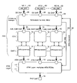
- FIG. 7 is a diagram illustrating various queues employed by the scheduling sublayer according to the first preferred embodiment
- FIG. 8 is a table exemplifying average latency in transmitting SDUs using the first preferred method and using a prior art round-robin multiplexing scheme
- FIG. 9 is a bandwidth occupancy chart corresponding to the example in FIG. 8 where SDUs are transmitted using the first preferred method
- FIG. 10 is a bandwidth occupancy chart corresponding to the example in FIG. 8 where SDUs are transmitted using the prior art round-robin multiplexing scheme
- FIG. 11 is a flow chart of a leaky bucket algorithm
- FIG. 12 is a bandwidth occupancy chart exemplifying a transmission pattern for non-real-time VBR VCs in accordance with the first preferred method
- FIG. 13 is a bandwidth occupancy chart exemplifying a transmission pattern for the same non-real-time VBR VCs shown in FIG. 12 but in accordance with a second preferred method for scheduling SDUs;
- FIGS. 14A and 14B are flowcharts illustrating the second preferred method, carried out by the scheduling sublayer, for servicing SDU data requests;
- FIG. 15 is a bandwidth occupancy chart illustrating a range of possible transmission times for PDUs of an SDU associated with a non-real-time VBR VC;
- FIG. 16 is a bandwidth occupancy chart exemplifying a transmission pattern for non-real-time VBR VCs in accordance with the second preferred method.
- FIG. 17 is a bandwidth occupancy chart exemplifying a transmission pattern for the same non-real-time VBR VCs shown FIG. 16 but in accordance with the first preferred method.
- the detailed description is divided into two parts.
- the first part discloses a preferred embodiment for minimizing the average latency per unit of AAL SDU data in relation to ATM service classes such as the available bit rate (ABR) and unspecified bit rate (UBR) service categories which are characterized by a peak cell rate (PCR) traffic management parameter.
- the second part discloses a preferred embodiment for minimizing the average latency per unit of AAL SDU data in relation to ATM service classes such as non-real-time VBR which are characterized by peak cell rate (PCR), sustained cell rate (SCR), and maximum burst size (MBS) traffic management parameters.
- PCR peak cell rate
- SCR sustained cell rate
- MFS maximum burst size
- FIG. 5 illustrates the structure of an AAL in accordance with the preferred embodiment.
- the preferred AAL includes a scheduling means, such as scheduling sublayer 24 (alternatively referred to as “SS”), located above the CS/SAR layers for scheduling or ordering the transfer of SDUs to the CS/SAR.
- scheduling sublayer 24 may be placed above the SAR but below the CS.
- the scheduling sublayer 24 provides a plurality of SS SAPs 26 , one for each VC associated with PHY SAP 14 .
- the scheduling sublayer 24 accepts AAL SDUs 22 in data requests from higher layers of the ATM protocol stack (hereinafter “AAL user”).
- AAL user uses the same data request to the scheduling sublayer at SS SAPs 26 as the AAL user would in the prior art for direct access to the AAL SAR SAP 15 .
- the scheduling sublayer 24 preferably communicates with the SAR 12 using prior art AAL SAR SAP 15 .
- the scheduling sublayer 24 affects only the egress data path (from AAL user to PHY) of SDUs 22 , but not the ingress data path (from PHY to AAL user).
- the scheduling sublayer 24 also communicates directly with the ATM Layer 11 through a cell rate specification signal 28 and an SDU transmission signal 30 .
- the cell rate signal 28 enables the scheduling sublayer 24 to specify a constant cell rate or period for any given VC to conventional ATM Layer equipment 11 ′ which, as known per se, provides this capability.
- the SDU transmission signal 30 enables the ATM Layer equipment 11 ′ to inform (such as by way of a software interrupt) the scheduling sublayer 24 when a last PDU of any given SDU 22 and VC has been transmitted. This capability is also provided by conventional ATM Layer equipment 11 ′, as known in the art per se, based upon examination of certain control bits in the PDU or when the equipment no longer has any cells to send for a particular connection.
- the scheduling sublayer 24 is provided with data regarding the traffic parameters, such as the PCR, and current transmit state of each VC; information which is typically known by the ATM Layer but not the CS/SAR.
- the scheduling sublayer 24 is also provided with data regarding SDU boundaries; information which is typically known by the CS/SAR but not the ATM Layer. This data is collectively used by the scheduling sublayer 24 to control the time at which SDUs 22 are passed to the CS/SAR, and to specify a constant cell rate for a given VC at the ATM Layer 11 .
- the scheduling sublayer 24 attempts to minimize the effects of the ATM Layer 11 which interleaves PDUs associated with various VCs in round-robin fashion for transport through PHY SAP 14 . This is accomplished by transferring the AAL SDUs of VCs to the CS/SAR layers on a substantially relative first-come, first-served basis (of VCs making data requests at SS SAPs 26 ) subject to the constraints that: (a) the PHY bandwidth consumed by the VCs are maximized within the limits of the bandwidth preallocated to their respective service classes; (b) the traffic parameters for each VC are satisfied; and (c) the SDUs, and the PDUs thereof, of any given VC be transmitted across PHY SAP 14 in sequential order so as to prevent misinsertion at the destination. This approach attempts to minimize the average transmission latency encountered by the AAL SDUs 22 .
- FIG. 4B The potential results in accordance with this approach are simplistically illustrated in FIG. 4B for the situation, corresponding to FIG. 4A , wherein two VCs each request the transmission of one SDU having the same number of PDUs at about the same time, with each VC having a PCR equal to 100% of the available bandwidth.
- each VC is given a maximal amount of bandwidth, i.e., up to its PCR, but the average latency is reduced compared to FIG. 4A .
- FIGS. 6A and 6B illustrate in flow chart form the preferred scheduling method carried out by the scheduling sublayer 24 .
- FIG. 7 illustrates various queues employed by the scheduling sublayer 24 .
- a TX list or queue 34 stores a list of VCs which are currently being transmitted by the CS/SAR and ATM Layer; that is, those VCs which have had an SDU (i.e., all of the PDUs thereof) passed to SAR 12 by the scheduling sublayer 24 .
- Queue 34 also stores the current cell rate for each VC listed therein.
- a TX-pending queue 36 stores a list of all VCs which have made data requests to the scheduling sublayer 24 , but the data requests and SDUs thereof have not yet been passed by the scheduling sublayer to AAL SAR SAP 15 .
- Event 40 ( FIG. 6A ) is the occurrence of a data request from the AAL user at any SS SAP 26 .
- Event 60 ( FIG. 6B ) is the communication of signal 30 by ATM Layer equipment 11 ′ to the scheduling sublayer 24 indicating that the equipment has finished transmitting an SDU (i.e., the last PDU thereof has been transmitted) for a given VC.
- the scheduling sublayer 24 checks at step 42 whether or not VC(i) is currently being serviced by it, i.e., if VC(i) is in the TX queue 34 or TX-pending queue 36 . If so, at step 46 , the scheduling sublayer 24 stores the SDU in a corresponding VC i queue 38 . These steps ensure that the AAL SDUs of a given VC are transferred to the CS/SAR in sequential order.
- step 44 If the condition at step 42 is not satisfied, then a check is made at step 44 whether or not there is any unused PHY bandwidth for the service class that VC(i) belongs to. If PHY bandwidth is available, then at steps 48 , 50 , 52 and 54 the scheduling sublayer 24 :
- VC(i) is added to the tail end of the TX-pending queue 36 and the SDU of VC(i) is added to the tail end of the corresponding VC i queue 38 .
- the scheduling sublayer 24 when the scheduling sublayer 24 receives an indication at event 60 that the ATM Layer 11 has finished sending all PDUs corresponding to an SDU of a given VC, VC(k), through the PRY SAP 14 , the SS 24 proceeds at step 62 to remove VC(k) from the TX queue 34 and update the PHY bandwidth availability for the service class that VC(k) belongs to.
- a check is made whether or not VC(k) has any AAL SDUs pending transmission, that is, if any SDUs are present in VC K queue 38 . If so, at step 66 VC(k) is placed on the TX-pending queue 36 .
- Steps 68 , 72 and 74 set up a loop for scanning the TX queue 34 , starting from its head.
- Step 70 determines whether the current cell rate of any VC, VC(x), in queue 34 can be increased. If so, at step 76 the scheduling sublayer 24 signals ATM Layer 11 to increase the current cell rate for VC(x) to the lower of: (i) the PCR of VC(x), and (ii) the remaining unused PHY bandwidth for the ATM service class that VC(x) belongs to. The available PHY bandwidth for that service class is also decreased accordingly.
- the TX queue 34 is scanned until the end of the queue or until the total PHY bandwidth available at PHY SAP 14 is exhausted.
- Steps 78 , 82 and 84 set up a loop for sequentially scanning the TX-pending queue 36 , starting from its head. If at step 80 PHY bandwidth remains available in the service class of a given VC, VC(x), at the head of queue 36 , then at step 86 the scheduling sublayer 24 removes VC(x) from TX-pending queue 36 . The scheduling sublayer 24 also removes the AAL SDU at the head of the corresponding VC x queue 38 , and processes the removed SDU as if a data request for VC(x) was received at the SS SAP 26 , as per steps 48 through 58 discussed above. The TX-pending queue 36 is scanned until the end of the queue or until the total PHY bandwidth available at PHY SAP 14 is exhausted.
- FIG. 8 is a table which specifies the VC identifier related to each data request, the time at which the request is made, the number of PDUs in the SDU, and the PCR for the VC.
- the VCs are assumed to belong to the same service class and the PCR is given as a percentage of the PHY bandwidth.
- the time has also been unitized so that one time unit is the length of time required for the PHY to send a single cell.
- FIG. 9 is a bandwidth occupancy chart illustrating the latency of each SDU that would likely result from the preferred scheduling method. This latency is the difference between the time a data request for the SDU was first made at SS SAP 26 and the time at which the last PDU for the SDU was sent by the ATM Layer to the PHY.
- FIG. 10 illustrates the latencies which would result under a typical prior art round-robin ATM Layer multiplexing scheme.
- VC 1 is allocated its PCR, and the ATM Layer is instructed to send the PDUs of VC 1 at 50%, of the PHY bandwidth.
- the SDU for VC 1 is passed to the SAR.
- VC 2 is allocated its PCR, and the ATM Layer is instructed to send the PDUs of VC 2 at 33% of the PHY bandwidth, and the SDU for VC 2 is passed to the SAR.
- VC 3 is allocated the remaining PHY bandwidth, and the SDU for VC 3 is passed to the SAR.
- VC 1 , VC 2 and VC 3 are added to the TX queue 34 of VCs whose SDU transmission is in progress.
- the scheduling sublayer adds VC 4 to the TX-pending queue 36 of VCs which have data requests pending. This state is also illustrated in FIG. 7A .
- VC 1 and VC 2 both complete transmission of all PDUs for their SDUs.
- the scheduling sublayer 24 removes these VCs from the TX queue 34 of VCs whose transmission is in progress, and the PHY is marked as having 83% of its bandwidth previously allocated to those VCs as free.
- the TX-pending queue 36 of VCs whose transmission is in progress is then scanned, and VC 3 is found to be operating below its PCR, so the ATM Layer is instructed to increase the PHY bandwidth allocated to VC 3 from 17% to 25%. Since there is still free PHY bandwidth, the TX-pending queue 36 of VCs with data requests pending is scanned.
- VC 4 is found, and the ATM Layer is instructed to allocate 75% of the PHY bandwidth to VC 4 —75% being both VC 4 's PCR and the previously remaining free PHY bandwidth—and the SDU for VC 4 is passed to the SAR. VC 4 is then added to the TX queue 34 of VCs whose transmission is in progress. This state is also illustrated in FIG. 7B .
- VC 4 completes transmission of PDUs for its SDU.
- VC 4 is therefore removed from the TX queue 34 of VCs whose transmission is in progress. Queue 34 is then scanned.
- VC 3 is found, but it is already transmitting at its PCR, so its transmission is not modified. There are no other VCs with data requests pending, so the PHY becomes 75% idle.
- VC 3 completes transmission.
- the preferred embodiment provides a number of advantages. First, it schedules SDUs to minimize the average amount of latency per unit of AAL SDU data on a given PHY. This results in effectively a lower average delay in data transmission through an ATM network. Second, the preferred method features a low storage and computational load, and can therefore be easily applied in real time systems. Third, the preferred embodiment strives to ensure that all available PHY bandwidth is consumed. Fourth, the preferred embodiment is not dependent on elaborate ATM Layer equipment. The only requirement of the ATM Layer equipment is that it be configurable so that the transmission rate of each connection or VC can be dynamically adjusted.
- the scheduling sublayer may use a separate timer to provide this indication. This is because the scheduling sublayer 24 is provided with the cell rate of each VC and the number of AAL PDUs to be sent on each connection. Therefore, the scheduling sublayer can compute the approximate time (i.e., ignoring cell delay variation introduced by ATM Layer multiplexing and PHY functions) at which the ATM Layer will finish sending the ATM PDUs to the PHY SAP.
- SDU i.e., two SDUs
- step 64 of the preferred method notes that VC 1 has an outstanding data request and thus places VC 1 on the TX-pending queue 36 , behind VC 4 .
- the (only) SDU of VC 4 is submitted to the CS/SAR by step 86 ahead of the second SDU of VC 1 , even though the latter physically arrived at the scheduling sublayer 24 prior to the former.
- the preferred method provides a means for ensuring that no VC is starved.
- the scheduling sublayer could implement a strict first-come first-served order per SDU, e.g., by transferring each SDU to the CS/SAR in the order of arrival as follows: (i) immediately, provided that bandwidth is available, or in due course, when bandwidth becomes available to the VC of that SDU or (ii) immediately, if the VC of that SDU is currently transmitting an SDU, thereby essentially changing the queuing point for such VCs to the ATM Layer.
- Such an embodiment may, however, risk starving a connection.
- the AAL places the scheduling sublayer 24 above the CS/SAR layers 12 and 13 . It should be appreciated that in alternative embodiments the scheduling sublayer 24 may be placed between the SAR layer 12 and the ATM layer 11 . In such an embodiment, the scheduling sublayer transfers groups of AAL SAR PDUs to the ATM layer 11 , wherein each group of AAL SAR PDUs corresponds to an AAL SDU. This embodiment yields an AAL having the same functionality as that of the preferred embodiment because the payload of the group of AAL SAR PDUs is in effect the AAL SDU.
- the embodiment described above operates well when the ATM virtual connections have traffic parameters such that they are always permitted to transmit at rates up to some peak cell rate.
- further optimization of the scheduling sublayer 24 can be obtained for the non-real-time variable bit rate (nrt-VBR) service category, where the rate at which a VC can transmit at a particular instant may vary between a specified sustainable cell rate and a peak cell rate.
- nrt-VBR non-real-time variable bit rate
- VBR VBR traffic contract
- PCR peak cell rate
- SCR sustainable cell rate
- MCS maximum burst size
- GCRA generic cell rate algorithm
- a VC is said to be compliant if the cell stream carried by that VC conforms to both GCRA (T S , ⁇ S ) and GCRA (T p , 0), where T S is the cell period at the SCR,
- T S 1 SCR )
- T p is the cell period at the PCR
- the essence of the non-real-time VBR traffic contract is that it explicitly allows a VC to transmit in a “bursty” fashion. That is, a nrt-VBR VC can transmit indefinitely at its SCR, and be in conformance with its traffic contract. Alternatively, the VC can cyclically transmit at rates above its SCR, up to its PCR, for a well-defined period, followed by another period during which it must transmit at rates below its SCR. This bursty transmission pattern is also in conformance with the nrt-VBR traffic contract.
- FIG. 12 is a bandwidth occupancy chart illustrating a transmission pattern that arises under the scheduling sublayer 24 of the first preferred embodiment for two nrt-VBR VCs.
- Each of these VCs has a set of AAL SDUs to send, with traffic parameters specifying an SCR of 50% of the PHY bandwidth and a PCR of 100% of the PHY bandwidth. It will be seen that each VC is continually sending at its SCR, and there is no burstiness in transmission.
- This transmission pattern is in conformance with the example nrt-VBR traffic contract, and the average latencies are noted on the chart.
- the second preferred embodiment improves upon the first preferred embodiment by modifying the scheduling sublayer 24 to schedule the transmission of an SDU such that the burstiness permitted by the nrt-VBR traffic contract is advantageously used to further reduce the average latency in the transmission of an SDU.
- This is done by scheduling the transmission of SDUs from various VCs such that the VCs may alternate between transmitting at rates approaching their PCRs and pausing their transmission, and by having the bursts in the transmission of each VC contain exactly one SDU.
- the transmission pattern under this approach is shown in FIG. 13 for the same example traffic contract described with reference to FIG. 12 . It will be seen that while one VC has paused its transmission, the other VC is sending at its PCR. This transmission pattern is highly bursty, but also conforms to the example nrt-VBR traffic contract.
- the second embodiment employs ATM Layer equipment 11 ′ which preferably has the following characteristics:
- FIGS. 14A and 14B show the preferred method carried out by the scheduling sublayer 24 in accordance with the second preferred embodiment. Those steps which have been added or modified in relation to FIGS. 6A and 6B of the first embodiment are shown in stippled outlines.
- the scheduling sublayer 24 stores two parameters, t and X, for each VC.
- X corresponds to the “fill level” of the GCRA(T S , ⁇ S ) “leaky bucket”, measured at time t.
- both X and t are zero.
- X and t are preferably recomputed by the scheduling sublayer 24 for each VC at two instants: (i) at a step 47 a ( FIG. 14A ), before the scheduling sublayer 24 passes (at step 52 ) a given SDU 22 to the CS/SAR 12 , and (ii) at a step 61 ( FIG. 14B ), after the scheduling sublayer 24 receives (at event 60 ) an indication that the transmission of the given SDU 22 is complete.
- X and t are calculated as follows: X ⁇ max(X ⁇ t now +t, 0) t ⁇ t now ⁇ 1 ⁇ where t now represents the time at which the calculation is performed. This calculation represents the “draining” of the leaky bucket in the period from t to t now , during which there was no transmission of PDUs for the VC.
- X and t are calculated as follows: X ⁇ max(X ⁇ t now +t+N*T S , 0) t ⁇ t now ⁇ 2 ⁇ where N is the number of PDUs (that is, the number of ATM cells) into which the given SDU was segmented by the SAR 12 . This calculation represents the “filling” of the leaky bucket in the period from t to t now , during which N PDUs were transmitted on the VC.
- the scheduling sublayer 24 When the scheduling sublayer 24 has a candidate SDU which could begin transmission immediately, it checks whether the first cell of that SDU would be conformant with GCRA(T S , ⁇ s ) if the SDU were transmitted immediately, i.e., if X ⁇ t now +t ⁇ S . Such a check occurs at step 47 b ( FIG. 14A ), which corresponds to the condition where an AAL user sends a data request to the scheduling sublayer 24 , PHY bandwidth is currently available, and queues 34 and 36 of pending SDUs for that VC are empty. This check also preferably occurs at step 81 a ( FIG. 14B ) which corresponds to the situation where another SDU has completed transmission and the scheduling sublayer is scanning the TX-pending queue 36 of VCs with pending SDUs.
- the scheduling sublayer 24 can pass the candidate SDU to the CS/SAR 12 for immediate transmission. If the check is not satisfied, the scheduling sublayer 24 cannot immediately begin transmitting the candidate SDU without violating GCRA(T S , ⁇ S ). Instead, in the case of a newly submitted SDU, at step 56 ′ the SDU is placed at the end of the queue 38 of pending SDUs for that VC, and that VC is placed on the TX-pending queue 36 of VCs which have pending SDUs. In the case where the scheduling sublayer 24 is scanning the TX-pending queue 36 of VCs with pending SDUs, queue 36 is left untouched. In either case, at steps 47 c ( FIG.
- the scheduling sublayer 24 starts a timer set to a period X ⁇ S ⁇ t now +t.
- this timer expires at event 79 ( FIG. 14B )
- the scheduling sublayer will again scan the TX-pending queue 36 of VCs with pending data requests.
- the former candidate SDU should be able to be transmitted in conformance with GCRA(T S , ⁇ S ).
- the scheduling sublayer Before the scheduling sublayer passes an SDU to the CS/SAR for transmission (step 52 ), at step 48 ′ the scheduling sublayer computes a cell period, T, (T being the inverse of the cell rate) which should be applied by the ATM Layer to the VC over the course of the transmission of the SDU.
- T being the inverse of the cell rate
- T is calculated according to:
- T L represents the period at which the remaining bandwidth of the PHY would be completely consumed by the transmission of this SDU.
- the first term of the above max( ) function represents the cell period which would cause the “bucket” of the VC to be completely filled at the end of the SDU's transmission. This implies that the SDU will be transmitted in as fast a burst as possible while still being in conformance with GCRA(T S , ⁇ S ).
- the scheduling sublayer 24 attempts at step 70 ′ to increase the cell rate, i.e., decrease the cell period, of any VCs with SDUs currently in transmission. To accommodate this, the scheduling sublayer 24 stores parameters X est ,R est and t est for each VC. These represent the estimated bucket fill level, the estimated number of cells remaining to transmit in the SDU, and the time of estimation, respectively.
- step 52 when the scheduling sublayer 24 passes an SDU to the CS/SAR for transmission, according to: X est ⁇ X, R est ⁇ N, t est ⁇ t ⁇ 4 ⁇ Thereafter, if the VC's cell period is adjusted while the SDU is in transmission, the new cell period is computed at step 70 ′ according to:
- the first term in the max( ) of equation ⁇ 5d ⁇ results in a cell period T such that the bucket will be full when the SDU's transmission is complete.
- est and R est are estimates of the bucket fill level and number of cells remaining to be transmitted in the SDU, based on the elapsed time since the last estimate (or since the SDU's transmission was requested to the SAR) and the cell period; they are not based on direct indications from the ATM layer or the SAR.
- the scheduling sublayer need not track X est , separately from X
- the scheduling sublayer need not track X est , separately from X
- X est should be distinguished from X only if the calculations during the transmission of an SDU are time based estimates and the calculations at the end of the transmission of an SDU are based on a direct indication from the ATM Layer. The advantage of this distinction is that any errors which may accumulate in the estimations are discarded when the direct indication is received at the ATM Layer.
- the scheduling sublayer 24 sorts the TX-pending queue 36 of VCs which have SDUs pending transmission according to increasing values of parameter t E : t E ⁇ X+t ⁇ 6 ⁇
- t E is simply the time at which the VC's bucket will be empty. This means that when one SDU's transmission has completed and another SDU's transmission may begin, the SDU selected to begin transmission will be the one on the VC whose bucket is emptiest.
- the VC with the emptiest bucket is that which can transmit at a cell rate closest to its PCR, and is therefore the VC which can achieve the most bursty transmission.
- Steps 56 ′ and 66 ′ attempt to maximize burstiness by taking advantage of the linearity of the GCRA.
- FIG. 15 there is a range of times when transmission of an SDU can begin which result in the same time for the completion of transmission of the last cell for that SDU, and hence the same latency therefor.
- the start of transmission of an AAL SDU is delayed such that the VC is not transmitting during that delay period, the VC's bucket will be emptying. This allows the SDU to eventually be transmitted at a cell rate approaching the PCR, which recoups the delay time.
- the increase in burstiness has no impact on that latency of the SDU.
- the scheduling sublayer 24 receives a data request on VC 1 for an SDU which will be segmented into 4 SAR PDUs, and immediately thereafter receives a data request on VC 2 for an SDU which will fit into a single SAR PDU.
- the scheduling sublayer receives another data request on VC 1 for an SDU which will be segmented into 3 SAR PDUs.
- the scheduling sublayer receives a data request on VC 3 for an SDU which will be segmented into 3 SAR PDUs. Assume that all VCs are in their initial state, with empty buckets, at time 0 .
- the scheduling sublayer proceeds as follows:
- the average transmission latency per unit of SDU data is then (4*4+2*1+4*3+7*3)/(4+1+3+3) ⁇ 4.6.
- the average transmission latency per unit of SDU data is then (4*4+2*1 +7*3+7*3)/(4+1+3+3) ⁇ 5.5—worse than is achieved when the queue of VCs with SDUs pending is sorted by increasing t E .
- t K be the time at which the K th conforming cell was transmitted on an ATM virtual connection
- X′ K be the trial value of the “leaky bucket counter” before the K th conforming cell was transmitted
- the SAR requests of the ATM layer that N ATM SDUs, that is, cells, be transmitted.
- the minimum values of t K+1 and t K+N that is, the earliest time at which the first and last of the N cells can be transmitted—can be calculated such that compliance to the traffic contract is guaranteed. Further, it can be shown that if N>1, the N cells can be transmitted at some rate with constant period T.
- the linarity of the GCRA guarantees that if the first and last of N cells are conforming, and all cells between the first and last are equally spaced, then all cells between the first and last will also be conforming.
- transmitting cells at a fixed rate with period T is but one of many possible transmission scenarios that would be compliant to a given traffic contract.
- t K+1 ⁇ max( t′ K+1 ,t K +T P , t K +X K ⁇ S ) ⁇ 8 ⁇
- the second term of the max( ) function in ⁇ 8 ⁇ assures compliance with GCRA(T p , 0); the last term assures compliance with GCRA(T S , ⁇ S )
- the first term is pro forma, and indicates that the ATM layer cannot send the first cell before the ATM layer user has requested it.
- X′ K+1 max( X K ⁇ t K+1 +t K ,0) ⁇ 9 ⁇
- the first term of the max( ) function in ⁇ 9 ⁇ corresponds to the case where there has not been sufficient time between t K and t k+1 to “empty the bucket”; the second (zero) term of the max( ) function indicates that there has been sufficient time between t K and t k+1 to “empty the bucket”.
- T must satisfy: ( N ⁇ 1)( T S ⁇ T )+ X′ K+1 ⁇ S ⁇ 10 ⁇
- the scheduling sublayer's per-VC parameter X immediately before the scheduling sublayer requests transmission of an AAL SDU of the SAR corresponds to X′ K+1 in this analysis; the parameter t corresponds to t K+1 in the analysis.
- the scheduling sublayer's per-VC parameter X corresponds to X K+N in this analysis; the parameter t corresponds to t K+N in the analysis.
- the minimum time at which the last conformant SAR PDU of an AAL SDU can be transmitted by the ATM layer is then t K+N , where:
- ⁇ 15 ⁇ means that t K+N is independent of t K+1 provided conditions ⁇ 14a ⁇ and ⁇ 14b ⁇ are met.
- the inequalities ⁇ 8 ⁇ , ⁇ 14a ⁇ and ⁇ 14b ⁇ can be combined with the definition of ⁇ S and rearranged as: X K +t k ⁇ S ⁇ t K+1 ⁇ X K +t k +min(( N ⁇ MBS)( T S ⁇ T P )0) ⁇ 16 ⁇
Abstract
Description
-
- (a) instructs the ATM Layer to set the current cell rate for VC(i) to the lower of: (i) the PCR of VC(i), and (ii) the remaining unused PHY bandwidth for the service class that VC(i) belongs to;
- (b) decreases the available PHY bandwidth for the service class that VC(i) belongs to by its current cell rate,
- (c) passes the SDU to the CS/SAR which, practically speaking, very quickly completes the segmentation of the SDU into PDUs and passes these to the ATM Layer for transmission; and
- (d) adds VC(i) to the tail end of the
TX queue 34.
Tp is the cell period at the PCR,
and τS is the burst tolerance, (τS=(MBS−1)*(TS−Tp)).
-
- Each VC whose cells are multiplexed by the ATM Layer may be assigned its own constant cell period. This cell period may be modified at any time by some other entity in the system, such as the
scheduling sublayer 24, but it is not otherwise modified by the ATM layer. - The ATM Layer performs cell multiplexing such that, for each opportunity it has to send a cell to the PHY, it may select a cell from any of the VCs for which it has candidate cells available for transmission, provided only that the interval between the current instant and the time at which the previous cell was transmitted for a particular VC is not less than the cell period specified for that VC.
- In the event that the cell period specified for a VC is modified by some entity such as the scheduling sublayer, the interval between the time at which the last cell was transmitted at the old cell period and the first cell is transmitted at the new cell period is not less than the lesser of the old and new cell periods.
- Each VC whose cells are multiplexed by the ATM Layer may be assigned its own constant cell period. This cell period may be modified at any time by some other entity in the system, such as the
X←max(X−tnow+t, 0)
t←tnow {1}
where tnow represents the time at which the calculation is performed. This calculation represents the “draining” of the leaky bucket in the period from t to tnow, during which there was no transmission of PDUs for the VC.
X←max(X−tnow+t+N*TS, 0)
t←tnow {2}
where N is the number of PDUs (that is, the number of ATM cells) into which the given SDU was segmented by the
where TL represents the period at which the remaining bandwidth of the PHY would be completely consumed by the transmission of this SDU. The first term of the above max( ) function represents the cell period which would cause the “bucket” of the VC to be completely filled at the end of the SDU's transmission. This implies that the SDU will be transmitted in as fast a burst as possible while still being in conformance with GCRA(TS, τS). (Note that X=τS implies that the bucket is full when the SDU's transmission begins, in which case the first term of the max( ) function simplifies to TS—when the bucket is full, the cell period cannot be less than the sustainable cell period.) The second term prevents the cell period from being less than the peak cell period. The third term prevents the VC from attempting to consume more PHY bandwidth than exists.
T←max(Tp, TL) {3b}
Xest←X, R est←N, test←t {4}
Thereafter, if the VC's cell period is adjusted while the SDU is in transmission, the new cell period is computed at
tE←X+t {6}
- tnow=0: First, the scheduling sublayer verifies that
VC 1 is GCRA(TS, τS) compliant, i.e., that X−tnow+t≦τS forVC 1. Since this condition is met,VC 1 can begin transmission of an AAL SDU immediately. The scheduling sublayer then computes (X, t)=(0, 0) forVC 1. The period at which PDUs should be transmitted for this SDU is, from equation {3a}, given by:
-
- In other words, the scheduling sublayer will tell the ATM Layer to set the cell rate of
VC 1 to 100% of the PHY bandwidth, and will request the transmission of the SDU forVC 1 to the SAR. - Also, since all the PHY bandwidth has been allocated at this time, the SDU requested for
VC 2 is added to the end of the VC2 queue 38 b of pending SDUs forVC 2, andVC 2 is placed on the TX-pendingqueue 36 for VCs having pending data requests, with tE=0.
- In other words, the scheduling sublayer will tell the ATM Layer to set the cell rate of
- tnow=4: The transmission of the SDU for
VC 1 is completed. The parameters (X, t)=(0−4+0+2*4, 4)=(4, 4) are stored againstVC 1. The transmission latency for this SDU is 4.- There are no other VCs with SDUs in transmission. The TX-pending
queue 36 of VCs having pending data requests is scanned, findingVC 2. ForVC 2, the condition X−tnow+t≦τS is met, so transmission may begin. The parameters (X, t)=(0, 4) are computed forVC 2. Since N=1 for the SDU requested onVC 2, the transmission of the SDU occurs at the peak cell period of 1. Thescheduling sublayer 24 thus signals theATM Layer 11 to set the cell rate ofVC 2 to 100% of the PHY bandwidth, and will request the transmission of the SDU forVC 2 to theSAR 12.
- There are no other VCs with SDUs in transmission. The TX-pending
- tnow=4+: Next, the scheduling sublayer receives the data request for the second SDU on
VC 1. Since there is no unused PHY bandwidth remaining, the SDU requested forVC 1 is added to the end of VC1 queue 38 a of pending SDUs forVC 1, andVC 1 is placed on the TX-pendingqueue 36 for VCs with pending SDU data requests, with tE=X+t=8.- Finally, the scheduling sublayer receives the data request for the SDU of
VC 3. Since there is no unused PHY bandwidth remaining, the SDU forVC 3 is added to the end of the VC3 queue 38 c of pending SDUs forVC 3, andVC 3 is placed on the TX-pendingqueue 36 of VCs with pending SDUs. Since the tE value forVC 3 is 0, which is lower than the tE value for VC 1 (tE=8 for VC 1),VC 3 is inserted beforeVC 1 on the TX-pendingqueue 36 for VCs having SDU data requests pending, in accordance withstep 66′.
- Finally, the scheduling sublayer receives the data request for the SDU of
- tnow=5: The transmission of the SDU for
VC 2 is completed. The parameters (X, t)=(0−5+4+2*1, 5)=(1, 5) are stored againstVC 2. The transmission latency for this SDU is 2.- There are no other VCs with SDUs in transmission. The TX-pending
queue 36 of VCs having pending SDUs is scanned, findingVC 3 first. ForVC 3, the condition X−tnow+t≦τS is met, so transmission may begin. The parameters (X, t)=(0, 5) are computed forVC 3. The period at which PDUs should be transmitted for the SDU ofVC 3 is given by:
- There are no other VCs with SDUs in transmission. The TX-pending
-
- The scheduling sublayer thus signals the ATM layer to set the cell rate of
VC 3 to 100% of the PHY bandwidth, and will request the transmission of the SDU forVC 3 to the SAR.
- The scheduling sublayer thus signals the ATM layer to set the cell rate of
- tnow=8: The transmission of the SDU for
VC 3 is completed. The parameters (X, t)=(0−8+5+2*3, 8)=(3, 8) are stored againstVC 3. The transmission latency for this SDU is 4.- There are no other VCs with SDUs in transmission. The TX-pending
queue 36 of VCs having pending SDU data requests is scanned, findingVC 1. ForVC 1, the condition X−tnow+t≦τS is met, so transmission may begin. The parameters (X, t)=(4−8+4, 8)=(0, 8) are computed forVC 1. The period at which PDUs should be transmitted for the SDU ofVC 3 is given by:
- There are no other VCs with SDUs in transmission. The TX-pending
-
- The scheduling sublayer thus signals the ATM Layer to set the cell rate of
VC 1 to 100% of the PHY bandwidth, and will request the transmission of the second SDU forVC 1 to the SAR.
- The scheduling sublayer thus signals the ATM Layer to set the cell rate of
- tnow=11: The transmission of the second SDU for
VC 1 is completed. The parameters (X, t)=(0−11+8+2*3, 11)=(3, 11) are stored againstVC 3. The transmission latency for this SDU is 7.
- tnow=5: The transmission of the SDU for
VC 2 is completed. The parameters (X, t)=(0−5+4+2*1, 5)=(1, 5) are stored againstVC 2. The transmission latency for this SDU is 2.- There are no other VCs with SDUs in transmission. The TX-pending
queue 36 of VCs with pending SDUs is scanned, findingVC 1 first. ForVC 1, the condition X−tnow+t≦τs is met, so transmission may begin. The parameters (X, t)=(4−5+4, 5)=(3, 5) are computed forVC 1. The period at which PDUs should be transmitted for the second SDU ofVC 1 is given by:
- There are no other VCs with SDUs in transmission. The TX-pending
-
- The scheduling sublayer thus instructs the ATM Layer to set the cell rate of
VC 1 to 50% of the PHY bandwidth, and will request the transmission of the second SDU forVC 1 to the SAR. - Fifty percent of the PHY bandwidth remains unused, so the scanning of the TX-pending
queue 36 of VCs with SDUs pending continues.VC 3 is found. ForVC 3, the condition X−tnow+t≦τS is met, so transmission may begin. The parameters (X, t)=(0, 5) are computed forVC 3. The period at which PDUs should be transmitted forVC 3's SDU is given by:
- The scheduling sublayer thus instructs the ATM Layer to set the cell rate of
-
- This time, the limitation of the bandwidth allocated to
VC 3 is not imposed by GCRA conformance, but by the limited amount of PHY bandwidth remaining. The scheduling sublayer thus instructs the ATM Layer to set the cell rate ofVC 3 to 50% of the PHY bandwidth, and will request the transmission of the SDU forVC 3 to the SAR.
- This time, the limitation of the bandwidth allocated to
- tnow=11: The transmission of the second SDU for
VC 1 and the SDU forVC 3 are both completed. The parameters (X, t)=(3−11+5+2*3, 11)=(3, 11) are stored againstVC 1; the parameters (X, t)=(0−11+5+2*3, 11)=(0, 11) are stored againstVC 3. The transmission latency for both SDUs is 7.
X K =X′ K +T S {7}
t K+1≧max(t′ K+1 ,t K +T P , t K +X K−τS) {8}
X′ K+1=max(X K −t K+1 +t K,0) {9}
(N−1)(T S −T)+X′ K+1 ≦τ S {10}
X K+N =NT S−(N−1)T+X′ K+1 {12}
X K +t k−τS ≦t K+1 ≦X K +t k+min((N−MBS)(T S −T P)0) {16}
Claims (32)
Priority Applications (1)
| Application Number | Priority Date | Filing Date | Title |
|---|---|---|---|
| US10/126,527 US7295558B2 (en) | 1998-03-30 | 2002-04-22 | ATM adaption layer traffic scheduling |
Applications Claiming Priority (4)
| Application Number | Priority Date | Filing Date | Title |
|---|---|---|---|
| CA2,233,491 | 1998-03-30 | ||
| CA002233491A CA2233491A1 (en) | 1998-03-30 | 1998-03-30 | Atm adaption layer traffic scheduling |
| US09/208,982 US6392994B1 (en) | 1998-03-30 | 1998-12-11 | ATM adaption layer traffic scheduling |
| US10/126,527 US7295558B2 (en) | 1998-03-30 | 2002-04-22 | ATM adaption layer traffic scheduling |
Related Parent Applications (1)
| Application Number | Title | Priority Date | Filing Date |
|---|---|---|---|
| US09/208,982 Continuation US6392994B1 (en) | 1998-03-30 | 1998-12-11 | ATM adaption layer traffic scheduling |
Publications (2)
| Publication Number | Publication Date |
|---|---|
| US20020150046A1 US20020150046A1 (en) | 2002-10-17 |
| US7295558B2 true US7295558B2 (en) | 2007-11-13 |
Family
ID=25680111
Family Applications (1)
| Application Number | Title | Priority Date | Filing Date |
|---|---|---|---|
| US10/126,527 Expired - Lifetime US7295558B2 (en) | 1998-03-30 | 2002-04-22 | ATM adaption layer traffic scheduling |
Country Status (2)
| Country | Link |
|---|---|
| US (1) | US7295558B2 (en) |
| EP (1) | EP0952752B1 (en) |
Cited By (4)
| Publication number | Priority date | Publication date | Assignee | Title |
|---|---|---|---|---|
| US20050190697A1 (en) * | 2004-03-01 | 2005-09-01 | Masahiro Dohi | Transmission control system using link aggregation |
| US20060019677A1 (en) * | 2004-07-20 | 2006-01-26 | Teague Edward H | Packet aware scheduler in wireless communication systems |
| US20060209687A1 (en) * | 2005-03-18 | 2006-09-21 | Fujitsu Limited | Communication rate control method and device |
| US20080137666A1 (en) * | 2006-12-06 | 2008-06-12 | Applied Micro Circuits Corporation | Cut-through information scheduler |
Families Citing this family (4)
| Publication number | Priority date | Publication date | Assignee | Title |
|---|---|---|---|---|
| US6876668B1 (en) * | 1999-05-24 | 2005-04-05 | Cisco Technology, Inc. | Apparatus and methods for dynamic bandwidth allocation |
| US20050286529A1 (en) * | 2004-06-29 | 2005-12-29 | Ambalavanar Arulambalam | Method and apparatus for ATM adaptation layer staggered constant bit rate cell scheduling |
| US8817826B2 (en) * | 2009-05-29 | 2014-08-26 | Lsi Corporation | Aggregating lower bandwidth asynchronously clocked communication links into a higher bandwidth link |
| US9565138B2 (en) | 2013-12-20 | 2017-02-07 | Brocade Communications Systems, Inc. | Rule-based network traffic interception and distribution scheme |
Citations (13)
| Publication number | Priority date | Publication date | Assignee | Title |
|---|---|---|---|---|
| US5533020A (en) | 1994-10-31 | 1996-07-02 | International Business Machines Corporation | ATM cell scheduler |
| US5687167A (en) | 1994-11-24 | 1997-11-11 | International Business Machines Corporation | Method for preempting connections in high speed packet switching networks |
| US5838681A (en) | 1996-01-24 | 1998-11-17 | Bonomi; Flavio | Dynamic allocation of port bandwidth in high speed packet-switched digital switching systems |
| US5889779A (en) | 1996-12-02 | 1999-03-30 | Rockwell Science Center | Scheduler utilizing dynamic schedule table |
| US5987031A (en) | 1997-05-22 | 1999-11-16 | Integrated Device Technology, Inc. | Method for fair dynamic scheduling of available bandwidth rate (ABR) service under asynchronous transfer mode (ATM) |
| US6003062A (en) | 1997-07-16 | 1999-12-14 | Fore Systems, Inc. | Iterative algorithm for performing max min fair allocation |
| US6041039A (en) | 1997-03-20 | 2000-03-21 | Nokia Telecommunications, Oy | System and method for determining network bandwidth availability using priority level feedback |
| US6081513A (en) * | 1997-02-10 | 2000-06-27 | At&T Corp. | Providing multimedia conferencing services over a wide area network interconnecting nonguaranteed quality of services LANs |
| US6205152B1 (en) | 1997-12-31 | 2001-03-20 | Samsung Electronics Co., Ltd. | Frame relay-to-ATM interface circuit and method of operation |
| US6240066B1 (en) * | 1997-02-11 | 2001-05-29 | Lucent Technologies Inc. | Dynamic bandwidth and buffer management algorithm for multi-service ATM switches |
| US6272109B1 (en) * | 1997-11-18 | 2001-08-07 | Cabletron Systems, Inc. | Hierarchical schedules for different ATM traffic |
| US6304549B1 (en) * | 1996-09-12 | 2001-10-16 | Lucent Technologies Inc. | Virtual path management in hierarchical ATM networks |
| US6392994B1 (en) * | 1998-03-30 | 2002-05-21 | Alcatel Canada Inc. | ATM adaption layer traffic scheduling |
-
1999
- 1999-03-25 EP EP99106050.0A patent/EP0952752B1/en not_active Expired - Lifetime
-
2002
- 2002-04-22 US US10/126,527 patent/US7295558B2/en not_active Expired - Lifetime
Patent Citations (13)
| Publication number | Priority date | Publication date | Assignee | Title |
|---|---|---|---|---|
| US5533020A (en) | 1994-10-31 | 1996-07-02 | International Business Machines Corporation | ATM cell scheduler |
| US5687167A (en) | 1994-11-24 | 1997-11-11 | International Business Machines Corporation | Method for preempting connections in high speed packet switching networks |
| US5838681A (en) | 1996-01-24 | 1998-11-17 | Bonomi; Flavio | Dynamic allocation of port bandwidth in high speed packet-switched digital switching systems |
| US6304549B1 (en) * | 1996-09-12 | 2001-10-16 | Lucent Technologies Inc. | Virtual path management in hierarchical ATM networks |
| US5889779A (en) | 1996-12-02 | 1999-03-30 | Rockwell Science Center | Scheduler utilizing dynamic schedule table |
| US6081513A (en) * | 1997-02-10 | 2000-06-27 | At&T Corp. | Providing multimedia conferencing services over a wide area network interconnecting nonguaranteed quality of services LANs |
| US6240066B1 (en) * | 1997-02-11 | 2001-05-29 | Lucent Technologies Inc. | Dynamic bandwidth and buffer management algorithm for multi-service ATM switches |
| US6041039A (en) | 1997-03-20 | 2000-03-21 | Nokia Telecommunications, Oy | System and method for determining network bandwidth availability using priority level feedback |
| US5987031A (en) | 1997-05-22 | 1999-11-16 | Integrated Device Technology, Inc. | Method for fair dynamic scheduling of available bandwidth rate (ABR) service under asynchronous transfer mode (ATM) |
| US6003062A (en) | 1997-07-16 | 1999-12-14 | Fore Systems, Inc. | Iterative algorithm for performing max min fair allocation |
| US6272109B1 (en) * | 1997-11-18 | 2001-08-07 | Cabletron Systems, Inc. | Hierarchical schedules for different ATM traffic |
| US6205152B1 (en) | 1997-12-31 | 2001-03-20 | Samsung Electronics Co., Ltd. | Frame relay-to-ATM interface circuit and method of operation |
| US6392994B1 (en) * | 1998-03-30 | 2002-05-21 | Alcatel Canada Inc. | ATM adaption layer traffic scheduling |
Non-Patent Citations (2)
| Title |
|---|
| Tranchier, D. P. et al., "Fast Bandwidth Allocation in ATM Networks", Proceedings of the International Switching Symposium, Tokyo, Japan, IEICE, vol. AYMP. 14, Oct. 25, 1992, pates 7-11, XP000337692. |
| Xie, G. G. et al., "Real-Time Block Transfer Under a Link-Sharing Hierarchy", IEEE/ACM Transactions on Networking, IEEE Inc., New York, United States, vol. 6, No. 1, Feb. 1, 1998, pp. 30-41, XP000733549. |
Cited By (7)
| Publication number | Priority date | Publication date | Assignee | Title |
|---|---|---|---|---|
| US20050190697A1 (en) * | 2004-03-01 | 2005-09-01 | Masahiro Dohi | Transmission control system using link aggregation |
| US20060019677A1 (en) * | 2004-07-20 | 2006-01-26 | Teague Edward H | Packet aware scheduler in wireless communication systems |
| US7961609B2 (en) * | 2004-07-20 | 2011-06-14 | Qualcomm Incorporated | Packet aware scheduler in wireless communication systems |
| US20110205987A1 (en) * | 2004-07-20 | 2011-08-25 | Qualcomm Incorporated | Packet aware scheduler in wireless communication systems |
| US8971259B2 (en) | 2004-07-20 | 2015-03-03 | Qualcomm Incorporated | Packet aware scheduler in wireless communication systems |
| US20060209687A1 (en) * | 2005-03-18 | 2006-09-21 | Fujitsu Limited | Communication rate control method and device |
| US20080137666A1 (en) * | 2006-12-06 | 2008-06-12 | Applied Micro Circuits Corporation | Cut-through information scheduler |
Also Published As
| Publication number | Publication date |
|---|---|
| EP0952752B1 (en) | 2013-05-15 |
| EP0952752A3 (en) | 2000-12-27 |
| US20020150046A1 (en) | 2002-10-17 |
| EP0952752A2 (en) | 1999-10-27 |
Similar Documents
| Publication | Publication Date | Title |
|---|---|---|
| US6392994B1 (en) | ATM adaption layer traffic scheduling | |
| EP0901301B1 (en) | Dynamic rate control scheduler for ATM networks | |
| JP3813695B2 (en) | Packet switched communication system | |
| US6747976B1 (en) | Distributed scheduling architecture with efficient reservation protocol and dynamic priority scheme for wireless ATM networks | |
| EP0862299B1 (en) | Multi-class connection admission control method for asynchronous transfer mode (ATM) switches | |
| US5712851A (en) | Adaptive time slot scheduling apparatus and method utilizing a linked list mechanism | |
| CA2118471C (en) | Upc-based traffic control framework for atm networks | |
| JP3813697B2 (en) | Traffic molding equipment | |
| JP3813696B2 (en) | Packet switched communication system | |
| EP0916214B1 (en) | Method and apparatus for source rate pacing in an atm network | |
| US5831971A (en) | Method for leaky bucket traffic shaping using fair queueing collision arbitration | |
| US6396834B1 (en) | Flexible scheduler in an asynchronous transfer mode (ATM) switch | |
| US6198724B1 (en) | ATM cell scheduling method and apparatus | |
| US6442164B1 (en) | Method and system for allocating bandwidth and buffer resources to constant bit rate (CBR) traffic | |
| US6396843B1 (en) | Method and apparatus for guaranteeing data transfer rates and delays in data packet networks using logarithmic calendar queues | |
| US6587436B1 (en) | Method and apparatus for allocation of available bandwidth | |
| US6243359B1 (en) | Methods and apparatus for managing traffic in an atm network | |
| US7295558B2 (en) | ATM adaption layer traffic scheduling | |
| US6359862B1 (en) | ATM network available bit rate (ABR) explicit rate flow control system | |
| US6603766B1 (en) | Apparatus and method for implementing an ATM AAL2 combined use timer | |
| EP0952753B1 (en) | ATM adaption layer traffic scheduling for variable bit rate connections | |
| US6542509B1 (en) | Virtual path level fairness | |
| US6529474B1 (en) | Shaping algorithm | |
| US20050286529A1 (en) | Method and apparatus for ATM adaptation layer staggered constant bit rate cell scheduling | |
| CA2267475A1 (en) | Atm adaptation layer traffic scheduling |
Legal Events
| Date | Code | Title | Description |
|---|---|---|---|
| STCF | Information on status: patent grant |
Free format text: PATENTED CASE |
|
| CC | Certificate of correction | ||
| FEPP | Fee payment procedure |
Free format text: PAYOR NUMBER ASSIGNED (ORIGINAL EVENT CODE: ASPN); ENTITY STATUS OF PATENT OWNER: LARGE ENTITY |
|
| FPAY | Fee payment |
Year of fee payment: 4 |
|
| AS | Assignment |
Owner name: CREDIT SUISSE AG, NEW YORK Free format text: SECURITY INTEREST;ASSIGNOR:ALCATEL-LUCENT CANADA INC.;REEL/FRAME:029826/0927 Effective date: 20130130 |
|
| AS | Assignment |
Owner name: ALCATEL-LUCENT CANADA INC., CANADA Free format text: RELEASE OF SECURITY INTEREST;ASSIGNOR:CREDIT SUISSE AG;REEL/FRAME:033686/0798 Effective date: 20140819 |
|
| FPAY | Fee payment |
Year of fee payment: 8 |
|
| MAFP | Maintenance fee payment |
Free format text: PAYMENT OF MAINTENANCE FEE, 12TH YEAR, LARGE ENTITY (ORIGINAL EVENT CODE: M1553); ENTITY STATUS OF PATENT OWNER: LARGE ENTITY Year of fee payment: 12 |