US7291093B2 - Power output apparatus, control system for power output apparatus, and control method of power output apparatus - Google Patents
Power output apparatus, control system for power output apparatus, and control method of power output apparatus Download PDFInfo
- Publication number
- US7291093B2 US7291093B2 US11/293,389 US29338905A US7291093B2 US 7291093 B2 US7291093 B2 US 7291093B2 US 29338905 A US29338905 A US 29338905A US 7291093 B2 US7291093 B2 US 7291093B2
- Authority
- US
- United States
- Prior art keywords
- internal combustion
- combustion engine
- gear ratio
- power
- transmission mechanism
- Prior art date
- Legal status (The legal status is an assumption and is not a legal conclusion. Google has not performed a legal analysis and makes no representation as to the accuracy of the status listed.)
- Active, expires
Links
Images


Classifications
-
- B—PERFORMING OPERATIONS; TRANSPORTING
- B60—VEHICLES IN GENERAL
- B60K—ARRANGEMENT OR MOUNTING OF PROPULSION UNITS OR OF TRANSMISSIONS IN VEHICLES; ARRANGEMENT OR MOUNTING OF PLURAL DIVERSE PRIME-MOVERS IN VEHICLES; AUXILIARY DRIVES FOR VEHICLES; INSTRUMENTATION OR DASHBOARDS FOR VEHICLES; ARRANGEMENTS IN CONNECTION WITH COOLING, AIR INTAKE, GAS EXHAUST OR FUEL SUPPLY OF PROPULSION UNITS IN VEHICLES
- B60K6/00—Arrangement or mounting of plural diverse prime-movers for mutual or common propulsion, e.g. hybrid propulsion systems comprising electric motors and internal combustion engines ; Control systems therefor, i.e. systems controlling two or more prime movers, or controlling one of these prime movers and any of the transmission, drive or drive units Informative references: mechanical gearings with secondary electric drive F16H3/72; arrangements for handling mechanical energy structurally associated with the dynamo-electric machine H02K7/00; machines comprising structurally interrelated motor and generator parts H02K51/00; dynamo-electric machines not otherwise provided for in H02K see H02K99/00
- B60K6/20—Arrangement or mounting of plural diverse prime-movers for mutual or common propulsion, e.g. hybrid propulsion systems comprising electric motors and internal combustion engines ; Control systems therefor, i.e. systems controlling two or more prime movers, or controlling one of these prime movers and any of the transmission, drive or drive units Informative references: mechanical gearings with secondary electric drive F16H3/72; arrangements for handling mechanical energy structurally associated with the dynamo-electric machine H02K7/00; machines comprising structurally interrelated motor and generator parts H02K51/00; dynamo-electric machines not otherwise provided for in H02K see H02K99/00 the prime-movers consisting of electric motors and internal combustion engines, e.g. HEVs
- B60K6/22—Arrangement or mounting of plural diverse prime-movers for mutual or common propulsion, e.g. hybrid propulsion systems comprising electric motors and internal combustion engines ; Control systems therefor, i.e. systems controlling two or more prime movers, or controlling one of these prime movers and any of the transmission, drive or drive units Informative references: mechanical gearings with secondary electric drive F16H3/72; arrangements for handling mechanical energy structurally associated with the dynamo-electric machine H02K7/00; machines comprising structurally interrelated motor and generator parts H02K51/00; dynamo-electric machines not otherwise provided for in H02K see H02K99/00 the prime-movers consisting of electric motors and internal combustion engines, e.g. HEVs characterised by apparatus, components or means specially adapted for HEVs
- B60K6/36—Arrangement or mounting of plural diverse prime-movers for mutual or common propulsion, e.g. hybrid propulsion systems comprising electric motors and internal combustion engines ; Control systems therefor, i.e. systems controlling two or more prime movers, or controlling one of these prime movers and any of the transmission, drive or drive units Informative references: mechanical gearings with secondary electric drive F16H3/72; arrangements for handling mechanical energy structurally associated with the dynamo-electric machine H02K7/00; machines comprising structurally interrelated motor and generator parts H02K51/00; dynamo-electric machines not otherwise provided for in H02K see H02K99/00 the prime-movers consisting of electric motors and internal combustion engines, e.g. HEVs characterised by apparatus, components or means specially adapted for HEVs characterised by the transmission gearings
- B60K6/365—Arrangement or mounting of plural diverse prime-movers for mutual or common propulsion, e.g. hybrid propulsion systems comprising electric motors and internal combustion engines ; Control systems therefor, i.e. systems controlling two or more prime movers, or controlling one of these prime movers and any of the transmission, drive or drive units Informative references: mechanical gearings with secondary electric drive F16H3/72; arrangements for handling mechanical energy structurally associated with the dynamo-electric machine H02K7/00; machines comprising structurally interrelated motor and generator parts H02K51/00; dynamo-electric machines not otherwise provided for in H02K see H02K99/00 the prime-movers consisting of electric motors and internal combustion engines, e.g. HEVs characterised by apparatus, components or means specially adapted for HEVs characterised by the transmission gearings with the gears having orbital motion
-
- B—PERFORMING OPERATIONS; TRANSPORTING
- B60—VEHICLES IN GENERAL
- B60W—CONJOINT CONTROL OF VEHICLE SUB-UNITS OF DIFFERENT TYPE OR DIFFERENT FUNCTION; CONTROL SYSTEMS SPECIALLY ADAPTED FOR HYBRID VEHICLES; ROAD VEHICLE DRIVE CONTROL SYSTEMS FOR PURPOSES NOT RELATED TO THE CONTROL OF A PARTICULAR SUB-UNIT
- B60W20/00—Control systems specially adapted for hybrid vehicles
- B60W20/30—Control strategies involving selection of transmission gear ratio
-
- B—PERFORMING OPERATIONS; TRANSPORTING
- B60—VEHICLES IN GENERAL
- B60K—ARRANGEMENT OR MOUNTING OF PROPULSION UNITS OR OF TRANSMISSIONS IN VEHICLES; ARRANGEMENT OR MOUNTING OF PLURAL DIVERSE PRIME-MOVERS IN VEHICLES; AUXILIARY DRIVES FOR VEHICLES; INSTRUMENTATION OR DASHBOARDS FOR VEHICLES; ARRANGEMENTS IN CONNECTION WITH COOLING, AIR INTAKE, GAS EXHAUST OR FUEL SUPPLY OF PROPULSION UNITS IN VEHICLES
- B60K6/00—Arrangement or mounting of plural diverse prime-movers for mutual or common propulsion, e.g. hybrid propulsion systems comprising electric motors and internal combustion engines ; Control systems therefor, i.e. systems controlling two or more prime movers, or controlling one of these prime movers and any of the transmission, drive or drive units Informative references: mechanical gearings with secondary electric drive F16H3/72; arrangements for handling mechanical energy structurally associated with the dynamo-electric machine H02K7/00; machines comprising structurally interrelated motor and generator parts H02K51/00; dynamo-electric machines not otherwise provided for in H02K see H02K99/00
- B60K6/20—Arrangement or mounting of plural diverse prime-movers for mutual or common propulsion, e.g. hybrid propulsion systems comprising electric motors and internal combustion engines ; Control systems therefor, i.e. systems controlling two or more prime movers, or controlling one of these prime movers and any of the transmission, drive or drive units Informative references: mechanical gearings with secondary electric drive F16H3/72; arrangements for handling mechanical energy structurally associated with the dynamo-electric machine H02K7/00; machines comprising structurally interrelated motor and generator parts H02K51/00; dynamo-electric machines not otherwise provided for in H02K see H02K99/00 the prime-movers consisting of electric motors and internal combustion engines, e.g. HEVs
- B60K6/22—Arrangement or mounting of plural diverse prime-movers for mutual or common propulsion, e.g. hybrid propulsion systems comprising electric motors and internal combustion engines ; Control systems therefor, i.e. systems controlling two or more prime movers, or controlling one of these prime movers and any of the transmission, drive or drive units Informative references: mechanical gearings with secondary electric drive F16H3/72; arrangements for handling mechanical energy structurally associated with the dynamo-electric machine H02K7/00; machines comprising structurally interrelated motor and generator parts H02K51/00; dynamo-electric machines not otherwise provided for in H02K see H02K99/00 the prime-movers consisting of electric motors and internal combustion engines, e.g. HEVs characterised by apparatus, components or means specially adapted for HEVs
- B60K6/40—Arrangement or mounting of plural diverse prime-movers for mutual or common propulsion, e.g. hybrid propulsion systems comprising electric motors and internal combustion engines ; Control systems therefor, i.e. systems controlling two or more prime movers, or controlling one of these prime movers and any of the transmission, drive or drive units Informative references: mechanical gearings with secondary electric drive F16H3/72; arrangements for handling mechanical energy structurally associated with the dynamo-electric machine H02K7/00; machines comprising structurally interrelated motor and generator parts H02K51/00; dynamo-electric machines not otherwise provided for in H02K see H02K99/00 the prime-movers consisting of electric motors and internal combustion engines, e.g. HEVs characterised by apparatus, components or means specially adapted for HEVs characterised by the assembly or relative disposition of components
- B60K6/405—Housings
-
- B—PERFORMING OPERATIONS; TRANSPORTING
- B60—VEHICLES IN GENERAL
- B60K—ARRANGEMENT OR MOUNTING OF PROPULSION UNITS OR OF TRANSMISSIONS IN VEHICLES; ARRANGEMENT OR MOUNTING OF PLURAL DIVERSE PRIME-MOVERS IN VEHICLES; AUXILIARY DRIVES FOR VEHICLES; INSTRUMENTATION OR DASHBOARDS FOR VEHICLES; ARRANGEMENTS IN CONNECTION WITH COOLING, AIR INTAKE, GAS EXHAUST OR FUEL SUPPLY OF PROPULSION UNITS IN VEHICLES
- B60K6/00—Arrangement or mounting of plural diverse prime-movers for mutual or common propulsion, e.g. hybrid propulsion systems comprising electric motors and internal combustion engines ; Control systems therefor, i.e. systems controlling two or more prime movers, or controlling one of these prime movers and any of the transmission, drive or drive units Informative references: mechanical gearings with secondary electric drive F16H3/72; arrangements for handling mechanical energy structurally associated with the dynamo-electric machine H02K7/00; machines comprising structurally interrelated motor and generator parts H02K51/00; dynamo-electric machines not otherwise provided for in H02K see H02K99/00
- B60K6/20—Arrangement or mounting of plural diverse prime-movers for mutual or common propulsion, e.g. hybrid propulsion systems comprising electric motors and internal combustion engines ; Control systems therefor, i.e. systems controlling two or more prime movers, or controlling one of these prime movers and any of the transmission, drive or drive units Informative references: mechanical gearings with secondary electric drive F16H3/72; arrangements for handling mechanical energy structurally associated with the dynamo-electric machine H02K7/00; machines comprising structurally interrelated motor and generator parts H02K51/00; dynamo-electric machines not otherwise provided for in H02K see H02K99/00 the prime-movers consisting of electric motors and internal combustion engines, e.g. HEVs
- B60K6/42—Arrangement or mounting of plural diverse prime-movers for mutual or common propulsion, e.g. hybrid propulsion systems comprising electric motors and internal combustion engines ; Control systems therefor, i.e. systems controlling two or more prime movers, or controlling one of these prime movers and any of the transmission, drive or drive units Informative references: mechanical gearings with secondary electric drive F16H3/72; arrangements for handling mechanical energy structurally associated with the dynamo-electric machine H02K7/00; machines comprising structurally interrelated motor and generator parts H02K51/00; dynamo-electric machines not otherwise provided for in H02K see H02K99/00 the prime-movers consisting of electric motors and internal combustion engines, e.g. HEVs characterised by the architecture of the hybrid electric vehicle
- B60K6/44—Series-parallel type
- B60K6/445—Differential gearing distribution type
-
- B—PERFORMING OPERATIONS; TRANSPORTING
- B60—VEHICLES IN GENERAL
- B60K—ARRANGEMENT OR MOUNTING OF PROPULSION UNITS OR OF TRANSMISSIONS IN VEHICLES; ARRANGEMENT OR MOUNTING OF PLURAL DIVERSE PRIME-MOVERS IN VEHICLES; AUXILIARY DRIVES FOR VEHICLES; INSTRUMENTATION OR DASHBOARDS FOR VEHICLES; ARRANGEMENTS IN CONNECTION WITH COOLING, AIR INTAKE, GAS EXHAUST OR FUEL SUPPLY OF PROPULSION UNITS IN VEHICLES
- B60K6/00—Arrangement or mounting of plural diverse prime-movers for mutual or common propulsion, e.g. hybrid propulsion systems comprising electric motors and internal combustion engines ; Control systems therefor, i.e. systems controlling two or more prime movers, or controlling one of these prime movers and any of the transmission, drive or drive units Informative references: mechanical gearings with secondary electric drive F16H3/72; arrangements for handling mechanical energy structurally associated with the dynamo-electric machine H02K7/00; machines comprising structurally interrelated motor and generator parts H02K51/00; dynamo-electric machines not otherwise provided for in H02K see H02K99/00
- B60K6/20—Arrangement or mounting of plural diverse prime-movers for mutual or common propulsion, e.g. hybrid propulsion systems comprising electric motors and internal combustion engines ; Control systems therefor, i.e. systems controlling two or more prime movers, or controlling one of these prime movers and any of the transmission, drive or drive units Informative references: mechanical gearings with secondary electric drive F16H3/72; arrangements for handling mechanical energy structurally associated with the dynamo-electric machine H02K7/00; machines comprising structurally interrelated motor and generator parts H02K51/00; dynamo-electric machines not otherwise provided for in H02K see H02K99/00 the prime-movers consisting of electric motors and internal combustion engines, e.g. HEVs
- B60K6/42—Arrangement or mounting of plural diverse prime-movers for mutual or common propulsion, e.g. hybrid propulsion systems comprising electric motors and internal combustion engines ; Control systems therefor, i.e. systems controlling two or more prime movers, or controlling one of these prime movers and any of the transmission, drive or drive units Informative references: mechanical gearings with secondary electric drive F16H3/72; arrangements for handling mechanical energy structurally associated with the dynamo-electric machine H02K7/00; machines comprising structurally interrelated motor and generator parts H02K51/00; dynamo-electric machines not otherwise provided for in H02K see H02K99/00 the prime-movers consisting of electric motors and internal combustion engines, e.g. HEVs characterised by the architecture of the hybrid electric vehicle
- B60K6/44—Series-parallel type
- B60K6/448—Electrical distribution type
-
- B—PERFORMING OPERATIONS; TRANSPORTING
- B60—VEHICLES IN GENERAL
- B60K—ARRANGEMENT OR MOUNTING OF PROPULSION UNITS OR OF TRANSMISSIONS IN VEHICLES; ARRANGEMENT OR MOUNTING OF PLURAL DIVERSE PRIME-MOVERS IN VEHICLES; AUXILIARY DRIVES FOR VEHICLES; INSTRUMENTATION OR DASHBOARDS FOR VEHICLES; ARRANGEMENTS IN CONNECTION WITH COOLING, AIR INTAKE, GAS EXHAUST OR FUEL SUPPLY OF PROPULSION UNITS IN VEHICLES
- B60K6/00—Arrangement or mounting of plural diverse prime-movers for mutual or common propulsion, e.g. hybrid propulsion systems comprising electric motors and internal combustion engines ; Control systems therefor, i.e. systems controlling two or more prime movers, or controlling one of these prime movers and any of the transmission, drive or drive units Informative references: mechanical gearings with secondary electric drive F16H3/72; arrangements for handling mechanical energy structurally associated with the dynamo-electric machine H02K7/00; machines comprising structurally interrelated motor and generator parts H02K51/00; dynamo-electric machines not otherwise provided for in H02K see H02K99/00
- B60K6/20—Arrangement or mounting of plural diverse prime-movers for mutual or common propulsion, e.g. hybrid propulsion systems comprising electric motors and internal combustion engines ; Control systems therefor, i.e. systems controlling two or more prime movers, or controlling one of these prime movers and any of the transmission, drive or drive units Informative references: mechanical gearings with secondary electric drive F16H3/72; arrangements for handling mechanical energy structurally associated with the dynamo-electric machine H02K7/00; machines comprising structurally interrelated motor and generator parts H02K51/00; dynamo-electric machines not otherwise provided for in H02K see H02K99/00 the prime-movers consisting of electric motors and internal combustion engines, e.g. HEVs
- B60K6/42—Arrangement or mounting of plural diverse prime-movers for mutual or common propulsion, e.g. hybrid propulsion systems comprising electric motors and internal combustion engines ; Control systems therefor, i.e. systems controlling two or more prime movers, or controlling one of these prime movers and any of the transmission, drive or drive units Informative references: mechanical gearings with secondary electric drive F16H3/72; arrangements for handling mechanical energy structurally associated with the dynamo-electric machine H02K7/00; machines comprising structurally interrelated motor and generator parts H02K51/00; dynamo-electric machines not otherwise provided for in H02K see H02K99/00 the prime-movers consisting of electric motors and internal combustion engines, e.g. HEVs characterised by the architecture of the hybrid electric vehicle
- B60K6/48—Parallel type
-
- B—PERFORMING OPERATIONS; TRANSPORTING
- B60—VEHICLES IN GENERAL
- B60K—ARRANGEMENT OR MOUNTING OF PROPULSION UNITS OR OF TRANSMISSIONS IN VEHICLES; ARRANGEMENT OR MOUNTING OF PLURAL DIVERSE PRIME-MOVERS IN VEHICLES; AUXILIARY DRIVES FOR VEHICLES; INSTRUMENTATION OR DASHBOARDS FOR VEHICLES; ARRANGEMENTS IN CONNECTION WITH COOLING, AIR INTAKE, GAS EXHAUST OR FUEL SUPPLY OF PROPULSION UNITS IN VEHICLES
- B60K6/00—Arrangement or mounting of plural diverse prime-movers for mutual or common propulsion, e.g. hybrid propulsion systems comprising electric motors and internal combustion engines ; Control systems therefor, i.e. systems controlling two or more prime movers, or controlling one of these prime movers and any of the transmission, drive or drive units Informative references: mechanical gearings with secondary electric drive F16H3/72; arrangements for handling mechanical energy structurally associated with the dynamo-electric machine H02K7/00; machines comprising structurally interrelated motor and generator parts H02K51/00; dynamo-electric machines not otherwise provided for in H02K see H02K99/00
- B60K6/20—Arrangement or mounting of plural diverse prime-movers for mutual or common propulsion, e.g. hybrid propulsion systems comprising electric motors and internal combustion engines ; Control systems therefor, i.e. systems controlling two or more prime movers, or controlling one of these prime movers and any of the transmission, drive or drive units Informative references: mechanical gearings with secondary electric drive F16H3/72; arrangements for handling mechanical energy structurally associated with the dynamo-electric machine H02K7/00; machines comprising structurally interrelated motor and generator parts H02K51/00; dynamo-electric machines not otherwise provided for in H02K see H02K99/00 the prime-movers consisting of electric motors and internal combustion engines, e.g. HEVs
- B60K6/50—Architecture of the driveline characterised by arrangement or kind of transmission units
- B60K6/52—Driving a plurality of drive axles, e.g. four-wheel drive
-
- B—PERFORMING OPERATIONS; TRANSPORTING
- B60—VEHICLES IN GENERAL
- B60K—ARRANGEMENT OR MOUNTING OF PROPULSION UNITS OR OF TRANSMISSIONS IN VEHICLES; ARRANGEMENT OR MOUNTING OF PLURAL DIVERSE PRIME-MOVERS IN VEHICLES; AUXILIARY DRIVES FOR VEHICLES; INSTRUMENTATION OR DASHBOARDS FOR VEHICLES; ARRANGEMENTS IN CONNECTION WITH COOLING, AIR INTAKE, GAS EXHAUST OR FUEL SUPPLY OF PROPULSION UNITS IN VEHICLES
- B60K6/00—Arrangement or mounting of plural diverse prime-movers for mutual or common propulsion, e.g. hybrid propulsion systems comprising electric motors and internal combustion engines ; Control systems therefor, i.e. systems controlling two or more prime movers, or controlling one of these prime movers and any of the transmission, drive or drive units Informative references: mechanical gearings with secondary electric drive F16H3/72; arrangements for handling mechanical energy structurally associated with the dynamo-electric machine H02K7/00; machines comprising structurally interrelated motor and generator parts H02K51/00; dynamo-electric machines not otherwise provided for in H02K see H02K99/00
- B60K6/20—Arrangement or mounting of plural diverse prime-movers for mutual or common propulsion, e.g. hybrid propulsion systems comprising electric motors and internal combustion engines ; Control systems therefor, i.e. systems controlling two or more prime movers, or controlling one of these prime movers and any of the transmission, drive or drive units Informative references: mechanical gearings with secondary electric drive F16H3/72; arrangements for handling mechanical energy structurally associated with the dynamo-electric machine H02K7/00; machines comprising structurally interrelated motor and generator parts H02K51/00; dynamo-electric machines not otherwise provided for in H02K see H02K99/00 the prime-movers consisting of electric motors and internal combustion engines, e.g. HEVs
- B60K6/50—Architecture of the driveline characterised by arrangement or kind of transmission units
- B60K6/54—Transmission for changing ratio
-
- B—PERFORMING OPERATIONS; TRANSPORTING
- B60—VEHICLES IN GENERAL
- B60W—CONJOINT CONTROL OF VEHICLE SUB-UNITS OF DIFFERENT TYPE OR DIFFERENT FUNCTION; CONTROL SYSTEMS SPECIALLY ADAPTED FOR HYBRID VEHICLES; ROAD VEHICLE DRIVE CONTROL SYSTEMS FOR PURPOSES NOT RELATED TO THE CONTROL OF A PARTICULAR SUB-UNIT
- B60W10/00—Conjoint control of vehicle sub-units of different type or different function
- B60W10/04—Conjoint control of vehicle sub-units of different type or different function including control of propulsion units
- B60W10/06—Conjoint control of vehicle sub-units of different type or different function including control of propulsion units including control of combustion engines
-
- B—PERFORMING OPERATIONS; TRANSPORTING
- B60—VEHICLES IN GENERAL
- B60W—CONJOINT CONTROL OF VEHICLE SUB-UNITS OF DIFFERENT TYPE OR DIFFERENT FUNCTION; CONTROL SYSTEMS SPECIALLY ADAPTED FOR HYBRID VEHICLES; ROAD VEHICLE DRIVE CONTROL SYSTEMS FOR PURPOSES NOT RELATED TO THE CONTROL OF A PARTICULAR SUB-UNIT
- B60W10/00—Conjoint control of vehicle sub-units of different type or different function
- B60W10/04—Conjoint control of vehicle sub-units of different type or different function including control of propulsion units
- B60W10/08—Conjoint control of vehicle sub-units of different type or different function including control of propulsion units including control of electric propulsion units, e.g. motors or generators
-
- B—PERFORMING OPERATIONS; TRANSPORTING
- B60—VEHICLES IN GENERAL
- B60W—CONJOINT CONTROL OF VEHICLE SUB-UNITS OF DIFFERENT TYPE OR DIFFERENT FUNCTION; CONTROL SYSTEMS SPECIALLY ADAPTED FOR HYBRID VEHICLES; ROAD VEHICLE DRIVE CONTROL SYSTEMS FOR PURPOSES NOT RELATED TO THE CONTROL OF A PARTICULAR SUB-UNIT
- B60W10/00—Conjoint control of vehicle sub-units of different type or different function
- B60W10/10—Conjoint control of vehicle sub-units of different type or different function including control of change-speed gearings
-
- B—PERFORMING OPERATIONS; TRANSPORTING
- B60—VEHICLES IN GENERAL
- B60W—CONJOINT CONTROL OF VEHICLE SUB-UNITS OF DIFFERENT TYPE OR DIFFERENT FUNCTION; CONTROL SYSTEMS SPECIALLY ADAPTED FOR HYBRID VEHICLES; ROAD VEHICLE DRIVE CONTROL SYSTEMS FOR PURPOSES NOT RELATED TO THE CONTROL OF A PARTICULAR SUB-UNIT
- B60W20/00—Control systems specially adapted for hybrid vehicles
-
- B—PERFORMING OPERATIONS; TRANSPORTING
- B60—VEHICLES IN GENERAL
- B60K—ARRANGEMENT OR MOUNTING OF PROPULSION UNITS OR OF TRANSMISSIONS IN VEHICLES; ARRANGEMENT OR MOUNTING OF PLURAL DIVERSE PRIME-MOVERS IN VEHICLES; AUXILIARY DRIVES FOR VEHICLES; INSTRUMENTATION OR DASHBOARDS FOR VEHICLES; ARRANGEMENTS IN CONNECTION WITH COOLING, AIR INTAKE, GAS EXHAUST OR FUEL SUPPLY OF PROPULSION UNITS IN VEHICLES
- B60K1/00—Arrangement or mounting of electrical propulsion units
- B60K1/02—Arrangement or mounting of electrical propulsion units comprising more than one electric motor
-
- B—PERFORMING OPERATIONS; TRANSPORTING
- B60—VEHICLES IN GENERAL
- B60K—ARRANGEMENT OR MOUNTING OF PROPULSION UNITS OR OF TRANSMISSIONS IN VEHICLES; ARRANGEMENT OR MOUNTING OF PLURAL DIVERSE PRIME-MOVERS IN VEHICLES; AUXILIARY DRIVES FOR VEHICLES; INSTRUMENTATION OR DASHBOARDS FOR VEHICLES; ARRANGEMENTS IN CONNECTION WITH COOLING, AIR INTAKE, GAS EXHAUST OR FUEL SUPPLY OF PROPULSION UNITS IN VEHICLES
- B60K6/00—Arrangement or mounting of plural diverse prime-movers for mutual or common propulsion, e.g. hybrid propulsion systems comprising electric motors and internal combustion engines ; Control systems therefor, i.e. systems controlling two or more prime movers, or controlling one of these prime movers and any of the transmission, drive or drive units Informative references: mechanical gearings with secondary electric drive F16H3/72; arrangements for handling mechanical energy structurally associated with the dynamo-electric machine H02K7/00; machines comprising structurally interrelated motor and generator parts H02K51/00; dynamo-electric machines not otherwise provided for in H02K see H02K99/00
- B60K6/20—Arrangement or mounting of plural diverse prime-movers for mutual or common propulsion, e.g. hybrid propulsion systems comprising electric motors and internal combustion engines ; Control systems therefor, i.e. systems controlling two or more prime movers, or controlling one of these prime movers and any of the transmission, drive or drive units Informative references: mechanical gearings with secondary electric drive F16H3/72; arrangements for handling mechanical energy structurally associated with the dynamo-electric machine H02K7/00; machines comprising structurally interrelated motor and generator parts H02K51/00; dynamo-electric machines not otherwise provided for in H02K see H02K99/00 the prime-movers consisting of electric motors and internal combustion engines, e.g. HEVs
- B60K6/22—Arrangement or mounting of plural diverse prime-movers for mutual or common propulsion, e.g. hybrid propulsion systems comprising electric motors and internal combustion engines ; Control systems therefor, i.e. systems controlling two or more prime movers, or controlling one of these prime movers and any of the transmission, drive or drive units Informative references: mechanical gearings with secondary electric drive F16H3/72; arrangements for handling mechanical energy structurally associated with the dynamo-electric machine H02K7/00; machines comprising structurally interrelated motor and generator parts H02K51/00; dynamo-electric machines not otherwise provided for in H02K see H02K99/00 the prime-movers consisting of electric motors and internal combustion engines, e.g. HEVs characterised by apparatus, components or means specially adapted for HEVs
- B60K6/26—Arrangement or mounting of plural diverse prime-movers for mutual or common propulsion, e.g. hybrid propulsion systems comprising electric motors and internal combustion engines ; Control systems therefor, i.e. systems controlling two or more prime movers, or controlling one of these prime movers and any of the transmission, drive or drive units Informative references: mechanical gearings with secondary electric drive F16H3/72; arrangements for handling mechanical energy structurally associated with the dynamo-electric machine H02K7/00; machines comprising structurally interrelated motor and generator parts H02K51/00; dynamo-electric machines not otherwise provided for in H02K see H02K99/00 the prime-movers consisting of electric motors and internal combustion engines, e.g. HEVs characterised by apparatus, components or means specially adapted for HEVs characterised by the motors or the generators
- B60K2006/262—Arrangement or mounting of plural diverse prime-movers for mutual or common propulsion, e.g. hybrid propulsion systems comprising electric motors and internal combustion engines ; Control systems therefor, i.e. systems controlling two or more prime movers, or controlling one of these prime movers and any of the transmission, drive or drive units Informative references: mechanical gearings with secondary electric drive F16H3/72; arrangements for handling mechanical energy structurally associated with the dynamo-electric machine H02K7/00; machines comprising structurally interrelated motor and generator parts H02K51/00; dynamo-electric machines not otherwise provided for in H02K see H02K99/00 the prime-movers consisting of electric motors and internal combustion engines, e.g. HEVs characterised by apparatus, components or means specially adapted for HEVs characterised by the motors or the generators the motor or generator are used as clutch, e.g. between engine and driveshaft
-
- F—MECHANICAL ENGINEERING; LIGHTING; HEATING; WEAPONS; BLASTING
- F16—ENGINEERING ELEMENTS AND UNITS; GENERAL MEASURES FOR PRODUCING AND MAINTAINING EFFECTIVE FUNCTIONING OF MACHINES OR INSTALLATIONS; THERMAL INSULATION IN GENERAL
- F16H—GEARING
- F16H37/00—Combinations of mechanical gearings, not provided for in groups F16H1/00 - F16H35/00
- F16H37/02—Combinations of mechanical gearings, not provided for in groups F16H1/00 - F16H35/00 comprising essentially only toothed or friction gearings
- F16H37/06—Combinations of mechanical gearings, not provided for in groups F16H1/00 - F16H35/00 comprising essentially only toothed or friction gearings with a plurality of driving or driven shafts; with arrangements for dividing torque between two or more intermediate shafts
- F16H37/08—Combinations of mechanical gearings, not provided for in groups F16H1/00 - F16H35/00 comprising essentially only toothed or friction gearings with a plurality of driving or driven shafts; with arrangements for dividing torque between two or more intermediate shafts with differential gearing
- F16H37/0833—Combinations of mechanical gearings, not provided for in groups F16H1/00 - F16H35/00 comprising essentially only toothed or friction gearings with a plurality of driving or driven shafts; with arrangements for dividing torque between two or more intermediate shafts with differential gearing with arrangements for dividing torque between two or more intermediate shafts, i.e. with two or more internal power paths
- F16H37/084—Combinations of mechanical gearings, not provided for in groups F16H1/00 - F16H35/00 comprising essentially only toothed or friction gearings with a plurality of driving or driven shafts; with arrangements for dividing torque between two or more intermediate shafts with differential gearing with arrangements for dividing torque between two or more intermediate shafts, i.e. with two or more internal power paths at least one power path being a continuously variable transmission, i.e. CVT
- F16H2037/0866—Power split variators with distributing differentials, with the output of the CVT connected or connectable to the output shaft
- F16H2037/0873—Power split variators with distributing differentials, with the output of the CVT connected or connectable to the output shaft with switching, e.g. to change ranges
-
- Y—GENERAL TAGGING OF NEW TECHNOLOGICAL DEVELOPMENTS; GENERAL TAGGING OF CROSS-SECTIONAL TECHNOLOGIES SPANNING OVER SEVERAL SECTIONS OF THE IPC; TECHNICAL SUBJECTS COVERED BY FORMER USPC CROSS-REFERENCE ART COLLECTIONS [XRACs] AND DIGESTS
- Y02—TECHNOLOGIES OR APPLICATIONS FOR MITIGATION OR ADAPTATION AGAINST CLIMATE CHANGE
- Y02T—CLIMATE CHANGE MITIGATION TECHNOLOGIES RELATED TO TRANSPORTATION
- Y02T10/00—Road transport of goods or passengers
- Y02T10/60—Other road transportation technologies with climate change mitigation effect
- Y02T10/62—Hybrid vehicles
-
- Y—GENERAL TAGGING OF NEW TECHNOLOGICAL DEVELOPMENTS; GENERAL TAGGING OF CROSS-SECTIONAL TECHNOLOGIES SPANNING OVER SEVERAL SECTIONS OF THE IPC; TECHNICAL SUBJECTS COVERED BY FORMER USPC CROSS-REFERENCE ART COLLECTIONS [XRACs] AND DIGESTS
- Y10—TECHNICAL SUBJECTS COVERED BY FORMER USPC
- Y10S—TECHNICAL SUBJECTS COVERED BY FORMER USPC CROSS-REFERENCE ART COLLECTIONS [XRACs] AND DIGESTS
- Y10S903/00—Hybrid electric vehicles, HEVS
- Y10S903/902—Prime movers comprising electrical and internal combustion motors
- Y10S903/903—Prime movers comprising electrical and internal combustion motors having energy storing means, e.g. battery, capacitor
- Y10S903/96—Prime movers comprising electrical and internal combustion motors having energy storing means, e.g. battery, capacitor having chargeable mechanical accumulator
Definitions
- the present invention relates to a power output apparatus, a control system for the power output apparatus, and a control method of the power output apparatus.
- One proposed power output apparatus is mounted on a hybrid vehicle, where an engine, a generator, and a drive shaft are respectively linked to three rotational elements of a planetary gear mechanism and a motor is connected to the drive shaft via a transmission (see, for example, Japanese Patent Laid-Open Gazette No. 2002-225578).
- This proposed power output apparatus selectively changes over the gear position of the transmission between a high gear position and a low gear position, based on the measured vehicle speed and the required driving force to be output to the drive shaft.
- the output power of the motor is converted at the selected gear position of the transmission and is output to the drive shaft at a desired power level corresponding to the driving conditions of the hybrid vehicle. Even in the case of temporary stop of transmission of the output power of the motor to the drive shaft during a change of the gear position in the transmission, the output power of the engine compensates for the insufficient power output to the drive shaft in the gear change of the transmission.
- the prior art power output apparatus takes into account the changeover of the gear position of the transmission in the operation state of the engine, but does not specifically consider the changeover of the gear position of the transmission in the operation stop state of the engine.
- an insufficiency of power output to the drive shaft during the gear change of the transmission can not be compensated by the output power of the engine. This may cause a significant shock in the gear change of the transmission.
- the power output apparatus of the invention, the control system for the power output apparatus, and the control method of the power output apparatus thus aim to enable quicker output of a required driving force to a drive shaft.
- the power output apparatus of the invention, the control system for the power output apparatus, and the control method of the power output apparatus also aim to reduce the potential shock in gear change of a transmission.
- the power output apparatus of the invention In order to attain at least part of the above and the other related objects, the power output apparatus of the invention, the control system for the power output apparatus, and the control method of the power output apparatus have the configurations discussed below.
- the present invention is directed to a first power output apparatus that outputs power to a drive shaft and includes: an internal combustion engine that outputs power to the drive shaft; a motor that inputs and outputs power; a transmission mechanism that converts the output power of the motor at a selected gear ratio and transmits the converted power to the drive shaft; an accumulator unit that transmits electric power to and from the motor; a required driving force setting module that sets a required driving force to be output to the drive shaft; an operation stop prohibition module that prohibits operation stop of the internal combustion engine when the selected gear ratio in the transmission mechanism is a reduction gear ratio for reduction of a rotation speed of a rotating shaft of the motor and transmission of the converted power with the reduced rotation speed to the drive shaft and is not greater than a preset reference level, which is less than a maximum possible reduction gear ratio of the transmission mechanism; and a driving force control module that, in the case of prohibition of the operation stop of the internal combustion engine by said operation stop prohibition module, controls the internal combustion engine, the motor, and the transmission mechanism to keep the internal combustion engine in
- the first power output apparatus of the invention controls the internal combustion engine, the motor, and the transmission mechanism to cause intermittent operation of the internal combustion engine and to output a driving force equivalent to the required driving force to the drive shaft.
- the selected gear ratio in the transmission mechanism is a reduction gear ratio for reduction of the rotation speed of the rotating shaft of the motor and transmission of the converted power with the reduced rotation speed to the drive shaft and is not greater than the preset reference level
- the first power output apparatus prohibits the operation stop of the internal combustion engine and keeps the engine in load operation.
- the reference level is set to be less than the maximum possible reduction gear ratio of the transmission mechanism.
- the technique of this invention prohibits the operation stop of the internal combustion engine and ensures output of the driving force equivalent to the required driving force from the internal combustion engine and the motor to the drive shaft.
- this arrangement enables quicker output of the required driving force to the drive shaft, compared with the output of the driving force from the operation stop state of the internal combustion engine.
- the operation stop prohibition module prohibits the operation stop of the internal combustion engine prior to the changeover of the selected gear ratio in the transmission mechanism.
- the driving force control module starts the internal combustion engine prior to the changeover of the selected gear ratio in the transmission mechanism.
- the first power output apparatus includes: an electric power-mechanical power input output mechanism that is connected to an output shaft of the internal combustion engine and to the drive shaft and outputs at least part of the output power of the internal combustion engine to the drive shaft through input and output of electric power and mechanical power.
- the driving force control module may control the internal combustion engine, the electric power-mechanical power input output mechanism, the motor, and the transmission mechanism to output the driving force equivalent to the required driving force to the drive shaft.
- the electric power-mechanical power input output mechanism includes a three shaft-type power input output module that is linked to three shafts, the output shaft of the internal combustion engine, the drive shaft, and the rotating shaft, and automatically inputs and outputs power from and to a residual one shaft based on powers input from and output to any two shafts among the three shafts; and a generator that is capable of inputting and outputting power from and to the rotating shaft.
- the electric power-mechanical power input output mechanism includes: a pair-rotor motor that has a first rotor connected to the output shaft of the internal combustion engine and a second rotor connected to the drive shaft, where the first rotator rotates relative to the second rotor.
- the present invention is also directed to a second power output apparatus that outputs power to a drive shaft and includes: an internal combustion engine that outputs power to the drive shaft; a motor that inputs and outputs power; a transmission mechanism that converts the output power of the motor at a selected gear ratio and transmits the converted power to the drive shaft; an accumulator unit that transmits electric power to and from the motor; a required driving force setting module that sets a required driving force to be output to the drive shaft; and a control module that controls the internal combustion engine, the motor, and the transmission mechanism to cause intermittent operation of the internal combustion engine and to output a driving force equivalent to the required driving force to the drive shaft, when the selected gear ratio in the transmission mechanism is a reduction gear ratio for reduction of a rotation speed of a rotating shaft of the motor and transmission of the converted power with the reduced rotation speed to the drive shaft and is greater than a preset reference level, which is less than a maximum possible reduction gear ratio of the transmission mechanism, while when the selected gear ratio in the transmission mechanism is not greater than the preset reference level
- the second power output apparatus controls the internal combustion engine, the motor, and the transmission mechanism to cause intermittent operation of the internal combustion engine and to output a driving force equivalent to the required driving force to the drive shaft.
- the reference level is set to be less than the maximum possible reduction gear ratio of the transmission mechanism.
- the technique of this invention keeps the internal combustion engine in load operation and ensures output of the driving force equivalent to the required driving force from the internal combustion engine and the motor to the drive shaft.
- this arrangement enables quicker output of the required driving force to the drive shaft, compared with the output of the driving force from the operation stop state of the internal combustion engine.
- the control module controls the internal combustion engine, the motor, and the transmission mechanism to change over the selected gear ratio in the transmission mechanism while keeping the internal combustion engine in operation.
- the control module controls the internal combustion engine, the motor, and the transmission mechanism to start the internal combustion engine prior to the changeover of the selected gear ratio in the transmission mechanism.
- the second power output apparatus further includes: an electric power-mechanical power input output mechanism that is connected to an output shaft of the internal combustion engine and to the drive shaft and outputs at least part of the output power of the internal combustion engine to the drive shaft through input and output of electric power and mechanical power, and the control module may control the internal combustion engine, the electric power-mechanical power input output mechanism, the motor, and the transmission mechanism to output the driving force equivalent to the required driving force to the drive shaft.
- the electric power-mechanical power input output mechanism includes: a three shaft-type power input output module that is linked to three shafts, the output shaft of the internal combustion engine, the drive shaft, and the rotating shaft, and automatically inputs and outputs power from and to a residual one shaft based on powers input from and output to any two shafts among the three shafts; and a generator that is capable of inputting and outputting power from and to the rotating shaft.
- the electric power-mechanical power input output mechanism include: a pair-rotor motor that has a first rotor connected to the output shaft of the internal combustion engine and a second rotor connected to the drive shaft, where the first rotator rotates relative to the second rotor.
- the present invention is further directed to a control system for a power output apparatus including: an internal combustion engine that outputs power to a drive shaft; a motor that inputs and outputs power; a transmission mechanism that converts the output power of the motor at a selected gear ratio and transmits the converted power to the drive shaft; and an accumulator unit that transmits electric power to and from the motor, and the control system includes: a required driving force setting module that sets a required driving force to be output to the drive shaft; an operation stop prohibition module that prohibits operation stop of the internal combustion engine when the selected gear ratio in the transmission mechanism is a reduction gear ratio for reduction of a rotation speed of a rotating shaft of the motor and transmission of the converted power with the reduced rotation speed to the drive shaft and is not greater than a preset reference level, which is less than a maximum possible reduction gear ratio of the transmission mechanism; and a driving force control module that, in the case of prohibition of the operation stop of the internal combustion engine by the operation stop prohibition module, controls the internal combustion engine, the motor, and the transmission mechanism to keep the internal
- the first control system of the invention controls the internal combustion engine, the motor, and the transmission mechanism to cause intermittent operation of the internal combustion engine and to output a driving force equivalent to the required driving force to the drive shaft.
- the selected gear ratio in the transmission mechanism is a reduction gear ratio for reduction of the rotation speed of the rotating shaft of the motor and transmission of the converted power with the reduced rotation speed to the drive shaft and is not greater than the preset reference level
- the first control system prohibits the operation stop of the internal combustion engine and keeps the engine in load operation.
- the reference level is set to be less than the maximum possible reduction gear ratio of the transmission mechanism.
- the technique of this invention prohibits the operation stop of the internal combustion engine and ensures output of the driving force equivalent to the required driving force from the internal combustion engine and the motor to the drive shaft.
- this arrangement enables quicker output of the required driving force to the drive shaft, compared with the output of the driving force from the operation stop state of the internal combustion engine.
- the operation stop prohibition module prohibits the operation stop of the internal combustion engine prior to the changeover of the selected gear ratio in the transmission mechanism.
- the driving force control module starts the internal combustion engine prior to the changeover of the selected gear ratio in the transmission mechanism.
- the present invention is directed to a second control system for a power output apparatus including: an internal combustion engine that outputs power to a drive shaft; a motor that inputs and outputs power; a transmission mechanism that converts the output power of the motor at a selected gear ratio and transmits the converted power to the drive shaft; and an accumulator unit that transmits electric power to and from the motor, and the second control system includes: a required driving force setting module that sets a required driving force to be output to the drive shaft; and a control module that controls the internal combustion engine, the motor, and the transmission mechanism to cause intermittent operation of the internal combustion engine and to output a driving force equivalent to the required driving force to the drive shaft, when the selected gear ratio in the transmission mechanism is a reduction gear ratio for reduction of a rotation speed of a rotating shaft of the motor and transmission of the converted power with the reduced rotation speed to the drive shaft and is greater than a preset reference level, which is less than a maximum possible reduction gear ratio of the transmission mechanism, while when the selected gear ratio in the transmission mechanism is not greater than the prese
- the second control system controls the internal combustion engine, the motor, and the transmission mechanism to cause intermittent operation of the internal combustion engine and to output a driving force equivalent to the required driving force to the drive shaft.
- the reference level is set to be less than the maximum possible reduction gear ratio of the transmission mechanism.
- the technique of this invention keeps the internal combustion engine in load operation and ensures output of the driving force equivalent to the required driving force from the internal combustion engine and the motor to the drive shaft.
- this arrangement enables quicker output of the required driving force to the drive shaft, compared with the output of the driving force from the operation stop state of the internal combustion engine.
- the control module controls the internal combustion engine, the motor, and the transmission mechanism to change over the selected gear ratio in the transmission mechanism while keeping the internal combustion engine in operation.
- the control module controls the internal combustion engine, the motor, and the transmission mechanism to start the internal combustion engine prior to the changeover of the selected gear ratio in the transmission mechanism.
- the present invention is directed to a control method of a power output apparatus including: an internal combustion engine that outputs power to a drive shaft; a motor that inputs and outputs power; a transmission mechanism that converts the output power of the motor at a selected gear ratio and transmits the converted power to the drive shaft; and an accumulator unit that transmits electric power to and from the motor, and the control method controls the internal combustion engine, the motor, and the transmission mechanism to cause intermittent operation of the internal combustion engine and to output to the drive shaft a driving force equivalent to a required driving force, which is to be output to the drive shaft, when the selected gear ratio in the transmission mechanism is a reduction gear ratio for reduction of a rotation speed of a rotating shaft of the motor and transmission of the converted power with the reduced rotation speed to the drive shaft and is greater than a preset reference level, which is less than a maximum possible reduction gear ratio of the transmission mechanism, while when the selected gear ratio in the transmission mechanism is not greater than the preset reference level, controlling the internal combustion engine, the motor, and the transmission mechanism to keep the internal
- the control method of the invention controls the internal combustion engine, the motor, and the transmission mechanism to cause intermittent operation of the internal combustion engine and to output a driving force equivalent to the required driving force to the drive shaft.
- the reference level is set to be less than the maximum possible reduction gear ratio of the transmission mechanism.
- the technique of this invention keeps the internal combustion engine in load operation and ensures output of the driving force equivalent to the required driving force from the internal combustion engine and the motor to the drive shaft.
- this arrangement enables quicker output of the required driving force to the drive shaft, compared with the output of the driving force from the operation stop state of the internal combustion engine.
- the control method of the invention controls the internal combustion engine, the motor, and the transmission mechanism to change over the selected gear ratio in the transmission mechanism while keeping the internal combustion engine in operation. Further, when the selected gear ratio in the transmission mechanism is to be changed over from a reduction gear ratio of greater than the preset reference level to another reduction gear ratio of not greater than the preset reference level in an operation stop state of the internal combustion engine, the control method of the invention controls the internal combustion engine, the motor, and the transmission mechanism to start the internal combustion engine prior to the changeover of the selected gear ratio in the transmission mechanism. This arrangement effectively reduces the potential shock in the gear change of the transmission mechanism, compared with the gear change of the transmission mechanism in the operation stop state of the internal combustion engine.
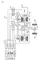
- FIG. 1 schematically illustrates the configuration of a hybrid vehicle equipped with a power output apparatus in one embodiment of the invention
- FIG. 2 shows one typical structure of a transmission included in the hybrid vehicle of the embodiment
- FIG. 3 is a flowchart showing a drive control routine executed by a hybrid electronic control unit included in the hybrid vehicle of the embodiment
- FIG. 4 is a flowchart showing the drive control routine executed by the hybrid electronic control unit included in the hybrid vehicle of the embodiment
- FIG. 5 shows one example of a torque demand setting map
- FIG. 6 shows an efficient operation curve of an engine to set a target rotation speed Ne* and a target torque Te*;
- FIG. 7 is an alignment chart showing torque-rotation speed dynamics of respective rotational elements of a power distribution integration mechanism included in the hybrid vehicle of the embodiment
- FIG. 8 is an alignment chart showing torque-rotation speed dynamics of the power distribution integration mechanism and the transmission
- FIG. 9 is a flowchart showing a modified drive control routine
- FIG. 10 is a flowchart showing the modified drive control routine
- FIG. 11 schematically illustrates the configuration of another hybrid vehicle in one modified example
- FIG. 12 schematically illustrates the configuration of still another hybrid vehicle in another modified example.
- FIG. 13 schematically illustrates the configuration of another hybrid vehicle in still another modified example.
- FIG. 1 schematically illustrates the configuration of a hybrid vehicle 20 equipped with a power output apparatus in one embodiment of the invention.
- the hybrid vehicle 20 of the embodiment includes an engine 22 , a three shaft-type power distribution integration mechanism 30 that is linked to a crankshaft 26 or an output shaft of the engine 22 via a damper 28 , a motor MG 1 that is linked to the power distribution integration mechanism 30 and has power generation capability, a motor MG 2 that is linked to the power distribution integration mechanism 30 via a transmission 60 , and a hybrid electronic control unit 70 that controls the whole operations of the hybrid vehicle 20 .
- the engine 22 is an internal combustion engine that uses a hydrocarbon fuel, such as gasoline or light oil, to output power.
- An engine electronic control unit (hereafter referred to as engine ECU) 24 receives signals from diverse sensors that detect operating conditions of the engine 22 , and takes charge of operation control of the engine 22 , for example, fuel injection control, ignition control, and intake air flow regulation.
- the engine ECU 24 communicates with the hybrid electronic control unit 70 to control operations of the engine 22 in response to control signals transmitted from the hybrid electronic control unit 70 while outputting data relating to the operating conditions of the engine 22 to the hybrid electronic control unit 70 according to the requirements.
- the power distribution and integration mechanism 30 has a sun gear 31 that is an external gear, a ring gear 32 that is an internal gear and is arranged concentrically with the sun gear 31 , multiple pinion gears 33 that engage with the sun gear 31 and with the ring gear 32 , and a carrier 34 that holds the multiple pinion gears 33 in such a manner as to allow free revolution thereof and free rotation thereof on the respective axes.
- the power distribution and integration mechanism 30 is constructed as a planetary gear mechanism that allows for differential motions of the sun gear 31 , the ring gear 32 , and the carrier 34 as rotational elements.
- the carrier 34 , the sun gear 31 , and the ring gear 32 in the power distribution and integration mechanism 30 are respectively coupled with the crankshaft 26 of the engine 22 , the motor MG 1 , and the reduction gear 35 via ring gear shaft 32 a .
- the motor MG 1 functions as a generator
- the power output from the engine 22 and input through the carrier 34 is distributed into the sun gear 31 and the ring gear 32 according to the gear ratio.
- the motor MG 1 functions as a motor
- the power output from the engine 22 and input through the carrier 34 is combined with the power output from the motor MG 1 and input through the sun gear 31 and the composite power is output to the ring gear 32 .
- the power output to the ring gear 32 is thus finally transmitted to the driving wheels 39 a and 39 b via the gear mechanism 37 , and the differential gear 38 from ring gear shaft 32 a.
- Both the motors MG 1 and MG 2 are known synchronous motor generators that are driven as a generator and as a motor.
- the motors MG 1 and MG 2 transmit electric power to and from a battery 50 via inverters 41 and 42 .
- Power lines 54 that connect the inverters 41 and 42 with the battery 50 are constructed as a positive electrode bus line and a negative electrode bus line shared by the inverters 41 and 42 . This arrangement enables the electric power generated by one of the motors MG 1 and MG 2 to be consumed by the other motor.
- the battery 50 is charged with a surplus of the electric power generated by the motor MG 1 or MG 2 and is discharged to supplement an insufficiency of the electric power.
- motor ECU 40 When the power balance is attained between the motors MG 1 and MG 2 , the battery 50 is neither charged nor discharged. Operations of both the motors MG 1 and MG 2 are controlled by a motor electronic control unit (hereafter referred to as motor ECU) 40 .
- the motor ECU 40 receives diverse signals required for controlling the operations of the motors MG 1 and MG 2 , for example, signals from rotational position detection sensors 43 and 44 that detect the rotational positions of rotors in the motors MG 1 and MG 2 and phase currents applied to the motors MG 1 and MG 2 and measured by current sensors (not shown).
- the motor ECU 40 outputs switching control signals to the inverters 41 and 42 .
- the motor ECU 40 executes a rotation speed computation routine (not shown) to calculate rotation speeds Nm 1 and Nm 2 of the respective rotors in the motors MG 1 and MG 2 from the input signals of the rotational position detection sensors 43 and 44 .
- the motor ECU 40 communicates with the hybrid electronic control unit 70 to control operations of the motors MG 1 and MG 2 in response to control signals transmitted from the hybrid electronic control unit 70 while outputting data relating to the operating conditions of the motors MG 1 and MG 2 to the hybrid electronic control unit 70 according to the requirements.
- the transmission 60 is designed to connect and disconnect a rotating shaft 48 of the motor MG 2 with and from the ring gear shaft 32 a . In the connection state, the transmission 60 reduces the rotation speed of the rotating shaft 48 of the motor MG 2 at two different reduction gear ratios and transmits the reduced rotation speed to the ring gear shaft 32 a .
- One typical structure of the transmission 60 is shown in FIG. 2 .
- the transmission 60 shown in FIG. 2 has a double-pinion planetary gear mechanism 60 a , a single-pinion planetary gear mechanism 60 b , and two brakes B 1 and B 2 .
- the double-pinion planetary gear mechanism 60 a includes a sun gear 61 as an external gear, a ring gear 62 as an internal gear arranged concentrically with the sun gear 61 , multiple first pinion gears 63 a engaging with the sun gear 61 , multiple second pinion gears 63 b engaging with the multiple first pinion gears 63 a and with the ring gear 62 , and a carrier 64 coupling the multiple first pinion gears 63 a to the multiple second pinion gears 63 b to allow both their revolutions and their rotations on their axes.
- the engagement and the release of the brake B 1 stop and allow the rotation of the sun gear 61 .
- the single-pinion planetary gear mechanism 60 b includes a sun gear 65 as an external gear, a ring gear 66 as an internal gear arranged concentrically with the sun gear 65 , multiple pinion gears 67 engaging with the sun gear 65 and with the ring gear 66 , and a carrier 68 holding the multiple pinion gears 67 to allow both their revolutions and their rotations on their axes.
- the sun gear 65 and the carrier 68 are respectively connected to the rotating shaft 48 of the motor MG 2 and to the ring gear shaft 32 a .
- the engagement and the release of the brake B 2 stop and allow the rotation of the ring gear 66 .
- the double-pinion planetary gear mechanism 60 a and the single-pinion planetary gear mechanism 60 b are coupled with each other via linkage of the respective ring gears 62 and 66 and linkage of the respective carriers 64 and 68 .
- the combination of the released brakes B 1 and B 2 disconnects the rotating shaft 48 of the motor MG 2 from the ring gear shaft 32 a .
- the combination of the released brake B 1 and the engaged brake B 2 reduces the rotation of the rotating shaft 48 of the motor MG 2 at a relatively high reduction gear ratio and transmits the reduced rotation to the ring gear shaft 32 a . This state is expressed as Lo gear position.
- the combination of the engaged brake B 1 and the released brake B 2 reduces the rotation of the rotating shaft 48 of the motor MG 2 at a relatively low reduction gear ratio and transmits the reduced rotation to the ring gear shaft 32 a .
- This state is expressed as Hi gear position.
- the combination of the engaged brakes B 1 and B 2 prohibits the rotations of the rotating shaft 48 and the ring gear shaft 32 a .
- the brakes B 1 and B 2 are engaged and released by controlling hydraulic actuators (not shown) to regulate the hydraulic pressure levels applied to the respective brakes B 1 and B 2 .
- the battery 50 is under control of a battery electronic control unit (hereafter referred to as battery ECU) 52 .
- the battery ECU 52 receives diverse signals required for control of the battery 50 , for example, an inter-terminal voltage measured by a voltage sensor (not shown) disposed between terminals of the battery 50 , a charge-discharge current measured by a current sensor (not shown) attached to the power line 54 connected with the output terminal of the battery 50 , and a battery temperature Tb measured by a temperature sensor 51 attached to the battery 50 .
- the battery ECU 52 outputs data relating to the state of the battery 50 to the hybrid electronic control unit 70 via communication according to the requirements.
- the battery ECU 52 calculates a state of charge (SOC) of the battery 50 , based on the accumulated charge-discharge current measured by the current sensor, for control of the battery 50 .
- SOC state of charge
- the hybrid electronic control unit 70 is constructed as a microprocessor including a CPU 72 , a ROM 74 that stores processing programs, a RAM 76 that temporarily stores data, and a non-illustrated input-output port, and a non-illustrated communication port.
- the hybrid electronic control unit 70 receives various inputs via the input port: an ignition signal from an ignition switch 80 , a gearshift position SP from a gearshift position sensor 82 that detects the current position of a gearshift lever 81 , an accelerator opening Acc from an accelerator pedal position sensor 84 that measures a step-on amount of an accelerator pedal 83 , a brake pedal position BP from a brake pedal position sensor 86 that measures a step-on amount of a brake pedal 85 , and a vehicle speed V from a vehicle speed sensor 88 .
- the hybrid electronic control unit 70 outputs, via its output port, driving signals to the hydraulic actuators (not shown) for the brakes B 1 and B 2 included in the transmission 60 .
- the hybrid electronic control unit 70 communicates with the engine ECU 24 , the motor ECU 40 , and the battery ECU 52 via the communication port to transmit diverse control signals and data to and from the engine ECU 24 , the motor ECU 40 , and the battery ECU 52 , as mentioned previously.
- the hybrid vehicle 20 of the embodiment thus constructed calculates a torque demand to be output to the ring gear shaft 32 a functioning as the drive shaft, based on observed values of a vehicle speed V and an accelerator opening Acc, which corresponds to a driver's step-on amount of an accelerator pedal 83 .
- the engine 22 and the motors MG 1 and MG 2 are subjected to operation control to output a required level of power corresponding to the calculated torque demand to the ring gear shaft 32 a .
- the operation control of the engine 22 and the motors MG 1 and MG 2 selectively effectuates one of a torque conversion drive mode, a charge-discharge drive mode, and a motor drive mode.
- the torque conversion drive mode controls the operations of the engine 22 to output a quantity of power equivalent to the required level of power, while driving and controlling the motors MG 1 and MG 2 to cause all the power output from the engine 22 to be subjected to torque conversion by means of the power distribution integration mechanism 30 and the motors MG 1 and MG 2 and output to the ring gear shaft 32 a .
- the charge-discharge drive mode controls the operations of the engine 22 to output a quantity of power equivalent to the sum of the required level of power and a quantity of electric power consumed by charging the battery 50 or supplied by discharging the battery 50 , while driving and controlling the motors MG 1 and MG 2 to cause all or part of the power output from the engine 22 equivalent to the required level of power to be subjected to torque conversion by means of the power distribution integration mechanism 30 and the motors MG 1 and MG 2 and output to the ring gear shaft 32 a , simultaneously with charge or discharge of the battery 50 .
- the motor drive mode stops the operations of the engine 22 and drives and controls the motor MG 2 to output a quantity of power equivalent to the required level of power to the ring gear shaft 32 a.
- FIGS. 3 and 4 are flowcharts showing a drive control routine executed by the hybrid electronic control unit 70 mounted on the hybrid vehicle 20 of the embodiment. This drive control routine is carried out repeatedly at preset time intervals, for example, at every several msec.
- the CPU 72 of the hybrid electronic control unit 70 first inputs various data required for control, that is, the accelerator opening Acc from the accelerator pedal position sensor 84 , the vehicle speed V from the vehicle speed sensor 88 , rotation speeds Nm 1 and Nm 2 of the motors MG 1 and MG 2 , a charge-discharge power demand Pb* to be charged into or discharged from the battery 50 , an output limit Wout of the battery 50 , and a gear position of the transmission 60 (step S 100 ).
- various data required for control that is, the accelerator opening Acc from the accelerator pedal position sensor 84 , the vehicle speed V from the vehicle speed sensor 88 , rotation speeds Nm 1 and Nm 2 of the motors MG 1 and MG 2 , a charge-discharge power demand Pb* to be charged into or discharged from the battery 50 , an output limit Wout of the battery 50 , and a gear position of the transmission 60 (step S 100 ).
- the rotation speeds Nm 1 and Nm 2 of the motors MG 1 and MG 2 are computed from the rotational positions of the respective rotors in the motors MG 1 and MG 2 detected by the rotational position detection sensors 43 and 44 and are received from the motor ECU 40 by communication.
- the charge-discharge power demand Pb* is set according to the current state of charge SOC of the battery 50 and is received from the battery ECU 52 by communication.
- the output limit Wout of the battery 50 is set based on the measured temperature Tb and the observed state of charge SOC of the battery 50 and is received from the battery ECU 52 by communication.
- the gear position of the transmission 60 is either the Lo gear position or the Hi gear position, which is specified by a reduction gear ratio Gr of the transmission 60 .
- the reduction ratio Gr of the transmission 60 is calculated by dividing a rotation speed Nm 2 of the motor MG 2 by a rotation speed Nr of the ring gear shaft 32 a .
- the rotation speed Nr of the ring gear shaft 32 a is obtained by multiplying the vehicle speed V by a preset conversion factor k.
- the CPU 72 sets a torque demand Tr* to be output to the ring gear shaft 32 a or the drive shaft and an engine power demand Pe* required for the engine 22 , based on the input accelerator opening Acc and the input vehicle speed V (step S 110 )
- a concrete procedure of setting the torque demand Tr* in this embodiment stores in advance variations in torque demand Tr* against the accelerator opening Acc and the vehicle speed V as a torque demand setting map in the ROM 74 and reads the torque demand Tr* corresponding to the given accelerator opening Acc and the given vehicle speed V from this torque demand setting map.
- One example of the torque demand setting map is shown in FIG. 5 .
- the engine power demand Pe* is calculated as the sum of the product of the torque demand Tr* and the rotation speed Nr of the ring gear shaft 32 a , the charge-discharge power demand Pb* to be charged into or discharged from the battery 50 , and a potential loss.
- the CPU 72 identifies the input gear position of the transmission 60 (step S 120 ) and determines whether a gearshift request of the transmission 60 is output in the Lo gear position of the transmission 60 (step S 130 ).
- the gearshift request of the transmission 60 is output at a specific timing depending upon the torque demand Tr* and the vehicle speed V.
- the engine power demand Pe* is compared with a preset reference power level Pref (step S 140 )
- the reference power level Pref is used as a criterion for determining whether the operation of the engine 22 is to be stopped, and is set to or around a lower limit of efficient power output of the engine 22 in this embodiment.
- the CPU 72 starts the engine 22 (step S 160 ) and sets a target rotation speed Ne* and a target torque Te* of the engine 22 corresponding to the engine power demand Pe* (step S 170 ).
- the target rotation speed Ne* and the target torque Te* of the engine 22 are determined according to an efficient operation curve of ensuring efficient operations of the engine 22 and the engine power demand Pe*.
- FIG. 6 shows an efficient operation curve of the engine 22 to set the target rotation speed Ne* and the target torque Te*.
- FIG. 7 is an alignment chart showing torque-rotation speed dynamics of the respective rotational elements included in the power distribution integration mechanism 30 .
- the left axis ‘S’ represents the rotation speed of the sun gear 31 that is equivalent to the rotation speed Nm 1 of the motor MG 1 .
- the middle axis ‘C’ represents the rotation speed of the carrier 34 that is equivalent to the rotation speed Ne of the engine 22 .
- the right axis ‘R’ represents the rotation speed Nr of the ring gear 32 (ring gear shaft 32 a ).
- the target rotation speed Nm 1 * of the motor MG 1 is readily introduced from the relation of the rotation speed in this alignment chart.
- Equation (2) is a relational expression of feedback control to drive and rotate the motor MG 1 at the target rotation speed Nm 1 *.
- ‘k 1 ’ in the second term and ‘k 2 ’ in the third term on the right side respectively denote a gain of the proportional and a gain of the integral term.
- the CPU 72 calculates an upper torque restriction Tmax as a maximum possible torque output from the motor MG 2 according to Equation (3) given below (step S 190 ).
- T max ( W out ⁇ Tm 1 * ⁇ Nm 1)/ Nm 2
- Equation (4) is readily led from the alignment chart of FIG. 7 .
- the CPU 72 sends the target rotation speed Ne* and the target torque Te* of the engine 22 to the engine ECU 24 and the torque commands Tm 1 * and Tm 2 * of the motors MG 1 and MG 2 to the motor ECU 40 (step S 220 ), and then exits from this drive control routine.
- the engine ECU 24 executes fuel injection control and ignition control to drive the engine 22 at the specified drive point of the target rotation speed Ne* and the target torque Te*.
- the engine ECU 24 starts the engine 22 and executes fuel injection control and ignition control to drive the engine 22 at the specified drive point of the target rotation speed Ne* and the target torque Te*.
- the motor ECU 40 receives the torque commands Tm 1 * and Tm 2 * and executes switching control of the switching elements included in the respective inverters 41 and 42 to drive the motor MG 1 with the torque command Tm 1 * and the motor MG 2 with the torque command Tm 2 *.
- the CPU 72 determines the requirement for a stop of the engine 22 and sets the value ‘0’ to both the target rotation speed Ne* and the target torque Te* to stop the engine 22 (step S 230 ). The CPU 72 subsequently sets the value ‘0’ to the torque command Tm 1 * of the motor MG 1 (step S 240 ) and sets the torque command Tm 2 * of the motor MG 2 (steps S 190 to S 210 ).
- the CPU 72 sends the target rotation speed Ne* and the target torque Te* of the engine 22 to the engine ECU 24 and the torque commands Tm 1 * and Tm 2 * of the motors MG 1 and MG 2 to the motor ECU 40 (step S 220 ), and exits from this drive control routine.
- the engine ECU 24 stops the operation of the engine 22 .
- the engine ECU 24 keeps the engine 22 at stop.
- the CPU 72 determines whether the engine 22 is in operation (step S 250 ) in the drive control routine of FIG. 4 .
- the CPU 72 gives a start command of the change speed process (step S 270 ) and sets the target rotation speed Ne* and the target torque Te* of the engine 22 to drive the engine 22 at an efficient drive point corresponding to the engine power demand Pe* (step S 290 ).
- the CPU 72 then executes the processing of and after step S 180 in the drive control routine of FIG. 3 .
- the change speed process drives and controls a hydraulic actuator (not shown) to change over the gear position of the transmission 60 from the combination of the released brake B 1 and the engaged brake B 2 to the combination of the engaged brake B 1 and the released brake B 2 .
- the CPU 72 starts the engine 22 (step S 280 ) and executes the processing of and after step S 290 .
- the start of the engine 22 leads to an affirmative answer at step S 250 .
- step S 260 When the change speed process of changing over the gear position of the transmission 60 has not yet started (step S 260 ), the CPU 72 gives the start command of the change speed process (step S 270 ) and executes the processing of and after step S 290 .
- the drive control routine executes the change speed process of changing over the gear position of the transmission 60 , while keeping the engine 22 in operation.
- the drive control routine starts the engine 22 and then executes the change speed process of changing over the gear position of the transmission 60 . This drive control is ascribed to the following reason. FIG.
- the axis ‘S’ represents the rotation speed of the sun gear 31 in the power distribution integration mechanism 30 that is equivalent to the rotation speed Nm 1 of the motor MG 1 .
- the axis ‘C’ represents the rotation speed of the carrier 34 in the power distribution integration mechanism 30 that is equivalent to the rotation speed Ne of the engine 22 .
- the axis ‘R’, ‘C 1 ’, and ‘C 2 ’ represents the rotation speed of the ring gear 32 (ring gear shaft 32 a ) in the power distribution integration mechanism 30 and the rotation speeds of the carriers 64 and 68 in the transmission 60 .
- the axis ‘S 2 ’ represents the rotation speed of the sun gear 65 in the transmission 60 that is equivalent to the rotation speed Nm 2 of the motor MG 2 .
- the axis ‘R 1 ’ and ‘R 2 ’ represents the rotation speeds of the ring gears 62 and 66 in the transmission 60 .
- the axis ‘S 1 ’ represents the rotation speed of the sun gear 61 in the transmission 60 .
- the change speed process changes over the gear position of the transmission 60 from the Lo gear position (shown by the solid line) to the Hi gear position (shown by the broken line). In this change speed process, the brake B 1 is changed from the released position through friction engagement to the engaged position, while the brake B 2 is changed from the engaged position to the released position.
- the greater output torque of the motor MG 2 causes the more significant shock on the ring gear shaft 32 a or the drive shaft in the gear change of the transmission 60 . It is thus desirable to minimize the output torque of the motor MG 2 .
- the output torque of the motor MG 2 is defined as division of the difference between the torque demand Tr* and a direct transmission torque Ter from the engine 22 by the reduction gear ratio Gr of the transmission 60 .
- the output torque of the motor MG 2 is defined as division of the torque demand Tr* by the reduction gear ratio Gr of the transmission 60 .
- the drive control routine executes the change speed process of changing over the gear position of the transmission 60 while keeping the engine 22 in operation.
- the drive control routine starts the engine 22 and then executes the change speed process of changing over the gear position of the transmission 60 .
- Such drive control effectively reduces the potential shock in the gear change of the transmission 60 .
- the gear position of the transmission 60 is changed over to the Hi gear position and the gearshift request of the transmission 60 is cancelled.
- step S 120 the CPU 72 determines whether a gearshift request of the transmission 60 is output (step S 300 ).
- the CPU 72 sets the target rotation speed Ne* and the target torque Te* of the engine 22 to drive the engine 22 under load at an efficient drive point corresponding to the engine power demand Pe* (step S 330 ) and sets the torque commands Tm 1 * and Tm 2 * of the motors MG 1 and MG 2 (steps S 180 to S 210 ).
- the CPU 72 sends the target rotation speed Ne* and the target torque Te* of the engine 22 to the engine ECU 24 and the torque commands Tm 1 * and Tm 2 * of the motors MG 1 and MG 2 to the motor ECU 40 (step S 220 ), and exits from this drive control routine.
- the drive control keeps the engine 22 in load operation, regardless of the magnitude of the engine power demand Pe*. This drive control is ascribed to the following reason.
- the reduction gear ratio Gr of the transmission 60 in the Hi gear position is smaller than the reduction gear ratio Gr in the Lo gear position.
- the maximum torque limit (Tm 2 * ⁇ Gr) applied to the ring gear shaft 32 a in the Hi gear position is accordingly lower than the maximum torque limit in the Lo gear position.
- the drive control routine starts the engine 22 and then controls the engine 22 and the motor MG 2 to output the required driving force to the ring gear shaft 32 a . This may cause a poor response to the driver's demand.
- the continuous load operation of the engine 22 in the Hi gear position of the transmission 60 enables the required driving force to be quickly output to the ring gear shaft 32 a . This is why the engine 22 is kept in load operation in the Hi gear position of the transmission 60 .
- step S 300 In response to output of a gearshift request of the transmission 60 at step S 300 , that is, in response to output of a command for changing over the gear position of the transmission 60 from the Hi gear position to the Lo gear position, when a change speed process of changing over the gear position of the transmission 60 has not yet started (step S 310 ), the CPU 72 gives a start command of the change speed process (step S 320 ) and executes the processing of and after step S 330 .
- the change speed process drives and controls a hydraulic actuator (not shown) to change over the gear position of the transmission 60 from the combination of the engaged brake B 1 and the released brake B 2 to the combination of the released brake B 1 and the engaged brake B 2 .
- the gearshift request of the transmission 60 is output in the continuous operation of the engine 22 .
- the drive control routine thus starts the change speed process to change over the gear position of the transmission 60 , while keeping the engine 22 in operation. The reason of such drive control is described previously.
- the engine 22 in the Lo gear position of the transmission 60 , the engine 22 is driven and controlled to be operated intermittently corresponding to the engine power demand Pe* and ensure output of the required driving force to the ring gear shaft 32 a or the drive shaft.
- the engine 22 In the Hi gear position of the transmission 60 , the engine 22 is driven and controlled to continue the load operation and ensure output of the required driving force to the ring gear shaft 32 a or the drive shaft.
- the drive control of the embodiment enables quicker output of the required driving force to the drive shaft, compared with the output of the driving force from the operation stop state of the engine 22 .
- the intermittent operation of the engine 22 in the Lo gear position of the transmission 60 desirably improves the energy efficiency.
- the drive control in response to output of a gearshift request of the transmission 60 in the operation state of the engine 22 , performs the change speed process of changing over the gear position of the transmission 60 while keeping the engine 22 in operation.
- the drive control starts the engine 22 and then performs the change speed process of changing over the gear position of the transmission 60 .
- Such drive control desirably decreases the output torque of the motor MG 2 , compared with the torque output in the operation stop state of the engine 22 , and thereby effectively reduces the potential shock in the gear change of the transmission 60 .
- the drive control routine sets the target rotation speed Ne* and the target torque Te* of the engine 22 to enable the load operation of the engine 22 at the efficient drive point corresponding to the engine power demand Pe* at step S 330 in the flowchart of FIG. 3 .
- One modified drive control routine may compare the engine power demand Pe* with a preset reference power level Pref in the Hi gear position of the transmission 60 . When the engine power demand Pe* is greater than the preset reference power level Pref, the modified drive control routine sets the target rotation speed Ne* and the target torque Te* of the engine 22 , in the same manner as step S 170 in the flowchart of FIG. 3 . When the engine power demand Pe* is not greater than the preset reference power level Pref, on the other hand, the modified drive control routine sets a value ‘0’ to the target torque Te* of the engine 22 and drives the engine 22 at idle.
- the engine 22 is operated intermittently or is driven continuously according to the gear position of the transmission 60 and the presence or the absence of a gearshift request.
- One possible modification may prohibit the operation stop of the engine 22 under a preset condition that depends upon the gear position of the transmission 60 and the presence or the absence of a gearshift request, for example, under the condition of the Hi gear position of the transmission 60 .
- a drive control routine of this modification is shown in the flowcharts of FIGS. 9 and 10 .
- This modified drive control routine first inputs various data required for control, that is, the accelerator opening Acc, the vehicle speed V, the rotation speeds Nm 1 and Nm 2 of the motors MG 1 and MG 2 , and the output limit Wout and the charge-discharge power demand Pb* of the battery 50 like the input at step S 100 in the drive control routine of FIGS. 3 and 4 , as well as a first operation stop prohibition judgment flag F 1 instead of the gear position of the transmission 60 (step S 400 ).
- the first operation stop prohibition judgment flag F 1 is used to determine whether the operation stop of the engine 22 is prohibited.
- the first operation stop prohibition judgment flag F 1 is set equal to 0 in the Lo gear position of the transmission 60 , whereas being set equal to 1 in the Hi gear position of the transmission 60 .
- the modified drive control routine subsequently sets the torque demand Tr* and the engine power demand Pe* (step S 110 ) and determines whether the first operation stop prohibition judgment flag F 1 is equal to 0 (step S 410 ).
- the first operation stop prohibition judgment flag F 1 is equal to 1, that is, in the Hi gear position of the transmission 60 , it is determined that the operation stop of the engine 22 is prohibited.
- the modified drive control routine then executes the processing of and after step S 300 like the drive control routine of FIGS. 3 and 4 .
- the modified drive control routine determines whether a second operation stop prohibition judgment flag F 2 is equal to 0 (step S 420 ).
- the second operation stop prohibition judgment flag F 2 is set in a previous cycle of this modified drive control routine and is used to determine whether the operation stop of the engine 22 is prohibited like the first operation stop prohibition judgment flag F 1 .
- the modified drive control routine determines whether a gearshift request of the transmission 60 is output (step S 130 ).
- no gearshift request of the transmission 60 is output in the Lo gear position of the transmission 60 (step S 130 )
- the modified drive control routine accordingly sets the value ‘0’ to the second operation stop prohibition judgment flag F 2 (step S 430 ) and executes the processing of and after step S 140 .
- the modified drive control routine determines whether the engine 22 is in operation (step S 250 ). In the operation state of the engine 22 , the modified drive control routine sets the value ‘1’ to the second operation stop prohibition judgment flag F 2 (step S 440 ) and executes the processing of and after step S 270 . In the operation stop state of the engine 22 , the modified drive control routine sets the value ‘0’ to the second operation stop prohibition judgment flag F 2 (step S 450 ) and starts the engine 22 (step S 280 ).
- the modified drive control routine sets the value ‘1’ to the second operation stop prohibition judgment flag F 2 (step S 440 ) and executes the processing of and after step S 270 .
- Setting the value ‘1’ to the second operation stop prohibition judgment flag F 2 gives a negative answer at step S 420 in a next cycle of the drive control routine and prohibits the operation stop of the engine 22 .
- the gear position of the transmission 60 is changed over to the Hi gear position, which sets the value ‘1’ to the first operation stop prohibition judgment flag F 1 . This setting gives a negative answer at step S 410 and prohibits the operation stop of the engine 22 .
- the transmission 60 has the two different speeds, that is, the Hi gear position and the Lo gear position.
- the transmission may have three or more different speeds or may be constructed as a continuously variable transmission.
- the reduction gear ratio is not greater than a preset reference level, which is less than a maximum possible reduction gear ratio
- the engine 22 is driven continuously.
- the drive control changes the reduction gear ratio of the transmission while keeping the engine 22 in operation.
- the drive control starts the engine 22 and then changes the reduction gear ratio of the transmission.
- the power of the motor MG 2 is converted by the gear change in the transmission 60 and is output to the ring gear shaft 32 a or the drive shaft.
- the technique of the invention is, however, not restricted to this configuration but may be adopted in a hybrid vehicle 120 of a modified configuration shown in FIG. 11 , where the power of the motor MG 2 is converted by the gear change in the transmission 60 and is transmitted to a different axle (an axle linked to wheels 39 c and 39 d ) from the axle connecting with the ring gear shaft 32 a (the axle linked to the drive wheels 39 a and 39 b ).
- the power of the engine 22 is output via the power distribution integration mechanism 30 to the ring gear shaft 32 a or the drive shaft linked to the drive wheels 39 a and 39 b .
- the technique of the invention is applicable to a hybrid vehicle 220 of another modified example as shown in FIG. 12 .
- the hybrid vehicle 220 of this modified configuration includes a pair-rotor motor 230 that includes an inner rotor 232 linked to the crankshaft 26 of the engine 22 and an outer rotor 234 connected to the drive shaft to output power to the drive wheels 39 a and 39 b .
- the pair-rotor motor 230 transmits part of the output power of the engine 22 to the drive shaft, while converting residual part of the output power into electric power.
- the power of the engine 22 is output via the power distribution integration mechanism 30 to the ring gear shaft 32 a or the drive shaft.
- the technique of the invention is also applicable to a hybrid vehicle 320 of still another modified example shown in FIG. 13 , where the power of the engine 22 is output to the drive shaft via another transmission 330 .
Abstract
Description
Nm1*=Ne*·(1+ρ)/ρ−Nr/ρ (1)
Tm1*=Previous Tm1*+k1(Nm1*−Nm1)+k2∫(Nm1*−Nm1)dt (2)
Equation (1) is a dynamic relational expression of the rotational elements included in the power
Tmax=(Wout−Tm1*·Nm1)/Nm2 (3)
A tentative motor torque Tm2tmp is calculated, as a torque to be output from the motor MG2, from the torque demand Tr*, the torque command Tm1* of the motor MG1, the gear ratio ρ of the power
Tm2tmp=(Tr*+Tm1*/ρ)/Gr (4)
A torque command Tm2* of the motor MG2 is set by limiting the calculated tentative motor torque Tm2 tmp to the upper torque restriction Tmax (step S210). Such setting of the torque command Tm2* of the motor MG2 restricts the torque demand Tr* to be output to the
Claims (21)
Applications Claiming Priority (2)
| Application Number | Priority Date | Filing Date | Title |
|---|---|---|---|
| JP2004358016A JP4190490B2 (en) | 2004-12-10 | 2004-12-10 | Power output device, automobile equipped with the same, control device for power output device, and control method for power output device |
| JP2004-358016 | 2004-12-10 |
Publications (2)
| Publication Number | Publication Date |
|---|---|
| US20060128523A1 US20060128523A1 (en) | 2006-06-15 |
| US7291093B2 true US7291093B2 (en) | 2007-11-06 |
Family
ID=36584752
Family Applications (1)
| Application Number | Title | Priority Date | Filing Date |
|---|---|---|---|
| US11/293,389 Active 2026-06-08 US7291093B2 (en) | 2004-12-10 | 2005-12-05 | Power output apparatus, control system for power output apparatus, and control method of power output apparatus |
Country Status (4)
| Country | Link |
|---|---|
| US (1) | US7291093B2 (en) |
| JP (1) | JP4190490B2 (en) |
| CN (1) | CN100431886C (en) |
| DE (1) | DE102005058956B4 (en) |
Cited By (6)
| Publication number | Priority date | Publication date | Assignee | Title |
|---|---|---|---|---|
| US20070185629A1 (en) * | 2004-07-15 | 2007-08-09 | Toyota Jidosha Kabushiki Kaisha | Hybrid vehicle, control method of hybrid vehicle, and power output apparatus |
| US20090204314A1 (en) * | 2008-02-13 | 2009-08-13 | Takanori Aoki | Power output apparatus, vehicle equipped with power output apparatus, driving system, and control method of power output apparatus |
| US20100256849A1 (en) * | 2009-04-02 | 2010-10-07 | Toyota Jidosha Kabushiki Kaisha | Power output apparatus, hybrid vehicle provided with power output apparatus, and control method of power output apparatus |
| US7832297B2 (en) | 2005-04-19 | 2010-11-16 | Hewatt Chris B | Method and apparatus for gyroscopic propulsion |
| US20110163727A1 (en) * | 2008-12-06 | 2011-07-07 | Bayerische Motoren Werke Aktiengesellschaft | Method for Regulating or Controlling the Charge State of an Electrical Energy Accumulator of a Hybrid Vehicle |
| US20120065828A1 (en) * | 2009-05-26 | 2012-03-15 | Toyota Jidosha Kabushiki Kaisha | Hybrid vehicle and travel mode setting method of hybrid vehicle |
Families Citing this family (16)
| Publication number | Priority date | Publication date | Assignee | Title |
|---|---|---|---|---|
| JP4203828B2 (en) * | 2006-07-10 | 2009-01-07 | アイシン・エィ・ダブリュ株式会社 | Hybrid drive device |
| JP4501925B2 (en) * | 2006-11-09 | 2010-07-14 | トヨタ自動車株式会社 | Control device for vehicle drive device |
| JP4222414B2 (en) * | 2006-12-04 | 2009-02-12 | トヨタ自動車株式会社 | POWER OUTPUT DEVICE, HYBRID VEHICLE HAVING THE SAME, AND METHOD FOR CONTROLLING POWER OUTPUT DEVICE |
| JP4100446B1 (en) | 2007-01-10 | 2008-06-11 | トヨタ自動車株式会社 | Hybrid drive apparatus and vehicle equipped with the same |
| US8062169B2 (en) * | 2007-04-30 | 2011-11-22 | Caterpillar Inc. | System for controlling a hybrid energy system |
| DE102007031605A1 (en) * | 2007-07-06 | 2009-01-22 | Dr. Ing. H.C. F. Porsche Aktiengesellschaft | hybrid vehicle |
| US8126624B2 (en) * | 2007-11-04 | 2012-02-28 | GM Global Technology Operations LLC | Method for selection of optimal mode and gear and input speed for preselect or tap up/down operation |
| US8121768B2 (en) * | 2007-11-05 | 2012-02-21 | GM Global Technology Operations LLC | Method for controlling a hybrid powertrain system based upon hydraulic pressure and clutch reactive torque capacity |
| US8195349B2 (en) * | 2007-11-07 | 2012-06-05 | GM Global Technology Operations LLC | Method for predicting a speed output of a hybrid powertrain system |
| JP2010184535A (en) * | 2009-02-10 | 2010-08-26 | Toyota Motor Corp | Hybrid vehicle |
| JP2011183946A (en) * | 2010-03-09 | 2011-09-22 | Aisin Aw Co Ltd | Hybrid driving device |
| DE102010017966A1 (en) * | 2010-04-23 | 2011-10-27 | Dr. Ing. H.C. F. Porsche Aktiengesellschaft | Vehicle with electric drive |
| DE102011056929A1 (en) * | 2011-12-22 | 2013-06-27 | Dr. Ing. H.C. F. Porsche Aktiengesellschaft | Powertrain of a purely electrically driven motor vehicle with two electric machines |
| JP6811630B2 (en) * | 2017-01-31 | 2021-01-13 | 株式会社エクセディ | Power transmission device with rotary electric machine |
| DE102017213604A1 (en) * | 2017-08-04 | 2019-02-07 | Ford Global Technologies, Llc | Method for operating a hybrid vehicle, and hybrid vehicle |
| CN113212412B (en) * | 2021-05-28 | 2022-05-10 | 恒大恒驰新能源汽车研究院(上海)有限公司 | Gear arbitration method, storage medium and electronic device for executing gear arbitration method |
Citations (7)
| Publication number | Priority date | Publication date | Assignee | Title |
|---|---|---|---|---|
| US4956972A (en) * | 1987-12-18 | 1990-09-18 | Honda Giken Kogyo Kabushiki Kaisha | Method of controlling speed reduction ratio for a continuously variable speed transmission |
| US5135443A (en) * | 1988-08-17 | 1992-08-04 | Zahnradfabrik Friedrichshafen Ag | Arrangement and method for operating a variable drive unit |
| US6335573B1 (en) * | 1999-08-02 | 2002-01-01 | Honda Giken Kogyo Kabushiki Kaisha | Engine control apparatus |
| JP2002225578A (en) | 2001-02-05 | 2002-08-14 | Toyota Motor Corp | Hybrid car |
| JP2004150334A (en) | 2002-10-30 | 2004-05-27 | Toyota Motor Corp | Hybrid automobile and its control method |
| JP2005207303A (en) | 2004-01-22 | 2005-08-04 | Toyota Motor Corp | Controller for hybrid vehicle |
| JP2005333713A (en) | 2004-05-19 | 2005-12-02 | Toyota Motor Corp | Motive power output device and automobile mounting it, and motive power transmission device, and control method for motive power output device |
Family Cites Families (9)
| Publication number | Priority date | Publication date | Assignee | Title |
|---|---|---|---|---|
| JP3668830B2 (en) * | 1998-08-28 | 2005-07-06 | トヨタ自動車株式会社 | Power transmission device and hybrid vehicle using the same |
| JP3861486B2 (en) * | 1998-12-18 | 2006-12-20 | トヨタ自動車株式会社 | Control device for hybrid vehicle |
| JP3703646B2 (en) * | 1999-02-12 | 2005-10-05 | 三菱電機株式会社 | Engine stop / start control device |
| JP3588673B2 (en) * | 1999-05-20 | 2004-11-17 | 日産自動車株式会社 | Idle stop vehicle |
| JP2000343964A (en) * | 1999-06-04 | 2000-12-12 | Toyota Motor Corp | Power output device and control thereof |
| JP3675240B2 (en) * | 1999-07-19 | 2005-07-27 | 日産自動車株式会社 | Vehicle tracking control device |
| JP3867521B2 (en) * | 2000-09-05 | 2007-01-10 | トヨタ自動車株式会社 | Electric oil pump control device |
| JP2004124827A (en) * | 2002-10-02 | 2004-04-22 | Toyota Motor Corp | Power output device and hybrid type power output device, and control method thereof, and hybrid vehicle |
| JP4066827B2 (en) * | 2003-02-03 | 2008-03-26 | マツダ株式会社 | Idle stop information sharing method, system, program, and computer-readable recording medium recording the program |
-
2004
- 2004-12-10 JP JP2004358016A patent/JP4190490B2/en not_active Expired - Fee Related
-
2005
- 2005-12-05 US US11/293,389 patent/US7291093B2/en active Active
- 2005-12-09 DE DE102005058956.1A patent/DE102005058956B4/en not_active Expired - Fee Related
- 2005-12-09 CN CNB2005101304005A patent/CN100431886C/en not_active Expired - Fee Related
Patent Citations (7)
| Publication number | Priority date | Publication date | Assignee | Title |
|---|---|---|---|---|
| US4956972A (en) * | 1987-12-18 | 1990-09-18 | Honda Giken Kogyo Kabushiki Kaisha | Method of controlling speed reduction ratio for a continuously variable speed transmission |
| US5135443A (en) * | 1988-08-17 | 1992-08-04 | Zahnradfabrik Friedrichshafen Ag | Arrangement and method for operating a variable drive unit |
| US6335573B1 (en) * | 1999-08-02 | 2002-01-01 | Honda Giken Kogyo Kabushiki Kaisha | Engine control apparatus |
| JP2002225578A (en) | 2001-02-05 | 2002-08-14 | Toyota Motor Corp | Hybrid car |
| JP2004150334A (en) | 2002-10-30 | 2004-05-27 | Toyota Motor Corp | Hybrid automobile and its control method |
| JP2005207303A (en) | 2004-01-22 | 2005-08-04 | Toyota Motor Corp | Controller for hybrid vehicle |
| JP2005333713A (en) | 2004-05-19 | 2005-12-02 | Toyota Motor Corp | Motive power output device and automobile mounting it, and motive power transmission device, and control method for motive power output device |
Cited By (11)
| Publication number | Priority date | Publication date | Assignee | Title |
|---|---|---|---|---|
| US20070185629A1 (en) * | 2004-07-15 | 2007-08-09 | Toyota Jidosha Kabushiki Kaisha | Hybrid vehicle, control method of hybrid vehicle, and power output apparatus |
| US7721833B2 (en) * | 2004-07-15 | 2010-05-25 | Toyota Jidosha Kabushiki Kaisha | Hybrid vehicle, control method of hybrid vehicle, and power output apparatus |
| US7832297B2 (en) | 2005-04-19 | 2010-11-16 | Hewatt Chris B | Method and apparatus for gyroscopic propulsion |
| US20090204314A1 (en) * | 2008-02-13 | 2009-08-13 | Takanori Aoki | Power output apparatus, vehicle equipped with power output apparatus, driving system, and control method of power output apparatus |
| US8050851B2 (en) * | 2008-02-13 | 2011-11-01 | Toyota Jidosha Kabushiki Kaisha | Power output apparatus, vehicle equipped with power output apparatus, driving system, and control method of power output apparatus |
| US20110163727A1 (en) * | 2008-12-06 | 2011-07-07 | Bayerische Motoren Werke Aktiengesellschaft | Method for Regulating or Controlling the Charge State of an Electrical Energy Accumulator of a Hybrid Vehicle |
| US8256548B2 (en) * | 2008-12-06 | 2012-09-04 | Bayerische Motoren Werke Aktiengesellschaft | Method for regulating or controlling the charge state of an electrical energy accumulator of a hybrid vehicle |
| US20100256849A1 (en) * | 2009-04-02 | 2010-10-07 | Toyota Jidosha Kabushiki Kaisha | Power output apparatus, hybrid vehicle provided with power output apparatus, and control method of power output apparatus |
| US8380376B2 (en) * | 2009-04-02 | 2013-02-19 | Toyota Jidosha Kabushiki Kaisha | Power output apparatus, hybrid vehicle provided with power output apparatus, and control method of power output apparatus |
| US20120065828A1 (en) * | 2009-05-26 | 2012-03-15 | Toyota Jidosha Kabushiki Kaisha | Hybrid vehicle and travel mode setting method of hybrid vehicle |
| US10315641B2 (en) * | 2009-05-26 | 2019-06-11 | Toyota Jidosha Kabushiki Kaisha | Hybrid vehicle and travel mode setting method of hybrid vehicle |
Also Published As
| Publication number | Publication date |
|---|---|
| CN1785728A (en) | 2006-06-14 |
| DE102005058956A1 (en) | 2006-07-06 |
| US20060128523A1 (en) | 2006-06-15 |
| DE102005058956B4 (en) | 2016-01-07 |
| CN100431886C (en) | 2008-11-12 |
| JP4190490B2 (en) | 2008-12-03 |
| JP2006161778A (en) | 2006-06-22 |
Similar Documents
| Publication | Publication Date | Title |
|---|---|---|
| US7291093B2 (en) | Power output apparatus, control system for power output apparatus, and control method of power output apparatus | |
| US8136617B2 (en) | Power output apparatus and hybrid vehicle equipped with the same | |
| US7555373B2 (en) | Hybrid vehicle and control method of hybrid vehicle | |
| US7575078B2 (en) | Vehicle and control method of vehicle | |
| US7562730B2 (en) | Hybrid vehicle and control method of hybrid vehicle | |
| US7559871B2 (en) | Power output apparatus, motor vehicle equipped with power output apparatus, and control method of power output apparatus | |
| US7532961B2 (en) | Power output apparatus, method of controlling the same, and automobile | |
| US7721833B2 (en) | Hybrid vehicle, control method of hybrid vehicle, and power output apparatus | |
| US7255662B2 (en) | Power output apparatus and hybrid vehicle | |
| US7736265B2 (en) | Power output apparatus | |
| US7632212B2 (en) | Hybrid vehicle and control method of the same | |
| US8123655B2 (en) | Power output apparatus, drive system, and control method of power output apparatus | |
| US8088035B2 (en) | Vehicle and control method of vehicle | |
| US20080109142A1 (en) | Power Output Apparatus, Motor Vehicle Equipped With Power Output Apparatus, And Control Method Of Power Output Apparatus | |
| US7062916B2 (en) | Power output apparatus and control method of the same | |
| US7108088B2 (en) | Hybrid vehicle and control method of hybrid vehicle | |
| US8249769B2 (en) | Vehicle and control method thereof | |
| US7431111B2 (en) | Hybrid power output apparatus and control method | |
| US7794356B2 (en) | Power output apparatus, control method thereof, vehicle equipped with power output apparatus, and driving system | |
| US20090062063A1 (en) | Vehicle, driving system, and control methods thereof | |
| US7270621B2 (en) | Moving body and control method of moving body | |
| US7729838B2 (en) | Vehicle and control method of the same | |
| US20070255463A1 (en) | Power Output Apparatus, Motor Vehicle Equipped with Power Output Apparatus, and Control Method of Power Output Apparatus | |
| US8002055B2 (en) | Power output apparatus, control method of power output apparatus, and vehicle equipped with power output apparatus | |
| US8612112B2 (en) | Vehicle and control method thereof |
Legal Events
| Date | Code | Title | Description |
|---|---|---|---|
| AS | Assignment |
Owner name: AISIN AW CO., LTD., JAPAN Free format text: ASSIGNMENT OF ASSIGNORS INTEREST;ASSIGNORS:YAMAMOTO, MASAYA;UEOKA, KIYOSHIRO;KAMICHI, KENSUKE;AND OTHERS;REEL/FRAME:017323/0969;SIGNING DATES FROM 20051116 TO 20051117 Owner name: TOYOTA JIDOSHA KABUSHIKI KAISHA, JAPAN Free format text: ASSIGNMENT OF ASSIGNORS INTEREST;ASSIGNORS:YAMAMOTO, MASAYA;UEOKA, KIYOSHIRO;KAMICHI, KENSUKE;AND OTHERS;REEL/FRAME:017323/0969;SIGNING DATES FROM 20051116 TO 20051117 |
|
| STCF | Information on status: patent grant |
Free format text: PATENTED CASE |
|
| FEPP | Fee payment procedure |
Free format text: PAYOR NUMBER ASSIGNED (ORIGINAL EVENT CODE: ASPN); ENTITY STATUS OF PATENT OWNER: LARGE ENTITY |
|
| FPAY | Fee payment |
Year of fee payment: 4 |
|
| FPAY | Fee payment |
Year of fee payment: 8 |
|
| MAFP | Maintenance fee payment |
Free format text: PAYMENT OF MAINTENANCE FEE, 12TH YEAR, LARGE ENTITY (ORIGINAL EVENT CODE: M1553); ENTITY STATUS OF PATENT OWNER: LARGE ENTITY Year of fee payment: 12 |