US7284956B2 - Methods and apparatus for controlling a continuous flow rotary blood pump - Google Patents
Methods and apparatus for controlling a continuous flow rotary blood pump Download PDFInfo
- Publication number
- US7284956B2 US7284956B2 US10/291,191 US29119102A US7284956B2 US 7284956 B2 US7284956 B2 US 7284956B2 US 29119102 A US29119102 A US 29119102A US 7284956 B2 US7284956 B2 US 7284956B2
- Authority
- US
- United States
- Prior art keywords
- pump
- rotational speed
- current
- accordance
- normal operating
- Prior art date
- Legal status (The legal status is an assumption and is not a legal conclusion. Google has not performed a legal analysis and makes no representation as to the accuracy of the status listed.)
- Expired - Fee Related, expires
Links
Images


Classifications
-
- F—MECHANICAL ENGINEERING; LIGHTING; HEATING; WEAPONS; BLASTING
- F04—POSITIVE - DISPLACEMENT MACHINES FOR LIQUIDS; PUMPS FOR LIQUIDS OR ELASTIC FLUIDS
- F04B—POSITIVE-DISPLACEMENT MACHINES FOR LIQUIDS; PUMPS
- F04B49/00—Control, e.g. of pump delivery, or pump pressure of, or safety measures for, machines, pumps, or pumping installations, not otherwise provided for, or of interest apart from, groups F04B1/00 - F04B47/00
- F04B49/06—Control using electricity
-
- A—HUMAN NECESSITIES
- A61—MEDICAL OR VETERINARY SCIENCE; HYGIENE
- A61M—DEVICES FOR INTRODUCING MEDIA INTO, OR ONTO, THE BODY; DEVICES FOR TRANSDUCING BODY MEDIA OR FOR TAKING MEDIA FROM THE BODY; DEVICES FOR PRODUCING OR ENDING SLEEP OR STUPOR
- A61M60/00—Blood pumps; Devices for mechanical circulatory actuation; Balloon pumps for circulatory assistance
- A61M60/10—Location thereof with respect to the patient's body
- A61M60/104—Extracorporeal pumps, i.e. the blood being pumped outside the patient's body
-
- A—HUMAN NECESSITIES
- A61—MEDICAL OR VETERINARY SCIENCE; HYGIENE
- A61M—DEVICES FOR INTRODUCING MEDIA INTO, OR ONTO, THE BODY; DEVICES FOR TRANSDUCING BODY MEDIA OR FOR TAKING MEDIA FROM THE BODY; DEVICES FOR PRODUCING OR ENDING SLEEP OR STUPOR
- A61M60/00—Blood pumps; Devices for mechanical circulatory actuation; Balloon pumps for circulatory assistance
- A61M60/10—Location thereof with respect to the patient's body
- A61M60/122—Implantable pumps or pumping devices, i.e. the blood being pumped inside the patient's body
- A61M60/165—Implantable pumps or pumping devices, i.e. the blood being pumped inside the patient's body implantable in, on, or around the heart
- A61M60/178—Implantable pumps or pumping devices, i.e. the blood being pumped inside the patient's body implantable in, on, or around the heart drawing blood from a ventricle and returning the blood to the arterial system via a cannula external to the ventricle, e.g. left or right ventricular assist devices
-
- A—HUMAN NECESSITIES
- A61—MEDICAL OR VETERINARY SCIENCE; HYGIENE
- A61M—DEVICES FOR INTRODUCING MEDIA INTO, OR ONTO, THE BODY; DEVICES FOR TRANSDUCING BODY MEDIA OR FOR TAKING MEDIA FROM THE BODY; DEVICES FOR PRODUCING OR ENDING SLEEP OR STUPOR
- A61M60/00—Blood pumps; Devices for mechanical circulatory actuation; Balloon pumps for circulatory assistance
- A61M60/20—Type thereof
- A61M60/205—Non-positive displacement blood pumps
- A61M60/216—Non-positive displacement blood pumps including a rotating member acting on the blood, e.g. impeller
- A61M60/226—Non-positive displacement blood pumps including a rotating member acting on the blood, e.g. impeller the blood flow through the rotating member having mainly radial components
- A61M60/232—Centrifugal pumps
-
- A—HUMAN NECESSITIES
- A61—MEDICAL OR VETERINARY SCIENCE; HYGIENE
- A61M—DEVICES FOR INTRODUCING MEDIA INTO, OR ONTO, THE BODY; DEVICES FOR TRANSDUCING BODY MEDIA OR FOR TAKING MEDIA FROM THE BODY; DEVICES FOR PRODUCING OR ENDING SLEEP OR STUPOR
- A61M60/00—Blood pumps; Devices for mechanical circulatory actuation; Balloon pumps for circulatory assistance
- A61M60/20—Type thereof
- A61M60/205—Non-positive displacement blood pumps
- A61M60/216—Non-positive displacement blood pumps including a rotating member acting on the blood, e.g. impeller
- A61M60/237—Non-positive displacement blood pumps including a rotating member acting on the blood, e.g. impeller the blood flow through the rotating member having mainly axial components, e.g. axial flow pumps
-
- A—HUMAN NECESSITIES
- A61—MEDICAL OR VETERINARY SCIENCE; HYGIENE
- A61M—DEVICES FOR INTRODUCING MEDIA INTO, OR ONTO, THE BODY; DEVICES FOR TRANSDUCING BODY MEDIA OR FOR TAKING MEDIA FROM THE BODY; DEVICES FOR PRODUCING OR ENDING SLEEP OR STUPOR
- A61M60/00—Blood pumps; Devices for mechanical circulatory actuation; Balloon pumps for circulatory assistance
- A61M60/40—Details relating to driving
- A61M60/403—Details relating to driving for non-positive displacement blood pumps
- A61M60/419—Details relating to driving for non-positive displacement blood pumps the force acting on the blood contacting member being permanent magnetic, e.g. from a rotating magnetic coupling between driving and driven magnets
-
- A—HUMAN NECESSITIES
- A61—MEDICAL OR VETERINARY SCIENCE; HYGIENE
- A61M—DEVICES FOR INTRODUCING MEDIA INTO, OR ONTO, THE BODY; DEVICES FOR TRANSDUCING BODY MEDIA OR FOR TAKING MEDIA FROM THE BODY; DEVICES FOR PRODUCING OR ENDING SLEEP OR STUPOR
- A61M60/00—Blood pumps; Devices for mechanical circulatory actuation; Balloon pumps for circulatory assistance
- A61M60/50—Details relating to control
- A61M60/508—Electronic control means, e.g. for feedback regulation
- A61M60/538—Regulation using real-time blood pump operational parameter data, e.g. motor current
- A61M60/546—Regulation using real-time blood pump operational parameter data, e.g. motor current of blood flow, e.g. by adapting rotor speed
-
- A—HUMAN NECESSITIES
- A61—MEDICAL OR VETERINARY SCIENCE; HYGIENE
- A61M—DEVICES FOR INTRODUCING MEDIA INTO, OR ONTO, THE BODY; DEVICES FOR TRANSDUCING BODY MEDIA OR FOR TAKING MEDIA FROM THE BODY; DEVICES FOR PRODUCING OR ENDING SLEEP OR STUPOR
- A61M60/00—Blood pumps; Devices for mechanical circulatory actuation; Balloon pumps for circulatory assistance
- A61M60/50—Details relating to control
- A61M60/508—Electronic control means, e.g. for feedback regulation
- A61M60/538—Regulation using real-time blood pump operational parameter data, e.g. motor current
- A61M60/554—Regulation using real-time blood pump operational parameter data, e.g. motor current of blood pressure
-
- F—MECHANICAL ENGINEERING; LIGHTING; HEATING; WEAPONS; BLASTING
- F04—POSITIVE - DISPLACEMENT MACHINES FOR LIQUIDS; PUMPS FOR LIQUIDS OR ELASTIC FLUIDS
- F04D—NON-POSITIVE-DISPLACEMENT PUMPS
- F04D15/00—Control, e.g. regulation, of pumps, pumping installations or systems
- F04D15/0066—Control, e.g. regulation, of pumps, pumping installations or systems by changing the speed, e.g. of the driving engine
-
- A—HUMAN NECESSITIES
- A61—MEDICAL OR VETERINARY SCIENCE; HYGIENE
- A61M—DEVICES FOR INTRODUCING MEDIA INTO, OR ONTO, THE BODY; DEVICES FOR TRANSDUCING BODY MEDIA OR FOR TAKING MEDIA FROM THE BODY; DEVICES FOR PRODUCING OR ENDING SLEEP OR STUPOR
- A61M2205/00—General characteristics of the apparatus
- A61M2205/33—Controlling, regulating or measuring
- A61M2205/3331—Pressure; Flow
- A61M2205/3334—Measuring or controlling the flow rate
-
- A—HUMAN NECESSITIES
- A61—MEDICAL OR VETERINARY SCIENCE; HYGIENE
- A61M—DEVICES FOR INTRODUCING MEDIA INTO, OR ONTO, THE BODY; DEVICES FOR TRANSDUCING BODY MEDIA OR FOR TAKING MEDIA FROM THE BODY; DEVICES FOR PRODUCING OR ENDING SLEEP OR STUPOR
- A61M60/00—Blood pumps; Devices for mechanical circulatory actuation; Balloon pumps for circulatory assistance
- A61M60/10—Location thereof with respect to the patient's body
- A61M60/122—Implantable pumps or pumping devices, i.e. the blood being pumped inside the patient's body
- A61M60/126—Implantable pumps or pumping devices, i.e. the blood being pumped inside the patient's body implantable via, into, inside, in line, branching on, or around a blood vessel
- A61M60/148—Implantable pumps or pumping devices, i.e. the blood being pumped inside the patient's body implantable via, into, inside, in line, branching on, or around a blood vessel in line with a blood vessel using resection or like techniques, e.g. permanent endovascular heart assist devices
-
- Y—GENERAL TAGGING OF NEW TECHNOLOGICAL DEVELOPMENTS; GENERAL TAGGING OF CROSS-SECTIONAL TECHNOLOGIES SPANNING OVER SEVERAL SECTIONS OF THE IPC; TECHNICAL SUBJECTS COVERED BY FORMER USPC CROSS-REFERENCE ART COLLECTIONS [XRACs] AND DIGESTS
- Y10—TECHNICAL SUBJECTS COVERED BY FORMER USPC
- Y10S—TECHNICAL SUBJECTS COVERED BY FORMER USPC CROSS-REFERENCE ART COLLECTIONS [XRACs] AND DIGESTS
- Y10S415/00—Rotary kinetic fluid motors or pumps
- Y10S415/90—Rotary blood pump
-
- Y—GENERAL TAGGING OF NEW TECHNOLOGICAL DEVELOPMENTS; GENERAL TAGGING OF CROSS-SECTIONAL TECHNOLOGIES SPANNING OVER SEVERAL SECTIONS OF THE IPC; TECHNICAL SUBJECTS COVERED BY FORMER USPC CROSS-REFERENCE ART COLLECTIONS [XRACs] AND DIGESTS
- Y10—TECHNICAL SUBJECTS COVERED BY FORMER USPC
- Y10S—TECHNICAL SUBJECTS COVERED BY FORMER USPC CROSS-REFERENCE ART COLLECTIONS [XRACs] AND DIGESTS
- Y10S417/00—Pumps
- Y10S417/90—Slurry pumps, e.g. concrete
Definitions
- the present invention relates to the field of rotary blood pumps for assisting a failing human heart. More specifically, the present invention relates to the control of continuous flow rotary blood pump which does not compete with the bodies autonomic system unless the pump flow is detected to be outside of a predetermined range.
- rotary blood pumps have been developed and are currently under development for use as heart assist devices. Compared to pulsatile pumps, rotary blood pumps have several advantages, including smaller size, higher efficiency, and a simpler design.
- LVAS left ventricular assist device
- rotary blood pumps may be used outside of a hospital environment, for example in nursing homes and home health care environments, it would be advantageous to provide an automated control system for controlling the rotary blood pump, without the need for human supervision and intervention. It would be advantageous for such a control system to operate the rotary blood pump automatically and effectively in response to any sudden changes in the operating conditions of the pump which deviate from a normal operating range.
- the present invention relates to a control system for a continuous flow rotary blood pump, such as a centrifugal pump or an axial flow pump.
- a normal operating range of the blood pump is established.
- the normal operating range may comprise a normal pump flow range and a normal pressure head range.
- a target rotational speed of the pump can then be set in accordance with the normal operating range.
- a current operating condition of the blood pump is determined.
- the current operating condition may comprise a current pump flow, a current pressure head, and a current rotational speed of the pump.
- the current operating condition can then be compared with the normal operating range.
- An appropriate control algorithm is then selected from a plurality of available control algorithms based on the comparison.
- the target rotational speed of the pump can then be adjusted using the selected control algorithm to maintain or recover the normal operating range.
- the rotary blood pump may be used as a left ventricular assist device or a right ventricular assist device.
- the blood pump may be an implantable device or an external device.
- Measurements of the current pump flow, the current pressure head, and the current rotational speed may be used to determine the current operating condition.
- the current pump flow, the current pressure head, and the current rotational speed may be measured by one or more sensors.
- sensors may be implantable sensors. Alternatively, such sensors may be external sensors.
- the normal operating range may be established by determining a target operating point for the target rotational speed of the pump, which provides a target pump flow and a target pressure head.
- the normal pump flow range may be within a 20% deviation from the target pump flow.
- the normal pressure head range may be within a 25% deviation from the target pressure head.
- a normal operating condition control algorithm is selected.
- the target rotational speed of the pump is maintained by applying proportional and derivative gain control to the pump.
- K p may be set to approximately 0.02 and K d may be set to approximately 0.05.
- a first abnormal operating condition control algorithm is selected. This algorithm decreases the target rotational speed until the normal operating range is recovered.
- the target rotational speed may be decremented by x rpm every t seconds until the normal operating range is recovered.
- the normal operating range may be recovered by, for example, decrementing the rotational speed by approximately 150 rpm every 5 seconds.
- the normal operating range may be recovered by, for example, decrementing the rotational speed by approximately 600 rpm every 5 seconds.
- a second abnormal operating condition control algorithm is selected. This algorithm increases the target rotational speed until the normal operating range is recovered. For example, the target rotational speed may be incremented by x rpm every t seconds until the normal operating range is recovered. For a centrifugal pump, research has shown that the normal operating range may be recovered by, for example, incrementing the rotational speed by approximately 150 rpm every 5 seconds. For an axial flow pump, research has shown that the normal operating range may be recovered by, for example, incrementing the rotational speed by approximately 600 rpm every 5 seconds.
- a suction condition control algorithm is selected. This algorithm causes the suction condition to be released by continuously decreasing the target rotational speed of the pump to obtain a pump flow free from suction and free from overpumping. Once the suction condition is released, the target rotational speed of the pump is gradually increased to recover the normal operating range.
- the target rotational speed When releasing the suction condition, the target rotational speed may be continuously decremented by x 1 rpm every t seconds. Once the suction condition is released, the target rotational speed may be continuously incremented by x 2 rpm every t seconds to recover the normal operating condition.
- the suction condition may be released when the rotational speed of the pump is decremented by approximately 150 rpm every 5 seconds (e.g., x 1 is approximately 150 rpm and t is approximately 5).
- the normal operating range can then be recovered by incrementing the rotational speed of the pump by approximately 50 rpm every 5 seconds (e.g., x 2 is approximately 50 rpm and t is approximately 5 seconds).
- the suction condition may be released when the rotational speed of the pump is decremented by approximately 600 rpm every 5 seconds (e.g., x 1 is approximately 600 rpm and t is approximately 5).
- the normal operating range can then be recovered by incrementing the rotational speed of the pump by approximately 200 rpm every 5 seconds (e.g., x 2 is approximately 200 rpm and t is approximately 5 seconds).
- the pump may comprise a centrifugal pump having magnets implanted in the pump impeller.
- One or more Hall sensors may be used to detect the position of the pump impeller using the well-known Hall effect.
- the Hall sensors may be used to detect vertical and/or horizontal movement of the pump impeller.
- the rpm of the impeller may be adjusted based on the position as detected by the Hall sensors in order to maintain the impeller position in one of a top contact position or a dynamic suspension position.
- the Hall sensors detect the impeller position is at or near a bottom contact position
- the rotary blood pump may comprise an axial flow pump.
- the axial flow pump may have one or more magnets implanted in the impeller.
- the impeller may be affected by the pulsation of the natural heart. For example, the impeller may be moved back and forth horizontally along the axis of the impeller suspension system. It is desirable to maintain the impeller in a position of dynamic suspension between the supporting structures in order prevent the formation of blood clots or thrombi. A gap between the impeller and the supporting structures of at least 100 microns is necessary to prevent the formation of thrombi.
- Such an anti-thrombogenic position (dynamic suspension position) may be equated with a normal operating condition of the pump.
- FIG. 1 shows a block diagram of an example embodiment of the invention
- FIG. 2 is a graphical illustration of operating conditions of an example implementation of the invention
- FIG. 3 shows a flowchart of an example embodiment of the invention
- FIG. 4 shows an example embodiment of a centrifugal pump with a Hall sensor in accordance with the invention
- FIG. 5 shows an example Hall sensor configuration for use with the invention
- FIG. 6 shows a graph of the impeller position versus rpm of the pump of FIG. 4 ;
- FIG. 7 shows an example model circulation loop used in testing of an embodiment of the invention
- FIG. 8 is a graphical illustration of the convergence response time of an a continuous flow blood pump in accordance with an example embodiment of the invention.
- FIG. 9 ( FIGS. 9( i )- 9 ( iv )) show experimental results for a model implementation of the invention when recovering from an abnormal condition
- FIG. 10 ( FIGS. 10( i )- 10 ( iv )) show experimental results for a model implementation of the invention when recovering from a suction condition
- FIG. 11 shows an example embodiment of an axial flow pump in accordance with the invention.
- the present invention provides control means for a rotary blood pump.
- the pump impeller In order to operate the pump as a durable anti-thrombogenic rotary blood pump, the pump impeller must be suspended dynamically by either hydraulic or magnetic means when implanted as a bypass pump for a failing heart.
- the rotary blood pump may comprise, for example, a centrifugal pump or an axial flow pump.
- the impeller For a centrifugal blood pump, dynamic suspension of the impeller is established when the impeller RPM is synchronized with the beating natural heart. Within a certain RPM range, the impeller achieves dynamic suspension. Typically, for a centrifugal blood pump, the impeller RPM range should be approximately 2,000 ⁇ 1,000 RPM and produce 4 L/min ⁇ 2 L/min pump flow. The impeller moves toward the top of the pump during the diastolic phase of the natural heart; whereas, during the systolic phase of the natural heart, the impeller moves toward the bottom of the pump. To maintain the dynamic suspension, a specified gap between the male and female bearings is required. Typically, the gap should measure more than 400 ⁇ .
- this gap is less than 400 ⁇ (typically, down to 80 ⁇ ), effective suspension of the impeller to prevent blood clot formation does not occur.
- stagnant blood areas inside the pump are reduced or eliminated cyclically (typically at around 100 beat/min).
- thrombogenic areas inside the blood pump are also eliminated.
- the swinging motion of the impeller In order to further accelerate the reduction of thrombogenic areas inside a blood pump whose inflow tube is not vertical or whose radius of the male (smaller) and female (larger) bearings are different, the swinging motion of the impeller must be generated and synchronized with the natural heart. Typically, this swinging motion of the impeller would be generated when the impeller is at the top contact mode inside of the blood pump.
- Dynamic suspension of the impeller of an axial flow blood pump is also possible under proper conditions.
- Dynamic suspension of the impeller should be synchronized with the beating natural heart so that the impeller moves back and forth horizontally along an axis of the impeller suspension system. Such impeller movements should prevent blood clot formations at the gap between the impeller and its forward-and-backward supporting structure.
- the gap required for this type of dynamic suspension should be greater than approximately 100 ⁇ .
- a centrifugal pump to eliminate blood clot formation inside an axial flow blood pump, it is imperative that the impeller movement be synchronized with the beating of the natural heart.
- an axial flow blood pump would be operated within the range of 10,000 ⁇ 4,000 RPM in order to generate clinically needed blood flow of 4 L/min ⁇ 2 L/min.
- the dynamic suspension of the impeller should be established within this RPM range such that a gap of at least 100 ⁇ between the impeller and the supporting structures is maintained during the back and forth movement of the impeller caused by the beating heart.
- a gap of greater than 100 ⁇ is preferred, but may vary depending on pump structure. For example, decoupling may occur due to too large of a gap for the axial flow pump structure.
- Suspension of the impeller may also be achieved magnetically. Regardless of the means of suspension, the back and forth movement of the impeller along an axis of the flow pump structure is required to achieve endurance and thrombus-free operation.
- a rotary blood pump 10 which has an established normal operating range.
- the normal operating range may comprise a normal pump flow range and a normal pressure head range.
- a motor driver 12 is provided to enable driving of the pump 10 at a target rotational speed in accordance with the normal operating range.
- a condition estimator 14 is provided to enable determination of a current operating condition of the blood pump 10 .
- the current operating condition may comprise a current pump flow, a current pressure head, and a current rotational speed of the pump.
- a processor 16 is provided to: (1) enable a comparison between the current operating condition and the normal operating range; and (2) enable the selection of an appropriate control algorithm from a plurality of available control algorithms 18 based on the comparison.
- a controller 20 enables adjustment of the target rotational speed of the pump using the selected control algorithm in order to maintain or recover the normal operating range.
- the rotary blood pump 10 may be used as a left ventricular assist device or a right ventricular assist device.
- the rotary blood pump 10 may be an implantable device or an external device.
- Measurements of the current pump flow and the current pressure head may be provided to the condition estimator 14 to determine the current operating condition.
- a measurement of the current rotational speed 24 may be provided to the controller 20 as feedback for use in maintaining the target rotational speed of the pump 10 .
- the current pump flow, the current pressure head, and the current rotational speed may be measured by one or more sensors.
- the one or more sensors may be implantable sensors. Those skilled in the art will appreciate that external sensors may also be used to implement the invention.
- the normal operating range may be established by determining a target operating point for the target rotational speed of the pump 10 , which provides a target pump flow and a target pressure head.
- the normal pump flow range may be set as a 20% deviation from the target pump flow.
- the normal pressure head range may be set as a 25% deviation from the target pressure head.
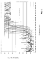
- FIG. 2 shows is a plot of pump flow versus pressurehead which illustrates an example of a normal operating range centered about a target operating point.
- the target operating point in the example shown in FIG. 2 is 100 mm Hg at 5 liters per minute.
- the normal pump flow range is within a 20% deviation from the target operating point pump flow or within the range of 4 to 6 liters per minute.
- the normal pressurehead is within a 25% deviation from the target operating point pressurehead or within the range of 75 to 125 mm Hg. Outside of the normal operating range an abnormal condition or a suction condition will be detected.
- the processor 16 selects a normal operating condition control algorithm.
- the controller 20 maintains the target rotational speed of the pump 10 by applying proportional and derivative gain control to the pump 10 , in accordance with the normal operating condition control algorithm.
- K p may be set to approximately 0.02 and K d may be set to approximately 0.05.
- the processor 16 selects a first abnormal operating condition control algorithm.
- the controller decreases the target rotational speed until the normal operating range is recovered, in accordance with the first abnormal operating condition control algorithm.
- the target rotational speed may be decremented by x rpm every t seconds by the controller until the normal operating range is recovered.
- x may be set to approximately 150 rpm and t may be set to approximately 5 seconds.
- x may be set to approximately 600 rpm and t may be set to approximately 5 seconds.
- the processor 16 selects a second abnormal operating condition control algorithm.
- the controller 20 increases the target rotational speed until the normal operating range is recovered, in accordance with the second abnormal operating condition control algorithm.
- the target rotational speed may be incremented by x rpm every t seconds until the normal operating range is recovered.
- x may be set to approximately 150 rpm and t may be set to approximately 5 seconds.
- x may be set to approximately 600 rpm and t may be set to approximately 5 seconds.
- the processor 16 selects a suction condition control algorithm.
- the controller 20 releases the suction condition by continuously decreasing the target rotational speed of the pump 10 to obtain a pump flow free from suction and free from overpumping. Once the suction condition is released, the controller 20 gradually increases the target rotational speed of the pump to recover the normal operating range.
- the target rotational speed may be continuously decremented by x 1 rpm every t seconds. Once the suction condition is released, the target rotational speed may be continuously incremented by x 2 rpm every t seconds.
- x 1 may be set to approximately 150 rpm
- x 2 may be set to approximately 50 rpm
- t may be set to approximately 5 seconds.
- x 1 may be set to approximately 600 rpm
- x 2 may be set to approximately 200 rpm
- t may be set to approximately 5 seconds.
- FIG. 3 shows a flowchart of an example embodiment of the invention.
- the current operating condition 110 is detected, including current pump flow and current pressurehead.
- the current operating condition is compared with the normal operating range to determine if the current operating condition is acceptable 120 . If the current operating condition is acceptable, the normal operating condition control algorithm is selected 130 , and the target rotational speed of the pump is maintained as described above in connection with FIG. 1 .
- the current pump flow is compared with the normal pump flow range to determine whether the current pump flow is acceptable 140 . If the current pump flow is above the normal pump flow range, the first abnormal operating condition control algorithm is selected 150 , and the target rotational speed of the pump is decreased to recover the normal operating range, as described above in connection with FIG. 1 . If the current pump flow is below the normal pump flow range, the second abnormal operating condition algorithm is selected 160 , and the target rotational speed of the pump is increased to recover the normal operating range, as described above in connection with FIG. 1 . If the current pump flow is within the normal pump flow range, the current pressurehead is then compared to the normal pressurehead range to determine if the current pressurehead is acceptable 170 .
- the first abnormal operating condition control algorithm is selected 150 , and the target rotational speed is reduced. If the current pressurehead is below the normal pressurehead range, the second abnormal condition control algorithm is selected 160 , and the target rotational speed is increased.
- the second abnormal condition control algorithm it is determined whether a suction condition exists by determining the differentiated pump flow 180 , if the differentiated pump flow is greater than zero, no suction condition exists. If the differentiated pump flow is less than zero, a suction condition exists and the suction condition control algorithm is selected 190 , and the target rotational speed of the pump if first reduced to release the suction condition and then increased to recover the normal operating range as discussed above in connection with FIG. 1 .
- the rotary blood pump may be a centrifugal pump 10 ′.
- the centrifugal pump 10 ′ may have one or more magnets 13 implanted in the impeller 15 .
- the impeller 15 may be affected by the pulsation of the natural heart. For example, during the diastolic phase of the heart, the impeller 15 may be moved toward a top contact position and in the systolic phase of the heart, the impeller 15 may be moved toward a bottom contact position. The beating of the natural heart may also cause the impeller 15 to move from side to side.
- top contact position or in a position of dynamic suspension in order prevent the formation of blood clots or thrombi.
- Such an anti-thrombogenic position may be equated with a normal operating condition of the pump 10 ′.
- a Hall sensor 11 may be used to detect the movement in the impeller 15 via the position of the magnets 13 using the well-known Hall effect.
- the Hall sensor 11 may be positioned between the pump 10 ′ and the pump actuator 17 .
- the Hall sensor 11 may comprise multiple Hall sensors 11 a - 11 f arranged in a circular plate 19 with a hole 21 in the center thereof for positioning between the actuator 17 and the pump 10 ′ (as shown in FIG. 4 ).
- Each sensor 11 a - 11 f has electrical leads 23 which may be connected, for example, to the controller 20 of FIG. 1 .
- FIG. 5 shows six Hall sensors 11 a - 11 f .
- Hall sensors 11 a - 11 f any number of Hall sensors may be used to implement the invention, depending on the accuracy of the readings required.
- FIG. 7 shows an example of a model left heart circulation loop used in testing of an embodiment of the invention.
- the continuous flow rotary blood pump 10 is used as a left ventricular assist device and is positioned between the apex of the heart (shown in the model as a bag 28 ) and the aortic chamber 32 .
- Total peripheral resistance of the heart is provided by a rotating clamping device 34 positioned between the aortic chamber 32 and the left atrial chamber 36 .
- the heart can be modeled as a pulsatile flow pump 38 .
- a mitral valve 40 and an aortic valve 42 are also provided in the model.
- Pressure transducers 44 and 46 are provided at the distal position of the mitral valve 40 and the distal position of the aortic valve 42 , respectively. Pressure transducers 44 and 46 measure pressures between the mitral valve 40 and aortic valve 42 . A flow meter 48 measures the flow at the output side of the pump 10 . Rotational speed of the pump is controlled by the motor driver 12 as discussed above in connection with FIG. 1 .
- FIG. 8 shows a graph of the rotational speed versus time, which illustrates an example convergence response time of the pump 10 to the proportional and derivative control applied by the normal operating condition algorithm.
- the variation of the pump rotational speed is set at 150 rpm per 5 seconds.
- the target rotational speed of the pump (shown in dashed lines) is shown as being adjusted upwards at the 4 second mark by 150 rpm (i.e. from 1750 rpm to 1900 rpm).
- the actual rotational speed of the pump shown as a solid line
- the normal operating condition is changed to an abnormal state by increasing the afterload in the mock circulation loop in order to evaluate the behavior of the controller 20 in recovering from an abnormal condition.
- the afterload is increased by increasing the total peripheral resistance provided by the clamping device 34 .
- FIGS. 9( i ) through 9 ( iv ) illustrate the results of this experiment.
- the pump flow was decreased.
- the acceptable range e.g., 4 L/min as shown in FIG. 9( i )
- an abnormal condition is detected and the second abnormal operating condition algorithm is selected by the controller 20 .
- the pressurehead is kept within an acceptable range as shown in FIG. 9( ii ).
- FIG. 9( iii ) shows the operation of the second abnormal control algorithm in increasing the target rotational speed of the pump 10 in order to recover normal pump flow.
- the target rotational speed of the pump is increased by 150 rpm every 5 seconds until the normal operating condition is recovered, as shown in FIG. 9( iv ).
- the position of the inlet port of the pump 10 is changed and the afterload is increased.
- the position of the inlet port was set near the wall of the bag 28 .
- FIGS. 10( i ) through 10 ( iv ) illustrate the results of this experiment.
- a suction condition is generated.
- the second abnormal operating condition is chosen as discussed above in connection with FIG. 1 and the target rotational speed of the pump is increased.
- the pressurehead can be maintained within the acceptable range even during the occurrence of the suction condition.
- FIG. 10( iii ) shows the increase in the target rotational speed of the pump to recover a normal pump flow range.
- the controller is able to release the suction condition, but the normal operating condition cannot be re-established.
- the mock circulation loop will revert to the suction condition, as the state of the mock circulation loop will not change on its own in response to the controller.
- the inventive control system will be able to recover from a suction condition, due to the adaptive nature of the body's own physiological control mechanisms.
- control system is effective at controlling a rotary blood pump in order to maintain and restore normal operating conditions.
- the rotary blood pump may comprise an axial flow pump 200 .
- the axial flow pump 200 may have one or more magnets 202 implanted in the impeller 204 .
- a motor stator 226 is provided for driving the impeller 202 .
- the impeller 204 may be affected by the pulsation of the natural heart. For example, the impeller 204 may be moved back and forth horizontally along the axis 220 of the impeller suspension system. In the case of mechanical suspension of the impeller 204 by bearings 228 , a space 230 is required for the bearing movement. It is also desirable to maintain the impeller 204 in a position of dynamic suspension between the supporting structures 222 in order prevent the formation of blood clots or thrombi. A gap 224 between the impeller and the supporting structures 222 of at least 100 microns is necessary to prevent the formation of thrombi. Such an anti-thrombogenic position (dynamic suspension position) may be equated with a normal operating condition of the pump 200 .
- a Hall sensor 240 may also be used with the axial flow pump 200 to detect the position of the impeller 204 using the well-known Hall effect.
- Dynamic suspension of the impeller 202 may also be achieved magnetically instead of mechanically such that the gap 224 is maintained.
- the present invention provides advantageous methods and apparatus for controlling a continuous flow rotary blood pump, such as a centrifugal pump or an axial flow pump.
Abstract
Description
u=K p(Y target −Y)+K d((d/dt)Y target−(d/dt)Y)
where u is a driving signal of the pump; Y is the rotational speed of the pump; Ytarget is the target rotational speed of the pump; Kp is the proportional gain; and Kd is the derivative gain. As an example, Kp may be set to approximately 0.02 and Kd may be set to approximately 0.05.
u=K p(Y target −Y)+K d((d/dt)Y target−(d/dt)Y)
where u is a driving signal of the
Claims (48)
u=K p(Y target −Y)+K d((d/dt)Y target−(d/dt)Y);
u=K p(Y target −Y)+K d((d/dt)Y target−(d/dt)Y);
Priority Applications (1)
| Application Number | Priority Date | Filing Date | Title |
|---|---|---|---|
| US10/291,191 US7284956B2 (en) | 2002-09-10 | 2002-11-08 | Methods and apparatus for controlling a continuous flow rotary blood pump |
Applications Claiming Priority (2)
| Application Number | Priority Date | Filing Date | Title |
|---|---|---|---|
| US10/241,825 US6817836B2 (en) | 2002-09-10 | 2002-09-10 | Methods and apparatus for controlling a continuous flow rotary blood pump |
| US10/291,191 US7284956B2 (en) | 2002-09-10 | 2002-11-08 | Methods and apparatus for controlling a continuous flow rotary blood pump |
Related Parent Applications (1)
| Application Number | Title | Priority Date | Filing Date |
|---|---|---|---|
| US10/241,825 Continuation-In-Part US6817836B2 (en) | 2002-09-10 | 2002-09-10 | Methods and apparatus for controlling a continuous flow rotary blood pump |
Publications (2)
| Publication Number | Publication Date |
|---|---|
| US20040047737A1 US20040047737A1 (en) | 2004-03-11 |
| US7284956B2 true US7284956B2 (en) | 2007-10-23 |
Family
ID=46298861
Family Applications (1)
| Application Number | Title | Priority Date | Filing Date |
|---|---|---|---|
| US10/291,191 Expired - Fee Related US7284956B2 (en) | 2002-09-10 | 2002-11-08 | Methods and apparatus for controlling a continuous flow rotary blood pump |
Country Status (1)
| Country | Link |
|---|---|
| US (1) | US7284956B2 (en) |
Cited By (70)
| Publication number | Priority date | Publication date | Assignee | Title |
|---|---|---|---|---|
| US20090005632A1 (en) * | 2004-09-07 | 2009-01-01 | Heinrich Schima | Method and System for Physiologic Control of a Blood Pump |
| US7841976B2 (en) | 2006-03-23 | 2010-11-30 | Thoratec Corporation | Heart assist device with expandable impeller pump |
| US7927068B2 (en) | 2004-09-17 | 2011-04-19 | Thoratec Corporation | Expandable impeller pump |
| US7998054B2 (en) | 1997-10-09 | 2011-08-16 | Thoratec Corporation | Implantable heart assist system and method of applying same |
| WO2011163435A1 (en) | 2010-06-23 | 2011-12-29 | Hospira, Inc. | Fluid flow rate compensation system using an integrated conductivity sensor to monitor tubing changes |
| US8118724B2 (en) | 2003-09-18 | 2012-02-21 | Thoratec Corporation | Rotary blood pump |
| US8485961B2 (en) | 2011-01-05 | 2013-07-16 | Thoratec Corporation | Impeller housing for percutaneous heart pump |
| US8535211B2 (en) | 2009-07-01 | 2013-09-17 | Thoratec Corporation | Blood pump with expandable cannula |
| US8591393B2 (en) | 2011-01-06 | 2013-11-26 | Thoratec Corporation | Catheter pump |
| US8597170B2 (en) | 2011-01-05 | 2013-12-03 | Thoratec Corporation | Catheter pump |
| US8613696B2 (en) | 2011-08-15 | 2013-12-24 | Thoratec Corporation | Non-invasive diagnostics for ventricle assist device |
| US8721517B2 (en) | 2012-05-14 | 2014-05-13 | Thoratec Corporation | Impeller for catheter pump |
| US8905910B2 (en) | 2010-06-22 | 2014-12-09 | Thoratec Corporation | Fluid delivery system and method for monitoring fluid delivery system |
| US9089635B2 (en) | 2010-06-22 | 2015-07-28 | Thoratec Corporation | Apparatus and method for modifying pressure-flow characteristics of a pump |
| US9107992B2 (en) | 2011-11-28 | 2015-08-18 | MI-VAD, Inc. | Ventricular assist device and method |
| US9138518B2 (en) | 2011-01-06 | 2015-09-22 | Thoratec Corporation | Percutaneous heart pump |
| US9308302B2 (en) | 2013-03-15 | 2016-04-12 | Thoratec Corporation | Catheter pump assembly including a stator |
| US9327067B2 (en) | 2012-05-14 | 2016-05-03 | Thoratec Corporation | Impeller for catheter pump |
| US9358329B2 (en) | 2012-07-03 | 2016-06-07 | Thoratec Corporation | Catheter pump |
| US9381288B2 (en) | 2013-03-13 | 2016-07-05 | Thoratec Corporation | Fluid handling system |
| WO2016130955A1 (en) * | 2015-02-12 | 2016-08-18 | Thoratec Corporation | Alternating pump gaps |
| US9421311B2 (en) | 2012-07-03 | 2016-08-23 | Thoratec Corporation | Motor assembly for catheter pump |
| US9433717B2 (en) | 2010-09-24 | 2016-09-06 | Thoratec Corporation | Generating artificial pulse |
| US9446179B2 (en) | 2012-05-14 | 2016-09-20 | Thoratec Corporation | Distal bearing support |
| US9492599B2 (en) | 2012-08-31 | 2016-11-15 | Thoratec Corporation | Hall sensor mounting in an implantable blood pump |
| US9512852B2 (en) | 2006-03-31 | 2016-12-06 | Thoratec Corporation | Rotary blood pump |
| US9556873B2 (en) | 2013-02-27 | 2017-01-31 | Tc1 Llc | Startup sequence for centrifugal pump with levitated impeller |
| US9623161B2 (en) | 2014-08-26 | 2017-04-18 | Tc1 Llc | Blood pump and method of suction detection |
| US9629948B2 (en) | 2014-04-15 | 2017-04-25 | Tc1 Llc | Methods for upgrading ventricle assist devices |
| US9638202B2 (en) | 2010-09-14 | 2017-05-02 | Tc1 Llc | Centrifugal pump apparatus |
| US9656010B2 (en) | 2010-07-22 | 2017-05-23 | Tc1 Llc | Controlling implanted blood pumps |
| US9675741B2 (en) | 2010-08-20 | 2017-06-13 | Tc1 Llc | Implantable blood pump |
| US9675739B2 (en) | 2015-01-22 | 2017-06-13 | Tc1 Llc | Motor assembly with heat exchanger for catheter pump |
| US9675738B2 (en) | 2015-01-22 | 2017-06-13 | Tc1 Llc | Attachment mechanisms for motor of catheter pump |
| US9694123B2 (en) | 2014-04-15 | 2017-07-04 | Tc1 Llc | Methods and systems for controlling a blood pump |
| US9709061B2 (en) | 2013-01-24 | 2017-07-18 | Tc1 Llc | Impeller position compensation using field oriented control |
| US9731058B2 (en) | 2012-08-31 | 2017-08-15 | Tc1 Llc | Start-up algorithm for an implantable blood pump |
| US9744280B2 (en) | 2014-04-15 | 2017-08-29 | Tc1 Llc | Methods for LVAD operation during communication losses |
| US9770543B2 (en) | 2015-01-22 | 2017-09-26 | Tc1 Llc | Reduced rotational mass motor assembly for catheter pump |
| US9782527B2 (en) | 2009-05-27 | 2017-10-10 | Tc1 Llc | Monitoring of redundant conductors |
| US9786150B2 (en) | 2014-04-15 | 2017-10-10 | Tci Llc | Methods and systems for providing battery feedback to patient |
| US9827356B2 (en) | 2014-04-15 | 2017-11-28 | Tc1 Llc | Catheter pump with access ports |
| US9850906B2 (en) | 2011-03-28 | 2017-12-26 | Tc1 Llc | Rotation drive device and centrifugal pump apparatus employing same |
| US9849224B2 (en) | 2014-04-15 | 2017-12-26 | Tc1 Llc | Ventricular assist devices |
| US9872947B2 (en) | 2012-05-14 | 2018-01-23 | Tc1 Llc | Sheath system for catheter pump |
| US9901666B2 (en) | 2015-07-20 | 2018-02-27 | Tc1 Llc | Flow estimation using hall-effect sensors for measuring impeller eccentricity |
| US9907890B2 (en) | 2015-04-16 | 2018-03-06 | Tc1 Llc | Catheter pump with positioning brace |
| US10029037B2 (en) | 2014-04-15 | 2018-07-24 | Tc1 Llc | Sensors for catheter pumps |
| US10052420B2 (en) | 2013-04-30 | 2018-08-21 | Tc1 Llc | Heart beat identification and pump speed synchronization |
| US10105475B2 (en) | 2014-04-15 | 2018-10-23 | Tc1 Llc | Catheter pump introducer systems and methods |
| US10117983B2 (en) | 2015-11-16 | 2018-11-06 | Tc1 Llc | Pressure/flow characteristic modification of a centrifugal pump in a ventricular assist device |
| US10166318B2 (en) | 2015-02-12 | 2019-01-01 | Tc1 Llc | System and method for controlling the position of a levitated rotor |
| US10245361B2 (en) | 2015-02-13 | 2019-04-02 | Tc1 Llc | Impeller suspension mechanism for heart pump |
| US10426880B2 (en) | 2014-02-25 | 2019-10-01 | MI-VAD, Inc. | Ventricular assist device and method |
| US10449279B2 (en) | 2014-08-18 | 2019-10-22 | Tc1 Llc | Guide features for percutaneous catheter pump |
| US10506935B2 (en) | 2015-02-11 | 2019-12-17 | Tc1 Llc | Heart beat identification and pump speed synchronization |
| US10525178B2 (en) | 2013-03-15 | 2020-01-07 | Tc1 Llc | Catheter pump assembly including a stator |
| US10583232B2 (en) | 2014-04-15 | 2020-03-10 | Tc1 Llc | Catheter pump with off-set motor position |
| US10660997B2 (en) * | 2016-09-23 | 2020-05-26 | Heartware, Inc. | Blood pump with sensors on housing surface |
| US10702641B2 (en) | 2015-06-29 | 2020-07-07 | Tc1 Llc | Ventricular assist devices having a hollow rotor and methods of use |
| US10722630B2 (en) | 2015-07-20 | 2020-07-28 | Tc1 Llc | Strain gauge for flow estimation |
| US10835655B2 (en) | 2009-12-30 | 2020-11-17 | Tc1 Llc | Mobility-enhancing blood pump system |
| US10973967B2 (en) | 2018-01-10 | 2021-04-13 | Tc1 Llc | Bearingless implantable blood pump |
| US11033728B2 (en) | 2013-03-13 | 2021-06-15 | Tc1 Llc | Fluid handling system |
| US11077294B2 (en) | 2013-03-13 | 2021-08-03 | Tc1 Llc | Sheath assembly for catheter pump |
| US11160970B2 (en) | 2016-07-21 | 2021-11-02 | Tc1 Llc | Fluid seals for catheter pump motor assembly |
| US11219756B2 (en) | 2012-07-03 | 2022-01-11 | Tc1 Llc | Motor assembly for catheter pump |
| US11229786B2 (en) | 2012-05-14 | 2022-01-25 | Tc1 Llc | Impeller for catheter pump |
| US11471661B2 (en) | 2016-05-06 | 2022-10-18 | University Of Virginia Patent Foundation | Ventricular assist device stent, ventricular assist device, and related methods thereof |
| US11491322B2 (en) | 2016-07-21 | 2022-11-08 | Tc1 Llc | Gas-filled chamber for catheter pump motor assembly |
Families Citing this family (17)
| Publication number | Priority date | Publication date | Assignee | Title |
|---|---|---|---|---|
| US8043070B2 (en) * | 2004-08-26 | 2011-10-25 | Pentair Water Pool And Spa, Inc. | Speed control |
| US7607750B2 (en) * | 2004-09-27 | 2009-10-27 | Seiko Epson Corporation | Pump control mechanism, printer incorporating the same, and pump control method |
| DE102008061122A1 (en) * | 2008-12-09 | 2010-06-17 | Fresenius Medical Care Deutschland Gmbh | Method and device for determining and / or monitoring a physical condition, in particular a cardiovascular size, of a patient based on an amplitude of a pressure signal |
| DE102009026592B4 (en) | 2009-05-29 | 2014-08-28 | Sorin Group Deutschland Gmbh | Device for determining the venous inflow to a blood reservoir of an extracorporeal blood circulation |
| DE102009027195A1 (en) * | 2009-06-25 | 2010-12-30 | Sorin Group Deutschland Gmbh | Device for pumping blood in an extracorporeal circuit |
| JP2013519497A (en) | 2010-02-17 | 2013-05-30 | ノビタ セラピューティクス エルエルシー | System and method for increasing the overall diameter of a vein |
| US9555174B2 (en) * | 2010-02-17 | 2017-01-31 | Flow Forward Medical, Inc. | Blood pump systems and methods |
| US9662431B2 (en) | 2010-02-17 | 2017-05-30 | Flow Forward Medical, Inc. | Blood pump systems and methods |
| EP2754458B1 (en) | 2011-07-12 | 2017-02-01 | Sorin Group Italia S.r.l. | Dual chamber blood reservoir |
| KR102215188B1 (en) | 2011-08-17 | 2021-02-17 | 아르티오 메디컬 인크. | Blood pump systems and methods |
| KR102260851B1 (en) | 2011-08-17 | 2021-06-08 | 아르티오 메디컬 인크. | A system for increasing an overall diameter and a lumen diameter of a peripheral vein of a patient |
| US10258730B2 (en) | 2012-08-17 | 2019-04-16 | Flow Forward Medical, Inc. | Blood pump systems and methods |
| CN103768671B (en) * | 2014-01-26 | 2016-05-25 | 江苏大学 | A kind of anti-hemolysis and antithrombotic centrifugal biventricular cardiac pump |
| WO2015173611A1 (en) | 2014-05-16 | 2015-11-19 | Sorin Group Italia S.R.L. | Blood reservoir with fluid volume measurement based on pressure sensor |
| BR112018072194A2 (en) | 2016-04-29 | 2019-02-12 | Flow Forward Medical, Inc. | duct tips and systems and methods for use |
| US20200114052A1 (en) * | 2018-10-16 | 2020-04-16 | Heartware, Inc. | Mcs adverse event risk score |
| CN111298221A (en) * | 2018-12-12 | 2020-06-19 | 深圳核心医疗科技有限公司 | Ventricular assist device |
Citations (16)
| Publication number | Priority date | Publication date | Assignee | Title |
|---|---|---|---|---|
| US5399145A (en) | 1992-08-20 | 1995-03-21 | Nikkiso Company Limited | Blood pump |
| US5399074A (en) | 1992-09-04 | 1995-03-21 | Kyocera Corporation | Motor driven sealless blood pump |
| US5575630A (en) | 1995-08-08 | 1996-11-19 | Kyocera Corporation | Blood pump having magnetic attraction |
| US5601418A (en) | 1993-04-28 | 1997-02-11 | Kyocera Corporation | Blood pump |
| US5692882A (en) * | 1993-11-10 | 1997-12-02 | The United States Of America As Represented By The Administrator Of The National Aeronautics And Space Administration | Axial pump |
| US5713730A (en) | 1992-09-04 | 1998-02-03 | Kyocera Corporation | Ceramic pivot bearing arrangement for a sealless blood pump |
| US5830370A (en) * | 1992-08-03 | 1998-11-03 | Maloney, Jr.; James V. | Mass and thermal transfer means for use in heart lung machines dialyzers and other applications |
| US5957672A (en) * | 1993-11-10 | 1999-09-28 | The United States Of America As Represented By The Administrator Of The National Aeronautics And Space Administration | Blood pump bearing system |
| US6129660A (en) * | 1995-08-23 | 2000-10-10 | Ntn Corporation | Method of controlling blood pump |
| US6183220B1 (en) | 1998-02-27 | 2001-02-06 | Kyocera Corporation | Centrifugal blood pump |
| US6264635B1 (en) * | 1998-12-03 | 2001-07-24 | Kriton Medical, Inc. | Active magnetic bearing system for blood pump |
| US20020057989A1 (en) * | 1998-05-15 | 2002-05-16 | Thomas A. Afzal | Integrated blood oxygenator and pump system having active blood oxygenator |
| US6605032B2 (en) * | 1997-10-02 | 2003-08-12 | Micromed Technology, Inc. | Implantable pump system |
| US6623420B2 (en) * | 2001-08-16 | 2003-09-23 | Apex Medical, Inc. | Physiological heart pump control |
| US20040011740A1 (en) * | 2002-06-26 | 2004-01-22 | Bernard Steven J. | Method and device for removal of radiocontrast media from blood |
| US6866625B1 (en) * | 1999-04-23 | 2005-03-15 | Ventrassist Pty Ltd | Rotary blood pump and control system therefor |
-
2002
- 2002-11-08 US US10/291,191 patent/US7284956B2/en not_active Expired - Fee Related
Patent Citations (19)
| Publication number | Priority date | Publication date | Assignee | Title |
|---|---|---|---|---|
| US5900142A (en) * | 1992-08-03 | 1999-05-04 | Maloney, Jr.; James V. | Mass and thermal transfer means for use in heart lung machines, dialyzers, and other applications |
| US5830370A (en) * | 1992-08-03 | 1998-11-03 | Maloney, Jr.; James V. | Mass and thermal transfer means for use in heart lung machines dialyzers and other applications |
| US5399145A (en) | 1992-08-20 | 1995-03-21 | Nikkiso Company Limited | Blood pump |
| US5399074A (en) | 1992-09-04 | 1995-03-21 | Kyocera Corporation | Motor driven sealless blood pump |
| US5713730A (en) | 1992-09-04 | 1998-02-03 | Kyocera Corporation | Ceramic pivot bearing arrangement for a sealless blood pump |
| US5601418A (en) | 1993-04-28 | 1997-02-11 | Kyocera Corporation | Blood pump |
| US5803720A (en) | 1993-04-28 | 1998-09-08 | Kyocera Corporation | Blood pump |
| US5957672A (en) * | 1993-11-10 | 1999-09-28 | The United States Of America As Represented By The Administrator Of The National Aeronautics And Space Administration | Blood pump bearing system |
| US5692882A (en) * | 1993-11-10 | 1997-12-02 | The United States Of America As Represented By The Administrator Of The National Aeronautics And Space Administration | Axial pump |
| US5683231A (en) | 1995-08-08 | 1997-11-04 | Kyocera Corporation | Blood pump having magnetic attraction force adjuster |
| US5575630A (en) | 1995-08-08 | 1996-11-19 | Kyocera Corporation | Blood pump having magnetic attraction |
| US6129660A (en) * | 1995-08-23 | 2000-10-10 | Ntn Corporation | Method of controlling blood pump |
| US6605032B2 (en) * | 1997-10-02 | 2003-08-12 | Micromed Technology, Inc. | Implantable pump system |
| US6183220B1 (en) | 1998-02-27 | 2001-02-06 | Kyocera Corporation | Centrifugal blood pump |
| US20020057989A1 (en) * | 1998-05-15 | 2002-05-16 | Thomas A. Afzal | Integrated blood oxygenator and pump system having active blood oxygenator |
| US6264635B1 (en) * | 1998-12-03 | 2001-07-24 | Kriton Medical, Inc. | Active magnetic bearing system for blood pump |
| US6866625B1 (en) * | 1999-04-23 | 2005-03-15 | Ventrassist Pty Ltd | Rotary blood pump and control system therefor |
| US6623420B2 (en) * | 2001-08-16 | 2003-09-23 | Apex Medical, Inc. | Physiological heart pump control |
| US20040011740A1 (en) * | 2002-06-26 | 2004-01-22 | Bernard Steven J. | Method and device for removal of radiocontrast media from blood |
Non-Patent Citations (1)
| Title |
|---|
| Maslen, Eric H., et al., "Feeback Control Applications in Artificial Hearts," IEEE Control Systems Magazine, vol. 18, No. 6, Dec. 1998, pp. 26-34. |
Cited By (158)
| Publication number | Priority date | Publication date | Assignee | Title |
|---|---|---|---|---|
| US7998054B2 (en) | 1997-10-09 | 2011-08-16 | Thoratec Corporation | Implantable heart assist system and method of applying same |
| US8684902B2 (en) | 2003-09-18 | 2014-04-01 | Thoratec Corporation | Rotary blood pump |
| US8118724B2 (en) | 2003-09-18 | 2012-02-21 | Thoratec Corporation | Rotary blood pump |
| US20090005632A1 (en) * | 2004-09-07 | 2009-01-01 | Heinrich Schima | Method and System for Physiologic Control of a Blood Pump |
| US8303482B2 (en) | 2004-09-07 | 2012-11-06 | Micromed | Method and system for physiologic control of a blood pump |
| US9364592B2 (en) | 2004-09-17 | 2016-06-14 | The Penn State Research Foundation | Heart assist device with expandable impeller pump |
| US7927068B2 (en) | 2004-09-17 | 2011-04-19 | Thoratec Corporation | Expandable impeller pump |
| US8376707B2 (en) | 2004-09-17 | 2013-02-19 | Thoratec Corporation | Expandable impeller pump |
| US10215187B2 (en) | 2004-09-17 | 2019-02-26 | Tc1 Llc | Expandable impeller pump |
| US9364593B2 (en) | 2004-09-17 | 2016-06-14 | The Penn State Research Foundation | Heart assist device with expandable impeller pump |
| US11434921B2 (en) | 2004-09-17 | 2022-09-06 | Tc1 Llc | Expandable impeller pump |
| US11428236B2 (en) | 2004-09-17 | 2022-08-30 | Tc1 Llc | Expandable impeller pump |
| US9717833B2 (en) | 2004-09-17 | 2017-08-01 | The Penn State Research Foundation | Heart assist device with expandable impeller pump |
| US8992163B2 (en) | 2004-09-17 | 2015-03-31 | Thoratec Corporation | Expandable impeller pump |
| US11708833B2 (en) | 2006-03-23 | 2023-07-25 | The Penn State Research Foundation | Heart assist device with expandable impeller pump |
| US10149932B2 (en) | 2006-03-23 | 2018-12-11 | The Penn State Research Foundation | Heart assist device with expandable impeller pump |
| US7841976B2 (en) | 2006-03-23 | 2010-11-30 | Thoratec Corporation | Heart assist device with expandable impeller pump |
| US10864309B2 (en) | 2006-03-23 | 2020-12-15 | The Penn State Research Foundation | Heart assist device with expandable impeller pump |
| US9512852B2 (en) | 2006-03-31 | 2016-12-06 | Thoratec Corporation | Rotary blood pump |
| US9782527B2 (en) | 2009-05-27 | 2017-10-10 | Tc1 Llc | Monitoring of redundant conductors |
| US10350342B2 (en) | 2009-05-27 | 2019-07-16 | Tc1 Llc | Monitoring of redundant conductors |
| US8684904B2 (en) | 2009-07-01 | 2014-04-01 | Thoratec Corporation | Blood pump with expandable cannula |
| US8535211B2 (en) | 2009-07-01 | 2013-09-17 | Thoratec Corporation | Blood pump with expandable cannula |
| US10835655B2 (en) | 2009-12-30 | 2020-11-17 | Tc1 Llc | Mobility-enhancing blood pump system |
| US8905910B2 (en) | 2010-06-22 | 2014-12-09 | Thoratec Corporation | Fluid delivery system and method for monitoring fluid delivery system |
| US9839733B2 (en) | 2010-06-22 | 2017-12-12 | Tc1 Llc | Apparatus and method for modifying pressure-flow characteristics of a pump |
| US9089635B2 (en) | 2010-06-22 | 2015-07-28 | Thoratec Corporation | Apparatus and method for modifying pressure-flow characteristics of a pump |
| WO2011163435A1 (en) | 2010-06-23 | 2011-12-29 | Hospira, Inc. | Fluid flow rate compensation system using an integrated conductivity sensor to monitor tubing changes |
| US9656010B2 (en) | 2010-07-22 | 2017-05-23 | Tc1 Llc | Controlling implanted blood pumps |
| US9675741B2 (en) | 2010-08-20 | 2017-06-13 | Tc1 Llc | Implantable blood pump |
| US10500321B2 (en) | 2010-08-20 | 2019-12-10 | Tc1 Llc | Implantable blood pump |
| US9638202B2 (en) | 2010-09-14 | 2017-05-02 | Tc1 Llc | Centrifugal pump apparatus |
| US11944799B2 (en) | 2010-09-24 | 2024-04-02 | Tc1 Llc | Generating artificial pulse |
| US10086122B2 (en) | 2010-09-24 | 2018-10-02 | Tc1 Llc | Generating artificial pulse |
| US9433717B2 (en) | 2010-09-24 | 2016-09-06 | Thoratec Corporation | Generating artificial pulse |
| US9801988B2 (en) | 2010-09-24 | 2017-10-31 | Tc1 Llc | Generating artificial pulse |
| US10881772B2 (en) | 2010-09-24 | 2021-01-05 | Tc1 Llc | Generating artificial pulse |
| US8485961B2 (en) | 2011-01-05 | 2013-07-16 | Thoratec Corporation | Impeller housing for percutaneous heart pump |
| US8597170B2 (en) | 2011-01-05 | 2013-12-03 | Thoratec Corporation | Catheter pump |
| US8591393B2 (en) | 2011-01-06 | 2013-11-26 | Thoratec Corporation | Catheter pump |
| US9138518B2 (en) | 2011-01-06 | 2015-09-22 | Thoratec Corporation | Percutaneous heart pump |
| US10960116B2 (en) | 2011-01-06 | 2021-03-30 | Tci Llc | Percutaneous heart pump |
| US9962475B2 (en) | 2011-01-06 | 2018-05-08 | Tc1 Llc | Percutaneous heart pump |
| US9850906B2 (en) | 2011-03-28 | 2017-12-26 | Tc1 Llc | Rotation drive device and centrifugal pump apparatus employing same |
| US8613696B2 (en) | 2011-08-15 | 2013-12-24 | Thoratec Corporation | Non-invasive diagnostics for ventricle assist device |
| US9056159B2 (en) | 2011-08-15 | 2015-06-16 | Thoratec Corporation | Non-invasive diagnostics for ventricle assist device |
| US9107992B2 (en) | 2011-11-28 | 2015-08-18 | MI-VAD, Inc. | Ventricular assist device and method |
| US10398822B2 (en) | 2011-11-28 | 2019-09-03 | MI-VAD, Inc. | Ventricular assist device and method |
| US11458295B2 (en) | 2011-11-28 | 2022-10-04 | MI-VAD, Inc. | Ventricular assist device and method |
| US11357967B2 (en) | 2012-05-14 | 2022-06-14 | Tc1 Llc | Impeller for catheter pump |
| US11311712B2 (en) | 2012-05-14 | 2022-04-26 | Tc1 Llc | Impeller for catheter pump |
| US11260213B2 (en) | 2012-05-14 | 2022-03-01 | Tc1 Llc | Impeller for catheter pump |
| US9327067B2 (en) | 2012-05-14 | 2016-05-03 | Thoratec Corporation | Impeller for catheter pump |
| US8721517B2 (en) | 2012-05-14 | 2014-05-13 | Thoratec Corporation | Impeller for catheter pump |
| US9446179B2 (en) | 2012-05-14 | 2016-09-20 | Thoratec Corporation | Distal bearing support |
| US11229786B2 (en) | 2012-05-14 | 2022-01-25 | Tc1 Llc | Impeller for catheter pump |
| US9675740B2 (en) | 2012-05-14 | 2017-06-13 | Tc1 Llc | Impeller for catheter pump |
| US11045638B2 (en) | 2012-05-14 | 2021-06-29 | Tc1 Llc | Sheath system for catheter pump |
| US9872947B2 (en) | 2012-05-14 | 2018-01-23 | Tc1 Llc | Sheath system for catheter pump |
| US10117980B2 (en) | 2012-05-14 | 2018-11-06 | Tc1 Llc | Distal bearing support |
| US10765789B2 (en) | 2012-05-14 | 2020-09-08 | Tc1 Llc | Impeller for catheter pump |
| US11058865B2 (en) | 2012-07-03 | 2021-07-13 | Tc1 Llc | Catheter pump |
| US11654276B2 (en) | 2012-07-03 | 2023-05-23 | Tc1 Llc | Catheter pump |
| US11944801B2 (en) | 2012-07-03 | 2024-04-02 | Tc1 Llc | Motor assembly for catheter pump |
| US9358329B2 (en) | 2012-07-03 | 2016-06-07 | Thoratec Corporation | Catheter pump |
| US11219756B2 (en) | 2012-07-03 | 2022-01-11 | Tc1 Llc | Motor assembly for catheter pump |
| US10576193B2 (en) | 2012-07-03 | 2020-03-03 | Tc1 Llc | Motor assembly for catheter pump |
| US10086121B2 (en) | 2012-07-03 | 2018-10-02 | Tc1 Llc | Catheter pump |
| US11944802B2 (en) | 2012-07-03 | 2024-04-02 | Tc1 Llc | Motor assembly for catheter pump |
| US11833342B2 (en) | 2012-07-03 | 2023-12-05 | Tc1 Llc | Motor assembly for catheter pump |
| US11660441B2 (en) | 2012-07-03 | 2023-05-30 | Tc1 Llc | Catheter pump |
| US9421311B2 (en) | 2012-07-03 | 2016-08-23 | Thoratec Corporation | Motor assembly for catheter pump |
| US11925796B2 (en) | 2012-07-03 | 2024-03-12 | Tc1 Llc | Motor assembly for catheter pump |
| US11925797B2 (en) | 2012-07-03 | 2024-03-12 | Tc1 Llc | Motor assembly for catheter pump |
| US10485911B2 (en) | 2012-08-31 | 2019-11-26 | Tc1 Llc | Sensor mounting in an implantable blood pump |
| US9731058B2 (en) | 2012-08-31 | 2017-08-15 | Tc1 Llc | Start-up algorithm for an implantable blood pump |
| US9492599B2 (en) | 2012-08-31 | 2016-11-15 | Thoratec Corporation | Hall sensor mounting in an implantable blood pump |
| US10413650B2 (en) | 2012-08-31 | 2019-09-17 | Tc1 Llc | Hall sensor mounting in an implantable blood pump |
| US9579436B2 (en) | 2012-08-31 | 2017-02-28 | Thoratec Corporation | Sensor mounting in an implantable blood pump |
| US9709061B2 (en) | 2013-01-24 | 2017-07-18 | Tc1 Llc | Impeller position compensation using field oriented control |
| US9556873B2 (en) | 2013-02-27 | 2017-01-31 | Tc1 Llc | Startup sequence for centrifugal pump with levitated impeller |
| US11077294B2 (en) | 2013-03-13 | 2021-08-03 | Tc1 Llc | Sheath assembly for catheter pump |
| US10632241B2 (en) | 2013-03-13 | 2020-04-28 | Tc1 Llc | Fluid handling system |
| US11547845B2 (en) | 2013-03-13 | 2023-01-10 | Tc1 Llc | Fluid handling system |
| US11850414B2 (en) | 2013-03-13 | 2023-12-26 | Tc1 Llc | Fluid handling system |
| US9381288B2 (en) | 2013-03-13 | 2016-07-05 | Thoratec Corporation | Fluid handling system |
| US11033728B2 (en) | 2013-03-13 | 2021-06-15 | Tc1 Llc | Fluid handling system |
| US10786610B2 (en) | 2013-03-15 | 2020-09-29 | Tc1 Llc | Catheter pump assembly including a stator |
| US9308302B2 (en) | 2013-03-15 | 2016-04-12 | Thoratec Corporation | Catheter pump assembly including a stator |
| US10525178B2 (en) | 2013-03-15 | 2020-01-07 | Tc1 Llc | Catheter pump assembly including a stator |
| US10071192B2 (en) | 2013-03-15 | 2018-09-11 | Tc1 Llp | Catheter pump assembly including a stator |
| US10052420B2 (en) | 2013-04-30 | 2018-08-21 | Tc1 Llc | Heart beat identification and pump speed synchronization |
| US10426880B2 (en) | 2014-02-25 | 2019-10-01 | MI-VAD, Inc. | Ventricular assist device and method |
| US11154700B2 (en) | 2014-02-25 | 2021-10-26 | MI-VAD, Inc. | Ventricular assist device and method |
| US10207039B2 (en) | 2014-04-15 | 2019-02-19 | Tc1 Llc | Methods and systems for upgrading ventricle assist devices |
| US10111996B2 (en) | 2014-04-15 | 2018-10-30 | Tc1 Llc | Ventricular assist devices |
| US10388142B2 (en) | 2014-04-15 | 2019-08-20 | Tc1 Llc | Methods and systems for providing battery feedback to patient |
| US11786720B2 (en) | 2014-04-15 | 2023-10-17 | Tc1 Llc | Catheter pump with off-set motor position |
| US9789237B2 (en) | 2014-04-15 | 2017-10-17 | Tc1 Llc | Systems for upgrading ventricle assist devices |
| US9937284B2 (en) | 2014-04-15 | 2018-04-10 | Tc1 Llc | Systems for upgrading ventricle assist devices |
| US10709829B2 (en) | 2014-04-15 | 2020-07-14 | Tc1 Llc | Catheter pump introducer systems and methods |
| US9827356B2 (en) | 2014-04-15 | 2017-11-28 | Tc1 Llc | Catheter pump with access ports |
| US9629948B2 (en) | 2014-04-15 | 2017-04-25 | Tc1 Llc | Methods for upgrading ventricle assist devices |
| US9744280B2 (en) | 2014-04-15 | 2017-08-29 | Tc1 Llc | Methods for LVAD operation during communication losses |
| US9849224B2 (en) | 2014-04-15 | 2017-12-26 | Tc1 Llc | Ventricular assist devices |
| US10398819B2 (en) | 2014-04-15 | 2019-09-03 | Tci Llc | Ventricular assist devices |
| US10115290B2 (en) | 2014-04-15 | 2018-10-30 | Tci Llc | Methods and systems for providing battery feedback to patient |
| US10583232B2 (en) | 2014-04-15 | 2020-03-10 | Tc1 Llc | Catheter pump with off-set motor position |
| US10864308B2 (en) | 2014-04-15 | 2020-12-15 | Tc1 Llc | Sensors for catheter pumps |
| US11331470B2 (en) | 2014-04-15 | 2022-05-17 | Tc1 Llc | Catheter pump with access ports |
| US9694123B2 (en) | 2014-04-15 | 2017-07-04 | Tc1 Llc | Methods and systems for controlling a blood pump |
| US10105475B2 (en) | 2014-04-15 | 2018-10-23 | Tc1 Llc | Catheter pump introducer systems and methods |
| US10576192B2 (en) | 2014-04-15 | 2020-03-03 | Tc1 Llc | Catheter pump with access ports |
| US10500324B2 (en) | 2014-04-15 | 2019-12-10 | Tc1 Llc | Systems for LVAD operation during communication losses |
| US9786150B2 (en) | 2014-04-15 | 2017-10-10 | Tci Llc | Methods and systems for providing battery feedback to patient |
| US10029037B2 (en) | 2014-04-15 | 2018-07-24 | Tc1 Llc | Sensors for catheter pumps |
| US11173297B2 (en) | 2014-04-15 | 2021-11-16 | Tc1 Llc | Catheter pump with off-set motor position |
| US10449279B2 (en) | 2014-08-18 | 2019-10-22 | Tc1 Llc | Guide features for percutaneous catheter pump |
| US9623161B2 (en) | 2014-08-26 | 2017-04-18 | Tc1 Llc | Blood pump and method of suction detection |
| US11497896B2 (en) | 2015-01-22 | 2022-11-15 | Tc1 Llc | Reduced rotational mass motor assembly for catheter pump |
| US9675739B2 (en) | 2015-01-22 | 2017-06-13 | Tc1 Llc | Motor assembly with heat exchanger for catheter pump |
| US9987404B2 (en) | 2015-01-22 | 2018-06-05 | Tc1 Llc | Motor assembly with heat exchanger for catheter pump |
| US9770543B2 (en) | 2015-01-22 | 2017-09-26 | Tc1 Llc | Reduced rotational mass motor assembly for catheter pump |
| US9675738B2 (en) | 2015-01-22 | 2017-06-13 | Tc1 Llc | Attachment mechanisms for motor of catheter pump |
| US11911579B2 (en) | 2015-01-22 | 2024-02-27 | Tc1 Llc | Reduced rotational mass motor assembly for catheter pump |
| US11759612B2 (en) | 2015-01-22 | 2023-09-19 | Tc1 Llc | Reduced rotational mass motor assembly for catheter pump |
| US10737005B2 (en) | 2015-01-22 | 2020-08-11 | Tc1 Llc | Motor assembly with heat exchanger for catheter pump |
| US11633586B2 (en) | 2015-01-22 | 2023-04-25 | Tc1 Llc | Motor assembly with heat exchanger for catheter pump |
| US10709830B2 (en) | 2015-01-22 | 2020-07-14 | Tc1 Llc | Reduced rotational mass motor assembly for catheter pump |
| US11712167B2 (en) | 2015-02-11 | 2023-08-01 | Tc1 Llc | Heart beat identification and pump speed synchronization |
| US10506935B2 (en) | 2015-02-11 | 2019-12-17 | Tc1 Llc | Heart beat identification and pump speed synchronization |
| US10856748B2 (en) | 2015-02-11 | 2020-12-08 | Tc1 Llc | Heart beat identification and pump speed synchronization |
| WO2016130955A1 (en) * | 2015-02-12 | 2016-08-18 | Thoratec Corporation | Alternating pump gaps |
| US10371152B2 (en) | 2015-02-12 | 2019-08-06 | Tc1 Llc | Alternating pump gaps |
| US11724097B2 (en) | 2015-02-12 | 2023-08-15 | Tc1 Llc | System and method for controlling the position of a levitated rotor |
| US11781551B2 (en) | 2015-02-12 | 2023-10-10 | Tc1 Llc | Alternating pump gaps |
| US10874782B2 (en) | 2015-02-12 | 2020-12-29 | Tc1 Llc | System and method for controlling the position of a levitated rotor |
| US10166318B2 (en) | 2015-02-12 | 2019-01-01 | Tc1 Llc | System and method for controlling the position of a levitated rotor |
| US11015605B2 (en) | 2015-02-12 | 2021-05-25 | Tc1 Llc | Alternating pump gaps |
| US10245361B2 (en) | 2015-02-13 | 2019-04-02 | Tc1 Llc | Impeller suspension mechanism for heart pump |
| US9907890B2 (en) | 2015-04-16 | 2018-03-06 | Tc1 Llc | Catheter pump with positioning brace |
| US10702641B2 (en) | 2015-06-29 | 2020-07-07 | Tc1 Llc | Ventricular assist devices having a hollow rotor and methods of use |
| US10300184B2 (en) | 2015-07-20 | 2019-05-28 | Tc1 Llc | Flow estimation using hall-effect sensors |
| US11872384B2 (en) | 2015-07-20 | 2024-01-16 | Tc1 Llc | Method of operating a blood pump having a magnetically levitated impeller |
| US11040188B2 (en) | 2015-07-20 | 2021-06-22 | Tc1 Llc | Flow estimation using hall-effect sensors and/or magnetic bearing currents |
| US9901666B2 (en) | 2015-07-20 | 2018-02-27 | Tc1 Llc | Flow estimation using hall-effect sensors for measuring impeller eccentricity |
| US11806517B2 (en) | 2015-07-20 | 2023-11-07 | Tc1 Llc | Impeller displacement based flow estimation |
| US10722630B2 (en) | 2015-07-20 | 2020-07-28 | Tc1 Llc | Strain gauge for flow estimation |
| US10888645B2 (en) | 2015-11-16 | 2021-01-12 | Tc1 Llc | Pressure/flow characteristic modification of a centrifugal pump in a ventricular assist device |
| US10117983B2 (en) | 2015-11-16 | 2018-11-06 | Tc1 Llc | Pressure/flow characteristic modification of a centrifugal pump in a ventricular assist device |
| US11639722B2 (en) | 2015-11-16 | 2023-05-02 | Tc1 Llc | Pressure/flow characteristic modification of a centrifugal pump in a ventricular assist device |
| US11471661B2 (en) | 2016-05-06 | 2022-10-18 | University Of Virginia Patent Foundation | Ventricular assist device stent, ventricular assist device, and related methods thereof |
| US11918800B2 (en) | 2016-07-21 | 2024-03-05 | Tc1 Llc | Gas-filled chamber for catheter pump motor assembly |
| US11925795B2 (en) | 2016-07-21 | 2024-03-12 | Tc1 Llc | Fluid seals for catheter pump motor assembly |
| US11491322B2 (en) | 2016-07-21 | 2022-11-08 | Tc1 Llc | Gas-filled chamber for catheter pump motor assembly |
| US11160970B2 (en) | 2016-07-21 | 2021-11-02 | Tc1 Llc | Fluid seals for catheter pump motor assembly |
| US10660997B2 (en) * | 2016-09-23 | 2020-05-26 | Heartware, Inc. | Blood pump with sensors on housing surface |
| US10973967B2 (en) | 2018-01-10 | 2021-04-13 | Tc1 Llc | Bearingless implantable blood pump |
Also Published As
| Publication number | Publication date |
|---|---|
| US20040047737A1 (en) | 2004-03-11 |
Similar Documents
| Publication | Publication Date | Title |
|---|---|---|
| US7284956B2 (en) | Methods and apparatus for controlling a continuous flow rotary blood pump | |
| US6817836B2 (en) | Methods and apparatus for controlling a continuous flow rotary blood pump | |
| US20230405304A1 (en) | Monitoring of a cardiac assist device | |
| EP2988795B1 (en) | Biomedical apparatus for pumping blood of a human or an animal patient through a secondary intra- or extracorporeal blood circuit | |
| AU2017205174B2 (en) | Heart pump with impeller rotational speed control | |
| US8657733B2 (en) | Control systems for rotary blood pumps | |
| JP4741489B2 (en) | Blood pressure detection device and system | |
| US7862501B2 (en) | System for preventing diastolic heart failure | |
| US7591777B2 (en) | Sensorless flow estimation for implanted ventricle assist device | |
| US7963905B2 (en) | Control system for a blood pump | |
| Konishi et al. | Controller for an axial flow blood pump | |
| US8876685B2 (en) | Blood pump with an ultrasound transducer | |
| Schima et al. | Noninvasive monitoring of rotary blood pumps: Necessity, possibilities, and limitations | |
| JP4769937B2 (en) | Centrifugal pump flow rate and head measurement device, and circulating state evaluation device for pulsating circulation system | |
| JP2008500864A (en) | Cardiac function evaluation system | |
| JP2000504977A (en) | Speed control system for implantable blood pump | |
| US20060241335A1 (en) | Method and system for physiologic control of a blood pump | |
| JP2008512195A (en) | Method and system for physiological control of a blood pump | |
| JP2009297174A (en) | Artificial heart controller, artificial heart system, and method of controlling artificial heart | |
| CN116236685B (en) | Control method and device for motor rotation speed | |
| JP2005066013A (en) | Method and apparatus for controlling continuous flow rotary blood pump | |
| US20040133061A1 (en) | Methods for detecting an abnormal condition of a blood pump system | |
| WO2014064267A1 (en) | Control system for a cardiac assist device | |
| WO2020207840A1 (en) | Cardiac device, method and computer program product | |
| Cysyk et al. | Rotary blood pump control using integrated inlet pressure sensor |
Legal Events
| Date | Code | Title | Description |
|---|---|---|---|
| AS | Assignment |
Owner name: BAYLOR COLLEGE OF MEDICINE, TEXAS Free format text: ASSIGNMENT OF ASSIGNORS INTEREST;ASSIGNORS:NOSE, YUKIHIKO;SHINOHARA, TOSHIYUKI;KOSAKA, RYO;AND OTHERS;REEL/FRAME:014106/0233 Effective date: 20030522 Owner name: MIWATEC INCORPORATED, JAPAN Free format text: ASSIGNMENT OF ASSIGNORS INTEREST;ASSIGNORS:NOSE, YUKIHIKO;SHINOHARA, TOSHIYUKI;KOSAKA, RYO;AND OTHERS;REEL/FRAME:014106/0233 Effective date: 20030522 |
|
| AS | Assignment |
Owner name: MIWATEC CO., LTD., JAPAN Free format text: CORRECTIVE DOCUMENT WITH AMENDMENT TO RECEIVING PARTY NAME INITIALED REEL/FRAME 014106/0233;ASSIGNORS:NOSE, YUKIHIKO;SHINOHARA, TOSHIYUKI;KOSAKA, RYO;AND OTHERS;REEL/FRAME:018714/0764;SIGNING DATES FROM 20060929 TO 20061120 Owner name: BAYLOR COLLEGE OF MEDICINE, TEXAS Free format text: CORRECTIVE DOCUMENT WITH AMENDMENT TO RECEIVING PARTY NAME INITIALED REEL/FRAME 014106/0233;ASSIGNORS:NOSE, YUKIHIKO;SHINOHARA, TOSHIYUKI;KOSAKA, RYO;AND OTHERS;REEL/FRAME:018714/0764;SIGNING DATES FROM 20060929 TO 20061120 |
|
| AS | Assignment |
Owner name: HITMAC (USA), INC., TEXAS Free format text: ASSIGNMENT OF ASSIGNORS INTEREST;ASSIGNOR:MIWATEC CO., LTD.;REEL/FRAME:022980/0798 Effective date: 20090409 Owner name: HITMAC (USA), INC.,TEXAS Free format text: ASSIGNMENT OF ASSIGNORS INTEREST;ASSIGNOR:MIWATEC CO., LTD.;REEL/FRAME:022980/0798 Effective date: 20090409 |
|
| FPAY | Fee payment |
Year of fee payment: 4 |
|
| REMI | Maintenance fee reminder mailed | ||
| LAPS | Lapse for failure to pay maintenance fees | ||
| STCH | Information on status: patent discontinuation |
Free format text: PATENT EXPIRED DUE TO NONPAYMENT OF MAINTENANCE FEES UNDER 37 CFR 1.362 |
|
| FP | Lapsed due to failure to pay maintenance fee |
Effective date: 20151023 |